

IMG STAGE LINE MPX-206 Instruction Manual
BEDIENUNGSANLEITUNG • INSTRUCTION MANUAL • MODE D’EMPLOI • ISTRUZIONI PER L’USO
VEILIGHEIDSVOORSCHRIFTEN • CONSEJOS DE SEGURIDAD
SIKKERHEDSOPLYSNINGER • SÄKERHETSFÖRESKRIFTER • TURVALLISUUDESTA
STEREO-DJ-MISCHPULT
STEREO DJ MIXER
TABLE DE MIXAGE DJ STEREO
MIXER DJ STEREO
AUTO
TALK
DJ MIC
GAIN
MAXMIN
HIGH
–15
+15
LOW
–15
+15
ON AIRSEND
0
5
10
1
2
3
4
6
7
8
9
MIC1
GAIN
MAXMIN
HIGH
–15
+15
LOW
–15
+15
PFLSEND
CH1 CH2 CH 3
CD
LINE
CH4
LINE
LINE
CROSSFADER
C.F. ASSIGN A
2
13
4
X
LEVEL
100
C.F. ASSIGN B
2
13
4
X
LEVEL
100
+9
+6
+3
0
–1
–3
–5
–7
–10
–20
LR
0
5
10
1
2
3
4
6
7
8
9
0
5
10
1
2
3
4
6
7
8
9
A
B
MASTER A MASTER B
BEAT BEAT
LAMP
12V/5W
POWER
LEVEL
100
PFL
PROG.
MIX
LOW MID HIGH LOW MID HIGH
0
5
10
1
2
3
4
6
7
8
9
GAIN
MAXMIN
+15–30CUT
HIGH
+15–30CUT
MID
+15–30CUT
LOW
PFLSEND
0
5
10
1
2
3
4
6
7
8
9
PFLSEND
0
5
10
1
2
3
4
6
7
8
9
PFLSEND
0
5
10
1
2
3
4
6
7
8
9
PFLSEND
0
5
10
1
2
3
4
6
7
8
9
+9
+6
+3
0
–1
–3
–5
–7
–10
–20
CD
PHONO
GAIN
MAXMIN
+15–30CUT
HIGH
+15–30CUT
MID
+15–30CUT
LOW
GAIN
MAXMIN
+15–30CUT
HIGH
+15–30CUT
MID
+15–30CUT
LOW
GAIN
MAXMIN
+15–30CUT
HIGH
+15–30CUT
MID
+15–30CUT
LOW
+9
+6
+3
0
–1
–3
–5
–7
–10
–20
+9
+6
+3
0
–1
–3
–5
–7
–10
–20
+9
+6
+3
0
–1
–3
–5
–7
–10
–20
CD
PHONO
BOOTH PHONES
RETURN
CUT
MPX-206
4-CHANNEL PRO SOUND MIXER
MPX-206 Best.-Nr. 20.1800

2
wwwwww..iimmggssttaaggeelliinnee..ccoomm
Bevor Sie einschalten ...
Wir wünschen Ihnen viel Spaß mit Ihrem neuen Gerät von
„img Stage Line“. Dabei soll Ihnen diese Bedienungsanleitung helfen, alle Funktionsmöglichkeiten kennenzulernen. Die Beachtung der Anleitung vermeidet außerdem
Fehlbedienungen und schützt Sie und Ihr Gerät vor eventuellen Schäden durch unsachgemäßen Gebrauch.
Den deutschen Text finden Sie auf den Seiten 4–8.
Before you switch on ...
We wish you much pleasure with your new “img Stage
Line” unit. With these operating instructions you will be
able to get to know all functions of the unit. By following
these instructions false operations will be avoided, and
possible damage to you and your unit due to improper
use will be prevented.
You will find the English text on the pages 4–8.
D
A
CH
GB
Avant toute mise en service ...
Nous vous remercions d’avoir choisi un appareil “img
Stage Line” et vous souhaitons beaucoup de plaisir à l’utiliser. Cette notice a pour objectif de vous aider à mieux
connaître les multiples facettes de l’appareil et à vous éviter toute mauvaise manipulation.
La version française se trouve pages 9–13.
Prima di accendere ...
Vi auguriamo buon divertimento con il Vostro nuovo
apparecchio “img Stage Line”. Le istruzioni per l’uso Vi
possono aiutare a conoscere tutte le possibili funzioni. E
rispettando quanto spiegato nelle istruzioni, evitate di
commettere degli errori, e così proteggete Voi stessi, ma
anche l’apparecchio, da eventuali rischi per uso improprio.
Il testo italiano lo potete trovare alle pagine 9–13.
F
B
CH
I
Voordat u inschakelt ...
Wij wensen u veel plezier met uw nieuw toestel van “img
Stage Line”. Lees de veiligheidsvoorschriften, alvorens
het toestel in gebruik te nemen. Door de veiligheidsvoorschriften op te volgen zal een slechte werking vermeden
worden, en zal een eventueel letsel aan uzelf en schade
aan uw toestel tengevolge van onzorgvuldig gebruik
worden voorkomen.
U vindt de veiligheidsvoorschriften op pagina 14.
Antes de cualquier instalación
Tenemos de agradecerle el haber adquirido un aparato
“img Stage Line” y le deseamos un agrable uso. Por
favor lee las instrucciones de seguridad antes del uso.
La observación de las instrucciones de seguridad evita
operaciones erróneas y protege Vd. y vuestro aparato
contra todo daño posible por cualquier uso inadecuado.
Las instrucciones de seguridad se encuentran en la
página 14.
NL
B
E
Inden De tænder for apparatet ...
Vi ønsker Dem god fornøjelse med Deres nye “img
Stage Line” apparat. Læs oplysningerne for en sikker
brug af apparatet før ibrugtagning. Følg sikkerhedsoplysningerne for at undgå forkert betjening og for at beskytte Dem og Deres apparat mod skade på grund af forkert brug.
Sikkerhedsoplysningerne finder De på side 14.
Förskrift
Vi önskar dig mycket nöje med din nya “img Stage Line”
enheten. Läs gärna säkerhetsinstruktionerna innan du
använder enheten. Genom att följa säkerhetsinstruktionerna kan många problem undvikas, vilket annars kan
skada enheten.
Du finner säkerhetsinstruktionerna på sidan 15.
DK S
Ennen virran kytkemistä ...
T oivomme, että uusi “img Stage Line”-laitteesi tuo sinulle
paljon iloa ja hyötyä. Ole hyvä ja lue käyttöohjeet ennen
laitteen käyttöönottoa. Luettuasi käyttöohjeet voit käyttää laitetta turvallisesti ja vältyt laitteen väärinkäytöltä.
Käyttöohjeet löydät sivulta 15.
FIN
3
+9
+6
+3
0
–1
–3
–5
–7
–10
–20
+9
+6
+3
0
–1
–3
–5
–7
–10
–20
+9
+6
+3
0
–1
–3
–5
–7
–10
–20
AUTO
TALK
DJ MIC
GAIN
MAXMIN
HIGH
–15
+15
LOW
–15
+15
ON AIRSEND
0
5
10
1
2
3
4
6
7
8
9
MIC1
GAIN
MAXMIN
HIGH
–15
+15
LOW
–15
+15
PFLSEND
CH1 CH2 CH 3
CD
LINE
CH4
LINE
LINE
C.F. ASSIGN A
2
13
4
X
LEVEL
100
C.F. ASSIGN B
2
13
4
X
LEVEL
100
+9
+6
+3
0
–1
–3
–5
–7
–10
–20
LR
0
5
10
1
2
3
4
6
7
8
9
0
5
10
1
2
3
4
6
7
8
9
A
B
MASTER A MASTER B
BEAT BEAT
LAMP
12V/5W
POWER
LEVEL
100
PFL
PROG.
MIX
LOW MID HIGH LOW MID HIGH
0
5
10
1
2
3
4
6
7
8
9
+9
+6
+3
0
–1
–3
–5
–7
–10
–20
CD
PHONO
CD
PHONO
BOOTH PHONES
RETURN
CUT
MPX-206
GAIN
MAXMIN
+15–30CUT
HIGH
+15–30CUT
MID
+15–30CUT
LOW
PFLSEND
0
5
10
1
2
3
4
6
7
8
9
GAIN
MAXMIN
+15–30CUT
HIGH
+15–30CUT
MID
+15–30CUT
LOW
PFLSEND
0
5
10
1
2
3
4
6
7
8
9
GAIN
MAXMIN
+15–30CUT
HIGH
+15–30CUT
MID
+15–30CUT
LOW
PFLSEND
0
5
10
1
2
3
4
6
7
8
9
GAIN
MAXMIN
+15–30CUT
HIGH
+15–30CUT
MID
+15–30CUT
LOW
PFLSEND
0
5
10
1
2
3
4
6
7
8
9
4-CHANNEL PRO SOUND MIXER
CROSSFADER
+9
+6
+3
0
–1
–3
–5
–7
–10
–20
+9
+6
+3
0
–1
–3
–5
–7
–10
–20
+9
+6
+3
0
–1
–3
–5
–7
–10
–20
AUTO
TALK
DJ MIC
GAIN
MAXMIN
HIGH
–15
+15
LOW
–15
+15
ON AIR
0
5
10
1
2
3
4
6
7
8
9
MIC1
GAIN
MAXMIN
HIGH
–15
+15
LOW
–15
+15
PFL
CH1 CH2 CH3
CD
LINE
CH4
LINE
LINE
0
5
10
1
2
3
4
6
7
8
9
+9
+6
+3
0
–1
–3
–5
–7
–10
–20
CD
PHONO
CD
PHONO
GAIN
MAXMIN
+15–30CUT
HIGH
+15–30CUT
MID
+15–30CUT
LOW
PFL
0
5
10
1
2
3
4
6
7
8
9
GAIN
MAXMIN
+15–30CUT
HIGH
+15–30CUT
MID
+15–30CUT
LOW
PFL
0
5
10
1
2
3
4
6
7
8
9
GAIN
MAXMIN
+15–30CUT
HIGH
+15–30CUT
MID
+15–30CUT
LOW
PFL
0
5
10
1
2
3
4
6
7
8
9
GAIN
MAXMIN
+15–30CUT
HIGH
+15–30CUT
MID
+15–30CUT
LOW
PFL
0
5
10
1
2
3
4
6
7
8
9
SENDSEND SENDSENDSENDSEND
10
11
18
7
230V~/50 Hz
BOOTH
WWW.IMGSTAGELINE.COM
MPX-206
START CH1START CH2START CH3START CH4
GND
1 – GND
2 – HOT
3 – COLD
LINELINE CDLINE CDPHONO PHONO CDSENDRETURNAB REC
A-LEFTA-RIGHT
BALANCED
MIC1CH4 CH 3 CH2 CH1 DJ MICOUTPUT EFFECT
LEFTRIGHT
LEFTRIGHT
➁
32 33 34 35 36 37 38 39 40 41
8
9
12
2
3
4
5
6
➀
13 14 15 16 17
19
20
21
22
23
24
25 26 27 28
29 30 31
1

Bitte klappen Sie die Seite 3 heraus. Sie sehen
dann immer die beschriebenen Bedienelemente
und Anschlüsse.
Inhalt
1 Übersicht der Bedienelemente und
Anschlüsse . . . . . . . . . . . . . . . . . . . . . . . . 4
1.1 Frontplatte . . . . . . . . . . . . . . . . . . . . . . . . . . 4
1.2 Rückseite . . . . . . . . . . . . . . . . . . . . . . . . . . 5
2 Hinweise für den sicheren Gebrauch . . . 5
3 Einsatzmöglichkeiten . . . . . . . . . . . . . . . . 5
4 Mischpult anschließen . . . . . . . . . . . . . . . 5
4.1 Eingänge . . . . . . . . . . . . . . . . . . . . . . . . . . .5
4.2 Ausgänge . . . . . . . . . . . . . . . . . . . . . . . . . . 6
4.3 Anschlüsse für ein Effektgerät . . . . . . . . . . . 6
4.4 Anschlüsse zur Fernsteuerung von
CD-Spielern und Plattenspielern . . . . . . . . . 6
4.5 Pultbeleuchtung und Netzanschluß . . . . . . 6
5 Bedienung . . . . . . . . . . . . . . . . . . . . . . . . . 6
5.1 Grundeinstellungen . . . . . . . . . . . . . . . . . . . 6
5.1.1 Grundeinstellung der Eingangskanäle . . . 6
5.1.2 Einstellungen bei Verwendung eines
Effektgeräts . . . . . . . . . . . . . . . . . . . . . . . 7
5.2 Mischen der Tonquellen . . . . . . . . . . . . . . . 7
5.3 Überblenden zwischen zwei Kanälen/
Cut-Funktion . . . . . . . . . . . . . . . . . . . . . . . . 7
5.4 Talkover-Funktion für das DJ-Mikrofon . . . . 7
5.5 Vorhören (PFL) über einen Kopfhörer . . . . . 7
5.6 Abhören des Musikprogramms über eine
Monitoranlage . . . . . . . . . . . . . . . . . . . . . . .8
5.7 Fernstarten von Platten- und CD-Spielern . 8
6 Technische Daten . . . . . . . . . . . . . . . . . . . 8
1 Übersicht der Bedienelemente und
Anschlüsse
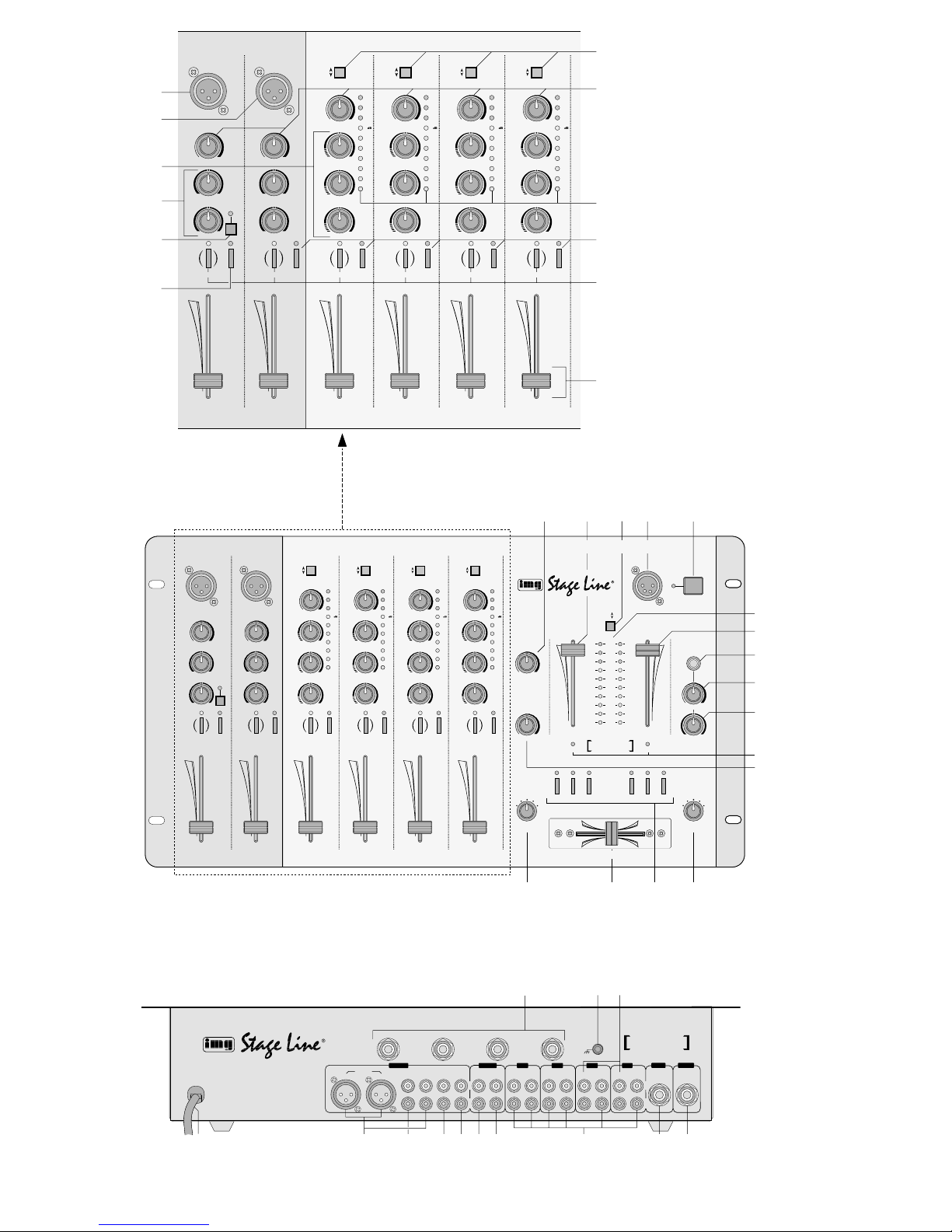
1.1 Frontplatte
1 XLR-Eingang (sym.) für den Anschluß eines DJ-
Mono-Mikrofons an den Kanal DJ MIC
[Bei Anschluß eines Mikrofons an die 6,3-mmKlinkenbuchse (41) des Kanals, wird diese Buchse abgeschaltet.]
2 XLR-Eingang (sym.) für den Anschluß eines Mo-
no-Mikrofons an den Kanal MIC 1
[Bei Anschluß eines Mikrofons an die 6,3-mmKlinkenbuchse (40) des Kanals, wird diese Buchse abgeschaltet.]
3 3fache Klangregelung (max. +15 dB,
-
30dB) für
die Kanäle 1–4: Höhenregler (HIGH), Mittenregler (MID) und Tiefenregler (LOW)
4 2fache Klangregelung (max. ±15 dB) für die Mi-
krofonkanäle: Höhenregler (HIGH) und Tiefenregler (LOW)
5 Taste AUTO TALK für die Talkover-Funktion:
Ist die Taste gedrückt, werden bei Durchsagen
über den DJ-Mikrofon-Kanal die Pegel der Kanäle 1–4 um 12dB abgesenkt.
6 Ein-/Ausschalter ON AIR für das DJ-Mikrofon
7 Umschalttasten für die Eingänge der Kanäle 1 –4
8 Gain-Regler zum Einstellen der Eingangsver-
stärkung für die Eingangskanäle
9 VU-Meter zur Anzeige des Pre Fader-Pegels
[Pegel vor dem Fader (12)] für die Kanäle 1–4
10 Tasten PFL zum Vorhören der Kanäle 1 – 4 und
des Mikrofonkanals MIC 1 über einen Kopfhörer
an der Buchse (20)
11 Tasten SEND zum Schalten der Eingangskanäle
auf den Pre Fader-Ausspielweg: bei gedrückter
T aste wird der jeweilige Kanal vor dem Fader (12)
auf den Ausgang SEND (38) gegeben
12 Pegelregler (Fader) für die Eingangskanäle
13 Pegelregler für den Monitorausgang BOOTH (35)
14 Pegelregler (Fader) für den Masterkanal A
15 Taste zum Umschalten des Stereo-VU-Meters
(18) zwischen den beiden Masterkanälen
Taste nicht gedrückt:
Pegel des Masterkanals Awird angezeigt
Taste gedrückt:
Pegel des Masterkanals B wird angezeigt
16 4polige XLR-Buchse LAMP zum Anschluß einer
Pultleuchte (12V/5W max.)
17 Ein-/Ausschalter des Mischpults
18 Stereo-VU-Meter; zeigt den Pegel des mit der
Umschalttaste (15) gewählten Masterkanals an
19 Pegelregler (Fader) für den Masterkanal B
20 6,3-mm-Klinkenbuchse zum Anschluß eines Ste-
reo-Kopfhörers (Impedanz ≥ 2 x 8Ω)
21 Pegelregler für den an der Buchse (20) ange-
schlossenen Kopfhörer
22 Regler MIX für den Kopfhörerausgang (20)
Position „PFL“:
Der Pre Fader-Pegel des Eingangskanals, dessen Taste PFL(10) gedrückt ist, wird abgehört.
Position „PROG.“:
Das laufende Musikprogramm wird vor den
Masterfadern (14 und 19) abgehört.
23 LEDs BEAT für die zwei Masterkanäle; leuchten
pulsierend im Rhythmus der Musik
24 Return-Regler zur Pegeleinstellung der vom Ef-
fektgerät zurückkommenden Signale
25 Zuordnungsschalter C.F. ASSIGN A für den
Crossfader (26); bestimmt, welcher der Kanäle
1– 4 eingeblendet wird, wenn der Crossfader
links steht
26 Überblendregler (Crossfader) zum Überblenden
zwischen zwei der Kanäle 1 – 4; die jeweiligen
Kanäle werden mit den beiden C.F. ASSIGNSchaltern (25 und 28) angewählt
27 CUT-Tasten zum Unterdrücken bestimmter Fre-
quenzbereiche für die zwei Kanäle, die für die
Überblendfunktion ausgewählt wurden:
Bei gedrückter Taste – HIGH für die Höhen, MID
für die Mitten, LOW für die Tiefen – wird das
jeweilige Frequenzband stark abgesenkt.
Please unfold page 3. Then you can always see
the operating elements and connections described.
Contents
1 Operating Elements and Connections . . 4
1.1 Front plate . . . . . . . . . . . . . . . . . . . . . . . . . . 4
1.2 Rear side . . . . . . . . . . . . . . . . . . . . . . . . . . . 5
2 Safety Notes . . . . . . . . . . . . . . . . . . . . . . . 5
3 Applications . . . . . . . . . . . . . . . . . . . . . . . . 5
4 Connection of the Mixer . . . . . . . . . . . . . . 5
4.1 Inputs . . . . . . . . . . . . . . . . . . . . . . . . . . . . . 5
4.2 Outputs . . . . . . . . . . . . . . . . . . . . . . . . . . . . 6
4.3 Connections for an effect unit . . . . . . . . . . . 6
4.4 Connections for the remote control of
CD players and turntables . . . . . . . . . . . . . . 6
4.5 Console illumination and mains voltage . . . 6
5 Operation . . . . . . . . . . . . . . . . . . . . . . . . . . 6
5.1 Basic settings . . . . . . . . . . . . . . . . . . . . . . . 6
5.1.1 Basic setting of the input channels . . . . . . 6
5.1.2 Settings when using an effect unit . . . . . . 7
5.2 Mixing of the audio sources . . . . . . . . . . . . 7
5.3 Crossfading between two channels/
cut function . . . . . . . . . . . . . . . . . . . . . . . . . 7
5.4 Talkover function for the DJ microphone . . . 7
5.5 Pre fader listening (PFL) via headphones . . 7
5.6 Monitoring of the music programme via a
monitor system . . . . . . . . . . . . . . . . . . . . . . 8
5.7 Remote-controlling of turntables and
CD players . . . . . . . . . . . . . . . . . . . . . . . . . 8
6 Specifications . . . . . . . . . . . . . . . . . . . . . . 8
1 Operating Elements and
Connections
1.1 Front plate
1 XLR input (bal.) for the connection of a DJ mono
microphone to the DJ MIC channel
[If a microphone is connected to the 6.3mm jack
(41) of the channel, this jack is switched off.]
2 XLR input (bal.) for the connection of a mono
microphone to the MIC 1 channel
[If a microphone is connected to the 6.3mm jack
(40) of the channel, this jack is switched off.]
3 3-way equalizer (max. +15 dB,
-
30 dB) for the
channels 1 to 4: HIGH, MID, and LOW controls
4 2-way equalizer (max. ±15dB) for the micro-
phone channels: HIGH and LOW controls
5 AUTO TALK button for the talkover function:
If the button is pressed, the levels of the channels 1 to 4 are attenuated by 12 dB in case of
announcements via the DJ microphone channel
6 On/off switch ON AIR for the DJ microphone
7 Selector buttons for the inputs of the channels 1
to 4
8 Gain controls for adjusting the input amplification
for the input channels
9 VU meters to display the pre fader level [level
ahead of the fader (12)] for channels 1 to 4
10 PFL buttons for pre fader listening of the chan-
nels 1 to 4 and the microphone channel MIC 1
via headphones connected to jack (20)
11 SEND buttons for switching the input channels to
the pre fader send way: with the button pressed,
the respective channel is fed to the SEND output
(38) ahead of the fader (12)
12 Level controls (faders) for the input channels
13 Level control for the monitor output BOOTH (35)
14 Level control (fader) for master channel A
15 Button to switch the stereo VU meter (18) be-
tween the two master channels
button not pressed:
the level of the master channel Ais displayed
button pressed:
the level of the master channel B is displayed
16 4-pole XLR jack LAMP for the connection of a
console lamp (12V/5W max.)
17 On/off switch of the mixer
18 Stereo VU meter; shows the level of the master
channel selected with the selector switch (15)
19 Level control (fader) for master channel B
20 6.3 mm jack for the connection of stereo head-
phones (impedance ≥ 2 x 8Ω)
21 Level control for the headphones connected to
the jack (20)
22 MIX control for the headphone output (20)
position “PFL”:
the pre fader level of the input channel of which
the PFL button (10) is pressed is monitored.
position “PROG.”:
the music programme currently playing is monitored ahead of the master faders (14 and 19).
23 BEAT LEDs for the two master channels; light in
a pulsating way to the rhythm of the music
24 Return control for the level adjustment of the sig-
nals coming from the effect unit
25 C.F. ASSIGN Aswitch for the crossfader (26); de-
fines which of the channels 1 to 4 is faded in if
the crossfader is in the left position
26 Crossfader for fading between two of the chan-
nels 1 to 4; the respective channels are selected
with the two C.F. ASSIGN switches (25 and 28)
27 CUT buttons for suppressing certain frequency
ranges for the two channels selected for the
crossfading function:
With the button pressed – HIGH for the high
range, MID for the midrange, LOW for the bass
range – the respective frequency band is
attenuated to a large extent.
28 C.F. ASSIGN B switch for the crossfader (26);
defines which of the channels 1 to 4 is faded in if
the crossfader is in the right position
4
GB
D
A
CH

28 Zuordnungsschalter C.F. ASSIGN B für den
Crossfader (26); bestimmt, welcher der Kanäle
1– 4 eingeblendet wird, wenn der Crossfader
rechts steht
1.2 Rückseite
29 6,3-mm-Klinkenbuchsen START zum Fernstar-
ten (Faderstart) von Platten- oder CD-Spielern
mit Kontaktsteuerung
30 Anschluß GND für einen gemeinsamen Masse-
punkt, z.B. für angeschlossene Plattenspieler
31 Stereo-Eingänge PHONO (Cinch) für die Kanäle
1 und 2 zum Anschluß von Plattenspielern mit
Magnetsystem
32 Netzkabel zum Anschluß des Gerätes an die
Stromversorgung (230V~/50Hz)
33 Stereo-Ausgänge des Masterkanals A – wahl-
weise XLR (sym.) oder Cinch – zum Anschluß
einer Endstufe
34 Stereo-Ausgang des Masterkanals B (Cinch)
zum Anschluß einer Endstufe
35 Stereo-Ausgang BOOTH (Cinch) zum Anschluß
einer Monitoranlage
36 Stereo-Ausgang REC (Cinch) für den Anschluß
eines Tonaufnahmegerätes; der Aufnahmepegel
ist unabhängig von der Stellung der Masterfader
(14 und 19)
37 Stereo-Eingang RETURN (Cinch) zum Anschluß
an den Ausgang eines Effektgerätes
38 Stereo-Ausgang SEND (Cinch) zum Anschluß
an den Eingang eines Effektgerätes
39 Stereo-Eingänge LINE und CD (Cinch) für die
Kanäle 1–4 zum Anschluß von Geräten mit
Line-Pegel-Ausgängen (z.B. MiniDisk-Recorder,
CD-Spieler, Tapedeck)
40 6,3-mm-Klinkenbuchse (sym.) für den Anschluß
eines Mono-Mikrofons an den Kanal MIC 1; bei
Anschluß eines Mikrofons an diese Buchse, wird
die XLR-Buchse (2) des Kanals abgeschaltet
41 6,3-mm-Klinkenbuchse (sym.) für den Anschluß
eines DJ-Mono-Mikrofons an den Kanal DJ MIC;
bei Anschluß eines Mikrofons an diese Buchse,
wird die XLR-Buchse (1) des Kanals abgeschaltet
2 Hinweise für den sicheren Gebrauch
Dieses Gerät entspricht der Richtlinie für elektromagnetische Verträglichkeit 89/ 336/EWG und der Niederspannungsrichtlinie 73/ 23/EWG.
Beachten Sie auch unbedingt die folgenden Punkte:
●
Verwenden Sie das Gerät nur im Innenbereich.
Schützen Sie es vor Tropf- und Spritzwasser, hoher Luftfeuchtigkeit und Hitze (zulässiger Einsatztemperaturbereich 0–40°C).
●
Stellen Sie keine mit Flüssigkeit gefüllten Gefäße,
z.B. Trinkgläser, auf das Gerät.
●
Nehmen Sie das Gerät nicht in Betrieb bzw. ziehen Sie sofort den Netzstecker, wenn:
1. sichtbare Schäden am Gerät oder an der Netzanschlußleitung vorhanden sind,
2. nach einem Sturz oder ähnlichem der Verdacht
auf einen Defekt besteht,
3. Funktionsstörungen auftreten.
Lassen Sie das Gerät in jedem Fall in einer Fachwerkstatt reparieren.
●
Eine beschädigte Netzanschlußleitung darf nur
durch den Hersteller oder durch eine autorisierte
Fachwerkstatt ersetzt werden.
●
Ziehen Sie den Netzstecker nie an der Zuleitung
aus der Steckdose.
●
Verwenden Sie für die Reinigung nur ein trockenes, weiches Tuch, auf keinen Fall Chemikalien
oder Wasser.
●
Wird das Gerät zweckentfremdet, nicht richtig angeschlossen, falsch bedient oder nicht fachge-
recht repariert, kann für eventuelle Schäden keine
Haftung übernommen werden.
●
Soll das Gerät endgültig aus dem Betrieb genommen werden, übergeben Sie es zur umweltgerechten Entsorgung einem örtlichen Recyclingbetrieb.
3 Einsatzmöglichkeiten
Das Mischpult MPX-206 mit vier Stereo-Eingangskanälen, einem Mikrofonkanal MIC 1 und einem DJMikrofonkanal ist für beliebige DJ-Anwendungen im
privaten oder professionellen Bereich geeignet.
Das Gerät kann sowohl frei aufgestellt als auch in
ein Bedienpult eingebaut werden. Es eignet sich
ebenso für die Montage in ein Rack (482mm / 19").
Für die Rackmontage wird eine Höhe von 6HE
(1 Höheneinheit = 44,45 mm) benötigt.
4 Mischpult anschließen
Vor dem Anschließen von Geräten bzw. Ändern bestehender Anschlüsse das Mischpult ausschalten.
4.1 Eingänge
1) Die T onquellen an die entsprechenden Eingangs-
buchsen der Eingangskanäle anschließen [Mono-
Eingänge für die zwei Mikrofonkanäle, Stereo-
Eingänge für die Kanäle 1–4 (weiße Buchse
LEFT = linker Kanal, rote Buchse RIGHT = rech-
ter Kanal)]:
– ein DJ-Mikrofon an die Eingangsbuchse (1
oder 41) des Kanals DJ MIC;
– ein weiteres Mikrofon an die Eingangsbuchse
(2 oder 40) des Kanals MIC 1;
– Geräte mit Line-Pegel-Ausgang (z.B. CD-
Spieler, MiniDisk-Recorder, Tapedeck) an die
Buchsen CD oder LINE (39);
– Plattenspieler mit Magnetsystem an die Buch-
sen PHONO (31). Die Klemmschraube GND
(30) kann als gemeinsamer Massepunkt ge-
Achtung! Das Gerät wird mit lebensgefährlicher
Netzspannung (230 V~) versorgt. Nehmen Sie deshalb niemals selbst Eingriffe im Gerät vor. Durch unsachgemäßes Vorgehen besteht die Gefahr
eines elektrischen Schlages. Außerdem
erlischt beim Öffnen des Gerätes jeglicher Garantieanspruch.
1.2 Rear side
29 6.3 mm jacks START for remote starting (fader
start) of turntables or CD players with contact
control
30 GND connection for a common grounding point,
e.g. for connected turntables
31 Stereo inputs PHONO (phono jacks) for the
channels 1 and 2 to connect turntables with
magnetic system
32 Mains cable for the connection of the unit to the
power supply (230V~/50Hz)
33 Stereo outputs of master channel A – either XLR
jacks (bal.) or phono – to connect a power amplifier
34 Stereo output of the master channel B (phono
jacks) to connect a power amplifier
35 Stereo output BOOTH (phono jacks) to connect
a monitor system
36 Stereo output REC (phono jacks) to connect an
audio recording unit; the recording level is independent of the position of the master faders (14
and 19)
37 Stereo input RETURN (phono jacks) for the con-
nection to the output of an effect unit
38 Stereo output SEND (phono jacks) for the con-
nection to the input of an effect unit
39 Stereo inputs LINE and CD (phono) for the chan-
nels 1 to 4 to connect units with line level outputs
(e.g. minidisk recorder, CD player, tape deck)
40 6.3 mm jack (bal.) for the connection of a mono
microphone to the MIC 1 channel; with connection of a microphone to this jack, the XLR jack (2)
of the channel is switched off
41 6.3 mm jack (bal.) for the connection of a DJ
mono microphone to the DJ MIC channel; if a
microphone is connected to this jack, the XLR
jack (1) of the channel is switched off
2 Safety Notes
This unit corresponds to the directive for electromagnetic compatibility 89/ 336 /EEC and to the low
voltage directive 73/23/EEC.
Please observe the following items in any case:
●
The unit is suitable for indoor use only. Protect it
against dripping water and splash water, high
humidity, and heat (admissible ambient temperature range 0–40°C).
●
Do not place any vessels filled with liquid, e. g.
drinking glasses, on the unit.
●
Do not operate the unit or immediately disconnect
the plug from the mains socket
1. if there is visible damage to the unit or to the
mains cable.
2. if a defect might have occurred after the unit
was dropped or suffered a similar accident.
3. if malfunctions occur.
In any case the unit must be repaired by authorized personnel.
●
A damaged mains cable may only be repaired by
the manufacturer or by authorized skilled personnel.
●
Never pull the mains cable to disconnect the
mains plug from the socket.
●
For cleaning only use a dry soft cloth, by no
means chemicals or water.
●
If the unit is used for other purposes than originally
intended, if it is not connected or operated in the
correct way or not repaired by authorized personnel, no liability for any damage will be accepted.
●
If the unit is to be put out of operation permanently,
take it to a local recycling plant for a disposal
which is not harmful to the environment.
●
Important for U.K. Customers!
The wires in this mains lead are coloured in
accordance with the following code:
blue = neutral
brown = live
As the colours of the wires in the mains lead of this
appliance may not correspond with the coloured
markings identifying the terminals in your plug,
proceed as follows:
1. The wire which is coloured blue must be
connected to the terminal in the plug which is
marked with the letter N or coloured black.
2. The wire which is coloured brown must be
connected to the terminal which is marked with
the letter L or coloured red.
3 Applications
The mixer MPX-206 with four stereo input channels,
a microphone channel MIC 1 and a DJ microphone
channel is suitable for any private or professional DJ
applications.
The unit can be used as a table top unit as well as
be installed into a console. It is suitable for mounting
into a rack (482mm/19") as well. For the rack
mounting a height of 6 rack spaces (1 rack space =
44.45mm) is necessary.
4 Connection of the Mixer
Prior to connecting units or changing existing
connections switch off the mixer.
4.1 Inputs
1) Connect the audio sources to the corresponding
input jacks of the input channels [mono inputs for
the two microphone channels, stereo inputs for
the channels 1 to 4 (white jack = left channel, red
jack = right channel)]:
– a DJ microphone to the input jack (1 or 41) of
the DJ MIC channel;
Attention! The unit is supplied with hazardous
mains voltage (230V~). Leave servicing
to authorized personnel only. Inexpert
handling may cause an electric shock
hazard. Furthermore, any guarantee
claim will expire if the unit has been
opened.
5
GB
D
A
CH
 Loading...