

IMG STAGE LINE MPX-202 Instruction Manual
BEDIENUNGSANLEITUNG • INSTRUCTION MANUAL • MODE D’EMPLOI
ISTRUZIONI PER L’USO • GEBRUIKSAANWIJZING • MANUAL DE INSTRUCCIONES • INSTRUKCJA OBSŁUGI
SIKKERHEDSOPLYSNINGER • SÄKERHETSFÖRESKRIFTER • TURVALLISUUDESTA
2-KANAL-STEREO-MISCHPULT
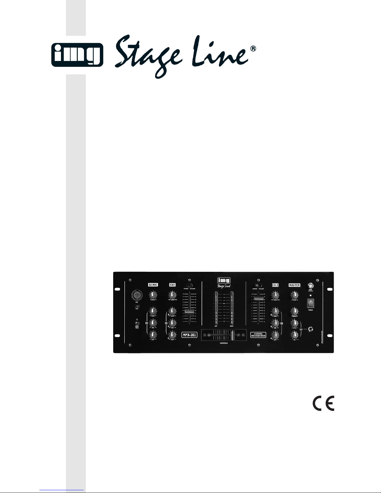
2-CHANNEL STEREO MIXER
TABLE DE MIXAGE STÉRÉO 2 CANAUX
MIXER STEREO A 2 CANALI
MPX-202 Best.-Nr. 20.2370

2
wwwwww..iimmggssttaaggeelliinnee..ccoomm
Bevor Sie einschalten …
Wir wünschen Ihnen viel Spaß mit Ihrem neuen Gerät
von „img Stage Line”. Bitte lesen Sie diese Bedienungsanleitung vor dem Betrieb gründlich durch. Nur so lernen
Sie alle Funktionsmöglichkeiten kennen, vermeiden
Fehlbedienungen und schützen sich und Ihr Gerät vor
eventuellen Schäden durch unsachgemäßen Gebrauch.
Heben Sie die Anleitung für ein späteres Nachlesen auf.
Der deutsche Text beginnt auf der Seite 4.
Before you switch on …
We wish you much pleasure with your new “img Stage
Line” unit. Please read these operating instructions
carefully prior to operating the unit. Thus, you will get to
know all functions of the unit, operating errors will be
prevented, and yourself and the unit will be protected
against any damage caused by improper use. Please
keep the operating instructions for later use.
The English text starts on page 4.
D
A
CH
GB
Avant toute installation …
Nous vous souhaitons beaucoup de plaisir à utiliser cet
appareil “img Stage Line”. Lisez ce mode d’emploi entièrement avant toute utilisation. Uniquement ainsi, vous pourrez apprendre l’ensemble des possibilités de fonctionnement de l’appareil, éviter toute manipulation erronée et
vous protéger, ainsi que l’appareil, de dommages éventuels engendrés par une utilisation inadaptée. Conservez
la notice pour pouvoir vous y reporter ultérieurement.
La version française se trouve page 8.
Prima di accendere …
Vi auguriamo buon divertimento con il vostro nuovo apparecchio di “img Stage Line”. Leggete attentamente le
istruzioni prima di mettere in funzione l’apparecchio.
Solo così potete conoscere tutte le funzionalità, evitare
comandi sbagliati e proteggere voi stessi e l’apparecchio
da eventuali danni in seguito ad un uso improprio. Conservate le istruzioni per poterle consultare anche in
futuro.
Il testo italiano inizia a pagina 8.
F
B
CH
I
Voor u inschakelt …
Wij wensen u veel plezier met uw nieuwe apparaat van
“img Stage Line”. Lees deze gebruikershandleiding
grondig door, alvorens het apparaat in gebruik te nemen.
Alleen zo leert u alle functies kennen, vermijdt u foutieve
bediening en behoedt u zichzelf en het apparaat voor
eventuele schade door ondeskundig gebruik. Bewaar de
handleiding voor latere raadpleging.
De Nederlandstalige tekst vindt u op pagina 12.
Antes de la utilización …
Le deseamos una buena utilización para su nuevo aparato “img Stage Line”. Por favor, lea estas instrucciones
de uso atentamente antes de hacer funcionar el aparato.
De esta manera conocerá todas las funciones de la
unidad, se prevendrán errores de operación, usted y el
aparato estarán protegidos en contra de todo daño causado por un uso inadecuado. Por favor, guarde las
instrucciones para una futura utilización.
El texto en español empieza en la página 12.
NL
B
E
Før du tænder …
God fornøjelse med dit nye “img Stage Line” produkt.
Læs venligst sikkerhedsanvisningen nøje, før du tager
produktet i brug. Dette hjælper dig med at beskytte produktet mod ukorrekt ibrugtagning. Gem venligst denne
betjeningsvejledning til senere brug.
Du finder sikkerhedsanvisningen på side 20.
Ennen kytkemistä …
Toivomme Sinulle paljon miellyttäviä hetkiä uuden “img
Stage Line” laitteen kanssa. Ennen laitteen käyttöä
Sinua huolellisesti tutustumaan turvallisuusohjeisiin.
Näin vältyt vahingoilta, joita virheellinen laitteen käyttö
saattaa aiheuttaa. Ole hyvä ja säilytä käyttöohjeet myöhempää tarvetta varten.
Turvallisuusohjeet löytyvät sivulta 20.
DK
FIN
Innan du slår på enheten …
Vi önskar dig mycket glädje med din nya “img Stage
Line” produkt. Läs igenom säkerhetsföreskrifterna noga
innan enheten tas i bruk. Detta kan förhindra att problem
eller fara för dig eller enheten uppstår vid användning.
Spara instruktionerna för framtida användning.
Säkerhetsföreskrifterna återfinns på sidan 20.
S
Przed uruchomieniem …
Życzymy zadowolenia z nowego produktu “img Stage
Line”. Dzięki tej instrukcji obsługi będą państwo w stanie
poznać wszystkie funkcje tego urządzenia. Stosując się
do instrukcji unikną państwo błędów i ewentualnego
uszkodzenia urządzenia na skutek nieprawidłowego
użytkowania. Prosimy zachować instrukcję.
Tekst polski zaczyna się na stronie 16.
PL
GND
CD/LINEPHONO PHONO CD/ LINE
MASTER
REC
R
L
CH2 CH1 DJMICOUTPUT
R
L
Remove the mains plug before opening the unit. Leave replacing of the mains supply cord and mains fuse to qualified
service personnel. Protect the unit against moisture and heat. Permissible operating temperature range 0
-
40°C. This
product is not intended for use other than stated.
Vor Öffnen des Gerätes Netzstecker ziehen, Netzleitung und Netzsicherung nur von Fachpersonal wechseln lassen. Gerät
vor Feuchtigkeit und Hitze schützen. Zulässiger Einsatztemperaturbereich 0
-
40°C. Gerät nur für den angegebenen Zweck
verwenden.
Avant d'ouvrir l'appareil, retirez la fiche secteur d'alimentation. Toute intervention sur le câble secteur et le fusible secteur
doit être effectuée uniquement par du personnel qualifié. Protegez l'appareil de l'humidité et de la chaleur. Plage autorisée
de la température d'utilisation 0
-
40°C. À n'utiliser que dans le domaine d'application déterminé.
Staccare la spina di rete prima di aprire l'apparecchio, e far cambiare il cavo di rete ed il fusibile di rete solo da persona
esperta. Proteggere l'apparecchio dall'umidità e dal calore. Campo della temperatura d'impiego ammessa 0
-
40°C. Usare
l'apparecchio solo per lo scopo indicato.
CAUTION! ATTENTION!ACHTUNG! ATTENZIONE!
230V~/50Hz
12VA
MAINS
S/N
tf115°C
MONACOR® INTERNATIONAL
BOOTH
1 – GND
2 – HOT
3 – COLD
LEFTRIGHT
BALANCED
MPX-202
2-CHANNEL
PRO SOUND MIXER
WWW.IMGSTAGELINE.COM
3
12 3 4 5 6 7 89 10 111213
➁
➀
LEVEL
MIN MAX
LOW
–
15 +15
MID
+15
HIGH
+15
EQ
10
9
8
7
6
5
4
3
2
1
0
10
9
8
7
6
5
4
3
2
1
0
PHONO CD/ LINE
LAMP
12V/5W
RIGHTLEFT
POWER
10
9
8
7
6
5
4
3
2
1
0
10
9
8
7
6
5
4
3
2
1
0
PHONO CD/ LINE
AUTO
TALK
LEVEL
010
MIX
CH1 CH2
BOOTH
LEVEL
CROSSFADER
-20
-15
-10
-7
-5
-3
0dB
+3
+6
+9
LOW
+15
MID
+15
HIGH
+15
–
30
GAIN
010
EQ
LOW
+15
MID
+15
HIGH
+15
EQ
GAIN
MPX-202
2-CHANNEL
PRO SOUND MIXER
MIC
PAD
WWW.IMGSTAGELINE.COM
MIN MAX
010
010
CUT
–
30
–
30
–
15
–
15
–
30
–
30
–
30
CUT
CUT
CUT
CUT
CUT
14 15 16 17 18 19 20 21 22 23
24 25 26 27 28 29 30 31 32

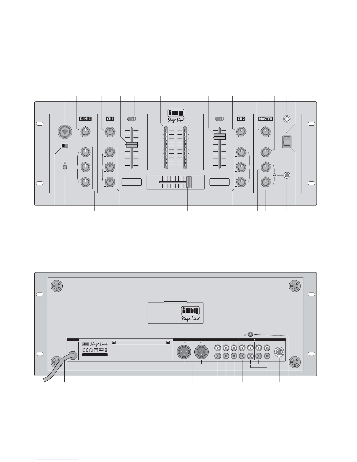
Bitte klappen Sie die Seite 3 heraus. Sie sehen
dann immer die beschriebenen Bedienelemente
und Anschlüsse.
1 Übersicht der Bedienelemente und
Anschlüsse
1.1 Frontseite
1 Mikrofoneingang (XLR/6,3-mm-Klinken-Kombi-
buchse, sym.) für den Anschluss eines DJ-Mikrofons, alternativ zur der Buchse (31) auf der
Rückseite
2 Pegelregler für den Mikrofonkanal
3 GAIN-Regler für die Eingangsverstärkung des
Kanals CH1
4 Pegelregler (Fader) für den Kanal CH1
5 Eingangswahlschalter PHONO– CD/LINE für
den Kanal CH1
6 Stereo-VU-Meter; zeigt den Pegel an den Aus-
gängen RIGHT , LEFT(25) und MASTER (26) an
7 Pegelregler (Fader) für den Kanal CH2
8 Eingangswahlschalter PHONO– CD/LINE für
den Kanal CH2
9 GAIN-Regler für die Eingangsverstärkung des
Kanals CH2
10 Pegelregler für das Summensignal (Master)
[Buchsen RIGHT, LEFT (25) und MASTER (26)]
11 Pegelregler für den Ausgang BOOTH (27)
12 BNC-Buchse LAMP zum Anschluss einer
Schwanenhalsleuchte (12V/5W max.),
z.B. GNL-204 oder GNL-205 von „img Stage Line“
13 Betriebsanzeige
14 PAD-Schalter für den Mikrofonkanal: in der rech-
ten Position wird das Mikrofonsignal um 20 dB
verringert
15 Taste AUTO TALK für Mikrofondurchsagen:
Ist die Taste gedrückt, werden bei Durchsagen
über das DJ-Mikrofon die Pegel der Kanäle
CH1 und CH2 um 12dB abgesenkt.
16 Klangregelung für das Mikrofon:
HIGH für die Höhen (±15dB/10 kHz)
MID für die Mitten (±15dB/1 kHz)
LOW für die Bässe (±15dB/50 Hz)
17 Klangregelung für den Kanal CH1:
HIGH für die Höhen (+15dB,
-
30dB/10kHz)
MID für die Mitten (+15dB, -30dB/1kHz)
LOW für die Bässe (+15dB, -30dB/50Hz)
18 Überblendregler CROSSFADER zum Überblen-
den zwischen den Kanälen CH1 und CH 2
19 Klangregelung für den Kanal CH 2, Regelberei-
che siehe Kanal CH1, Position 17
20 Lautstärkeregler für einen an der Buchse (22)
angeschlossenen Kopfhörer
21 Regler MIX für den Kopfhörerausgang (22):
Position „CH1“ (Regler ganz links):
Das Pre-Fader-Signal des Kanals CH 1 wird
über den Kopfhörer abgehört.
Position „CH2“ (Regler ganz rechts):
Das Pre-Fader-Signal des Kanals CH 2 wird
über den Kopfhörer abgehört.
22 6,3-mm-Klinkenbuchse zum Anschluss eines
Stereo-Kopfhörers (Impedanz min. 8Ω)
23 Ein-/Ausschalter
1.2 Rückseite
24 Netzkabel zum Anschluss an eine Steckdose
(230V~/50Hz)
25 Ausgang (XLR, sym.) für das Summensignal
zum Anschluss eines Verstärkers
26 Ausgang (Cinch) für das Summensignal zum An-
schluss eines Verstärkers
27 Monitorausgang BOOTH (Cinch) zum Anschluss
einer Monitoranlage
28 Aufnahmeausgang REC (Cinch) zum Anschluss
an den Eingang eines Tonaufnahmegerätes; der
Aufnahmepegel ist unabhängig vom Regler
MASTER LEVEL (10)
29 Eingänge PHONO (Cinch) der Kanäle CH1 und
CH2 zum Anschluss von Plattenspielern mit
Magnetsystem
30 Eingänge CD/LINE (Cinch) der Kanäle CH 1 und
CH2 zum Anschluss von Geräten mit LinePegel-Ausgängen (z.B. CD-Spieler, MiniDiscRecorder, Kassettenrecorder)
31 Mikrofoneingang (6,3-mm-Klinke, sym.), alterna-
tiv zum Anschluss (1) auf der Frontseite
32 Klemmschraube GND für den gemeinsamen
Masseanschluss von Plattenspielern
Please take out page 3. Then you can always see
the operating elements and connections described.
1 Operating Elements and Connec-
tions
1.1 Front panel
1 Microphone input (combined XLR/ 6.3 mm jack,
bal.) for connecting a DJ microphone, as an
alternative to the jack (31) on the rear panel
2 Level control for the microphone channel
3 GAIN control for the input amplification of chan-
nel CH1
4 Level control (fader) for channel CH 1
5 Input selector switch PHONO– CD/LINE for
channel CH1
6 Stereo VU-meter, to indicate the level at the out-
puts RIGHT, LEFT (25), and MASTER (26)
7 Level control (fader) for channel CH2
8 Input selector switch PHONO– CD/LINE for
channel CH2
9 GAIN control for the input amplification of chan-
nel CH2
10 Level control for the master signal
[jacks RIGHT, LEFT (25), and MASTER (26)]
11 Level control for the output BOOTH (27)
12 BNC jack LAMP for connecting a gooseneck
light (12V/5 W max.), e.g. GNL-204 or GNL-205
from “img Stage Line”
13 Power LED
14 PAD switch for the microphone channel: with the
switch set to the right, the microphone signal will
be attenuated by 20dB
15 Button AUTO TALK for microphone announce-
ments:
With the button pressed, the levels of the
channels CH 1 and CH 2 will be attenuated by
12 dB when announcements are made via the
DJ microphone.
16 Equalizer for the microphone:
HIGH (±15dB/10 kHz)
MID (±15dB/1kHz)
LOW (±15dB/50Hz)
17 Equalizer for channel CH1:
HIGH (+15 dB,
-
30dB/10kHz)
MID (+15dB, -30dB/1kHz)
LOW (+15 dB, -30dB/50Hz)
18 Crossfader for crossfading between the chan-
nels CH1 and CH 2
19 Equalizer for channel CH 2, control ranges see
channel CH1, item 17
20 Volume control for headphones connected to the
jack (22)
21 Control MIX for the headphone output (22):
position “CH1” (control at the left stop):
The prefader signal of channel CH1 is monitored via headphones.
position “CH2” (control at the right stop):
The prefader signal of channel CH2 is monitored via headphones.
22 6.3 mm jack for connecting stereo headphones
(minimum impedance 8Ω)
23 POWER switch
1.2 Rear panel
24 Mains cable for connection to a mains socket
(230V~/50Hz)
25 Output (XLR, bal.) for the master signal for
connection of an amplifier
26 Output (phono jacks) for the master signal for
connection of an amplifier
27 Monitor output BOOTH (phono jacks) for con-
nection of a monitoring system
28 Recording output REC (phono jacks) for connec-
tion to the input of an audio recorder; the recording level is independent of the control MASTER
LEVEL (10)
29 Inputs PHONO (phono jacks) of the channels
CH1 and CH 2 for connection of turntables with
magnetic system
30 Inputs CD/ LINE (phono jacks) of the channels
CH 1 and CH 2 for connection of units with line
level outputs (e.g. CD player, minidisk recorder,
cassette recorder)
31 Microphone input (6.3mm jack, bal.), as an alter-
native to the connection (1) on the front panel
32 Clamping screw GND for the common ground
connection of turntables
4
GB
D
A
CH
2 Hinweise für den sicheren Gebrauch
Das Gerät entspricht allen erforderlichen Richtlinien
der EU und ist deshalb mit gekennzeichnet.
Beachten Sie auch unbedingt die folgenden Punkte:
●
Das Gerät ist nur zur Verwendung im Innenbereich geeignet. Schützen Sie es vor Tropf- und
Spritzwasser, hoher Luftfeuchtigkeit und Hitze
(zulässiger Einsatztemperaturbereich 0– 40°C).
●
Stellen Sie keine mit Flüssigkeit gefüllten Gefäße,
z.B. Trinkgläser, auf das Gerät.
●
Nehmen Sie das Gerät nicht in Betrieb und ziehen
Sie sofort den Netzstecker aus der Steckdose,
wenn:
1. sichtbare Schäden am Gerät oder an der Netzanschlussleitung vorhanden sind,
2. nach einem Sturz oder Ähnlichem der Verdacht
auf einen Defekt besteht,
3. Funktionsstörungen auftreten.
Lassen Sie das Gerät in jedem Fall in einer Fachwerkstatt reparieren.
●
Eine beschädigte Netzanschlussleitung darf nur
durch eine Fachwerkstatt ersetzt werden.
●
Ziehen Sie den Netzstecker nie an der Zuleitung
aus der Steckdose, fassen Sie immer am Stecker
an.
●
Verwenden Sie zum Reinigen nur ein trockenes,
weiches Tuch, niemals Wasser oder Chemikalien.
●
Wird das Gerät zweckentfremdet, nicht richtig
angeschlossen, falsch bedient oder nicht fachgerecht repariert, kann keine Garantie für das Gerät
und keine Haftung für daraus resultierende Sachoder Personenschäden übernommen werden.
WARNUNG Das Gerät wird mit lebensgefähr-
licher Netzspannung (230V~) versorgt. Nehmen Sie deshalb nie selbst
Eingriffe am Gerät vor. Durch unsachgemäßes Vorgehen besteht die
Gefahr eines elektrischen Schlages.
2 Safety Notes
This unit corresponds to all required directives of the
EU and is therefore marked with .
Please observe the following items in any case:
●
The unit is suitable for indoor use only. Protect it
against dripping water and splash water, high air
humidity, and heat (admissible ambient temperature range 0– 40°C).
●
Do not place any vessel filled with liquid on the
unit, e.g. a drinking glass.
●
Do not operate the unit or immediately disconnect
the plug from the mains socket
1. if there is visible damage to the unit or to the
mains cable,
2. if a defect might have occurred after the unit
was dropped or suffered a similar accident,
3. if malfunctions occur.
In any case the unit must be repaired by skilled
personnel.
●
A damaged mains cable must be replaced by
skilled personnel only.
●
Never pull the mains cable for disconnecting the
mains plug from the socket, always seize the plug.
●
For cleaning only use a dry, soft cloth; never use
chemicals or water.
●
No guarantee claims for the unit and no liability for
any resulting personal damage or material
damage will be accepted if the unit is used for
other purposes than originally intended, if it is not
correctly connected, operated, or not repaired in
an expert way.
●
Important for U.K. Customers!
The wires in this mains lead are coloured in
accordance with the following code:
blue = neutral
brown = live
As the colours of the wires in the mains lead of this
appliance may not correspond with the coloured
markings identifying the terminals in your plug,
proceed as follows:
1. The wire which is coloured blue must be connected to the terminal in the plug which is
marked with the letter N or coloured black.
2. The wire which is coloured brown must be connected to the terminal which is marked with the
letter L or coloured red.
3 Applications
The mixer MPX-202 with two stereo input channels
and one DJ microphone channel is suitable for
various private or professional DJ applications.
The mixer can be installed either into a console
or into a rack (482mm/ 19"). For rack installation, a
height of 4RS (rack spaces) = 178 mm is required.
4 Connecting the Mixer
Prior to connecting any units or to changing any
existing connections, switch off the mixer and all
other audio units or set all output signals to zero.
4.1 Inputs
1) Connect the stereo audio sources to the corre-
sponding phono input jacks of the channels CH1
and CH 2 (jack L = left channel; jack R = right
channel):
– units with line level output (e. g. minidisk re-
corder, CD player, cassette recorder) to the
jacks CD/LINE (30);
– turntables with magnetic system to the jacks
PHONO (29). The clamping screw GND (32)
can be used as a common ground: Connect
the ground connection of the turntables to the
clamping screw.
2) Amicrophone with 6.3 mm plug or XLR plug can be
connected to the jack MIC (1) on the front panel.
Alternatively, the jack DJ MIC (31) on the rear panel
can be used, however, only with a 6.3mm plug.
4.2 Outputs
1) Connect the amplifiers or other subsequent units
with line input level (e. g. second mixer) to the
corresponding output jacks:
– The master signal is available at the XLR out-
puts RIGHT and LEFT (25) and at the phono
outputs MASTER (26). The XLR outputs
should be preferred. The balanced signal
transmission offers a higher protection against
interference which particularly may occur with
long connection cables.
– The output BOOTH (27) allows e. g. connec-
tion of an amplifier for a monitoring system.
2) For audio recordings, connect a recorder to the
output REC (28). The recording signal is independent of the position of the control MASTER
LEVEL (10).
3) Via stereo headphones, it is possible to monitor
the signals of the input channels CH1 and CH 2
ahead of the channel faders (4, 7) [see chapter
5.4]. Connect the headphones (minimum impedance 8Ω) to the jack (22).
4.3 Mixer illumination and mains connection
For an optimum mixer illumination, connect a gooseneck light (12V/5 W max.), e.g. the light GNL-204 or
GNL-205 from “img Stage Line”, to the BNC jack
LAMP (12). The light is switched on and off with the
mixer.
Finally connect the plug of the mains cable (24)
to a mains socket (230V~/50Hz).
If the unit is to be put out of operation definitively, take it to a local recycling plant for
a disposal which is not harmful to the environment.
WARNING The unit is supplied with hazardous
mains voltage (230V~). Leave servicing to skilled personnel only. Inexpert
handling may cause an electric shock
hazard.
5
GB
D
A
CH
3 Einsatzmöglichkeiten
Das Mischpult MPX-202 mit zwei Stereo-Eingangskanälen und einem DJ-Mikrofonkanal ist für vielfältige DJ-Anwendungen im privaten und professionellen Bereich geeignet.
Das Gerät kann sowohl in ein Bedienpult eingebaut als auch in ein Rack (482mm /19") eingesetzt
werden. Für die Rackmontage wird eine Höhe von
4HE (Höheneinheiten) = 178 mm benötigt.
4 Mischpult anschließen
Vor dem Anschließen von Geräten oder vor dem
Ändern bestehender Anschlüsse das Mischpult und
alle anderen Audiogeräte ausschalten oder alle Ausgangssignale auf Null stellen.
4.1 Eingänge
1) Die Stereo-Tonquellen an die entsprechenden
Cinch-Eingangsbuchsen der Kanäle CH1 und
CH2 anschließen (Buchse L = linker Kanal;
Buchse R = rechter Kanal):
– Geräte mit Line-Pegel-Ausgang (z.B. MiniDisc-
Recorder, CD-Spieler, Kassettenrecorder) an
die Buchsen CD/LINE (30);
– Plattenspieler mit Magnetsystem an die Buch-
sen PHONO (29). Die Klemmschraube GND
(32) kann als gemeinsamer Massepunkt genutzt werden: Den Masseanschluss der Plattenspieler mit der Klemmschraube verbinden.
2) Ein Mikrofon mit 6,3-mm-Klinken- oder XLR-
Stecker lässt sich an die Buchse MIC (1) auf der
Frontseite anschließen. Alternativ kann auch auf
der Rückseite die Buchse DJ MIC (31) verwendet
werden, jedoch nur mit einem 6,3-mm-Klinkenstecker.
4.2 Ausgänge
1) Die Verstärker oder andere nachfolgende Geräte
mit Line-Eingangspegel (z.B. zweites Mischpult)
an die entsprechenden Ausgangsbuchsen anschließen:
– Das Summensignal (Master) steht an den
XLR-Ausgängen RIGHTund LEFT(25) und an
den Cinch-Ausgängen MASTER (26) zur Verfügung. Die XLR-Ausgänge sollten bevorzugt
verwendet werden. Die symmetrische Signalübertragung bietet einen besseren Schutz
gegen Störeinstrahlungen, die besonders bei
längeren Anschlusskabeln auftreten können.
– An den Ausgang BOOTH (27) kann z.B. ein
Verstärker für eine Monitoranlage angeschlossen werden.
2) Für Tonaufnahmen ein Aufnahmegerät an den
Ausgang REC (28) anschließen. Das Aufnahmesignal ist unabhängig von der Stellung des Reglers MASTER LEVEL (10).
3) Über einen Stereo-Kopfhörer können die Signale
der Eingangskanäle CH1 und CH 2 vor den
Kanalfadern (4, 7) abgehört werden (siehe Kapitel 5.4). Den Kopfhörer (Impedanz min. 8 Ω) an
die Buchse (22) anschließen.
4.3 Pultbeleuchtung und Netzanschluss
Für eine optimale Pultbeleuchtung kann an die
BNC-Buchse LAMP (12) eine Schwanenhalsleuchte
(12 V/5 W max.) angeschlossen werden, z.B. die
Leuchte GNL-204 oder GNL-205 von „img Stage
Line“. Die Leuchte wird mit dem Mischpult ein- und
ausgeschaltet.
Zuletzt den Stecker des Netzkabel (24) in eine
Steckdose (230V~/50Hz) stecken.
Soll das Gerät endgültig aus dem Betrieb
genommen werden, übergeben Sie es zur
umweltgerechten Entsorgung einem örtlichen Recyclingbetrieb.

5 Bedienung
Vor dem Einschalten sollten die Regler MASTER
LEVEL (10) und BOOTH (11) auf Null gestellt werden, um Einschaltgeräusche zu vermeiden. Dann
das Mischpult mit dem Schalter POWER (23) einschalten. Die Betriebsanzeige (13) leuchtet. Anschließend die angeschlossenen Geräte einschalten.
Die folgenden Bedienschritte dienen nur als Hilfestellung, es sind auch andere Vorgehensweisen möglich.
5.1 Grundeinstellung der Stereo-Eingangskanäle CH 1 und CH 2
1) Zunächst die zwei GAIN-Regler (3, 9) und alle
neun Klangregler (16, 17, 19) in die Mittelposition
drehen.
2) Den Regler LEVEL (2) für den Mikrofonkanal vor-
erst auf „0“ drehen.
3) Die an den Kanälen CH 1 und CH2 angeschlos-
senen Geräte mit den Eingangswahlschaltern
PHONO – CD /LINE (5, 8) anwählen. Sind zwei
Geräte an einem Kanal angeschlossen, das gewünschte Gerät auswählen.
4) Jeweils ein Tonsignal (Testsignal oder Musik-
stück) auf die Eingangskanäle geben und die
Kanalfader (4, 7) auf ca.
2
/3 des Maximums auf-
ziehen, z.B. auf die Position 7.
5) Den Summenregler MASTER LEVEL (10) auf ca.
2
/3 des Maximums stellen.
6) Den Crossfader (18) ganz nach links schieben
und anhand des Stereo-VU-Meters (6) den Kanal
CH1 mit dem GAIN-Regler (3) optimal aussteuern. Bei durchschnittlich lauten Passagen
sollten Werte im 0-dB-Bereich angezeigt werden.
Falls erforderlich, kann der GAIN-Regler ganz
zu- oder aufgedreht werden.
7) Den Klang mit den Reglern (17) einstellen. Die
Höhen (Regler HIGH), Mitten (Regler MID) und
Tiefen (Regler LOW) lassen sich bis zu 15 dB
anheben oder bis zu 30dB stark absenken (CutFunktion). Eventuell nach der Klangeinstellung
den Kanalpegel mit dem GAIN-Regler (3) oder
Kanalfader (4) korrigieren.
8) Den Crossfader ganz nach rechts schieben und
den Kanal CH2 mit dem GAIN-Regler (9) aussteuern. Den Klang mit den Reglern (19) einstellen.
5.2 Überblenden zwischen den Kanälen CH1
und CH2 oder Mischen der Kanäle
1) Mit dem Crossfader (18) zwischen den Kanälen
CH1 und CH 2 überblenden.
Den Crossfader nach links schieben:
Der Kanal CH1 wird eingeblendet und der Kanal
CH2 ausgeblendet.
Den Crossfader nach rechts schieben:
Der Kanal CH2 wird eingeblendet und der Kanal
CH1 ausgeblendet.
2) Zum Mischen der beiden Kanäle den Crossfader
in die Mittelposition stellen. Die Kanäle sind dann
gleich laut zu hören.
Soll ein Kanal leiser als der andere zu hören
sein, den Crossfader entsprechend weiter nach
links oder rechts schieben.
3) Mit dem Regler MASTER LEVEL (10) die gewünschte Lautstärke für die Ausgänge RIGHT,
LEFT (25) und MASTER (26) einstellen. Der
Pegel wird von dem Stereo-VU-Meter (6) angezeigt. In der Regel wird eine optimale Aussteuerung erreicht, wenn das VU-Meter bei
durchschnittlich lauten Passagen Werte im 0-dBBereich anzeigt. Ist der Ausgangspegel jedoch
für das nachfolgende Gerät zu hoch oder zu
niedrig, den Signalpegel entsprechend verringern oder erhöhen.
4) Mit dem Regler BOOTH (11) den gewünschten
Signalpegel für den Ausgang BOOTH (27) einstellen.
5.3 Mikrofondurchsagen
1) In das Mikrofon sprechen und die gewünschte
Lautstärke mit dem Regler LEVEL (2) einstellen.
Tritt eine akustische Rückkopplung auf (lauter
Pfeifton) oder ist der Eingangspegel auch bei
gering aufgedrehtem Regler noch zu hoch, den
PAD-Schalter (14) nach rechts schieben. Das
Mikrofonsignal wird dadurch um 20dB reduziert.
2) Den Klang mit den Reglern (16) HIGH (Höhen),
MID (Mitten) und LOW (Bässe) einstellen.
3) Soll zur besseren Verständlichkeit einer Durchsage die Lautstärke aller anderen Signale
während des Sprechens automatisch um 12 dB
reduziert werden, zuvor die Taste AUTO TALK
(15) drücken. Die LED über der Taste leuchtet.
5.4 Abhören der Kanäle über einen Kopfhörer
Die Eingangskanäle CH1 und CH 2 lassen sich über
einen an der Buchse (22) angeschlossenen Kopfhörer abhören, auch wenn ein Kanal ausgeblendet ist.
Dadurch kann z. B. auf einer CD der gewünschte
Titel ausgewählt oder der richtige Zeitpunkt zum
Einblenden einer Signalquelle abgepasst werden.
1) Zum Abhören des Kanals CH 1 den Regler MIX
(21) ganz nach links in die Position CH1 drehen
oder zum Abhören des Kanals CH 2 den Regler
ganz nach rechts in die Position CH2 drehen. In
den Zwischenstellungen des Reglers (z. B. Mittelstellung) ist ein Mischsignal aus CH1 und
CH2 zu hören.
2) Mit dem Regler LEVEL (20) die gewünschte
Kopfhörerlautstärke einstellen.
VORSICHT Stellen Sie die Lautstärke der Audio-
anlage und die Kopfhörerlautstärke
nie sehr hoch ein. Hohe Lautstärken
können auf Dauer das Gehör schädigen! Das Ohr gewöhnt sich an große
Lautstärken und empfindet sie nach
einiger Zeit als nicht mehr so hoch.
Darum eine hohe Lautstärke nach
der Gewöhnung nicht weiter erhöhen.
5 Operation
Prior to switching on, set the controls MASTER
LEVEL (10) and BOOTH (11) to zero to prevent
switching noise. Switch on the mixer with the
POWER switch (23). The power LED (13) will light
up. Then switch on the units connected.
The following operating steps only serve as an aid;
you may also proceed differently.
5.1 Basic adjustment of the stereo input
channels CH1 and CH 2
1) First set the two GAIN controls (3, 9) and all nine
equalizer controls (16, 17, 19) to mid-position.
2) For the time being, set the control LEVEL (2) for
the microphone channel to “0”.
3) Select the units connected to the channels CH 1
and CH2 with the input selector switches
PHONO – CD/LINE (5, 8). If two units are connected to one channel, select the desired unit.
4) Feed an audio signal (test signal or music piece)
respectively to the input channels and set the
channel faders (4, 7) to approx.
2
/3 of their maxi-
mum, e.g. to position 7.
5) Set the control MASTER LEVEL (10) to approx.
2
/3 of its maximum.
6) Slide the crossfader (18) to the left stop, and via
the stereo VU-meter (6), adjust channel CH1 to
an optimum level with the GAIN control (3). At
average volume, values in the 0dB range should
be indicated. If required, fully advance or close
the GAIN control.
7) Adjust the sound with the controls (17). The high
frequencies (control HIGH), the midrange frequencies (control MID), and the low frequencies
(control LOW) can be boosted to 15 dB or substantially attenuated to 30dB (Cut function). After
the sound adjustment, readjust the channel level
with the GAIN control (3) or the channel fader (4),
if required.
8) Slide the crossfader to the right stop and adjust
channel CH2 to an optimum level with the GAIN
control (9). Adjust the sound with the controls (19).
5.2 Crossfading between the channels CH 1
and CH 2 or mixing the channels
1) With the crossfader (18), crossfade between the
channels CH1 and CH 2.
Slide the crossfader to the left:
Channel CH 1 is faded in and channel CH 2 is
faded out.
Slide the crossfader to the right:
Channel CH 2 is faded in and channel CH 1 is
faded out.
2) For mixing the two channels, set the crossfader
to mid-position. Both channels will be audible at
the same volume.
If one channel is to be audible at a lower
volume than the other one, slide the crossfader
further to the left or right accordingly.
3) With the control MASTER LEVEL (10), adjust the
desired volume for the outputs RIGHT, LEFT
(25), and MASTER (26). The level is indicated by
the stereo VU-meter (6). Usually, an optimum
level control is obtained when the VU-meter indicates values in the 0dB range at average volume.
However, if the output level is too high or too low
for the following unit, attenuate or boost the signal level accordingly.
4) Adjust the desired signal level for the output
BOOTH (27) with the control BOOTH (11).
5.3 Microphone announcements
1) Speak into the microphone and adjust the desired volume with the control LEVEL (2). In case
of acoustic feedback (loud howling) or if the input
level is too high although the control is advanced
only slightly, set the PAD switch (14) to the right.
Thus, the microphone signal will be attenuated
by 20dB.
2) Adjust the sound with the controls (16) HIGH,
MID, and LOW.
3) To automatically attenuate the volume of all other
signals by 12dB while speaking in order to
improve the intelligibility of an announcement,
press the button AUTO TALK (15) beforehand.
The LED above the button will light up.
5.4 Monitoring the channels via headphones
The input channels CH 1 and CH 2 can be monitored via headphones connected to the jack (22),
even if a channel is faded out. This allows e. g. to
select the desired title on a CD or to time the right
moment for fading in a signal source.
1) To monitor channel CH1, set the control MIX (21)
to the left stop, i. e. position CH1; to monitor
channel CH2, set the control to the right stop, i. e.
position CH2. In the intermediate positions of the
control (e.g. mid-position), a mixed signal of
CH1 and CH 2 will be audible.
2) Adjust the desired headphone volume with the
control LEVEL (20).
CAUTION Never adjust the audio system or the
headphones to a very high volume.
Permanent high volumes may damage your hearing! The human ear will
get accustomed to high volumes
which do not seem to be that high
after some time. Therefore, do not
further increase a high volume after
getting used to it.
6
GB
D
A
CH

6Technische Daten
Eingänge
Eingangsempfindlichkeit/Impedanz; Anschluss
LINE/CD, stereo: . . . . 150mV/22 kΩ,
1,5V bei Gain min.;
Cinch, asym.
PHONO, stereo: . . . . 3 mV/27kΩ (RIAA),
30mV bei Gain min.;
Cinch, asym.
DJ MIC, mono: . . . . . . 1,5mV/2,2 kΩ,
umschaltbar auf 15mV;
XLR/6,3-mm-Klinke, sym.
Klangregelung für CH1 und CH 2
Bässe: . . . . . . . . . . . . +15dB,
-
30dB bei 50 Hz
Mitten: . . . . . . . . . . . . +15 dB, -30dB bei 1 kHz
Höhen: . . . . . . . . . . . . +15dB, -30dB bei 10 kHz
Klangregelung für DJ MIC
Bässe: . . . . . . . . . . . . ±15dB bei 50 Hz
Mitten: . . . . . . . . . . . . ±15dB bei 1kHz
Höhen: . . . . . . . . . . . . ±15dB bei 10 kHz
Talkover (automatisch): .
-
12dB
Ausgänge
Ausgangspegel; Anschluss
RIGHT, LEFT: . . . . . . 1 V; XLR, sym.
MASTER: . . . . . . . . . . 1V; Cinch, asym.
BOOTH: . . . . . . . . . . . 1 V; Cinch, asym.
REC: . . . . . . . . . . . . . 400mV; Cinch, asym.
Kopfhörer: . . . . . . . . . Impedanz min. 8Ω;
6,3-mm-Klinke, stereo
Allgemeine Daten
Frequenzbereich: . . . . . 20– 20000 Hz
Klirrfaktor: . . . . . . . . . . . < 0,1%
Störabstand: . . . . . . . . . 63dB
Anschluss Pultleuchte: . 12 V/5 W; BNC
Stromversorgung: . . . . . 230 V~/50 Hz
Leistungsaufnahme: . . . 15VA
Einsatztemperatur: . . . . 0 –40 °C
Abmessungen: . . . . . . . 482 × 177 × 115 mm,
4HE (Höheneinheiten)
Gewicht: . . . . . . . . . . . . 3,8kg
Änderungen vorbehalten.
6 Specifications
Inputs
Input sensitivity/impedance; connection
LINE/CD, stereo: . . . . 150mV/22 kΩ,
1.5V at gain min.;
phono jacks, unbal.
PHONO, stereo: . . . . 3 mV/27kΩ (RIAA),
30mV at gain min.;
phono jacks, unbal.
DJ MIC, mono: . . . . . . 1.5mV/2.2 kΩ,
switchable to 15mV;
XLR/6.3 mm jack, bal.
Equalizer for CH1 and CH 2
LOW: . . . . . . . . . . . . . +15 dB,
-
30dB at 50 Hz
MID: . . . . . . . . . . . . . . +15dB, -30dB at 1 kHz
HIGH: . . . . . . . . . . . . . +15dB, -30dB at 10 kHz
Equalizer for DJ MIC
LOW: . . . . . . . . . . . . . ±15dB at 50Hz
MID: . . . . . . . . . . . . . . ±15dB at 1 kHz
HIGH: . . . . . . . . . . . . . ±15dB at 10 kHz
Talkover (automatic): . . .
-
12dB
Outputs
Output level; connection
RIGHT, LEFT: . . . . . . 1 V; XLR jacks, bal.
MASTER: . . . . . . . . . . 1V; phono jacks, unbal.
BOOTH: . . . . . . . . . . . 1 V; phono jacks, unbal.
REC: . . . . . . . . . . . . . 400mV;
phono jacks, unbal.
Headphones: . . . . . . . minimum impedance 8 Ω;
6.3 mm jack, stereo
General information
Frequency range: . . . . . 20 –20 000 Hz
THD: . . . . . . . . . . . . . . . < 0.1%
S/N ratio: . . . . . . . . . . . 63dB
Connection for
console light: . . . . . . . . . 12V/5 W; BNC
Power supply: . . . . . . . . 230 V~/50Hz
Power consumption: . . . 15 VA
Ambient temperature: . . 0 –40°C
Dimensions: . . . . . . . . . 482 × 177 × 115 mm,
4RS (rack spaces)
Weight: . . . . . . . . . . . . . 3.8 kg
Subject to technical modification.
7
GB
D
A
CH
Diese Bedienungsanleitung ist urheberrechtlich für MONACOR®INTERNATIONAL GmbH & Co. KG
geschützt. Eine Reproduktion für eigene kommerzielle Zwecke – auch auszugsweise – ist untersagt.
All rights reserved by MONACOR®INTERNATIONAL GmbH & Co. KG. No part of this instruction manual
may be reproduced in any form or by any means for any commercial use.
 Loading...