

IMG STAGE LINE MPX-1/BK Instruction Manual
ELECTRONICS FOR SPECIALISTS ELECTRONICS FOR SPECIALISTS ELECTRONICS FOR SPECIALISTS ELECTRONICS FOR SPECIALISTS
BEDIENUNGSANLEITUNG
INSTRUCTION MANUAL
MODE D’EMPLOI
ISTRUZIONI PER L’USO
GEBRUIKSAANWIJZING
MANUAL DE INSTRUCCIONES
MANUAL DE INSTRUÇÕES
BRUGSANVISNING
BRUKSANVISNING
KÄYTTÖOHJE
MPX-1 / BK
Bestell-Nr. • Order No. 20.2170
Stereo-DJ-Mischpult
Stereo DJ Mixer

ELECTRONICS FOR SPECIALISTS ELECTRONICS FOR SPECIALISTS ELECTRONICS FOR SPECIALISTS ELECTRONICS FOR SPECIALISTS
2
Deutsch ..........Seite 4
English ...........Page 6
Français ..........Page 8
Italiano...........Pagina 10
Nederlands .......Pagina 12
Español ..........Página 14
Português ........Página 16
Dansk ............Sida 18
Svenska ..........Sidan 20
Suomi............Sivulta 22
3
+6
+3
0dB
–3
–6
–10
–20
POWER
CH1 PFL
ON TALK
PHONESDJ MIC
GAINMIN MAX GAINMIN MAX
PHONO CD/ LINE
TREBLE +12
–12 TREBLE +12–12
BASS +12–12BASS +12–12
DJ MIC
100
PFL
100
CH 2
OFF
PHONO
L R
0
5
10
0
5
10
CD/ LINE
1 2
MP X-1
1 2
3
4
5
6
7
9
3
4
5
6
8
9
10 11 12 13 14
12V~
GND
PHONOCD/LINE
R
L
R
L
CH1CH2OUTPUT
PHONOCD/LINEAMPREC
1615 17 18 19 20
➀
➁
4
Deutsch
Stereo-DJ-Mischpult
Diese Anleitung richtet sich an Benutzer mit Grundkenntnissen in der Audiotechnik. Bitte lesen Sie die Anleitung
vor dem Betrieb gründlich durch und heben Sie sie für
ein späteres Nachlesen auf.
Auf der ausklappbaren Seite 3 finden Sie alle be-
schriebenen Bedienelemente und Anschlüsse.
1 Übersicht der Bedienelemente und
Anschlüsse
1.1 Frontseite
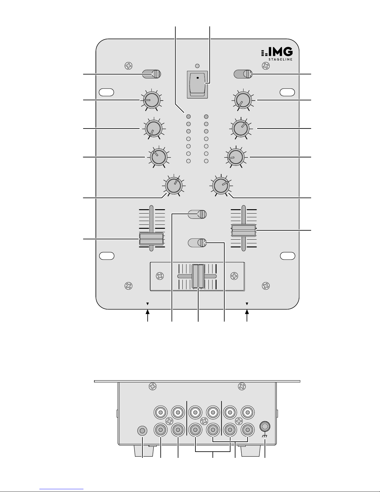
1 7fache LED-Pegelanzeige
2 Ein- /Ausschalter mit Betriebsanzeige
3
Eingangsumschalter PHONO – CD / LINE für die
Kanäle 1 und 2
4
Regler GAIN zum Einstellen der Eingangsverstärkung
für die Kanäle 1 und 2
5 Höhenregler für die Kanäle 1 und 2
6 Tiefenregler für die Kanäle 1 und 2
7 Lautstärkeregler für das Mikrofon
8
Lautstärkeregler für den Kopfhörer an der Buchse
PHONES (14)
9 Lautstärkeregler (Fader) für die Kanäle 1 und 2
10
6,3-mm-Klinkenbuchse für den Anschluss eines
Mono-Mikrofons
11 Schalter für die Vorhörfunktion:
Je nach Stellung des Schalters lässt sich der Kanal 1
oder der Kanal 2 über den Kopfhörer an der Buchse
PHONES (14) abhören.
12
Überblendregler (Crossfader) zum Überblenden zwischen den Kanälen 1 und 2
13 Schalter für Mikrofondurchsagen:
In Position ON werden die Pegel der Kanäle 1 und2
um 16 dB abgesenkt.
14
6,3-mm-Klinkenbuchse zum Anschluss eines Stereo-Kopfhörers (Impedanz ≥ 8 Ω)
1.2 Rückseite
15
3,5-mm-Klinkenbuchse zum Anschluss des beiliegenden Steckertrafos
16
Cinch-Ausgangsbuchsen REC für den Anschluss
eines Tonaufnahmegerätes
17
Cinch-Ausgangsbuchsen AMP für den Anschluss
eines Verstärkers
18
Cinch-Eingangsbuchsen CD / LINE für die Kanäle 1
und2 zum Anschluss von Geräten mit Line- Pegel
(z. B. CD / MP3-Spieler)
19
Cinch-Eingangsbuchsen PHONO für die Kanäle
1und 2 zum Anschluss von Plattenspielern mit Magnetsystem
20
Anschluss GND für einen gemeinsamen Massepunkt,
z. B. für Plattenspieler
2 Hinweise für den sicheren Gebrauch
Die Geräte (Mischpult und Steckertrafo) entsprechen
allen relevanten Richtlinien der EU und sind deshalb mit
gekennzeichnet.
WARNUNG
Der Steckertrafo wird mit lebensgefährlicher Netzspannung versorgt. Nehmen
Sie deshalb niemals selbst Eingriffe am
Steckertrafo vor. Durch unsachgemäßes
Vorgehen besteht die Gefahr eines elektrischen Schlages.
•
Verwenden Sie die Geräte nur im Innenbereich.
Schützen Sie sie vor Tropf- und Spritzwasser, hoher
Luftfeuchtigkeit und Hitze (zulässiger Einsatztemperaturbereich 0 – 40 °C).
•
Stellen Sie keine mit Flüssigkeit gefüllten Ge fäße z. B.
Trinkgläser, auf die Geräte.
•
Auch wenn das Mischpult ausgeschaltet ist, hat der
Steckertrafo einen geringen Stromverbrauch.
•
Nehmen Sie das Mischpult nicht in Betrieb und ziehen
Sie den Steckertrafo sofort aus der Steckdose,
1.
wenn sichtbare Schäden am Mischpult oder am
Steckertrafo vorhanden sind,
2.
wenn nach einem Sturz oder Ähnlichem der Verdacht auf einen Defekt besteht,
3. wenn Funktionsstörungen auftreten.
Geben Sie die Geräte in jedem Fall zur Reparatur in
eine Fachwerkstatt.
•
Verwenden Sie zum Reinigen nur ein trockenes, weiches Tuch, niemals Wasser oder Chemikalien.
•
Werden die Geräte zweckentfremdet, nicht richtig
angeschlossen, falsch bedient oder nicht fachgerecht
repariert, kann keine Haftung für daraus resultierende
Sach- oder Personenschäden und keine Garantie für
die Geräte übernommen werden.
Sollen die Geräte endgültig aus dem Betrieb
genommen werden, übergeben Sie sie zur
umweltgerechten Entsorgung einem örtlichen
Recyclingbetrieb.
3 Einsatzmöglichkeiten
Das Mischpult MPX-1/ BK mit zwei Stereo-Eingangskanälen und einem DJ-Mikrofonanschluss ist für beliebige DJ-Anwendungen im privaten oder professionellen
Bereich geeignet. Es kann sowohl frei aufgestellt als auch
in einen Tisch eingebaut werden.
4 Inbetriebnahme
1)
Die Tonquellen an die entsprechenden Eingangsbuchsen anschließen:
– Buchsen CD / LINE (18) für den Anschluss von Ge-
räten mit Line-Pegel (z. B. Tuner, CD / MP3-Spieler,
Kassettenrecorder)
– Buchsen PHONO (19) für den Anschluss von Platten-
spielern mit Magnetsystem
– Buchse DJ MIC (10) für den Anschluss eines DJ-Mo-
no-Mikrofons

5
Deutsch
2)
Die Eingangsumschalter (3) für die Kanäle 1 und 2 auf
die entsprechende Position stellen.
3)
Den Verstärker an die Ausgangsbuchsen AMP (17)
anschließen.
4) Für eventuelle Tonaufnahmen ein Aufnahmegerät an
die Ausgangsbuchsen REC (16) anschließen.
5)
Den beiliegenden Steckertrafo mit der Buchse „12 V~“
(15) verbinden und anschließend an eine Steckdose
(230 V/ 50 Hz) anschließen.
6)
Vor dem Einschalten des Mischpultes sollten die Kanalfader (9) und der Mikrofon-Lautstärkeregler (7) auf
Minimum gestellt werden, um starke Einschaltgeräusche zu vermeiden. Dann das Mischpult mit dem
Schalter (2) einschalten. Zur Anzeige der Betriebsbereitschaft leuchtet die LED über dem Schalter.
7) Die angeschlossenen Geräte einschalten.
5 Bedienung
Vor der ersten Inbetriebnahme die Klangregler (5und6)
und den Crossfader (12) auf Mittelposition und den Talkover-Schalter (13) auf OFF stellen.
VORSICHT
Stellen Sie die Lautstärke der Audio anlage
und die Kopfhörerlautstärke nie sehr hoch
ein. Hohe Lautstärken können auf Dauer
das Gehör schädigen! Das Ohr gewöhnt
sich an hohe Lautstärken und empfindet
sie nach einiger Zeit als nicht mehr so
hoch. Darum erhöhen Sie eine hohe Lautstärke nach der Gewöhnung nicht weiter.
5.1 Mischen der Tonquellen
1)
Mit den Fadern (9) die Lautstärke für die Eingangskanäle 1 und 2 und mit dem Regler DJ MIC (7) die
Lautstärke für das an der Buchse DJ MIC (10) angeschlossene DJ-Mikrofon einstellen. Der Stereo-Ausgangspegel wird von der 7fachen LED-Pegelanzeige (1)
angezeigt. Bei 0 dB ist das Mischpult voll ausgesteuert.
Übersteuerungen zeigt die Pegelanzeige durch Aufleuchten der roten LEDs an.
Die Fader der Kanäle 1 und 2 sollten nach der
Pegeleinstellung auf ca. 2 ⁄ 3 des Maximums stehen,
damit beim Ein- und Ausblenden genügend Reglerweg vorhanden ist. Sind die Fader wenig oder sehr
weit aufgezogen, müssen die Pegel durch Regulieren der Eingangsverstärkung angepasst werden: Die
GAIN-Regler (4) entsprechend zurückdrehen bzw.
aufdrehen.
2)
Mit den Höhenreglern TREBLE (5) und den Tiefenreglern BASS (6) jeweils für die Kanäle 1 und 2 das
gewünschte Klangbild einstellen: Die Höhen und Tiefen lassen sich bis zu 12 dB anheben bzw. absenken.
Stehen die Regler in Mittelstellung, findet keine Frequenzgangbeeinflussung statt.
3) Mit dem Crossfader (12) kann zwischen den Kanälen
1 und 2 übergeblendet werden. Steht der Crossfader
in Mittelstellung, werden beide Kanäle gleichzeitig auf
die Ausgänge gegeben.
5.2 Vorhören der Kanäle
Über die Vorhörfunktion ist es möglich, die Eingangskanäle 1 und 2 einzeln über einen Kopfhörer abzuhören.
Der Pegel des abgehörten Signals ist unabhängig von
der Stellung des dazugehörigen Kanalfaders. Durch das
Abhören eines Eingangskanals kann somit der günstigste
Zeitpunkt zum Einblenden der entsprechenden Tonquelle
gewählt werden.
1)
Einen Stereo-Kopfhörer (Impedanz ≥ 8 Ω) an die
Buchse PHONES (14) anschließen.
2) Mit dem Umschalter PFL (11) den Kanal 1 oder 2 anwählen.
3)
Mit dem Regler PFL (8) die gewünschte Kopfhörerlautstärke einstellen.
5.3 Durchsagen über das DJ-Mikrofon
Zur besseren Verständlichkeit einer Mikrofondurchsage
können die Pegel der Kanäle 1 und 2 um 16 dB abgesenkt werden. Dazu den Schalter TALK (13) auf Position
ON schieben.
In Position OFF ist die Talkover-Funktion abgeschaltet.
6 Technische Daten
Eingänge
1 × DJ MIC, Mono: . . . . . 1,5 mV/ 600 Ω
2 × PHONO, Stereo: . . . . 3 mV/ 50 kΩ
2 × CD / LINE, Stereo: . . . . 150 mV/ 50 kΩ
Ausgänge
1 × AMP: . . . . . . . . . . . . 1 V/ 600 Ω
1 × REC: . . . . . . . . . . . . . 0,5 V/ 600 Ω
Allgemein
Frequenzbereich: . . . . . . 20 – 20 000 Hz
Klirrfaktor: . . . . . . . . . . . 0,1 %
Störabstand: . . . . . . . . . . CD / LINE 61 dB
PHONO 56 dB
DJ MIC 49 dB
Klangregelung: . . . . . . . . 2 × BASS ±12 dB / 50 Hz
2 × TREBLE ±12 dB /10 kHz
Talkover: . . . . . . . . . . . . . –16 dB
Kopfhörerausgang: . . . . . ≥ 8 Ω, Stereo
Stromversorgung: . . . . . . ~ 12 V über beiliegenden
Steckertrafo an 230 V/ 50 Hz
Abmessungen (B × H × T ): 164 × 77 × 218 mm
Gewicht: . . . . . . . . . . . . . 1,2 kg
Anschlüsse
Mikrofon: . . . . . . . . . . . . 1 × 6,3-mm-Klinke
Kopfhörer: . . . . . . . . . . . 1 × 6,3-mm-Klinke
Alle anderen
Audioanschlüsse: . . . . . . 12 × Cinch
Stromversorgung: . . . . . . 3,5-mm-Klinke
Änderungen vorbehalten.
Diese Bedienungsanleitung ist urheberrechtlich für MONACOR ®
INTERNATIONAL GmbH & Co. KG geschützt. Eine Reproduktion
für eigene kommerzielle Zwecke – auch auszugsweise – ist
untersagt.

6
English
Stereo DJ Mixer
These operating instructions are intended for users with
basic knowledge in audio technology. Please read the
instructions carefully prior to operating the unit and keep
them for later reference.
All operating elements and connections described
can be found on the fold-out page 3.
1 Operating Elements and
Connections
1.1 Front panel
1 7-step LED level indication
2 On /off switch with POWER indicator
3 Input selector switches PHONO – CD / LINE for the
channels 1 and 2
4 GAIN controls to adjust the input amplification for
the channels 1 and 2
5 Treble controls for channels 1 and 2
6 Bass controls for channels 1 and 2
7 Volume control for the microphone
8
Volume control for the headphones connected to
the PHONES jack (14)
9 Volume controls (faders) for the channels 1 and 2
10 6.3 mm jack to connect a mono microphone
11 Switch for the monitoring function:
according to the setting of the switch, channel 1 or
channel 2 can be monitored via headphones connected to the PHONES jack (14)
12 Crossfader for fading between channels 1 and 2
13 Switch for microphone announcements:
with the switch in ON position, the levels of the
channels 1and 2 are decreased by 16 dB
14 6.3 mm jack to connect stereo headphones (imped-
ance ≥ 8 Ω)
1.2 Rear panel
15 3.5 mm jack to connect the supplied plug-in trans-
former
16 RCA output jacks REC to connect a recorder
17 RCA output jacks AMP to connect an amplifier
18 RCA input jacks CD / LINE for the channels 1 and 2
to connect units with line level (e. g. CD / MP3 player)
19 RCA input jacks PHONO for the channels 1 and 2 to
connect turntables with magnet system
20
GND connection for a common ground, e. g. for
turntables
2 Safety Notes
The units (mixer and plug-in transformer) correspond to
all relevant directives of the EU and are therefore marked
with .
WARNING
The plug-in transformer uses dangerous
mains voltage. Leave servicing to skilled
personnel only. Inexpert handling may
result in electric shock.
•
The mixer and the plug-in transformer are suitable for
indoor use only. Protect them against dripping water
and splash water, high air humidity and heat (admissible ambient temperature range 0 – 40 °C).
•
Do not place any vessel filled with liquid on the units,
e. g. a drinking glass.
•
The plug-in transformer has a small power consumption even if the mixer is switched off.
•
Do not take the mixer into operation and immediately
disconnect the plug-in transformer from the mains
socket:
1.
if there is visible damage to the mixer or to the
plug-in transformer,
2. if a defect might have occurred after the unit was
dropped or suffered a similar accident,
3. if there are malfunctions.
The mixer resp. the plug-in transformer must in any
case be repaired by skilled personnel.
•
Only use a dry, soft cloth for cleaning; never use chemicals or water.
•
No guarantee claims for the units and no liability for
any resulting personal damage or material damage
will be accepted if the units are used for other purposes than originally intended, if they are not correctly
connected or operated, or if they are not repaired in
an expert way.
If the units are to be put out of operation
definitively, take them to a local recycling
plant for a disposal which is not harmful to
the environment.
3 Applications
The mixer MPX-1/ BK with two stereo input channels and
one DJ microphone connection is suitable for various DJ
applications for private or professional use. It may be used
as a table top unit or be installed into a table.
4 Setting Into Operation
1)
Connect the audio sources to the corresponding input
jacks:
– CD / LINE jacks (18) to connect units with line level
(e. g. tuner, CD / MP3 player, tape recorder)
– PHONO jacks (19) to connect turntables with mag-
net system
– DJ MIC jack (10) to connect a DJ mono microphone
2)
Set the input selector switches (3) for channels 1 and2
to the corresponding position.

7
English
3) Connect the amplifier to the output jacks AMP (17).
4)
Connect a recorder to the output jacks REC (16) if
audio recordings are desired.
5) Connect the supplied plug-in transformer to the jack
“12 V~” (15) and then to a mains socket (230 V/ 50 Hz).
6) Before switching on the mixer, the channel faders (9)
and the microphone volume control (7) should be set
to minimum to avoid loud switching noises. Then,
switch on the mixer with the switch (2). The LED above
the switch lights to indicate operation.
7) Switch on the connected units.
5 Operation
Before taking the mixer into operation for the first time,
set the tone controls (5 and 6) as well as the crossfader
(12) to center position and the talkover switch (13) to OFF.
CAUTION
Never adjust the audio system or the
headphones to a very high volume. Permanent high volumes may damage your
hearing! Your ear will get accustomed to
high volumes which do not seem to be
that high after some time. Therefore, do
not further increase a high volume after
getting used to it.
5.1 Mixing of the audio sources
1) Adjust the volume of the input channels 1 and 2 with
the faders (9) and the volume of the DJ microphone
connected to the DJ MIC jack (10) with the DJ MIC
control (7). The stereo output level is indicated by the
7-step LED level indication (1). At 0 dB, the mixer is
at its rated maximum output. In case of overload, the
red LEDs of the level indication will light up.
The faders of the channels 1 and 2 should be
at approx. 2 ⁄ 3 of the maximum after the level adjustment so that there is sufficient control range for fading
in and out. If the faders are almost at minimum or
maximum position, the levels have to be matched by
adjusting the input amplification: Turn back resp. turn
up the GAIN controls (4) correspondingly.
2) Adjust the desired sound characteristic for channels
1 and 2 with the TREBLE controls (5) and the BASS
controls (6): The high and low frequencies can be
increased resp. decreased by 12 dB. The frequency
response is not affected if the controls are in center
position.
3) Fading between the channels 1 and 2 is possible via
the crossfader (12). If the crossfader is in center position, both channels are fed to the outputs simul
-
taneously.
5.2 Monitoring of the channels
Via the monitoring function, it is possible to monitor the
input channels 1 and 2 individually via headphones. The
level of the monitored signal is independent of the setting of the corresponding channel fader. By monitoring
of an input channel, the best moment for fading in the
corresponding audio source can be selected.
1)
Connect stereo headphones (impedance ≥ 8 Ω) to the
PHONES jack (14).
2)
Select the channel 1 or 2 with the selector switch
PFL (11).
3) Adjust the desired headphones volume with the PFL
control (8).
5.3 Annoucements via the DJ microphone
For better intelligibility of a microphone announcement,
the levels of the channels 1 and 2 can be decreased by
16 dB. Set the TALK switch (13) to position ON.
The talkover function is deactivated in the OFF position.
6 Specifications
Inputs
1 × DJ MIC, mono: . . . . . 1.5 mV/ 600 Ω
2 × PHONO, stereo: . . . . 3 mV/ 50 kΩ
2 × CD / LINE, stereo: . . . . 150 mV/ 50 kΩ
Outputs
1 × AMP: . . . . . . . . . . . . 1 V/ 600 Ω
1 × REC: . . . . . . . . . . . . . 0.5 V/ 600 Ω
General
Frequency range: . . . . . . 20 – 20 000 Hz
THD: . . . . . . . . . . . . . . . . 0.1 %
S / N ratio: . . . . . . . . . . . . CD / LINE 61 dB
PHONO 56 dB
DJ MIC 49 dB
Equalizer: . . . . . . . . . . . . 2 × BASS ±12 dB / 50 Hz
2 × TREBLE ±12 dB /10 kHz
Talkover: . . . . . . . . . . . . . –16 dB
Headphones output: . . . . ≥ 8 Ω, stereo
Power supply: . . . . . . . . . ~ 12 V via supplied plug-in
transformer connected to
230 V/ 50 Hz
Dimensions (W × H × D): 164 × 77 × 218 mm
Weight: . . . . . . . . . . . . . 1.2 kg
Connections
Microphone: . . . . . . . . . . 1 × 6.3 mm jack
Headphones: . . . . . . . . . 1 × 6.3 mm jack
All other
audio connections: . . . . . 12 × RCA
Power supply: . . . . . . . . . 3.5 mm jack
Subject to technical modification.
All rights reserved by MONACOR ® INTERNATIONAL GmbH &
Co. KG. No part of this instruction manual may be reproduced
in any form or by any means for any commercial use.
8
Français
Table de mixage stéréo DJ
Cette notice s’adresse aux utilisateurs avec des connaissances techniques de base en audio. Veuillez lire la présente notice avec attention avant le fonctionnement et
conservez-la pour pouvoir vous y reporter ultérieurement.
Vous trouverez sur la page 3, dépliable, les éléments
et branchements décrits.
1 Eléments et branchements
1.1 Face avant
1 VU-mètre à LEDs, 7 niveaux
2
Interrupteur Marche /Arrêt avec témoin de fonctionnement
3 Sélecteurs d‘entrée PHONO – CD / LINE pour les ca-
naux 1 et 2
4
Potentiomètres GAIN : réglage de l‘amplification
d‘entrée pour les canaux 1 et 2
5
Potentiomètres de réglage des aigus pour les canaux 1 et 2
6 Potentiomètres de réglage des graves pour les ca-
naux 1 et 2
7
Potentiomètre de réglage du volume pour le microphone
8
Potentiomètre de réglage du volume pour le casque
relié à la prise PHONES (14)
9 Potentiomètres de réglage du volume pour les ca-
naux 1 et 2
10 Prise jack 6,35 pour brancher un microphone mono
11
Interrupteur pour la fonction préécoute : selon la
position de l‘interrupteur, vous pouvez effectuer une
préécoute du canal 1 ou du canal 2 dans un casque
relié à la prise PHONES (14)
12 Potentiomètre de fondu-enchaîné entre les canaux
1 et 2.
13 Interrupteur pour des annonces micro ; en position
ON, le niveau des canaux 1 et 2 est diminué de 16 dB
14 Prise jack 6,35 : permet de brancher un casque sté-
réo, impédance ≥ 8 Ω
1.2 Face arrière
15 Prise jack 3,5 : branchement du bloc secteur livré
16
Prises de sortie RCA REC : branchement d‘un magnétophone pour effectuer des enregistrements
17 Prises de sortie RCA AMP : branchement d‘un am-
plificateur
18
Prises d‘entrée RCA CD / LINE pour les canaux
1 et2: branchement d‘appareils à niveau Ligne
(parexemple, lecteur CD/MP3)
19
Prises d‘entrée RCA PHONO pour les canaux
1 et2: branchement de platines-disques à cellule
magnétique
20
Branchement GND pour une masse commune,
parexemple, pour platine-disque
2 Conseils d‘utilisation
Les appareils (table de mixage et le bloc secteur) répondent à toutes les directives nécessaires de l’Union
européenne et portent donc le symbole .
AVERTISSEMENT Le bloc secteur est alimenté par une
tension dangereuse. Ne touchez jamais l’intérieur de l’appareil car, en cas
de mauvaise manipulation, vous pourriez subir une décharge électrique.
•
La table de mixage et le bloc secteur ne sont conçus
que pour une utilisation en intérieur. Protégez-les de
tout type de projections d’eau, des éclaboussures,
d’une humidité élevée et la chaleur (plage de température de fonctionnement autorisée : 0 – 40 °C).
•
En aucun cas, vous ne devez pas poser d’objet contenant du liquide ou un verre sur les appareils.
•
Même lorsque la table de mixage est éteinte, le bloc
secteur a une faible consommation.
•
Ne faites pas fonctionner la table de mixage et débranchez immédiatement le bloc secteur lorsque :
1.
des dommages sur la table de mixage ou le bloc
secteur apparaissent.
2. après une chute ou accident similaire, vous avez un
doute sur l’état de l’appareil.
3. des dysfonctionnements apparaissent.
Dans tous les cas, les dommages doivent être réparés
par un technicien spécialisé.
•
Pour nettoyer les appareils, utilisez uniquement un chiffon sec et doux, en aucun cas, de produits chimiques
ou d’eau.
•
Nous déclinons toute responsabilité en cas de dommages corporels ou matériels résultants si les appareils
sont utilisés dans un but autre que celui pour lequel ils
ont été conçus, s’ils ne sont pas correctement branchés
ou utilisés ou s’ils ne sont pas réparés par une personne
habilitée ; en outre, la garantie deviendrait caduque.
Lorsque les appareils sont définitivement retirés du service, vous devez les déposer dans
une usine de recyclage adaptée pour contribuer à leur élimination non polluante.
CARTONS ET EMBALLAGE
PAPIER À TRIER
3 Possibilités d‘utilisation
La table de mixage MPX-1/ BK est dotée de deux canaux d’entrée stéréo et d‘un branchement micro DJ,
permettant ainsi une utilisation par un DJ amateur ou
professionnel. Elle peut être posée directement sur une
table ou encastrée.
4 Utilisation
1) Reliez les sources aux entrées correspondantes :
– prises CD / LINE (18) : branchement d‘appareils à
 Loading...