

IMG STAGE LINE MPX-1 Instruction Manual
BEDIENUNGSANLEITUNG • INSTRUCTION MANUAL • MODE D’EMPLOI
ISTRUZIONI PER L’USO • GEBRUIKSAANWIJZING • HANDLEIDING
MANUAL DE INSTRUCCIONES • MANUAL DE INSTRUÇÕES
BRUGSANVISNING • BRUKSANVISNING • KÄYTTÖOHJE
STEREO-DJ-MISCHPULT
STEREO DJ MIXER
TABLE DE MIXAGE DJ STEREO
MIXER DJ STEREO
2-CHANNEL
PRO SOUND
MIXER
CH1
GAIN
MAXMIN
PHONO / LINE
TREBLE
–15
+15
BASS
–15
+15
DJ MIC
100
GAIN
MAXMIN
TREBLE
–15
+15
BASS
–15
+15
CH2
PHONO / LINE
PFL
100
LEFT RIGHT
+6
+3
0
–3
–6
–10
–20
+6
+3
0
–3
–6
–10
–20
MPX-1
POWER
CH 1/ CH2
PFL ASSIGN
ON / OFF
TALKOVER
DJ MIC PHONES
OUTPUT LEVEL
CROSS FADER
Modellserie MPX-1
Model series MPX-1

2
Ennen virran kytkemistä ...
Toivomme, että uusi “img Stage Line”-laitteesi
tuo sinulle paljon iloa ja hyötyä. Tämä käyttöohje esittää sinulle kaikki uuden laitteesi toiminnot. Seuraamalla sitä vältät virhetoiminnot
ja niistä johtuvat mahdolliset vahingot sinulle
tai laitteellesi.
Löydät suomenkielisen ohjeen sivuilta 22–23.
FIN
Bevor Sie einschalten ...
Wir wünschen Ihnen viel Spaß mit Ihrem neuen Gerät von „img Stage Line“. Dabei soll
Ihnen diese Bedienungsanleitung helfen, alle
Funktionsmöglichkeiten kennenzulernen. Die
Beachtung der Anleitung vermeidet außerdem Fehlbedienungen und schützt Sie und
Ihr Gerät vor eventuellen Schäden durch unsachgemäßen Gebrauch.
Den deutschen Text finden Sie auf den Seiten
4–5.
D
A
CH
Avant toute mise en service ...
Nous vous remercions d’avoir choisi un appareil “img Stage Line” et vous souhaitons
beaucoup de plaisir à l’utiliser. Cette notice a
pour objectif de vous aider à mieux connaître
les multiples facettes de l’appareil. En outre,
en respectant les conseils donnés, vous éviterez toute mauvaise manipulation de sorte
que vous-même et votre appareil soient protégés de tout dommage.
La version française se trouve pages 8–9.
V oordat u inschakelt ...
Wij wensen u veel plezier met uw nieuw toestel
van “img Stage Line”. Met behulp van bijgaande gebruiksaanwijzing zal u alle functiemogelijkheden leren kennen. Door deze instructies op te volgen zal een slechte werking
vermeden worden, en zal een eventueel letsel
aan uzelf en schade aan uw toestel tengevolge
van onzorgvuldig gebruik worden voorkomen.
U vindt de nederlandstalige tekst op de pagina’s 12–13.
E
Inden De tænder for apparatet ...
Vi ønsker Dem god fornøjelse med Deres nye
“img Stage Line” apparat. Denne brugsanvisning giver mulighed for at lære alle apparatets
funktioner at kende. Følg vejledningen for at
undgå forkert betjening og for at beskytte
Dem og Deres apparat mod skade på grund
af forkert brug.
Den danske tekst finder du på side 18–19.
DK
Before you switch on ...
We wish you much pleasure with your new
“img Stage Line” unit. With these operating
instructions you will be able to get to know all
functions of the unit. By following these instructions false operations will be avoided,
and possible damage to yourself and your
unit due to improper use will be prevented.
You will find the English text on pages 6–7.
Antes de cualquier instalación ...
Tenemos de agradecerle el haber adquirido
un aparato “img Stage Line” y le deseamos
un agradable uso. Este manual quiere ayudarle a conocer las multiples facetas de este
aparato. La observación de las instrucciones
evita operaciones erróneas y protege Vd. y
vuestro aparato contra todo daño posible por
cualquier uso inadecuado.
La versión española se encuentra en las páginas 14–15.
GB
I
S
Prima di accendere ...
Vi auguriamo buon divertimento con il Vostro
nuovo apparecchio “img Stage Line”. Le istruzioni per l’uso Vi possono aiutare a conoscere
tutte le possibili funzioni. E rispettando quanto
spiegato nelle istruzioni, evitate di commettere degli errori, e così proteggete Voi stessi,
ma anche l’apparecchio, da eventuali rischi
per uso improprio.
Il testo italiano lo potete trovare alle pagine
10–11.
Förskrift
Vi önskar dig mycket nöje med din nya “img
Stage Line” enheten. Om du först läser instruktionerna kommer du att glädje av enheten under lång tid. Kunskap om alla funktioner
kan bespara dig mycket besvär med enheten
i framtiden.
Du finner den svenska texten på sidan 20 – 21.
F
B
CH
NL
B
wwwwww..iimmggssttaaggeelliinnee..ccoomm
®
3
12V~
LEFTRIGHT
REC AMP PHONOLINE
LEFTRIGHT
LEFTRIGHT
LEFTRIGHT
PHONOLINE
OUTPUT CH 2 CH 1
GND
15 16 17 18 19 20
2-CHANNEL
PRO SOUND
MIXER
CH1
GAIN
MAXMIN
PHONO / LINE
TREBLE
–15
+15
BASS
–15
+15
DJ MIC
100
GAIN
MAXMIN
TREBLE
–15
+15
BASS
–15
+15
CH2
PHONO / LINE
LEFT RIGHT
+6
+3
0
–3
–6
–10
–20
+6
+3
0
–3
–6
–10
–20
MPX-1
POWER
CH1 / CH2
PFL ASSIGN
ON / OFF
TALKOVER
DJ MIC PHONES
OUTPUT LEVEL
CROSS FADER
DJ MIC
100
PFL
100
12
➀
3 3
4
5
6
7
9
4
5
6
8
9
➁
10 11 12 13 14
MPX-1/CC

D
A
CH
4
Bitte klappen Sie die Seite 3 heraus. Sie sehen
dann immer die beschriebenen Bedienelemente
und Anschlüsse.
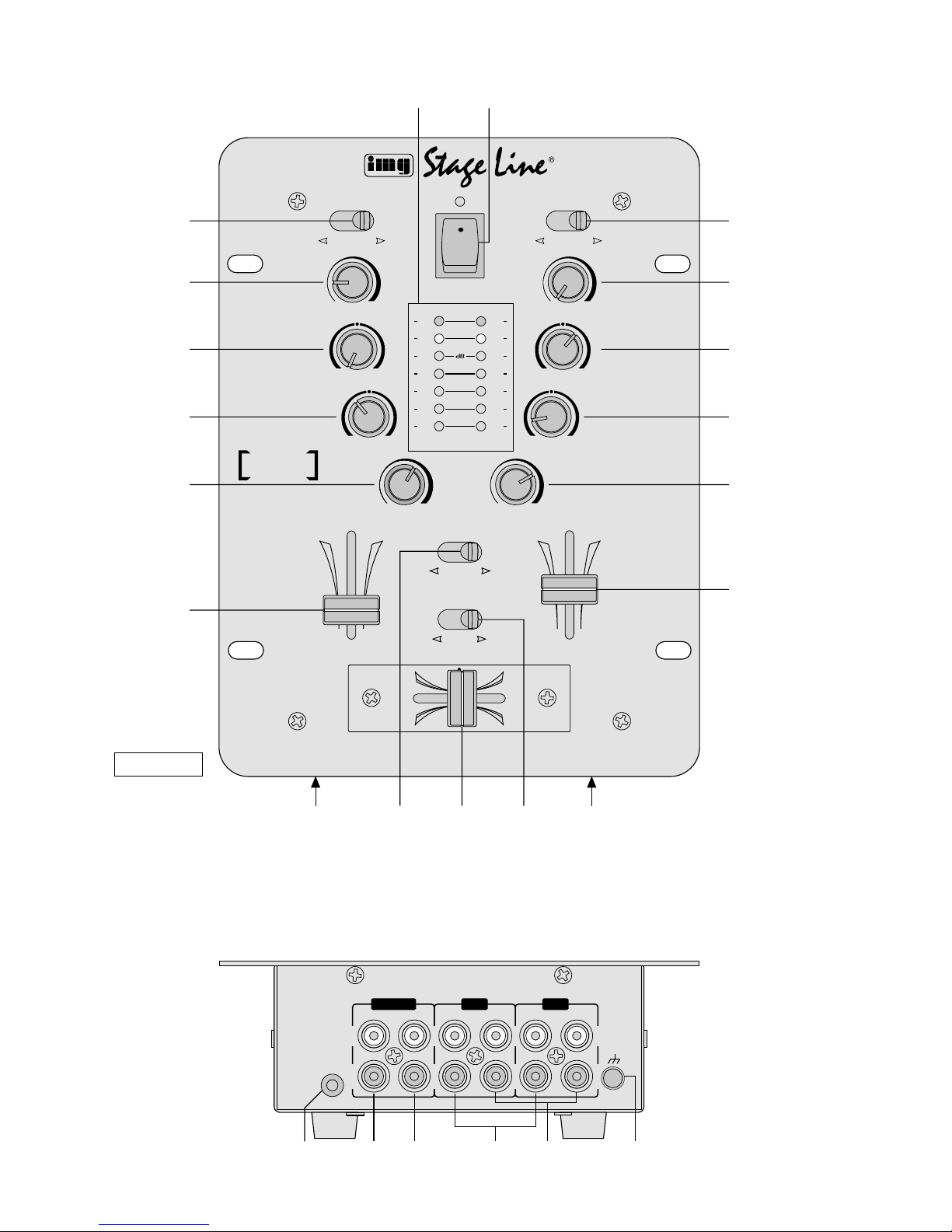
1 Übersicht der Bedienelemente und
Anschlüsse
1.1 Frontseite
1 7fache LED-Pegelanzeige
2 Ein-/Ausschalter mit Betriebsanzeige
3 Eingangsumschalter Phono/Line für die Kanäle
CH1 und CH2
4 Regler GAIN zum Einstellen der Eingangsverstär-
kung für die Kanäle CH1 und CH2
5 Höhenregler für die Kanäle CH1 und CH2
6 Tiefenregler für die Kanäle CH1 und CH2
7 Lautstärkeregler für das Mikrofon
8 Lautstärkeregler für den Kopfhörer an Buchse (14)
9 Lautstärkeregler (Fader) für die Kanäle CH 1 und
CH2
10 6,3-mm-Klinkenbuchse für den Anschluß eines Mo-
no-Mikrofons
11 Schalter für die Vorhörfunktion:
Je nach Stellung des Schalters läßt sich der Kanal
CH1 oder der Kanal CH2 über den Kopfhörer an
Buchse (14) abhören.
12 Überblendregler (Crossfader) zum Überblenden
zwischen den Kanälen CH1 und CH2
13 Schalter für Mikrofondurchsagen:
In Position ON werden die Pegel der Kanäle CH1
und CH2 um 16dB abgesenkt.
14 6,3-mm-Klinkenbuchse zum Anschluß eines Ste-
reo-Kopfhörers (Impedanz ≥ 8Ω)
1.2 Rückseite
15 3,5-mm-Klinkenbuchse zum Anschluß des beilie-
genden Steckertrafos (230V~/50Hz/10VA)
16 Cinch-Ausgangsbuchsen REC für den Anschluß
eines Tonaufnahmegerätes
17 Cinch-Ausgangsbuchsen AMP für den Anschluß
eines Verstärkers
18 Cinch-Eingangsbuchsen LINE für die Kanäle CH1
und CH2 zum Anschluß von Geräten mit Line-Pegel (z.B. Tuner, CD-Spieler, Kassettenrecorder)
19 Cinch-Eingangsbuchsen PHONO für die Kanäle
CH1 und CH2 zum Anschluß von Plattenspielern
mit Magnetsystem
20 Anschluß GND für einen gemeinsamen Masse-
punkt, z.B. für Plattenspieler
2 Hinweise für den sicheren Gebrauch
Das Gerät und der Steckertrafo entsprechen der Richtlinie für elektromagnetische Verträglichkeit 89/336/
EWG. Der Steckertrafo entspricht zusätzlich der Niederspannungsrichtlinie 73/23/EWG.
Beachten Sie auch unbedingt die folgenden Punkte:
●
Verwenden Sie das Mischpult und den Steckertrafo
nur im Innenbereich. Schützen Sie die Geräte vor
Tropf- und Spritzwasser, hoher Luftfeuchtigkeit und
Hitze (zulässiger Einsatztemperaturbereich 0°C bis
40°C).
●
Auch wenn das Gerät ausgeschaltet ist, hat der
Steckertrafo einen geringen Stromverbrauch.
●
Das Gerät nicht in Betrieb nehmen, und den Stekkertrafo sofort aus der Steckdose ziehen, wenn:
1. sichtbare Schäden am Gerät oder am Steckertrafo vorhanden sind,
2. nach einem Sturz oder ähnlichem der Verdacht
auf einen Defekt besteht,
3. Funktionsstörungen auftreten.
Das Gerät bzw. den Steckertrafo in jedem Fall zur
Reparatur in eine Fachwerkstatt geben.
●
Für die Reinigung nur ein trockenes, weiches Tuch
verwenden, auf keinen Fall Wasser oder Chemikalien.
●
Wird das Gerät bzw. der Steckertrafo zweckentfremdet, nicht richtig angeschlossen, falsch bedient oder
nicht fachgerecht repariert, kann für eventuelle Schäden keine Haftung übernommen werden.
●
Sollen das Gerät und der Steckertrafo endgültig aus
dem Betrieb genommen werden, übergeben Sie sie
zur Entsorgung einem örtlichen Recyclingbetrieb.
3 Einsatzmöglichkeiten
Das Stereo-Disco-Mischpult MPX-1 mit zwei StereoEingangskanälen und einem DJ-Mikrofonanschluß ist
für beliebige DJ-Anwendungen im privaten oder professionellen Bereich geeignet. Es kann sowohl frei aufgestellt als auch in einen Tisch eingebaut werden.
4 Inbetriebnahme
1) Die Tonquellen an die entsprechenden Eingangsbuchsen anschließen:
-
Buchsen LINE (18) für den Anschluß von Geräten mit Line-Pegel (z.B. Tuner, CD-Spieler, Kassettenrecorder)
-
Buchsen PHONO (19) für den Anschluß von
Plattenspielern mit Magnetsystem
-
Buchse DJ MIC (10) für den Anschluß eines DJMono-Mikrofons
2) Die Eingangsumschalter (3) für die Kanäle CH 1
und CH2 auf die entsprechende Position stellen.
Achtung! Der Steckertrafo wird mit lebensgefährli-
cher Netzspannung (230V~) versorgt.
Nehmen Sie deshalb nie selbst Eingriffe
im Steckertrafo vor. Durch unsachgemäßes Vorgehen besteht die Gefahr eines
elektrischen Schlages. Außerdem erlischt
beim Öffnen des Steckertrafos oder des
Gerätes jeglicher Garantieanspruch.

D
A
CH
5
3) Den Verstärker an die Ausgangsbuchsen AMP (17)
anschließen.
4) Für eventuelle Tonaufnahmen ein Aufnahmegerät
an die Ausgangsbuchsen REC (16) anschließen.
5) Den beiliegenden Steckertrafo mit der Buchse (15)
verbinden und anschließend an eine Steckdose
(230V~/50Hz) anschließen.
6) Vor dem Einschalten des Mischpultes sollten die
Kanalfader (9) und der Mikrofon-Lautstärkeregler
(7) auf Minimum gestellt werden, um starke Einschaltgeräusche zu vermeiden. Dann das Mischpult mit dem Schalter (2) einschalten. Zur Anzeige
der Betriebsbereitschaft leuchtet die LED über dem
Schalter.
7) Die angeschlossenen Geräte einschalten.
5 Bedienung
Vor der ersten Inbetriebnahme die Klangregler (5 und
6) und den Crossfader (12) auf Mittelposition und den
Talkover-Schalter (13) auf OFF stellen.
5.1 Mischen der angeschlossenen Tonquellen
1) Mit den Fadern (9) die Lautstärke für die Eingangskanäle CH1 und CH2 und mit dem Regler DJ MIC
(7) die Lautstärke für das an Buchse (10) angeschlossene DJ-Mikrofon einstellen. Der StereoAusgangspegel wird von der 7fachen LED-Pegelanzeige (1) angezeigt. Bei 0 dB ist das Mischpult
voll ausgesteuert. Übersteuerungen zeigt die Pegelanzeige durch Aufleuchten der roten LEDs an.
Die Fader der Kanäle CH1 und CH2 sollten
nach der Pegeleinstellung auf ca.
2
/3 des Maximums stehen, damit beim Ein- und Ausblenden genügend Reglerweg vorhanden ist. Sind die Fader
wenig oder sehr weit aufgezogen, müssen die Pegel durch Regulieren der Eingangsverstärkung angepaßt werden: Die GAIN-Regler (4) entsprechend
zurückdrehen bzw. aufdrehen.
2) Mit den Höhenreglern TREBLE (5) und den Tiefenreglern BASS (6) jeweils für die Kanäle CH 1 und
CH2 das gewünschte Klangbild einstellen: Die Höhen und Tiefen lassen sich bis zu 12 dB anheben
bzw. absenken. Stehen die Regler in Mittelstellung,
findet keine Frequenzgangbeeinflussung statt.
3) Mit dem Crossfader (12) kann zwischen den Kanälen CH 1 und CH2 übergeblendet werden. Steht
der Crossfader in Mittelstellung, werden beide Kanäle gleichzeitig auf die Ausgänge gegeben.
5.2 Vorhören der Kanäle
Über die Vorhörfunktion ist es möglich, die Eingangskanäle CH 1 und CH 2 einzeln über einen Kopfhörer
abzuhören. Der Pegel des abgehörten Signals ist unabhängig von der Stellung des dazugehörigen Kanalfaders. Durch das Abhören eines Eingangskanals
kann somit der günstigste Zeitpunkt zum Einblenden
der entsprechenden Tonquelle gewählt werden.
1) Einen Stereo-Kopfhörer (Impedanz ≥ 8Ω) an die
Buchse PHONES (14) anschließen.
2) Mit dem Umschalter PFL ASSIGN (11) den Kanal
CH 1 oder CH2 anwählen.
3) Mit dem Regler PFL (8) die gewünschte Kopfhörerlautstärke einstellen.
5.3 Durchsagen über das DJ-Mikrofon
Zur besseren Verständlichkeit einer Mikrofondurchsage können die Pegel der Kanäle CH 1 und CH 2 um
16 dB abgesenkt werden. Dazu den Schalter TALKOVER (13) auf Position ON schieben.
In Position OFF ist die Talkover-Funktion abgeschaltet.
6 Technische Daten
Eingänge
1 x Mic, Mono: . . . . . . . . . . . 1,5mV/600 Ω
2 x Phono, Stereo:. . . . . . . . 3mV/50kΩ
2 x Line, Stereo:. . . . . . . . . . 150mV/50kΩ
Ausgänge
1 x Amp:. . . . . . . . . . . . . . . . 1V/600Ω
1 x Record: . . . . . . . . . . . . . 0,5V/600 Ω
Allgemein
Frequenzbereich:. . . . . . . . . 20
-
20000Hz
Klirrfaktor: . . . . . . . . . . . . . . 0,1%
Störabstand
Line:. . . . . . . . . . . . . . . . . 61dB
Phono: . . . . . . . . . . . . . . . 56dB
Mic: . . . . . . . . . . . . . . . . . 49dB
Klangregelung
2 x Tiefen: . . . . . . . . . . . . ±12dB/50Hz
2 x Höhen: . . . . . . . . . . . . ±12dB/10kHz
Talkover: . . . . . . . . . . . . . . . -16dB
Kopfhörerausgang: . . . . . . . ≥ 8 Ω, Stereo
Stromversorgung: . . . . . . . . 12V~/600 mA über bei-
liegenden Steckertrafo
(230V~/50Hz/10VA)
Zulässige
Einsatztemperatur:. . . . . . . . 0
-
40°C
Abmessungen (B x H x T):. . 164 x 77 x 218mm
Gewicht:. . . . . . . . . . . . . . . . 1,2kg
Anschlüsse
Mic: . . . . . . . . . . . . . . . . . . . 1 x 6,3-mm-Klinke
Kopfhörer: . . . . . . . . . . . . . . 1 x 6,3-mm-Klinke
Alle anderen
Audioanschlüsse:. . . . . . . . . 12 x Cinch
Stromversorgung: . . . . . . . . 3,5-mm-Klinke
Laut Angaben des Herstellers.
Änderungen vorbehalten.
Achtung! Stellen Sie die Kopfhörerlautstärke
nie sehr hoch ein. Hohe Lautstärken
können auf Dauer das Gehör schädigen! Das menschliche Ohr gewöhnt
sich an große Lautstärken und empfindet sie nach einiger Zeit als nicht
mehr so hoch. Darum eine hohe
Lautstärke nach der Gewöhnung nicht
weiter erhöhen.

GB
6
Please unfold page 3. Then you can always see the
operating elements and connections described.
1 Operating Elements and Connections
1.1 Front panel
1 7-step LED level display
2 On/off switch with operating indication
3 Input selector switches phono/line for the channels
CH1 and CH2
4 GAIN controls to adjust the input amplification for
the channels CH1 and CH2
5 Treble controls for channels CH1 and CH2
6 Bass controls for channels CH1 and CH2
7 Volume control for the microphone
8 Volume control for the headphones connected to
the jack (14)
9 V olume controls (faders) for the channels CH1 and
CH2
10 6.3mm (
1
/4") jack to connect a mono microphone
11 Switch for the monitoring function: according to the
setting of the switch, channel CH1 or channel CH2
can be monitored via headphones connected to the
jack (14)
12 Crossfader for fading between channels CH1 and
CH2
13 Switch for microphone announcements: with the
switch in ON position, the levels of the channels
CH 1 and CH2 are decreased by 16dB
14 6.3 mm (
1
/4") jack to connect stereo headphones
(impedance ≥ 8Ω)
1.2 Rear panel
15 3.5mm jack to connect the supplied plug-in trans-
former (230V~/50Hz/10VA)
16 Phono output jacks REC to connect a sound reord-
ing unit
17 Phono output jacks AMP to connect an amplifier
18 Phono input jacks LINE for the channels CH1 and
CH2 to connect units with line level (e.g. tuner, CD
player, tape recorder)
19 Phono input jacks PHONO for the channels CH 1
and CH2 to connect turntables with magnet system
20 GND connection for a common ground, e. g. for
turntables
2 Safety Notes
The unit and the plug-in transformer correspond to the
directive for electromagnetic compatibility 89/ 336/
EEC. The plug-in transformer additionally corresponds
to the low voltage directive 73/23/EEC.
Also watch in any case the following items:
●
The mixer and the plug-in transformer are suitable
for indoor use only. Protect them against dripping
water and splash water, high air humidity and heat
(admissible ambient temperature range 0–40°C).
●
The plug-in transformer has a small power consumption even if the unit is switched off.
●
Do not take the unit into operation and immediately
take the plug-in transformer out of the mains socket:
1. if damage at the unit or transformer can be seen,
2. if a defect might have occurred after a drop or
similar accident,
3. if there are malfunctions.
The unit resp. the plug-in transformer must in any
case be repaired by authorized skilled personnel.
●
Only use a dry, soft cloth for cleaning, by no means
chemicals or water.
●
If the unit or the plug-in transformer is used for purposes other than originally intended, if it is not connected properly, if it is operated in the wrong way or
not repaired by authorized skilled personnel, there is
no liability for possible damage.
●
If the unit is to be put out of operation definitively,
bring it to a local recycling plant for disposal.
3 Applications
The stereo disco mixer MPX-1 with two stereo input
channels and one DJ microphone connection is suitable
for various DJ applications for private or professional
use. It may be used as a table top unit or be installed
into a table.
4 Setting Into Operation
1) Connect the audio sources to the corresponding
input jacks:
-
LINE jacks (18) to connect units with line level
(e.g. tuner, CD player, tape recorder)
-
PHONO jacks (19) to connect turntables with
magnet system
-
DJ MIC jack (10) to connect a DJ mono microphone
2) Set the input selector switches (3) for channels
CH1 and CH2 to the corresponding position.
3) Connect the amplifier to the output jacks AMP (17).
4) Connect a recording unit to the output jacks REC
(16) if audio recordings are desired.
5) Connect the supplied plug-in transformer to the jack
(15) and then to a mains socket (230V~/50Hz).
6) Before switching on the mixer, the channel faders
(9) and the microphone volume control (7) should
be set to minimum to avoid loud switching noises.
Then, switch on the mixer with the switch (2). The
LED above the switch lights to indicate operation.
7) Switch on the connected units.
5 Operation
Before taking the mixer into operation for the first time,
set the tone controls (5 and 6) as well as the crossfader (12) to center position and the talkover switch
(13) to OFF.
Attention! The plug-in transformer uses dangerous
mains voltage (230V~). To prevent a shock
hazard, do not open the cabinet. Leave servicing to authorized skilled personnel only.
Any guarantee claim expires if the plug-in
transformer or the unit has been opened.

5.1 Mixing of the connected audio sources
1) Adjust the volume of the input channels CH1 and
CH2 with the faders (9) and the volume of the DJ
microphone connected to the jack (10) with the DJ
MIC control (7). The stereo output level is displayed
by the 7-step LED level display (1). At 0dB the
mixer is at its rated maximum output. Overloads are
indicated via the level display by lighting of the red
LEDs.
The faders of the channels CH1 and CH2 should
be at approx. 2/
3 of the maximum after the level ad-
justment so that there is sufficient control range for
fading in and out. If the faders are almost at minimum or maximum position, the levels have to be
matched by adjusting the input amplification: Turn
up resp. turn back the GAIN controls (4) correspondingly.
2) Adjust the desired sound characteristic for channels
CH 1 and CH 2 with the TREBLE controls (5) and
the BASS controls (6): The high and low frequencies can be increased resp. decreased by 12 dB.
The frequency response is not affected if the controls are in center position.
3) Fading between the channels CH 1 and CH2 is
possible via the crossfader (12). If the crossfader is
in center position, both channels are fed to the outputs simultaneously.
5.2 Monitoring of the channels
Via the monitoring function it is possible to monitor the
input channels CH 1 and CH 2 individually by headphones. The level of the monitored signal is independent of the setting of the corresponding channel fader.
By monitoring of an input channel the best moment for
fading in the corresponding audio source can be selected.
1) Connect stereo headphones (impedance ≥ 8 Ω) to
the PHONES jack (14).
2) Select the channel CH1 or CH2 with the selector
switch PFLASSIGN (11).
3) Adjust the desired headphones volume with the
PFL control (8).
5.3 Annoucements via the DJ microphone
For better intelligibility of a microphone announcement, the levels of the channels CH1 and CH2 can be
decreased by 16dB. Adjust the TALKOVER switch
(13) to position ON.
The talkover function is deactivated in the OFF
position.
6 Specifications
Inputs
1 x mic, mono: . . . . . . . . . . . 1.5mV/ 600Ω
2 x phono, stereo: . . . . . . . . 3 mV/50 kΩ
2 x line, stereo: . . . . . . . . . . 150 mV/50 kΩ
Outputs
1 x amp:. . . . . . . . . . . . . . . . 1V/600Ω
1 x record: . . . . . . . . . . . . . . 0.5 V/600Ω
General
Frequency range:. . . . . . . . . 20
-
20000Hz
THD: . . . . . . . . . . . . . . . . . . 0.1 %
S/N ratio
Line:. . . . . . . . . . . . . . . . . 61dB
Phono: . . . . . . . . . . . . . . . 56dB
Mic: . . . . . . . . . . . . . . . . . 49dB
Equalizer
2 x bass: . . . . . . . . . . . . . ±12dB/50Hz
2 x treble:. . . . . . . . . . . . . ±12 dB/10kHz
Talkover: . . . . . . . . . . . . . . .
-
16dB
Headphones output: . . . . . . ≥ 8 Ω, stereo
Power supply: . . . . . . . . . . . 12V~/600 mA
via supplied plug-in
transformer
(230V~/50Hz/10 VA)
Permissible
operating temperature: . . . . 0
-
40°C
Dimensions (W x H x D): . . . 164 x 77 x 218mm
Weight:. . . . . . . . . . . . . . . . . 1.2 kg
Connections
Mic: . . . . . . . . . . . . . . . . . . . 1 x 6.3mm (
1
/4") jack
Headphones: . . . . . . . . . . . . 1 x 6.3mm (
1
/4") jack
All other audio connections:. 12 x phono
Power supply: . . . . . . . . . . . 3.5mm jack
According to the manufacturer.
Subject to change.
Caution! Do not adjust the headphones to a high
volume. Permanent high volumes may
damage a person´s hearing! The human ear gets accustomed to high volumes which do not seem to be that high
after some time. Therefore, do not further increase a high volume after getting used to it.
GB
7

Ouvrez le présent livret page 3 de manière à visualiser les éléments et branchements.
1 Eléments et branchements
1.1 Face avant
1 VU-mètre à 7 diodes
2 Interrupteur Marche/Arrêt avec témoin de fonction-
nement
3 Sélecteurs d'entrée Phono / Ligne pour les canaux
CH1 et CH2
4 Potentiomètres GAIN: réglage de l'amplification
d'entrée pour les canaux CH1 et CH2
5 Potentiomètres de réglage des aigus pour les ca-
naux CH1 et CH2
6 Potentiomètres de réglage des graves pour les ca-
naux CH1 et CH2
7 Potentiomètre de réglage du volume pour le micro-
phone
8 Potentiomètre de réglage du volume pour le casque
relié à la prise (14)
9 Potentiomètres de réglage du volume pour les ca-
naux CH1 et CH2
10 Prise jack 6,35 pour brancher un microphone mono
11 Interrupteur pour la fonction préécoute:
selon la position de l'interrupteur, vous pouvez
effectuer une préécoute du canal CH1 ou du canal
CH2 dans un casque relié à la prise (14)
12 Potentiomètre de fondu-enchaîné entre les canaux
CH1 et CH2.
13 Interrupteur pour des annonces micro; en position
ON, le niveau des canaux CH1 et CH2 est diminué
de 16dB
14 Prise jack 6,35: permet de brancher un casque
stéréo, impédance ≥ 8Ω
1.2 Face arrière
15 Prise jack 3,5: branchement du bloc secteur (230V~/
50Hz/10VA) livré
16 Prises de sortie RCA REC: branchement d'un ma-
gnétophone pour effectuer des enregistrements
17 Prises de sortie RCA AMP: branchement d'un
amplificateur
18 Prises d'entrée RCA LINE pour les canaux CH1 et
CH2: branchement d'appareils à niveau Ligne (par
exemple, tuner, lecteur CD, magnétophone)
19 Prises d'entrée RCA PHONO pour les canaux CH 1
et CH2: branchement de platines-disques à cellule
magnétique
20 Branchement GND pour une masse commune, par
exemple, pour platine-disque
2 Conseils d'utilisation
L’appareil et son bloc secteur répondent à la norme
européenne 89/336/CEE relative à la compatibilité
électromagnétique; le bloc secteur répond supplémentairement à la norme 73 /23 / CEE portant sur les appareils à basse tension.
Respectez scrupuleusement les points suivants:
●
La table de mixage et le bloc secteur ne sont conçus
que pour une utilisation en intérieur. Protégez-les de
tout type de projections d’eau, des éclaboussures,
d’une humidité élevée et la chaleur (plage de température de fonctionnement autorisée: 0–40°C).
●
Même lorsque l’appareil est éteint, le bloc secteur a
une faible consommation.
●
Ne le faites jamais fonctionner et débranchez immédiatement le bloc secteur lorsque:
1. des dommages sur l'appareil ou le bloc secteur
apparaissent.
2. après une chute ..., vous avez un doute sur l’état
de l’appareil.
3. des dysfonctionnements apparaissent.
Dans tous les cas, les dommages doivent être réparés par un technicien spécialisé.
●
Nous déclinons toute responsabilité en cas de dommage si l'appareil ou le bloc secteur est utilisé dans
un but autre que celui pour lequel il a été conçu, s'il
n'est pas correctement branché, utilisé ou réparé
par une personne habilitée.
●
Pour nettoyer l'appareil, utilisez un chiffon sec et souple, en aucun cas de produits chimiques ou d'eau.
●
Lorsque l'appareil et le bloc secteur sont définitivement retirés du circuit de distribution, vous devez les
déposer dans une usine de recyclage adaptée.
3 Possibilités d'utilisation
La table de mixage MPX-1 est dotée de deux canaux
d’entrée stéréo et d'un branchement micro DJ, permettant ainsi une utilisation par un DJ amateur ou professionnel. Elle peut être posée directement sur une
table ou encastrée.
4 Utilisation
1) Reliez les sources aux entrées correspondantes:
-
prises LINE (18): branchement d'appareils à niveau Ligne (par exemple, tuner, lecteur CD, magnétophone)
-
prises PHONO (19): branchement de platinesdisques à cellule magnétique
-
prise DJ MIC (10): branchement d'un microphone mono DJ
2) Mettez les sélecteurs d'entrée (3) des canaux CH1
et CH2 sur la position correspondante.
3) Reliez l'amplificateur aux prises de sortie AMP(17).
4) Si vous souhaitez effectuer des enregistrements,
reliez un magnétophone aux prises REC (16).
5) Reliez maintenant le bloc secteur à la prise (15)
puis à une prise secteur 230V~/50Hz.
Attention! Le bloc secteur est alimenté par une ten-
sion dangereuse en 230V~. Ne touchez
jamais l'intérieur de l'appareil car en cas
de mauvaise manipulation vous pourriez
subir une décharge électrique mortelle.
En outre, l'ouverture de l'appareil ou du
bloc secteur rend tout droit à la garantie
caduque.
F
B
CH
8
 Loading...