

IMG STAGE LINE MMX-834 Instruction Manual
BEDIENUNGSANLEITUNG • INSTRUCTION MANUAL • MODE D’EMPLOI • ISTRUZIONI PER L’USO
GEBRUIKSAANWIJZING • MANUAL DE INSTRUCCIONES • MANUAL DE INSTRUÇÕES
BRUGSANVISNING • BRUKSANVISNING • KÄYTTÖOHJE
8-KANAL-STEREO-MISCHPULT
8-CHANNEL STEREO MIXER
TABLE DE MIXAGE STÉRÉO 8 CANAUX
MIXER AUDIO STEREO A 8 CANALI
MMX-834 Best.-Nr. 20.0820
TALKOVER
PHONES
LEFT CHANNEL RIGHT CHANNEL
DJ MIC
DJ MIC
START
PFL
GAIN
MAXMIN
HIGH
–12
+12
MID
–12
+12
LOW
–12
+12
PEAK
BAL
L
R
MIC
LINE
PFL
GAIN
MAXMIN
HIGH
–12
+12
MID
–12
+12
LOW
–12
+12
PEAK
BAL
L
R
MIC
LINE
PFL
GAIN
MAXMIN
HIGH
–12
+12
MID
–12
+12
LOW
–12
+12
PEAK
BAL
L
R
MIC
LINE
PFL
GAIN
MAXMIN
HIGH
–12
+12
MID
–12
+12
LOW
–12
+12
PEAK
BAL
L
R
MIC
LINE
PFL
GAIN
MAXMIN
HIGH
–12
+12
MID
–12
+12
LOW
–12
+12
PEAK
BAL
L
R
MIC
CD
PFL
GAIN
MAXMIN
HIGH
–12
+12
MID
–12
+12
LOW
–12
+12
PEAK
BAL
L
R
MIC
CD
PFL
GAIN
MAXMIN
HIGH
–12
+12
MID
–12
+12
LOW
–12
+12
PEAK
BAL
L
R
MIC
PH.
PFL
GAIN
MAXMIN
HIGH
–12
+12
MID
–12
+12
LOW
–12
+12
PEAK
BAL
L
R
MIC
PH.
LAMP 12V/5W
POWER
20
10
7
5
3
1
0
1
3
20
50
100%
VU
20
10
7
5
3
1
0
1
3
20
50
100%
VU
MMX-834
CH 1 CH 2 CH 3 CH 4 CH 5 CH 6 CH 7 CH 8
START START START
PFL
PEAK
TALK
100
GAIN
MAXMIN
PFL
MASTER
LEVEL
100
B
A
PFL
MASTER
8-CHANNEL PRO SOUND MIXER
CHANNEL 1 CHANNEL 2 CHANNEL 3 CHANNEL 4 CHANNEL 5 CHANNEL 6
CHANNEL 7
CHANNEL 8 DJ MIC MONITOR MASTER A MASTER B
0
5
10
1
2
3
4
6
7
8
9
0
5
10
1
2
3
4
6
7
8
9
0
5
10
1
2
3
4
6
7
8
9
CHANNEL 1 CHANNEL 2 CHANNEL 3 CHANNEL 4 CHANNEL 5 CHANNEL 6
CHANNEL 7
CHANNEL 8 DJ MIC MONITOR MASTER A MASTER B
0
5
10
1
2
3
4
6
7
8
9
0
5
10
1
2
3
4
6
7
8
9
0
5
10
1
2
3
4
6
7
8
9
0
5
10
1
2
3
4
6
7
8
9
0
5
10
1
2
3
4
6
7
8
9
0
5
10
1
2
3
4
6
7
8
9
0
5
10
1
2
3
4
6
7
8
9
0
5
10
1
2
3
4
6
7
8
9
0
5
10
1
2
3
4
6
7
8
9
HIGH
–12
+12
MID
–12
+12
LOW
–12
+12

2
Bevor Sie einschalten ...
Wir wünschen Ihnen viel Spaß mit Ihrem neuen Gerät von
„img Stage Line“. Dabei soll Ihnen diese Bedienungsanleitung helfen, alle Funktionsmöglichkeiten kennen zu lernen. Die Beachtung der Anleitung vermeidet außerdem
Fehlbedienungen und schützt Sie und Ihr Gerät vor eventuellen Schäden durch unsachgemäßen Gebrauch.
Den deutschen Text finden Sie auf den Seiten 4–7.
Before you switch on ...
We wish you much pleasure with your new “img Stage
Line” unit. With these operating instructions you will be
able to get to know all functions of the unit. By following
these instructions false operations will be avoided, and
possible damage to yourself and your unit due to improper use will be prevented.
You will find the English text on the pages 4–7.
D
A
CH
GB
Voordat u inschakelt ...
Wij wensen u veel plezier met uw nieuw toestel van “img
Stage Line”. Met behulp van bijgaande gebruiksaanwijzing kunt u alle functiemogelijkheden leren kennen.
Door deze instructies op te volgen zal een slechte werking vermeden worden, en zal een eventueel letsel aan
uzelf en schade aan uw toestel tengevolge van onzorgvuldig gebruik worden voorkomen.
U vindt de nederlandstalige tekst op de pagina’s 12–15.
Antes de cualquier instalación ...
Tenemos de agradecerle el haber adquirido un aparato
“img Stage Line” y le deseamos un agradable uso. Este
manual quiere ayudarle a conocer las multiples facetas
de este aparato. La observación de las instrucciones
evita operaciones erróneas y protege Vd. y vuestro aparato contra todo daño posible por cualquier uso inadecuado.
La versión española se encuentra en las páginas 12– 15.
NL
B
E
Antes de pôr em funcionamento ...
Agradecemos-lhe por ter escolhido um aparelho “img
Stage Line”. Com estas instruções ficará habilitado a
conhecer e utilizar todas as funções desta unidade.
Seguindo-as, evita possíveis manipulações defeituosas.
A versão em idioma português pode ser encontrada nas
páginas 16– 19.
Inden De tænder for apparatet ...
Vi ønsker Dem god fornøjelse med Deres nye “img
Stage Line” apparat. Denne brugsanvisning giver mulighed for at lære alle apparatets funktioner at kende.
Følg vejledningen for at undgå forkert betjening og for at
beskytte Dem og Deres apparat mod skade på grund af
forkert brug.
Den danske tekst finder De på side 16– 19.
P DK
Förskrift
Vi önskar dig mycket nöje med din nya MMX-824. Om du
först läser instruktionerna kommer du att få glädje av
enheten under lång tid. Kunskap om alla funktioner kan
bespara dig mycket besvär med enheten i framtiden.
Du finner den svenska texten på sidan 20– 23.
S
Avant toute mise en service ...
Nous vous remercions d’avoir choisi un appareil “img
Stage Line” et vous souhaitons beaucoup de plaisir à
l’utiliser. Cette notice a pour objectif de vous aider à
mieux connaître les multiples facettes de l’appareil. En
outre, en respectant les conseils donnés, vous éviterez
toute mauvaise manipulation de sorte que vous-même et
votre appareil soient protégés de tout dommage.
La version française se trouve pages 8– 11.
Prima di accendere ...
Vi auguriamo buon divertimento con il Vostro nuovo
apparecchio “img Stage Line”. Le istruzioni per l’uso Vi
possono aiutare a conoscere tutte le possibili funzioni. E
rispettando quanto spiegato nelle istruzioni, evitate di
commettere degli errori, e così proteggete Voi stessi, ma
anche l’apparecchio, da eventuali rischi per uso improprio.
Il testo italiano lo potete trovare alle pagine 8– 11.
F
B
CH
I
Ennen virran kytkemistä ...
T oivomme, että uusi “img Stage Line”-laitteesi tuo sinulle
paljon iloa ja hyötyä. Tämä käyttöohje esittää sinulle
kaikki uuden laitteesi toiminnot. Seuraamalla sitä vältät
virhetoiminnot ja niistä johtuvat mahdolliset vahingot
sinulle tai laitteellesi.
Löydät suomenkieliset käyttöohjeet sivuilta 20– 23.
FIN
wwwwww..iimmggssttaaggeelliinnee..ccoomm
3
TALKOVER
PHONES
LEFT CHANNEL RIGHT CHANNEL
DJ MIC
DJ MIC
START
PFL
GAIN
MAXMIN
HIGH
–12
+12
MID
–12
+12
LOW
–12
+12
PEAK
BAL
L
R
MIC
LINE
PFL
GAIN
MAXMIN
HIGH
–12
+12
MID
–12
+12
LOW
–12
+12
PEAK
BAL
L
R
MIC
LINE
PFL
GAIN
MAXMIN
HIGH
–12
+12
MID
–12
+12
LOW
–12
+12
PEAK
BAL
L
R
MIC
LINE
PFL
GAIN
MAXMIN
HIGH
–12
+12
MID
–12
+12
LOW
–12
+12
PEAK
BAL
L
R
MIC
LINE
PFL
GAIN
MAXMIN
HIGH
–12
+12
MID
–12
+12
LOW
–12
+12
PEAK
BAL
L
R
MIC
CD
PFL
GAIN
MAXMIN
HIGH
–12
+12
MID
–12
+12
LOW
–12
+12
PEAK
BAL
L
R
MIC
CD
PFL
GAIN
MAXMIN
HIGH
–12
+12
MID
–12
+12
LOW
–12
+12
PEAK
BAL
L
R
MIC
PH.
PFL
GAIN
MAXMIN
HIGH
–12
+12
MID
–12
+12
LOW
–12
+12
PEAK
BAL
L
R
MIC
PH.
LAMP 12V/5W
POWER
MMX-834
CH 1 CH 2 CH 3 CH 4 CH 5 CH 6 CH 7 CH 8
START START START
PFL
PEAK
TALK
100
GAIN
MAXMIN
PFL
MASTER
LEVEL
100
B
A
PFL
MASTER
CHANNEL 1 CHANNEL 2 CHANNEL 3 CHANNEL 4 CHANNEL 5 CHANNEL 6
CHANNEL 7
CHANNEL 8 DJ MIC MONITOR MASTER A MASTER B
0
5
10
1
2
3
4
6
7
8
9
0
5
10
1
2
3
4
6
7
8
9
0
5
10
1
2
3
4
6
7
8
9
CHANNEL 1 CHANNEL 2 CHANNEL 3 CHANNEL 4 CHANNEL 5 CHANNEL 6
CHANNEL 7
CHANNEL 8 DJ MIC MONITOR MASTER A MASTER B
0
5
10
1
2
3
4
6
7
8
9
0
5
10
1
2
3
4
6
7
8
9
0
5
10
1
2
3
4
6
7
8
9
0
5
10
1
2
3
4
6
7
8
9
0
5
10
1
2
3
4
6
7
8
9
0
5
10
1
2
3
4
6
7
8
9
0
5
10
1
2
3
4
6
7
8
9
0
5
10
1
2
3
4
6
7
8
9
0
5
10
1
2
3
4
6
7
8
9
–12
+12
HIGH
MID
–12
+12
8-CHANNEL PRO SOUND MIXER
20
10
7
5
3
1
0
1
3
20
50
100%
VU
20
10
7
5
3
1
0
1
3
20
50
100%
VU
LOW
–12
+12
11 12
AB
CH 5
CH 6
CH 7
CH 8
L
R
DJ MIC
INPUT
MIC MIC MIC MIC MIC MIC MIC MIC
PHONO
PHONO CD CD LINE LINE LINE LINE
CH1CH2CH3CH4CH5CH6CH7CH8
L
R
L
R
L
R
L
R
L
R
L
R
L
R
L
R
MASTER MONITOR
L
R
AB
230V~/50Hz
T160 AL
REC
FADERSTART
28 29 30 31 32 33 34 35 36
12 34
➀
5
7
8
10
22 23 24 25 26 27
AB
CH 5
CH 6
CH 7
CH 8
L
R
DJ MIC
INPUT
MIC MIC MIC MIC MIC MIC MIC MIC
PHONO
PHONO CD CD LINE LINE LINE LINE
CH1CH2CH3CH4CH5CH6CH7CH8
L
R
L
R
L
R
L
R
L
R
L
R
L
R
L
R
MASTER MONITOR
L
R
AB
FADERSTART
230V~/50Hz
T160 AL
Tape
Record
Tuner
Tape
Play
CD Player
Monitor
Amplifier
DJ Mic
Turntable
Master A
Amplifier
Master B
Amplifier
Mic 1-8
REC
➁
➂
6
9
21
7
6
13
14
15
16
17
18
19
20

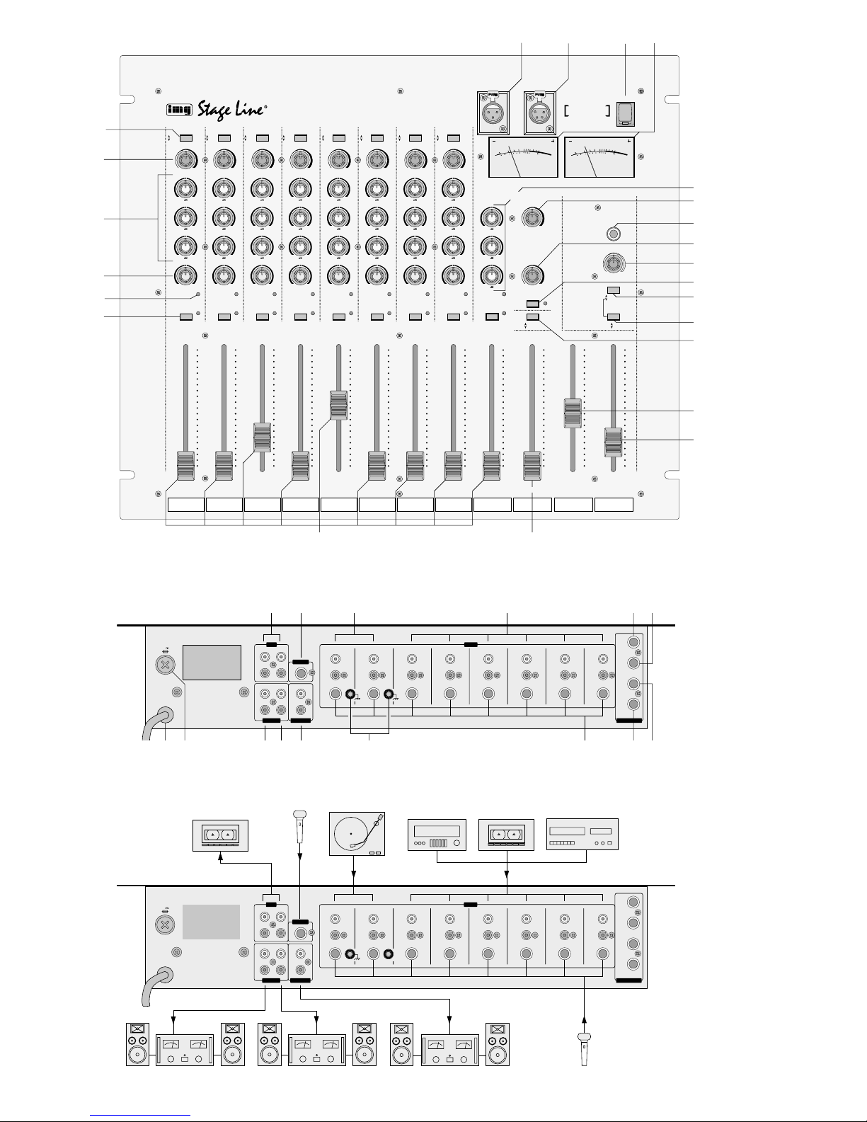
Bitte klappen Sie die Seite 3 heraus. Sie sehen
dann immer die beschriebenen Bedienelemente
und Anschlüsse.
1 Übersicht der Bedienelemente und
Anschlüsse
1.1 Frontseite
1 XLR-Eingangsbuchse für den Anschluss eines
DJ-Mono-Mikrofons an den Kanal DJ MIC
2 XLR-Buchse LAMP zum Anschluss einer Pult-
leuchte (12V/max. 5W)
3 Ein-/Ausschalter POWER
4 VU-Meter
5 Umschalttasten für die Eingänge der Kanäle 1
-
8;
Tasten nicht gedrückt: Mono-Mikrofon (MIC)
Tasten gedrückt: Stereo-Line (LINE bzw.
CD) für die Kanäle 1–6
Stereo-Phono (PH.) für
die Kanäle 7 und 8
6 Regler GAIN zum Einstellen der Eingangsver-
stärkung für die Kanäle 1
-
8 und den Kanal DJ
MIC
7 3fache Klangregelung (Equalizer) für die Kanäle
1
-
8 und den Kanal DJ MIC
8 Balance-Regler BALfür die Eingangskanäle 1
-
8
9 Übersteuerungsanzeigen PEAK
Bei Übersteuerung eines Eingangskanals leuchtet die entsprechende LED auf.
10 Tasten PFL zum Abhören des jeweiligen Ein-
gangskanals über einen Kopfhörer bzw. über
eine Monitoranlage; bei gedrückter Taste leuchtet zur Anzeige der Vorhörfunktion die entsprechende LED neben der Taste auf.
11 Schieberegler (Fader) für die Stereo-Eingangs-
kanäle 1
-
8 und den Mono-Eingangskanal DJ
MIC
12 Schieberegler (Fader) für den Stereo-Monitor-
kanal
13 6,3-mm-Klinkenbuchse zum Anschluss eines
Stereo-Kopfhörers (Impedanz ≥ 8Ω)
14 Regler TALK zum Einstellen der Pegelabsen-
kung (0
-
20dB) der Eingangskanäle 1
-
8 bei
eingeschalteter T alkover-Funktion
Die stärkste Absenkung (20dB) liegt bei Position
„0“ des Reglers vor; je weiter der Regler aufgedreht wird, desto schwächer wird die Pegelabsenkung.
15 Lautstärkeregler LEVEL für den an Buchse (13)
angeschlossenen Kopfhörer
16 Taste TALKOVER für Mikrofon-Durchsagen über
das an Buchse (1) bzw. Buchse (23) angeschlossene DJ-Mikrofon
Bei gedrückter Taste werden die Pegel der übrigen Eingangskanäle um den mit dem Regler
(14) eingestellten Wert (0
-
20dB) abgesenkt; die
LED neben der Taste leuchtet zur Anzeige der
Talkover-Funktion auf.
17 Umschalttaste für den Kopfhörerausgang und
das VU-Meter
Bei nicht gedrückter Taste lässt sich der mit der
Taste PFL (10) angewählte Eingangskanal per
Kopfhörer abhören; das VU-Meter (4) zeigt den
Pegel des jeweiligen Kanals an.
Bei gedrückter Taste kann der mit der Taste (18)
angewählte Summenkanal abgehört werden;
das VU-Meter zeigt den Ausgangspegel des
jeweiligen Summenkanals an.
18 Taste zum Umschalten zwischen den Stereo-
Summenkanälen
Ist die Taste nicht gedrückt, ist der Summenkanal MASTER B angewählt; das VU-Meter (4)
zeigt den Ausgangspegel dieses Kanals an.
Bei gedrückter Taste ist der Summenkanal
MASTER A angewählt; das VU-Meter zeigt den
Ausgangspegel dieses Kanals an.
19 Umschalttaste für den Monitorausgang
Bei nicht gedrückter Taste stehen am Monitorausgang die Signale des mit der Taste PFL (10)
angewählten Eingangskanals zur Verfügung; der
Ausgangspegel des Vorhörsignals ist unabhän-
gig von der Stellung des jeweiligen Kanalfaders
(Pre Fader).
Bei gedrückter Taste liegt am Monitorausgang je
nach Position der Taste (18) der Summenkanal
MASTER Aoder MASTER B an; der Ausgangspegel der Stereosumme ist von der Stellung des
entsprechenden Summenreglers (20 bzw. 21)
abhängig (Post Fader).
20 Schieberegler (Fader) für den Stereo-Summen-
kanal MASTER A
21 Schieberegler (Fader) für den Stereo-Summen-
kanal MASTER B
1.2 Rückseite
22 Cinch-Ausgangsbuchsen REC für den An-
schluss von Tonaufnahmegeräten; der Aufnahmepegel ist unabhängig von der Stellung der
Summenregler (20 + 21)
23 6,3-mm-Klinken-Eingangsbuchse DJ MIC für
den Anschluss eines DJ-Mono-Mikrofons an den
Kanal DJ MIC
24 Cinch-Eingangsbuchsen PHONO für Kanal 7 und
8 zum Anschluss von Plattenspielern mit Magnetsystem
25 Cinch-Eingangsbuchsen LINE bzw. CD für die
Kanäle 1
-
6 zum Anschluss von Geräten mit
Line-Pegel (z.B Tuner, CD-Spieler, Kassettenrecorder)
26 6,3-mm-Klinkenbuchse für den Faderstart des
Gerätes an Kanal 5
27 6,3-mm-Klinkenbuchse für den Faderstart des
Gerätes an Kanal 6
28 Netzkabel zum Anschluss an 230V~/ 50 Hz
29 Netzsicherung; eine durchgebrannte Sicherung
nur durch eine gleichen Typs ersetzen
30 Cinch-Summenausgang MASTER B für den
Anschluss eines Verstärkers
31 Cinch-Summenausgang MASTER A für den
Anschluss eines Verstärkers
Please unfold page 3. Then you can always see the
operating elements and connections described.
1 Operating Elements and Connections
1.1 Front panel
1 XLR input jack for connecting a DJ mono micro-
phone to the channel DJ MIC
2 XLR jack LAMP for connecting a gooseneck
lamp (12V/max. 5W)
3 On/off switch POWER
4 VU meters
5 Selector buttons for the inputs of channels 1
-
8;
Buttons not pressed: mono microphone (MIC)
Buttons pressed: stereo line (LINE resp.
CD) for channels 1
-
6
stereo phono (PH.) for
channels 7 and 8
6 GAIN controls for adjusting the input amplifica-
tion of channels 1
-
8 and the channel DJ MIC
7 3-way equalizers for the channels 1
-
8 and the
channel DJ MIC
8 Balance controls BALfor the input channels 1
-
8
9 Overload indicators PEAK
The corresponding LED lights during an overload of an input channel.
10 PFL buttons for monitoring the corresponding
input channel via headphones resp. via a monitor
system; if the button is pressed the corresponding LED next to the button lights to indicate the
monitoring function.
11 Slide controls (faders) for the stereo input chan-
nels 1
-
8 and the mono input channel DJ MIC
12 Slide control (fader) for the stereo monitor
channel
13 6.3mm jack for connecting stereo headphones
(impedance ≥ 8Ω)
14 TALK control for adjusting the level attenuation
(0
-
20dB) of the input channels 1-8 during acti-
vated talkover function
The strongest attenuation (20 dB) is at the “0”
position of the control; the more the control is
turned up, the less the level attenuation.
15 Volume control LEVEL for the headphones con-
nected to jack (13)
16 TALKOVER button for microphone announce-
ments via the DJ microphone connected to the
jack (1) resp. jack (23)
If the button is pressed, the levels of the other
input channels are attenuated by the value
(0–20 dB) adjusted with the control (14); the corresponding LED next to the button lights to indicate the talkover function.
17 Selector button for the headphones output and
the VU meters
If the button is not pressed, the input channel selected with the PFL button (10) can be monitored
via headphones; the VU meters show the level of
the corresponding channel.
If the button is pressed, the master channel selected with the button (18) can be monitored; the
VU meters show the output level of the corresponding master channel.
18 Button for switching between the stereo master
channels
If the button is not pressed, the master channel
MASTER B is selected; the VU meters (4) show
the output level of this channel.
If the button is pressed, the master channel
MASTER Ais selected; the VU meters show the
output level of this channel.
19 Selector button for the monitor output
If the button is not pressed, the signals of the
input channel selected with the PFL button (10)
are available at the monitor output; the output
level of the pre-fader signal is independent from
the position of the corresponding channel fader
(pre fader).
If the button is pressed, the master channel
MASTER A resp. MASTER B is available at the
monitor output according to the setting of the
button (18); the output level of the stereo master
depends upon the setting of the corresponding
master control (20 resp. 21) (post fader).
20 Slide control (fader) for the stereo master chan-
nel MASTER A
21 Slide control (fader) for the stereo master chan-
nel MASTER B
1.1 Rear panel
22 Phono output jacks REC for the connection of
sound recording units; the recording level is independent from the setting of the master controls (20 + 21)
23 6.3 mm input jack DJ MIC for connecting a DJ
mono microphone to the DJ MIC channel
24 Phono input jacks PHONO for channels 7 and 8
for connecting turntables with magnet system
25 Phono input jacks LINE resp. CD for channels
1
-
6 for connecting units with line level (e. g.
tuner, CD player, tape recorder)
26 6.3mm jack for the fader start of the unit at chan-
nel 5
27 6.3mm jack for the fader start of the unit at
channel 6
28 Mains cable for connecting to 230V~/50Hz
29 Mains fuse; replace a burnt-out fuse by one of
the same type only
30 Phono master output MASTER B for connecting
an amplifier
31 Phono master output MASTER A for connecting
an amplifier
32 Phono monitor output MONITOR for connecting
a monitor system
33 Connection for common ground, e. g. with turn-
tables
34 6.3mm input jacks MIC for channels 1
-
8 for
connecting mono microphones
35 6.3mm jack for the fader start of the unit at chan-
nel 8
36 6.3mm jack for the fader start of the unit at chan-
nel 7
4
GB
D
A
CH

32 Cinch-Monitorausgang MONITOR für den An-
schluss einer Monitoranlage
33 Anschluss für gemeinsamen Massepunkt, z.B
für Plattenspieler
34 6,3-mm-Klinken-Eingangsbuchsen MIC für die
Kanäle 1
-
8 zum Anschluss von Mono-Mikrofo-
nen
35 6,3-mm-Klinkenbuchse für den Faderstart des
Gerätes an Kanal 8
36 6,3-mm-Klinkenbuchse für den Faderstart des
Gerätes an Kanal 7
2 Hinweise für den sicheren Gebrauch
Dieses Gerät entspricht der Richtlinie für elektromagnetische Verträglichkeit 89/336/EWG und der Niederspannungsrichtlinie 73/23/EWG.
Beachten Sie unbedingt die folgenden Punkte:
●
Das Gerät ist nur zur Verwendung in Innenräumen
geeignet. Schützen Sie es vor Tropf- und Spritzwasser, hoher Luftfeuchtigkeit und Hitze (zulässiger Einsatztemperaturbereich 0–40 °C).
●
Stellen Sie keine mit Flüssigkeit gefüllten Gefäße,
z.B. Trinkgläser, auf das Gerät.
●
Nehmen Sie das Gerät nicht in Betrieb bzw. ziehen
Sie sofort den Netzstecker aus der Steckdose:
1. wenn sichtbare Schäden am Gerät oder an der
Netzanschlussleitung vorhanden sind,
2. wenn nach einem Sturz oder Ähnlichem der
Verdacht auf einen Defekt besteht,
3. wenn Funktionsstörungen auftreten.
Lassen Sie das Gerät in jedem Fall in einer Fachwerkstatt reparieren.
●
Ziehen Sie den Netzstecker nie an der Zuleitung
aus der Steckdose, fassen Sie immer am Stecker
an.
●
Eine beschädigte Netzanschlussleitung darf nur
durch den Hersteller oder durch eine autorisierte
Fachwerkstatt ersetzt werden.
●
Verwenden Sie für die Reinigung nur ein trockenes, weiches Tuch, niemals Wasser oder Chemikalien.
●
Wird das Gerät zweckentfremdet, falsch bedient
oder nicht fachgerecht repariert, kann für eventuelle Schäden keine Haftung übernommen werden.
●
Soll das Gerät endgültig aus dem Betrieb genommen werden, übergeben Sie es zur umweltgerechten Entsorgung einem örtlichen Recyclingbetrieb.
3 Einsatzmöglichkeiten
Das Stereo-Mischpult MMX-834 lässt sich sowohl
frei aufstellen als auch in ein 19"-Rack einbauen.
Für den Rackeinbau wird eine Höhe von 9HE
(Höheneinheiten) benötigt. Das Mischpult ist speziell für Musiker und den Einsatz auf der Bühne ausgelegt. Acht Stereo-Kanäle und ein Mono-DJ-Mikrofonkanal lassen sich auf zwei getrennte StereoSummenkanäle sowie auf einen Stereo-Monitorkanal mischen.
4 Inbetriebnahme
1) Die Tonquellen an die entsprechenden Eingangsbuchsen auf der Rückseite des Mischpultes anschließen:
Buchsen LINE bzw. CD (25) für den Anschluss
von Geräten mit Line-Pegel (z.B Tuner, CD-Spieler, Kassettenrecorder);
Buchsen PHONO (24) für den Anschluss von
Plattenspielern mit Magnetsystem;
Buchsen MIC (34) für den Anschluss von MonoMikrofonen.
Ein DJ-Mono-Mikrofon kann an die XLR-Buchse
DJ MIC (1) auf der Frontseite des Gerätes oder
an die 6,3-mm-Klinkenbuchse DJ MIC (23) auf
der Geräterückseite angeschlossen werden. Die
XLR-Buchse besitzt eine Verriegelung, die beim
Herausziehen des Mikrofon-Steckers durch Herunterdrücken des PUSH-Hebels wieder gelöst
wird.
2) Die Umschalttaste (5) für die Kanäle 1
-
8 entsprechend betätigen: Bei nicht gedrückter Taste
ist der Mono-Mikrofon-Eingang des jeweiligen
Kanals angewählt, bei gedrückter Taste der Stereo-Line-Eingang (Kanäle 1
-
6) bzw. der Stereo-
Phono-Eingang (Kanäle 7 und 8).
3) Den bzw. die Verstärker an die Ausgangsbuchsen MASTER B (30) und/ oder MASTER A (31)
anschließen.
4) Die Monitoranlage an die Ausgangsbuchsen (32)
anschließen.
5) Für eventuelle Tonaufnahmen ein oder zwei Aufnahmegeräte an die Ausgangsbuchsen REC (22)
anschließen. Der Aufnahmepegel ist unabhängig
von der Stellung der beiden Summenregler (20
und 21).
Wichtig! Bei Aufnahmen nicht die TALKOVER-
Taste (16) drücken, da in diesem Fall
bei Mikrofondurchsagen über das DJMikrofon die Ausgangspegel der RECAusgänge um den mit dem Regler
TALK (14) eingestellten Wert abgesenkt werden.
6) Für eine optimale Pultbeleuchtung kann an die
Buchse LAMP(2) eine Schwanenhals-Pultleuchte
12V/ max. 5W (z. B. MONACOR GNL-405, nicht
im Lieferumfang) angeschlossen werden, die mit
dem Mischpult ein- und ausgeschaltet wird.
7) Den Netzstecker in die Steckdose (230V~/
50Hz) stecken.
Achtung! Das Gerät wird mit lebensgefährlicher
Netzspannung (230 V~) versorgt. Nehmen Sie deshalb niemals selbst Eingriffe im Gerät vor. Durch unsachgemäßes Vorgehen besteht die Gefahr
eines elektrischen Schlages. Außerdem
erlischt beim Öffnen des Gerätes jeglicher Garantieanspruch.
2 Safety Notes
This unit corresponds to the directive for electromagnetic compatibility 89/ 336 /EEC and to the low
voltage directive 73/23/EEC.
Please observe the following items in any case:
●
The unit is suitable for indoor use only. Protect it
against dripping water and splash water, high air
humidity, and heat (admissible ambient temperature range 0–40 °C).
●
Do not place any vessel filled with liquid on the
unit, e.g. a drinking glass.
●
Do not operate the unit or immediately disconnect
the plug from the mains socket
1. if there is visible damage to the unit or to the
mains cable,
2. if a defect might have occurred after the unit
was dropped or suffered a similar accident,
3. if malfunctions occur.
In any case the unit must be repaired by skilled
personnel.
●
Never pull the mains cable for disconnecting the
mains plug from the socket.
●
A damaged mains cable must be replaced by the
manufacturer or skilled personnel only.
●
For cleaning only use a dry, soft cloth, by no
means chemicals or water.
●
No liability for any damage will be accepted if the
unit is used for other purposes than originally
intended, if it is not correctly operated or not repaired in an expert way.
●
If the unit is to be put out of operation definitively,
take it to a local recycling plant for a disposal
which is not harmful to the environment.
●
Important for U.K. Customers!
The wires in this mains lead are coloured in accordance with the following code:
blue = neutral
brown = live
As the colours of the wires in the mains lead of this
appliance may not correspond with the coloured
markings identifying the terminals in your plug,
proceed as follows:
1. The wire which is coloured blue must be
connected to the terminal in the plug which is
marked with the letter N or coloured black.
2. The wire which is coloured brown must be
connected to the terminal which is marked with
the letter L or coloured red.
3 Installation
The stereo mixer MMX-834 may be used as a table
top unit or may be installed in a 19" rack. Aheight of
9 HE (rack spaces) is required for rack installation.
The mixer is especially designed for musicians and
stage applications. Eight stereo channels and a
mono DJ microphone channel can be mixed to two
separate stereo master channels as well as to a
stereo monitor channel.
4 Setting Into Operation
1) Connect the sound sources to the corresponding
input jacks at the rear panel of the mixer:
LINE resp. CD jacks (25) for connecting units with
line level (e.g. tuner, CD player, tape recorder);
PHONO jacks (24) for connecting turntables with
magnet system;
MIC jacks (34) for connecting mono microphones.
A DJ mono microphone can be connected to the
XLR jack DJ MIC (1) at the front panel of the unit
or to the 6.3 mm jack DJ MIC (23) at the rear
panel of the unit. The XLR jack is equipped with a
lock which is released by pressing the PUSH
lever down and pulling the microphone plug out
at the same time.
2) Press the selector button (5) for channels 1
-
8
accordingly: if the button is not pressed, the
mono microphone input of the corresponding
channel is selected, if the button is pressed, the
stereo line input (channels 1
-
6) resp. the stereo
phono input (channels 7 and 8) is selected.
3) Connect one or two amplifiers to the output jacks
MASTER B (30) and/or MASTER A(31).
4) Connect the monitor system to the output jacks
(32).
5) Connect one or two recording units to the output
jacks REC (22) if sound recordings are required.
The recording level is independent from the setting of both master controls (20 and 21).
Important! Do not press the TALKOVER button
(16) during sound recordings as
otherwise the output levels of the
REC outputs will be decreased during microphone announcements via
the DJ microphone by the value
adjusted with the TALK control (14).
6) A gooseneck console lamp 12V/ max. 5 W (e. g.
MONACOR GNL-405, not included) may be connected to the LAMP jack (2) for an optimum console lighting; the lamp is switched on and off with
the mixer.
7) Plug the mains plug into the mains socket
(230V~/50 Hz).
8) Before switching on the mixer, set the master
controls (20) and (21) and the monitor control
(12) to minimum so that strong inrush bump is
avoided. Afterwards, switch on the mixer with the
on/off switch (3).
9) Switch on the connected units.
Attention! The unit is supplied with hazardous
mains voltage (230 V~). Leave servicing to skilled personnel only. Inexpert
handling may cause an electric shock
hazard. Furthermore, any guarantee
claim will expire if the unit has been
opened.
5
GB
D
A
CH

8) Vor dem Einschalten des Mischpultes sollten die
Summenregler (20) und (21) und der Monitorregler (12) auf Minimum gestellt werden, um starke
Einschaltgeräusche zu vermeiden. Dann das
Mischpult mit dem Ein-/Ausschalter (3) einschalten.
9) Die angeschlossenen Geräte einschalten.
5 Bedienung
5.1 Mischen der angeschlossenen Tonquellen
Vor der ersten Inbetriebnahme alle GAIN-Regler (6)
und Klangregler (7) auf Mittelposition stellen.
1) Mit den Summenreglern (20) und (21) lässt sich
die Gesamtlautstärke der angeschlossenen Tonquellen einstellen. Der mit dem Summenregler
MASTER A (20) eingestellte Ausgangspegel
steht am Summenausgang MASTER A (31) zur
Verfügung, der mit dem Summenregler MASTER
B (21) eingestellte Ausgangspegel wird dem
Summenausgang MASTER B (30) zugeführt. Zur
Pegeleinstellung der angeschlossenen Geräte
die Summenregler auf ca.
2
/3 des Maximums
stellen, z.B. auf Position 7.
2) Das VU-Meter (4) zeigt bei gedrückter Umschalttaste (17) den Pegel der Signalsumme an: bei
nicht gedrückter Taste (18) den Ausgangspegel
des Summenkanals MASTER B, bei gedrückter
Taste (18) den Ausgangspegel des Summenkanals MASTER A.
3) Mit den Fadern (11) die Pegel der Eingangskanäle einstellen. Die Fader sollten nach der
Pegeleinstellung auf ca.
2
/3 des Maximums stehen, damit beim Ein- und Ausblenden genügend
Reglerweg vorhanden ist. Bei wenig oder sehr
weit aufgezogenen Fadern müssen die Pegel
durch Verstellen der GAIN-Regler (6) entsprechend angepasst werden.
Übersteuerungen werden für jeden Kanal
durch Aufleuchten der entsprechenden LED
PEAK (9) angezeigt.
4) Mit der Klangregelung (7) das Klangbild der
Kanäle 1
-
8 und des Kanals DJ MIC einstellen.
Durch Verstellen der drei Regler lassen sich die
Tiefen, Höhen und Mitten eines Kanals bis zu
12dB anheben bzw. absenken. Befinden sich die
Regler in der Mittelstellung, findet keine Frequenzgangbeeinflussung statt.
5) Mit den Balance-Reglern BAL (8) für die StereoEingangskanäle 1
-
8 die Balance einstellen. Bei
Mono-Signalen auf diesen Kanälen arbeiten die
Balance-Regler wie Panorama-Regler.
5.2 Vorhören der Kanäle
Jede am Mischpult angeschlossene Tonquelle kann
einzeln über einen Kopfhörer oder eine Monitoranlage abgehört werden, auch wenn der dazugehörige
Fader (11) auf Minimum steht (PFL = Pre Fader
Listening). Die Vorhörfunktion ermöglicht das optimale Einstellen der GAIN-Regler bei der Pegelanpassung. Außerdem kann durch das Abhören eines
Eingangskanals der günstigste Zeitpunkt zum Einblenden der entsprechenden Tonquelle gewählt
werden.
Es ist ebenfalls möglich, die Stereo-Summensig-
nale über den angeschlossenen Kopfhörer oder die
Monitoranlage abzuhören. Dabei ist der Ausgangspegel der Stereosumme abhängig von der Stellung
des mit der Taste (18) angewählten Summenreglers
(Post Fader).
5.2.1 Vorhören über den Kopfhörer
1) Einen Kopfhörer (≥ 8 Ω) an die Buchse (13) anschließen.
2) Zum Abhören eines Eingangskanals die Taste
PFL (10) des entsprechenden Kanals drücken.
Zur Anzeige der Vorhörfunktion leuchtet die entsprechende LED neben der Taste auf.
3) Soll ein Eingangskanal abgehört werden, darf die
Umschalttaste (17) nicht gedrückt sein. Das VUMeter (4) zeigt dann den Signalpegel des mit der
Taste PFL (10) angewählten Kanals.
Zum Abhören eines Summenkanals die Umschalttaste (17) drücken. Das VU-Meter zeigt
dann den Ausgangspegel des mit der Taste (18)
angewählten Summenkanals an.
4) Mit dem Regler LEVEL (15) die gewünschte
Kopfhörer-Lautstärke einstellen.
5.2.2 Vorhören über die Monitoranlage
1) Die Monitoranlage an die Buchsen MONITOR
(32) anschließen.
2) Zum Abhören eines Eingangskanals die Taste
PFL (10) des entsprechenden Kanals drücken.
Zur Anzeige der Vorhörfunktion leuchtet die entsprechende LED neben der Taste auf.
3) Soll ein Eingangskanal abgehört werden, darf die
Umschalttaste (19) nicht gedrückt sein. Die Vorhörsignale der mit der Taste PFL (10) angewählten Eingangskanäle stehen dann am Monitorausgang zur Verfügung.
Soll ein Stereo-Summensignal dem Monitorausgang zugeführt werden, die Umschalttaste
(19) drücken. Mit der Taste (18) den gewünschten Summenkanal anwählen.
4) Mit dem Monitorfader (12) den Pegel für das zur
Monitoranlage abgehende Signal einstellen.
5.3 Durchsagen über das DJ-Mikrofon
Ist die Taste TALKOVER (16) gedrückt, werden bei
Mikrofondurchsagen über das DJ-Mikrofon an
Buchse (1) bzw. an Buchse (23) die Pegel der übrigen Eingangskanäle abgesenkt. Die LED neben der
Vorsicht! Stellen Sie die Lautstärke der Audio-
anlage und die Kopfhörerlautstärke nie
sehr hoch ein. Hohe Lautstärken können auf Dauer das Gehör schädigen!
Das menschliche Ohr gewöhnt sich an
große Lautstärken und empfindet sie
nach einiger Zeit als nicht mehr so
hoch. Darum eine hohe Lautstärke nach
der Gewöhnung nicht weiter erhöhen.
5 Operation
5.1 Mixing of the connected sound sources
Before switching on for the first time, set all GAIN
controls (6) and equalizers (7) to center position.
1) The total volume of the connected sound sources
can be adjusted with the master controls (20) and
(21). The output level adjusted with the master
control MASTER A(20) is available at the master
output MASTER A(31), the output level adjusted
with the master control MASTER B (21) is fed to
the master output MASTER B (30). For the level
adjustment of the connected units set the master
controls to approx.
2
/3 of the maximum, e.g. posi-
tion 7.
2) The VU meters (4) show the level of the signal
sum if the selector button (17) is pressed: the output level of the master channel MASTER B if the
button (18) is not pressed, the output level of the
master channel MASTER A if the button (18) is
pressed.
3) Adjust the levels of the input channels with the
faders (11). The faders should be set to approx.
2
/3 of the maximum after the level adjustment so
that there is sufficient control range for fading in
and out. If the faders are almost at minimum or
maximum, the levels have to be adjusted correspondingly with the GAIN controls (6).
Overloads are indicated for each channel via
lighting of the corresponding PEAK LED (9).
4) Adjust the sound characteristics of the channels
1
-
8 and the DJ MIC channel with the tone con-
trols (7). By turning the three controls, the low,
medium, and high frequencies of a channel can
be increased resp. decreased up to 12 dB. The
frequency is not influenced if the controls are in
center position.
5) Adjust the balance for the stereo input channels
1
-
8 with the balance controls BAL (8). The
balance controls function as panorama controls if
mono signals are fed to these channels.
5.2 Monitoring of the channels
Each sound source connected to the mixer can be
monitored separately via headphones or a monitor
system, even if the corresponding fader (11) is at
minimum (pre fader). The PFL function (PFL = pre
fader listening) enables the optimum setting of the
GAIN controls during the level matching. Furthermore, the best timing for fading in the corresponding
sound source can be chosen via monitoring of an
input channel.
It is also possible to monitor the stereo master
signals via the connected headphones or the monitor system. The output level of the stereo master
depends upon the position of the master control
(post fader) selected with the button (18).
5.2.1 Monitoring via headphones
1) Connect headphones (≥ 8 Ω) to the jack (13).
2) For monitoring an input channel, press the PFL
button (10) of the corresponding channel. The
corresponding LED next to the button lights to
indicate the monitoring function.
3) The selector button (17) must not be pressed if
an input channel is going to be monitored. The
VU meters (4) will then show the signal level of
the channel selected with the PFL button (10).
Press the selector button (17) to monitor a
master channel. The VU meters will then show
the output level of the master channel selected
with the button (18).
4) Adjust the desired headphones volume with the
LEVEL control (15).
5.2.2 Monitoring via the monitor system
1) Connect the monitor system to the MONITOR
jacks (32).
2) For monitoring of an input channel press the PFL
button (10) of the corresponding channel. The
corresponding LED next to the button lights to
indicate the monitoring function.
3) The selector button (19) must not be pressed if
an input channel is going to be monitored. The
pre-fader signals of the input channels selected
with the PFL button (10) are available at the
monitor output.
Press the selector button (19) if a stereo
master signal is to be fed to the monitor output.
Select the desired master channel with the button
(18).
4) Use the monitor fader (12) to adjust the level of
the signal which is fed to the monitor system.
5.3 Announcements via the DJ microphone
If the TALKOVER button (16) is pressed, the levels
of the other input channels are decreased during
microphone announcements via the DJ microphone
at jack (1) resp. jack (23). The corresponding LED
next to the button lights to indicate the talkover function. Adjust the desired level attenuation (0dB up to
20 dB) with the TALK control (14). The strongest
attenuation (20dB) is at the “0” position of the control; the more the control is turned up, the less the
level attenuation.
5.4 Fader start of turntables and CD players
CD players resp. turntables at channels 5–8 can be
started remotely via the mixer. The corresponding
control input of the connected unit must be connected to one of the 6.3mm jacks FADERSTART at the
rear panel of the mixer (see fig. 4):
Unit at channel 5: Connect to jack CH 5 (26),
Unit at channel 6: Connect to jack CH 6 (27),
Unit at channel 7: Connect to jack CH 7 (36),
Unit at channel 8: Connect to jack CH 8 (35).
Caution! Do not adjust the audio system or the
headphones to a very high volume. Permanent high volumes may damage
your hearing! The human ear will get
accustomed to high volumes which do
not seem to be that high after some
time. Therefore, do not further increase
a high volume after getting used to it.
6
GB
D
A
CH
Taste leuchtet zur Anzeige der Talkover-Funktion
auf. Mit dem Regler TALK (14) die gewünschte
Pegelabsenkung (0dB bis 20dB) einstellen. Die
stärkste Absenkung (20dB) liegt bei Position „0“ des
Reglers vor; je weiter der Regler aufgedreht wird,
desto schwächer wird die Pegelabsenkung.
5.4 Faderstart von Plattenspielern und CDSpielern
CD-Spieler bzw. Plattenspieler an den Kanälen 5-8
können über das Mischpult ferngestartet werden.
Dazu muss der entsprechende Steuereingang des
angeschlossenen Gerätes mit einer der 6,3-mmKlinkenbuchsen FADERSTART auf der Rückseite
des Mischpultes verbunden werden (siehe Abb. 4):
Gerät an Kanal 5: Anschluss an Buchse CH 5 (26),
Gerät an Kanal 6: Anschluss an Buchse CH 6 (27),
Gerät an Kanal 7: Anschluss an Buchse CH 7 (36),
Gerät an Kanal 8: Anschluss an Buchse CH 8 (35).
Beim Aufziehen des jeweiligen Faders (11) wird ein
Schalter geschlossen und startet dadurch den CDSpieler bzw. Plattenspieler. Wird der Fader wieder
auf Minimum gestellt, öffnet der Schalter und das
angeschlossene Gerät stoppt.
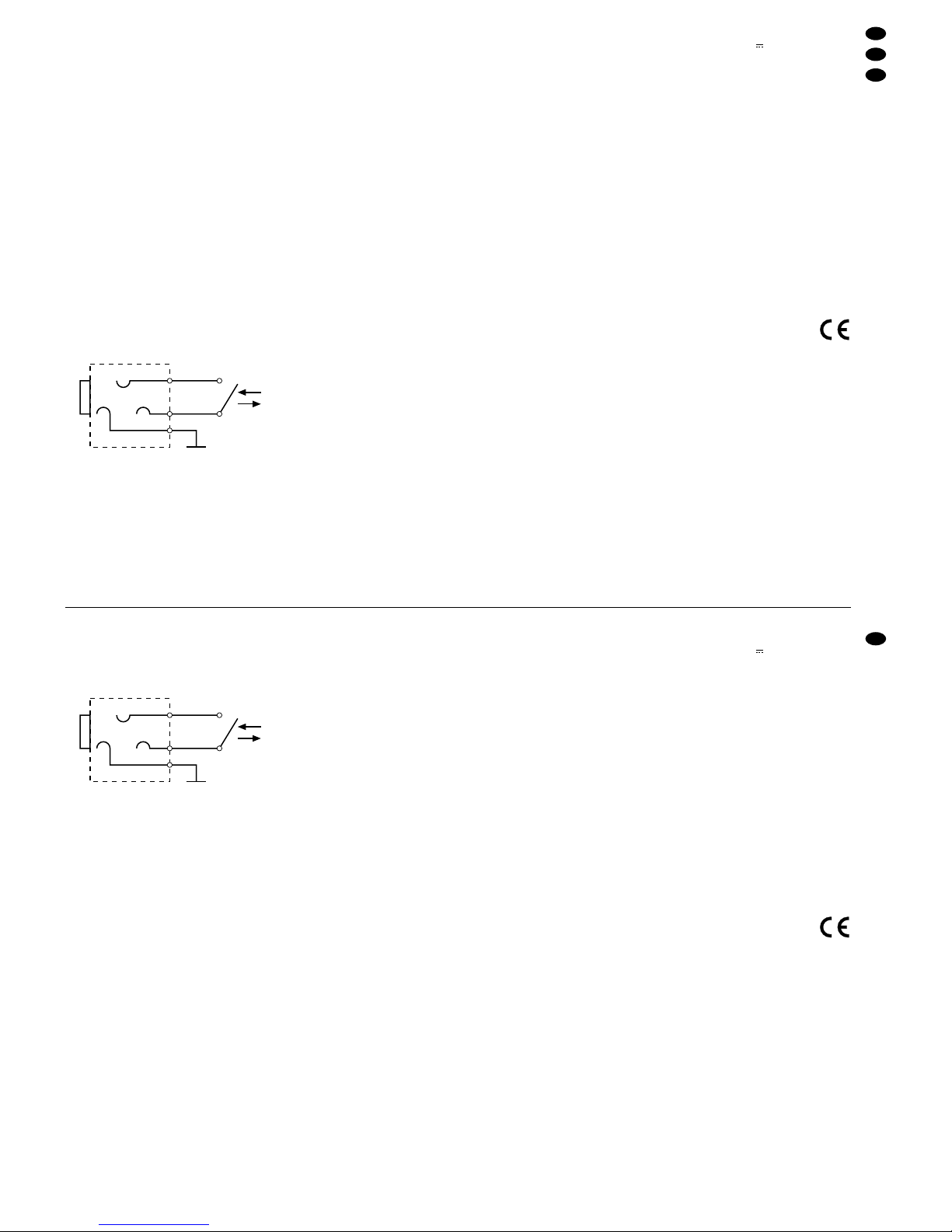
6,3-mm-Klinkenbuchse für den Faderstart
➃
Wird ein Mono-Klinkenstecker in die Buchsen
FADERSTART gesteckt, liegt ein Kontakt des
Faderstart-Schalters an Masse. Sollte in diesem Fall
der Faderstart nicht funktionieren, muss ein StereoKlinkenstecker verwendet werden.
6 Technische Daten
Eingänge
8 x Mono-Mic: . . . . . . . 3 mV/600 Ω
1 x Mono-DJ-Mic: . . . . 3mV/600Ω
6 x Stereo-Line: . . . . . . 150mV/100kΩ
2 x Stereo-Phono: . . . . 3mV/50 kΩ (RIAA)
Ausgänge
2 x Stereo-Summe: . . . 1V/600 Ω, 8V max.
1 x Stereo-Monitor: . . . 1 V/600 Ω, 8 V max.
2 x Stereo-Record: . . . 0,775V/600Ω, 4V max.
Frequenzbereich: . . . . . . . 20
-
20000 Hz,
±0,5dB (RIAA ±2dB)
Klirrfaktor: . . . . . . . . . . . . < 0,1%
Störabstand
Line: . . . . . . . . . . . . . . . 70dB
Mic: . . . . . . . . . . . . . . . 55 dB
Phono: . . . . . . . . . . . . . 55dB
Klangregler
9 x Tiefen: . . . . . . . . . . ±12dB/100Hz
9 x Mitten: . . . . . . . . . . ±12dB/1kHz
9 x Höhen: . . . . . . . . . . ±12 dB/10kHz
Talkover: . . . . . . . . . . . . . 0
-
20dB, einstellbar
Kopfhörerausgang: . . . . . 0,5W/≥ 8 Ω, Stereo
Max. Kontaktbelastung
für Faderstart: . . . . . . . . . 24V /500mA
Anschluss für Pultleuchte: 12 V/max. 5 W
Stromversorgung: . . . . . . 230V~/50Hz/25 VA
Einsatztemperatur: . . . . . 0 –40°C
Abmessungen (BxH x T): 482 x 127 x 402 mm,
9HE
Gewicht: . . . . . . . . . . . . . . 7,8 kg
Anschlüsse
DJ-Mic: . . . . . . . . . . . . 1 x XLR, symm.,
1 x 6,3-mm-Klinke,
symm.
Mic: . . . . . . . . . . . . . . . 8 x 6,3-mm-Klinke,
symm.
Faderstart: . . . . . . . . . . 4 x 6,3-mm-Klinke
Kopfhörer: . . . . . . . . . . 1 x 6,3-mm-Klinke
Pultleuchte: . . . . . . . . . 1 x XLR, 4-polig
Alle anderen
Audioanschlüsse . . . . . 26 x Cinch
Laut Angaben des Herstellers.
Änderungen vorbehalten.
Start
Stop
By opening the corresponding fader (11) a switch
is closed and the CD player resp. the turntable is
started. If the fader is moved back to minimum, the
switch opens and the connected unit stops.
6.3mm jack for the fader start
➃
If a mono plug is inserted into the FADERSTART
jacks, one contact of the fader start switch is connected to ground. If the fader start does not function
in this case, a stereo plug has to be used.
6 Specifications
Inputs
8 x Mono mic: . . . . . . . 3mV/600 Ω
1 x Mono DJ mic: . . . . . 3mV/600Ω
6 x Stereo line: . . . . . . . 150mV/100 kΩ
2 x Stereo phono: . . . . 3mV/50 kΩ (RIAA)
Outputs
2 x Stereo master: . . . . 1V/600Ω, 8V max.
1 x Stereo monitor: . . . 1V/600 Ω, 8V max.
2 x Stereo record: . . . . 0.775 V/600 Ω, 4 V max.
Frequency range: . . . . . . 20 –20000 Hz,
±0.5dB (RIAA ±2dB)
THD: . . . . . . . . . . . . . . . . < 0.1%
S/N ratio
Line: . . . . . . . . . . . . . . . 70dB
Mic: . . . . . . . . . . . . . . . 55 dB
Phono: . . . . . . . . . . . . . 55dB
Tone controls
9 x Bass: . . . . . . . . . . . ± 12dB/100 Hz
9 x Midrange: . . . . . . . . ± 12dB/1 kHz
9 x Treble: . . . . . . . . . . ±12 dB/10kHz
Talkover: . . . . . . . . . . . . . 0
-
20dB, adjustable
Headphones output: . . . . 0.5W/≥ 8 Ω, stereo
Max. contact rating
for fader start: . . . . . . . . . 24V /500 mA
Connection for
gooseneck lamp: . . . . . . . 12 V/max. 5 W
Power supply: . . . . . . . . . 230V~/50Hz/25 VA
Ambient temperature: . . . 0–40°C
Dimensions (W x H x D): . 482 x 127 x 402mm,
9HE (rack spaces)
Weight: . . . . . . . . . . . . . . . 7.8 kg
Connections
DJ mic: . . . . . . . . . . . . . 1 x XLR, balanced
1 x 6.3mm jack,
balanced
Mic: . . . . . . . . . . . . . . . 8 x 6.3 mm jack,
balanced
Fader start: . . . . . . . . . 4 x 6.3mm jack
Headphones: . . . . . . . . 1 x 6.3mm jack
Gooseneck lamp: . . . . . 1 x XLR, 4-pole
All other audio
connections: . . . . . . . . 26 x phono
According to the manufacturer.
Subject to technical change.
Start
Stop
7
GB
D
A
CH

Ouvrez le présent livret page 3 de manière à
visualiser les éléments et branchements.
1 Eléments et branchements
1.1 Face avant
1 Prise d’entrée XLR : branchement d’un micro
mono DJ sur le canal DJ MIC
2 Prise XLR LAMP : branchement d’une lampe
pupitre 12V/max. 5W
3 Interrupteur Marche/Arrêt POWER
4 VU-mètres
5 Sélecteurs pour les entrées des canaux 1–8 :
touches non enfoncées :micro mono (MIC)
touches enfoncées : stéréo Line (LINE/CD)
pour les canaux 1–6
stéréo Phono (PH.)
pour les canaux 7–8
6 Potentiomètres rotatifs GAIN : réglage de l’am-
plification d’entrée des canaux 1– 8 et du canal
DJ MIC
7 Egaliseur 3 voies pour les canaux 1–8 et le
canal DJ MIC
8 Potentiomètres rotatifs de réglage de balance
pour les niveaux d’entrée 1–8
9 Diode PEAK : témoin d’écrêtage
En cas de surcharge d’un canal d’entrée, la
diode correspondante s’allume.
10 Touches PFL : préécoute d’un canal d’entrée via
un casque ou un système Monitor
Si la touche est enfoncée, la diode correspondante s’allume pour indiquer la fonction préécoute.
11 Potentiomètres à glissières pour les canaux d’en-
trée stéréo 1–8 et le canal d’entrée mono DJ MIC
12 Potentiomètre à glissière pour le canal monitor
stéréo
13 Prise jack 6,35 : branchement d’un casque stéréo
(impédance ≥8Ω)
14 Potentiomètre TALK : réglage de l’atténuation de
niveau (0–20 dB) des canaux d’entrée 1– 8 lorsque la fonction TALKOVER est activée
En position “0”, l’atténuation est la plus importante (20dB) ; plus le potentiomètre est poussé,
plus elle est faible.
15 Potentiomètre de réglage de volume LEVEL du
casque relié à la prise (13)
16 Touche TALKOVER pour des annonces micro
via le micro relié à la prise (1) ou (23)
Si la touche est enfoncée, les niveaux des autres
canaux d’entrée sont diminués de la valeur
réglée avec le potentiomètre (14) de 0 à 20dB ;
la diode à côté de la touche s’allume.
17 Sélecteur pour la sortie casque et le VU-mètre
Si la touche n’est pas enfoncée, vous pouvez
faire une préécoute du canal d’entrée sélectionné avec la touche PFL (10), le VU-mètre (4)
indique le niveau du canal sélectionné.
Si elle est enfoncée, vous pouvez faire une préécoute du canal Master sélectionné avec la touche (18), le VU-mètre indique le niveau de sortie
du canal Master sélectionné.
18 Sélecteur entre les canaux Master stéréo
Si la touche n’est pas enfoncée, le canal Master
MASTER B est sélectionné, le VU-mètre (4) indique le niveau de sortie de ce canal.
Si elle est enfoncée, le canal Master MASTER A
est sélectionné, le VU-mètre indique alors le
niveau de sortie de ce canal.
19 Sélecteur pour la sortie Moniteur
Si elle n’est pas enfoncée, les signaux du canal
d’entrée sélectionné avec la touche PFL (10) est
sur la sortie Moniteur. Le niveau de sortie du signal de préécoute est indépendant de la position
du potentiomètre de ce canal (Pre fader).
Si la touche est enfoncée, le canal Master
MASTER A/MASTER B est disponible sur la sortie Moniteur en fonction de la position du sélecteur (18). Le niveau de sortie du Master stéréo
dépend de la positon du potentiomètre Master
correspondant (20/21) (Post fader).
20 Potentiomètre à glissières (fader) : canal Master
stéréo MASTER A
21 Potentiomètre à glissières (fader) : canal Master
stéréo MASTER B
1.2 Face arrière
22 Prises RCA REC : branchement de magnéto-
phones: le niveau de sortie est indépendant de la
position des potentiomètres Master (20+21).
23 Prise d’entrée jack 6,35 DJ MIC : branchement
d’un micro mono DJ sur le canal DJ MIC
24 Prises d’entrée RCA PHONO pour le canal 7 et
le canal 8 : branchement de platine-disques à
système magnétique
25 Prises d’entrée RCA LINE/ CD pour les canaux
1– 6 : branchement d’appareils à niveau Line
(p.ex., tuner, lecteur CD, magnétophones)
26 Prise jack 6,35 pour le démarrage électrique de
l’appareil sur le canal 5
27 Prise jack 6,35 pour le démarrage électrique de
l’appareil sur le canal 6
28 Cordon secteur, 230 V~/50 Hz
29 Fusible ; tout fusible endommagé doit être rem-
placé uniquement par un fusible de même type
30 Sortie Master RCA MASTER B : branchement
d’un amplificateur
31 Sortie Master RCA MASTER A : branchement
d’un amplificateur
32 Sortie Moniteur RCA MONITOR : branchement
d’un système Moniteur
33 Branchement pour une masse commune, p. ex.
pour une platine-disques.
34 Prises d’entrée jack 6,35 MIC pour les canaux
1–8 : branchement de micros mono
35 Prise jack 6,35 : démarrage électrique de l’ap-
pareil sur le canal 8
36 Prise jack 6,35 : démarrage électrique de l’ap-
pareil sur le canal 7
Vi consigliamo di aprire completamente la
pagina 3. Così vedrete sempre gli elementi di
comando e i collegamenti descritti.
1 Gli elementi di comando e i
collegamenti
1.1 Pannello frontale
1 Presa XLR per il collegamento del microfono DJ
mono con il canale DJ MIC
2 Presa XLR LAMPper il collegamento di una lam-
pada (12V/max. 5W)
3 Interruttore On/Off POWER
4 VU-metro
5 Tasti di commutazione per gli ingressi dei canali
1–8;
tasti non premuti: microfono mono (MIC)
tasti premuti: stereo-Line (LINE o CD) per
i canali 1–6
stereo-Phono (PH.) per i canali 7 e 8
6 Regolatori GAIN per regolare l’amplificazione
d’ingresso per i canali 1–8 e per il canale DJ MIC
7 Regolatore toni con 3 diverse frequenze (equa-
lizzatore) per i canali 1–8 e per il canale DJ MIC
8 Regolazione bilanciamento BALper i canali d’in-
gresso 1–8
9 Led di sovrapilotaggio PEAK
Nel caso di sovrapilotaggio di un canale d’ingresso il relativo led si accende.
10 Tasti PFL per ascoltare il relativo canale d’in-
gresso mediante una cuffia o un monitor; con il
tasto PFL premuto, come controllo del preascolto si accende il led vicino al tasto.
11 Cursori (fader) per i canali d'ingresso stereo 1–8
e per il canale mono DJ MIC
12 Cursore (fader) per il canale stereo monitor
13 Presa jack 6,3mm per il collegamento di una cuf-
fia (impedenza ≥ 8Ω)
14 Regolatore TALK per impostare l’abbassamento
del livello (0 – 20 dB) dei canali d’ingresso 1– 8
con la funzione talkover inserita
L’abbassamento più forte (20 dB) si ha in posizione “0”; più si apre il regolatore, più si riduce
l’abbassamento del livello.
15 Regolatore LEVEL per la cuffia collegata alla
presa (13)
16 Tasto TALKOVER per avvisi fatti dal microfono
DJ collegato alle prese (1) o (23)
Con il tasto premuto, i livelli degli altri canali d’ingresso vengono abbassati del valore (0–20dB)
impostato con il regolatore (14). Un led vicino al
tasto segnala che la funzione di talkover è attiva.
17 Tasto di commutazione per l’uscita cuffia e per il
VU-metro
Con il tasto non premuto, è possibile ascoltare
con la cuffia il canale d’ingresso selezionato con
il tasto PFL (10); il VU-metro (4) visualizza il
livello del relativo canale.
Con il tasto premuto, è possibile ascoltare il
canale delle somme selezionato con il tasto (18);
il VU-metro visualizza il livello del relativo canale.
18 Tasto di commutazione fra i canali stereo delle
somme
Col tasto non premuto è selezionato il canale
delle somme MASTER B; il VU-metro (4) indica il
livello d’uscita di quel canale.
Col tasto premuto è selezionato il canale delle
somme MASTER A; il VU-metro indica il livello
d’uscita di quel canale.
19 Tasto di commutazione per l’uscita monitor
Con il tasto non premuto, l’uscita monitor riceve i
segnali del canale d’ingresso selezionato con il
tasto PFL (10). Il livello d’uscita del segnale di
preascolto è indipendente dalla posizione del
relativo fader (prefader).
Con il tasto premuto, a seconda della posizione
del tasto (18), l’uscita monitor riceve i segnali dei
canali MASTER Ao MASTER B. Il livello d’uscita
della somma stereo dipende dalla posizione del
relativo regolatore (20 o 21) (postfader).
20 Cursore (fader) per il canale stereo delle somme
MASTER A
21 Cursore (fader) per il canale stereo delle somme
MASTER B
1.2 Pannello posteriore
22 Prese d'uscita cinch REC per il collegamento di
registratori; il livello di registrazione è indipendente dalla posizione dei due regolatori delle
somme (20 + 21)
23 Prese jack 6,3mm DJ MIC per il collegamento di
un microfono mono al canale DJ MIC
24 Prese cinch d’ingresso PHONO dei canali 7 e 8
per il collegamento di giradischi con sistema
magnetico
25 Prese cinch d'ingresso CD o LINE dei canali 1–6
per collegare apparecchi con livello Line (p. es.
tuner, lettore CD, registratore a cassette)
26 Presa jack 6,3 mm per l’avviamento con fader
attraverso il canale 5
27 Presa jack 6,3 mm per l’avviamento con fader
attraverso il canale 6
28 Cavo rete 230V~/50Hz
29 Fusibile di rete; sostituire un fusibile bruciato
solo con uno dello stesso tipo
30 Uscita cinch delle somme MASTER B per il col-
legamento di un amplificatore
31 Uscita cinch delle somme MASTER A per il col-
legamento di un amplificatore
32 Uscita cinch MONITOR per il collegamento di un
impianto monitor
33 Contatto comune di massa, p. es. per un giradi-
schi
34 Prese d’ingresso jack 6,3mm MIC dei canali 1–8
per il collegamento di microfoni mono.
35 Presa jack 6,3 mm per l’avviamento con fader
attraverso il canale 8
36 Presa jack 6,3 mm per l’avviamento con fader
attraverso il canale 7
8
I
F
B
CH
 Loading...