

Audio-Mischpult
mit Effektprozessor
Audio Mixer
with Effect Processor
MMX-82UFX
Bestell-Nr. • Order No. 20.2830
BEDIENUNGSANLEITUNG
INSTRUCTION MANUAL
MODE D’EMPLOI
ISTRUZIONI PER L’USO
GEBRUIKSAANWIJZING
MANUAL DE INSTRUCCIONES
INSTRUKCJA OBSŁUGI
SIKKERHEDSOPLYSNINGER
SÄKERHETSFÖRESKRIFTER
TURVALLISUUDESTA
ELECTRONICS FOR SPECIALISTS ELECTRONICS FOR SPECIALISTS ELECTRONICS FOR SPECIALISTS ELECTRONICS FOR SPECIALISTS

Deutsch ...........Seite 4
English ............Page 10
Français ...........Page 16
Italiano............Pagina 22
Nederlands ........Pagina 28
Español ...........Página 34
Polski .............Strona 40
Dansk .............Sida 46
Svenska ...........Sidan 46
Suomi.............Sivulta 47
ELECTRONICS FOR SPECIALISTS ELECTRONICS FOR SPECIALISTS ELECTRONICS FOR SPECIALISTS ELECTRONICS FOR SPECIALISTS
2
22 23
MIC
BAL/ UNBAL
IN OUTTAPE
L
R
21
LINE
20
MIN MAX
GAIN
CH1
0
17
–15 +15
600
15
100
0
13
–15 +15
0
12
–15 +15
0
11
0
9
C
7
L R
MUTE
10
5
0dB
-5
-10
-20
-30
-40
-50
-60
1 1
CH1
18 19
75Hz
EQ
HIGH
12kHz
MID
FREQ
8kHz
MID
LOW
80Hz
AUX
SEND
1
MON
+15
10
PFL
2
FX
+15
PAN
6
5
PEAK
4
1-2
3
L-R
2
SOLO
➀ ➁ ➂
21
17
16
14
12
11
L
MONO
BAL/
LINE
UNBAL
R
+4
–10
CH9 /10
0
EQ
HIGH
12kHz
–15 +15
0
MID
3kHz
–15 +15
0
MID
500Hz
–15 +15
0
LOW
80Hz
–15 +15
0
AUX
SEND
1
MON
+15
0
9
C
8
L R
MUTE
10
5
0dB
-5
-10
-20
-30
-40
-50
-60
10
PFL
2
FX
+15
BAL
6
5
PEAK
4
1-2
3
L-R
2
SOLO
CH9 /10
33
32
31
30
29
28
27
26
25
24
MMX-82U FX
00-09 VOCAL
10-19 SMALL ROOM
20-29 LARGE HALL
30-39 ECHO
40-49 ECHO +VERB
50-59 FLANGE + VERB
60-69 PLATE
70-79 CHORUS +GTR
80-89 ROTARY +GTR
90-99 TREMOLO +GTR
BOOTH
MASTER
CD/ USB
MIX
TAPE
0
AUX SEND
MASTER
1
MON
+15
0
2
FX
+15
SUB ASSIGN TO MASTER
L R L R
MUTE MUTE
10
5 5 5 5
0dB
-5
-10
-20
-30
-40
-50
-60
EFFECT
DSP
24 BIT DIGITAL EF FECTS
PUSH
FX SELECT
0
SUB
MAX
BOOTH/
PHONES
AUX RTN
0
FX RETURN
0
10
0dB
-5
-10
-20
-30
-40
-50
-60
TAPE/USB
TO MIX
MASTER
SUB1-2
+15
RETURN
TO AUX1
0
+15
+15
PHANTOM
48V
10
0dB
-5
-10
-20
-30
-40
-50
-60
1-2
SOLO
SOLO
SUB 1 SUB 2 L MASTER R
PEAK
MUTE
PFL-GREEN
AFL-RED
POWER
CLIP
+10
+7
+4
+2
0dB
-2
-4
-7
-10
-20
-30
ON
45
44
43
42
41
40
39
38
37
36
35
10
0dB
-5
-10
-20
-30
-40
-50
-60
34
230V~
50Hz
MIC
MIC
MIC
MIC
MIC
BAL/UNBAL
BAL/UNBAL
BAL/UNBAL
BAL/UNBAL
LINE
LINE
LINE
LINE
MIN MAX
MIN MAX
MIN MAX
GAIN
75Hz
CH1 CH2 CH3 CH4 CH5 CH6 CH7 CH8 CH9/ 10 C H11 /12
0
EQ
HIGH
12kHz
–15 +15
–15 +15
600
MID
FREQ
100
8kHz
100
0
MID
–15 +15
–15 +15
0
LOW
80Hz
–15 +15
–15 +15
0
AUX
SEND
1
MON
+15
0
PFL
2
FX
+15
C
PAN
L R
L R
MUTE
MUTE
PEAK
10
5 5 5 5 5 5 5 5 5 5 5 5 5 5
0dB
1-2
-5
-10
L-R
-20
-30
SOLO
-40
-50
-60
CH1 CH2 CH3 CH4 CH5 CH6 CH7 CH8
MIN MAX
GAIN
GAIN
GAIN
75Hz
75Hz
0
0
0
EQ
EQ
HIGH
HIGH
12kHz
12kHz
–15 +15
–15 +15
600
600
600
MID
MID
FREQ
FREQ
8kHz
8kHz
100
8kHz
100
0
0
0
MID
MID
–15 +15
–15 +15
0
0
0
LOW
LOW
80Hz
80Hz
–15 +15
–15 +15
0
0
0
AUX
AUX
SEND
SEND
1
1
MON
MON
+15
+15
0
+15
C
10
0dB
-5
-10
-20
-30
-40
-50
-60
+15
0
0
PFL
PFL
2
2
FX
FX
+15
+15
C
C
PAN
PAN
L R
L R
MUTE
MUTE
PEAK
PEAK
10
10
0dB
0dB
1-2
1-2
-5
-5
-10
-10
L-R
L-R
-20
-20
-30
-30
SOLO
SOLO
-40
-40
-50
-50
-60
-60
R L
POWER
PHANTOM
MIC
BAL/UNBAL
BAL/UNBAL
LINE
LINE
MIN MAX
MIN MAX
GAIN
GAIN
75Hz
75Hz
0
0
EQ
EQ
HIGH
HIGH
12kHz
12kHz
–15 +15
–15 +15
600
600
MID
MID
FREQ
FREQ
8kHz
100
8kHz
100
0
0
MID
MID
–15 +15
–15 +15
0
0
LOW
LOW
80Hz
80Hz
–15 +15
–15 +15
0
0
AUX
AUX
SEND
SEND
1
1
MON
MON
+15
+15
0
0
PFL
PFL
2
2
FX
FX
+15
+15
C
C
PAN
PAN
L R
L R
MUTE
MUTE
PEAK
PEAK
10
10
0dB
0dB
1-2
1-2
-5
-5
-10
-10
L-R
L-R
-20
-20
-30
-30
SOLO
SOLO
-40
-40
-50
-50
-60
-60
MASTER FOOT
BAL/ UNBAL
L
MIC
BAL/UNBAL
LINE
MIN MAX
GAIN
75Hz
0
EQ
HIGH
12kHz
–15 +15
600
MID
FREQ
8kHz
100
0
MID
–15 +15
0
LOW
80Hz
–15 +15
0
AUX
SEND
1
MON
+15
0
PFL
2
FX
+15
C
PAN
L R
MUTE
PEAK
10
0dB
1-2
-5
-10
L-R
-20
-30
SOLO
-40
-50
-60
SWITCH
PHONES
R
MIC
BAL/UNBAL
IN OUTTAPE
L
L
MONO
MONO
BAL/
LINE
BAL/
LINE
LINE
MIN MAX
GAIN
75Hz
75Hz
0
EQ
EQ
HIGH
HIGH
12kHz
12kHz
–15 +15
600
MID
MID
FREQ
FREQ
8kHz
100
0
MID
MID
–15 +15
0
LOW
LOW
80Hz
80Hz
–15 +15
0
AUX
AUX
SEND
SEND
1
1
MON
MON
+15
0
PFL
PFL
2
2
FX
FX
+15
C
PAN
PAN
L R
MUTE
PEAK
PEAK
10
0dB
1-2
1-2
-5
-10
L-R
L-R
-20
-30
SOLO
SOLO
-40
-50
-60
BOOTHOUT SUB OUT AUX SEND AUX RTN FX RTN CHANNEL INSERTS
L
R
+4
–10
0
–15 +15
0
–15 +15
0
–15 +15
0
–15 +15
0
+15
0
+15
C
L R
MUTE
10
0dB
-5
-10
-20
-30
-40
-50
-60
CH9/ 10
UNBAL
UNBAL
R
R
LINE
MMX-82UFX
OPT
00-09 VOCAL
EFFECT
10-19 SMALL ROOM
20-29 LARGE HALL
EQ
0
EQ
HIGH
HIGH
12kHz
12kHz
–15 +15
0
MID
MID
3kHz
3kHz
–15 +15
0
MID
MID
500Hz
500Hz
–15 +15
0
LOW
LOW
80Hz
80Hz
–15 +15
AUX
AUX
SEND
SEND
1
1
MON
MON
+150+15
PFL
PFL
2
2
FX
FX
+150+15
C
BAL
BAL
L R
MUTE MUTE MUTE
PEAK
PEAK
10
0dB
1-2
1-2
-5
-10
L-R
L-R
-20
-30
SOLO
SOLO
-40
-50
-60
CH11/ 12
SUB 1 SUB 2 L MASTER R
1
12LRLR7856341
30-39 ECHO
40-49 ECHO +VERB
50-59 FLANGE + VERB
60-69 PLATE
70-79 CHORUS +GTR
80-89 ROTARY +GTR
90-99 TREMOLO +GTR
BOOTH
MASTER
CD/USB
MIX
TAPE
0
AUX SEND
MASTER
1
MON
0
2
FX
SUB ASSIGN TO MASTER
L R L R
10
0dB
-5
-10
-20
-30
-40
-50
-60
DSP
24 BIT DIGITAL EFFECTS
PUSH
FX SELECT
0
SUB
MAX
TAPE/USB
1-2
BOOTH/
TO MIX
PHONES
MASTER
AUX RTN
SUB1-2
0
SOLO
+15
RETURN
TO AUX1
FX RETURN
0
SOLO
+150+15
48V
10
10
0dB
0dB
-5
-5
-10
-10
-20
-20
-30
-30
-40
-40
-50
-50
-60
-60
2
PEAK
MUTE
PFL-GREEN
AFL-RED
CLIP
+10
+7
+4
+2
0dB
-2
-4
-7
-10
-20
-30
POWERONPHANTOM
10
0dB
-5
-10
-20
-30
-40
-50
-60
➃
2
FUSE
➄
46 47 48 49 50 51 52 53 54 55 56 57 58
3

Audio-Mischpult
Diese Anleitung richtet sich an Benutzer mit
Grundkenntnissen in der Audiotechnik. Bitte
lesen Sie die Anleitung vor dem Betrieb gründ-
Deutsch
lich durch und heben Sie sie für ein späteres
Nachlesen auf.
Auf der ausklappbaren Seite 3 finden Sie
alle beschriebenen Bedienelemente und Anschlüsse.
Inhalt
1 Übersicht . . . . . . . . . . . . . . . . . 4
1.1 Eingangskanäle . . . . . . . . . . . . 4
1.2 Ausgangsfeld . . . . . . . . . . . . . 4
1.3 Rückseite . . . . . . . . . . . . . . . 5
2 Hinweise für den
sicherenGebrauch. . . . . . . . . . . .5
3 Einsatzmöglichkeiten . . . . . . . . . .5
4 Geräte anschließen . . . . . . . . . . . 6
4.1 Tonquellen. . . . . . . . . . . . . . . 6
4.1.1 Mikrofone . . . . . . . . . . . . . . 6
4.1.2 Line-Tonquellen . . . . . . . . . . . . 6
4.2 Effektgeräte . . . . . . . . . . . . . . 6
4.2.1 Effektgeräte einschleifen . . . . . . . 6
4.2.2 Ausspielwege verwenden . . . . . . . 6
4.3 Aufnahmegerät . . . . . . . . . . . . 6
4.4 Regie-Monitoranlage und
Kopfhörer anschließen. . . . . . . . . 6
4.5 Monitoranlage für die Musiker . . . . 6
4.6 Verstärker für die Saalbeschallung . . .6
4.7 Betrieb mit einem Computer . . . . . 6
4.8 Ausgänge der Subgruppen . . . . . . 7
4.9 Fußtaster für den Effektprozessor . . . 7
4.10 Stromversorgung . . . . . . . . . . . 7
5 Bedienung. . . . . . . . . . . . . . . . .7
5.1 Ein- und Ausschalten . . . . . . . . . 7
5.2 Aussteuerung der Eingangskanäle . . .7
5.3 Eingangssignale mischen . . . . . . . 7
5.4 Monitor-Ausspielweg einstellen . . . . 8
5.5 Effekte zumischen . . . . . . . . . . .8
5.5.1 Verwendung des internen
Effektprozessors . . . . . . . . . . . 8
5.5.2 Externes Effektgerät . . . . . . . . . 8
5.5.3 Separates Effektgerät
fürdieSubgruppen . . . . . . . . . . 9
5.6 Abhören über einen Kopfhörer
und eine Regie-Monitoranlage. . . . . 9
6 Technische Daten . . . . . . . . . . . . 9
6.1 Steckerbelegung XLR und Klinke . . . 9
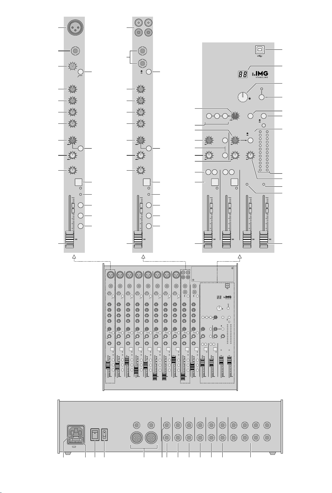
1 Übersicht
1.1 Eingangskanäle
Abb. 1 Mono-Eingangskanal CH 1; die weiteren
Mono-Eingangskanäle sind identisch.
Abb. 2 Stereo-Eingangskanal CH 9 / 10; der
zweite Stereo-Eingangskanal ist bis auf die Taste
mit der Position 19 identisch.
1
Kanalfader für die Kanallautstärke und zum
Ein- und Ausblenden des Kanalsignals
2
Taste SOLO zum Abhören des gewählten
Kanals über einen an der Buchse PHONES
(52) angeschlossenen Kopfhörer und über
eine an den Buchsen BOOTH OUT (53) angeschlossene Monitoranlage:
entweder zum Vorhören, wenn die Taste
PFL /AFL (40) ausgerastet ist
oder zur Kontrolle der gesamten Kanaleinstellung nach dem Kanalfader, wenn die
Taste PFL /AFL hineingedrückt ist
Bei hineingedrückter Taste SOLO leuchtet
die zugehörige LED PEAK (5) ständig und
die Aussteuerungsanzeige (38) zeigt das
zugehörige Kanalsignal an.
3
Taste L-R: Bei hineingedrückter Taste wird
das Kanalsignal auf die Summenkanäle
MASTER gemischt. Mit dem Regler PAN (7)
oder BAL (8) kann das Signal nur auf den
rechten oder linken Kanal gemischt werden
oder auf beide Kanäle.
4
Taste 1-2: Bei hineingedrückter Taste wird
das Kanalsignal auf die Subgruppen SUB 1
und SUB 2 gemischt. Mit dem Regler PAN
(7) oder BAL (8) kann das Signal nur auf die
Gruppe SUB 1 oder SUB 2 gemischt werden
oder auf beide Gruppen.
5 LED PEAK: Ist die Taste SOLO (2) hineinge-
drückt, leuchtet sie ständig. Ist die Taste
SOLO ausgerastet, zeigt ein kurzes Aufleuchten an, dass der maximale unverzerrte
Signalpegel erreicht ist. Leuchtet sie länger,
wird der Kanal übersteuert. Dann den Regler
GAIN (20) entsprechend zudrehen.
6 Taste MUTE mit Kontroll-LED zum Stumm-
schalten des Kanals
7
Panoramaregler PAN zum Platzieren des
Mono-Signals im Stereo-Klangbild
Wenn die Taste 1-2 (4) hineingedrückt ist,
dient der Regler zum Zuweisen des Kanalsignals auf die Subgruppen.
8 Balanceregler
Wenn die Taste 1-2 (4) hineingedrückt ist,
dient der Regler zum Zuweisen des Kanalsignals auf die Subgruppen.
9 Regler AUX SEND 2 / FX zum Mischen des
Kanalsignals auf den Ausspielweg 2 (postfader); dieser Ausspielweg dient gleichzeitig
als Effektweg für den internen Effektprozessor
10 Umschalttaste PRE für den Ausspielweg 1
ausgerastet: Signalabgriff post-fader
Das Kanalsignal wird nach dem Fader (1)
auf den Ausspielweg gegeben.
hineingedrückt: Signalabgriff pre-fader
Das Kanalsignal wird vor dem Fader auf
den Ausspielweg gegeben.
11
Regler AUX SEND 1 / MON zum Mischen des
Kanalsignals auf den Ausspielweg 1
12 Klangregler LOW 80 Hz für die Bässe:
±15 dB bei 80 Hz
13 Klangregler MID für die Mitten:
±15 dB bei 100 Hz – 8 kHz
14 Klangregler MID 500 Hz für die Mitten bei
500 Hz: ±15 dB
15
Regler MID FREQ zum Einstellen der Filterfrequenz (100 Hz – 8 kHz) für die Klangregelung
im Mittenbereich
16
Klangregler MID 3 kHz für die Mitten bei
3 kHz: ±15 dB
17 Klangregler HIGH 12 kHz für die Höhen:
±15 dB bei 12 kHz
18
Taste für das Low-Cut-Filter (Hochpass)
Bei hineingedrückter Taste werden unerwünschte Signalanteile unter 75 Hz unterdrückt, z. B. Trittschall.
19 Kanal CH 9 / 10:
Taste +4 /−10 zur Pegelanpassung für Geräte
mit niedrigem Ausgangspegel; bei hineingedrückter Taste wird der Eingangspegel
angehoben
Kanal CH 11 / 12:
Taste LINE /OPT zum Umschalten des Kanaleingangs
ausgerastet: Eingang = Buchsen LINE (21)
hineingedrückt: Eingang = Signal von
einem Zusatzmodul (z. B. MP3-Spieler),
das anstelle der Blende oben rechts eingesetzt ist
20
Regler GAIN zum Einstellen der Eingangsverstärkung
21
Eingang LINE (6,3-mm-Klinke, sym.) für
den Anschluss einer Signalquelle mit LineAusgangspegel (z. B. Musikinstrument,
CD/ MP3-Spieler)
Hinweis für die Stereo-Kanäle: Beim An-
schluss eines Mono-Geräts nur die Buchse L
verwenden. Das Signal wird dann intern auf
den rechten und linken Kanal geleitet.
22 Eingang MIC für den Anschluss eines Mik-
rofons (XLR-Buchse, sym.)
Für alle Mikrofoneingänge lässt sich die
Phantomspeisung zuschalten,
tion49.
23
Ein- und Ausgangsbuchsen (Cinch) TAPE für
ein Aufnahmegerät
An den Buchsen OUT liegt das Summensignal an [nach den Fadern MASTER (34)].
Das Signal der Buchsen IN wird bei hineingedrückter Taste TAPE / USB TO MIX (41) vor
den Fadern MASTER auf das Summensignal
gemischt.
☞
Posi-
1.2 Ausgangsfeld
24 Fader für die Subgruppen 1 und 2
25
Tasten MUTE mit Kontroll-LED zum Stummschalten der Subgruppen
26
Zuordnungstasten SUB ASSIGN TO MASTER
zum Weiterleiten der Subgruppensignale auf
den linken oder / und rechten Summenkanal
27 Pegelregler FX RETURN für das Effektsignal
des internen Effektprozessors oder das Signal am Eingang FX RETURN (57)
Das Signal wird mit dem Regler auf die Summenkanäle MASTER gemischt.
28 Pegelregler AUX SEND MASTER 2 / FX für
das Gesamtsignal des Ausspielwegs2, das
auf den internen Effektprozessor und auf
den Ausgang AUX SEND 2 (55) gegeben
wird
29 Taste SOLO – jeweils für den Ausspielweg1
und 2 – zum Abhören des Ausspielwegs
über einen an der Buchse PHONES (52) angeschlossenen Kopfhörer und über eine an
4
den Buchsen BOOTH OUT (53) angeschlossene Monitoranlage
30
Pegelregler AUX SEND MASTER 1 / MON
für das Gesamtsignal des Ausspielwegs1,
das am Ausgang AUX SEND 1 (55) zur Verfügung steht
31
Pegelregler AUX RTN, um die Signale am
Eingang AUX RTN (56) auf die Summenkanäle MASTER zu mischen [Taste MASTER /
SUB 1-2 (39) ausgerastet] oder auf die Subgruppenkanäle [Taste hineingedrückt]
32 Tasten BOOTH zur Auswahl der Signale, die
über den Kopfhörerausgang PHONES (52)
und den Ausgang BOOTH OUT (53) abgehört und von der Aussteuerungsanzeige (38)
angezeigt werden sollen:
– Taste MASTER MIX für Ausgangssignale
der Summenkanäle MASTER
– Taste CD / USB / TAPE für die Eingangssig
nale der Buchsen TAPE IN (23) und der
USB-Buchse (45)
– Taste SUB 1-2 für Signale der Subgruppen
1 und 2
Hinweise:
1. Sind mehrere Tasten hineingedrückt, wird das
Mischsignal der zugehörigen Quellen abgehört und angezeigt.
2. Die mit den Tasten SOLO (2, 29) gewählten
Abhörsignale haben Vorrang: Ist eine Taste
SOLO hineingedrückt, werden die zugehörigen Signale abgehört und angezeigt und nicht
die mit den Tasten BOOTH gewählten Signale.
33
Lautstärkeregler BOOTH / PHONES für den
Kopfhörerausgang PHONES (52) und den
Ausgang BOOTH OUT (53)
34 Fader für die Summenkanäle
35
Kontrollanzeige PHANTOM 48 V: leuchtet
bei eingeschalteter Phantomspeisung für die
Eingänge MIC (22)
36 Betriebsanzeige POWER ON
37 Regler RETURN TO AUX 1 zum Mischen der
Signale des internen Effektprozessors oder
der Signale der Buchsen FX RTN (57) auf den
Ausspielweg 1
38
Aussteuerungsanzeige; zeigt den Pegel
des Signals an, das zum Abhören über den
Kopfhörerausgang PHONES (52) und den
Ausgang BOOTH OUT (53) gewählt ist:
– die Signale der Eingangskanäle /Ausspiel-
wege, bei denen die Taste SOLO (2, 29)
hineingedrückt ist
– wenn keine Taste SOLO hineingedrückt ist,
das mit der Taste BOOTH (32) ge wählte
Abhörsignal
39
Zuordnungstaste MASTER / SUB 1-2 zum
Weiterleiten der Signale des Eingangs AUX
RTN (56) auf die Summenkanäle MASTER
(Taste ausgerastet) oder auf die Subgruppenkanäle (Taste hineingedrückt)
40 Taste PFL /AFL mit Kontroll-LED darunter:
Taste ausgerastet = PFL (pre fader listening)
Die Eingangskanäle, bei denen die Taste
SOLO (2) hineingedrückt ist, werden vor
dem Regler PAN (7) bzw. BAL (8) und dem
Fader (1) abgehört und die Ausspielwege,
bei denen die Taste SOLO (29) hineingedrückt ist, vor dem Regler AUX SEND
(28,30).
Taste hineingedrückt = AFL
(after fader listening)
Die Eingangskanäle, bei denen die Taste
SOLO hineingedrückt ist, werden nach
dem Regler PAN bzw. BAL und dem
Fader abgehört und die Ausspielwege,
bei denen die Taste SOLO hineingedrückt
ist, nach dem Regler AUX SEND.
41
Taste TAPE / USB TO MIX: Bei hineingedrückter Taste werden die Eingangssignale der
Buchsen TAPE IN (23) und der USB-Buchse
(45) auf die Summenkanäle MASTER geleitet.
42
Taste MUTE zum Ein- und Ausschalten eines
gewählten Effektes
Die LED PEAK über der Taste leuchtet kontinuierlich, wenn der Effekt ausgeschaltet ist.
Bei eingeschaltetem Effekt leuchtet sie nur
bei Übersteuerung des Effektprozessors auf.
43
Knopf FX SELECT zur Effektauswahl: Den
Knopf drehen, bis im Display (44) die Effektnummer blinkend angezeigt wird, dann zur
Bestätigung den Knopf kurz drücken.
44 Display EFFECT zur Anzeige der gewählten
Effektnummer
45
USB-Buchse (Typ B) zur Verbindung
mit einem Computer; kann gleichzeitig als
Ausgang (digitale Ausgabe des Summensignals) und als Eingang (Einspeisen von Audiodaten) genutzt werden (Voll-Duplex-Betrieb)
1.3 Rückseite
46 Netzbuchse zum Anschluss an eine Steck-
dose (230 V/ 50 Hz) über das beiliegende
Netzkabel
47 Halterung für die Netzsicherung
Eine geschmolzene Sicherung nur durch eine
gleichen Typs ersetzen.
48 Ein- /Ausschalter POWER
49
Ein- /Ausschalter PHANTOM der 48-V-Phantomspeisung für alle Mikrofoneingänge MIC
(22); bei eingeschalteter Phantomspeisung
leuchtet die LED PHANTOM 48 V (35)
Beachten Sie bitte die Vorsichtshinweise zur
Phantomspeisung in Kapitel 4.1.1
50 Ausgänge MASTER für das Summensignal,
z. B. zum Anschluss des Verstärkers für die
Saalbeschallung
– über XLR-Buchsen,
Links L / Rechts R, symmetrisch
– über 6,3-mm-Klinkenbuchsen,
Links L / Rechts R, asymmetrisch
51 Anschluss FOOT SWITCH (6,3-mm-Klinken-
buchse, 2-polig) für einen Fußtaster zum
Ein- /Ausschalten des internen Effektprozessors
52 Ausgang PHONES (6,3-mm-Klinkenbuchse)
für den Anschluss eines Stereo-Kopfhörers
(Impedanz min. 8 Ω)
53
Ausgang BOOTH OUT (6,3-mm-Klinkenbuchsen Links L / Rechts R, asym.) für den
Anschluss einer Regie-Monitoranlage
54 Ausgänge SUB OUT (6,3-mm-Klinkenbuch-
sen, asym.) für die Subgruppen 1 und 2
55
Ausgänge AUX SEND (6,3-mm-Klinkenbuchsen, asym.) für die Ausspielwege 1 und 2
56 Eingänge AUX RTN (6,3-mm-Klinkenbuch-
sen Links L / Rechts R, asym.), kann als Eingang für ein Effektgerät oder für eine zusätzliche Line-Tonquelle verwendet werden
Hinweis: Bei Anschluss eines Mono-Geräts nur
die Buchse L verwenden. Das Signal wird dann
intern auf den rechten und linken Kanal geleitet.
57
Effektsignaleingänge FX RTN (6,3-mm-Klinkenbuchsen Links L / Rechts R, asym.)
Beim Anschluss wird das Eingangssignal auf
die Summenkanäle geleitet und der Signal-
weg vom internen Effektprozessor zu den
Summenkanälen unterbrochen.
58 Buchsen CHANNEL INSERTS (6,3-mm-Klin-
kenbuchsen) zum Einschleifen von Effektgeräten (z. B. Kompressoren) in die Mono-Eingangskanäle CH 1 bis CH 8
Steckeranschlüsse:
Spitze = Send (Ausgang)
Ring = Return (Eingang)
Schaft = Masse
2 Hinweise für den
sicherenGebrauch
Das Gerät entspricht allen relevanten Richtlinien
der EU und trägt deshalb das -Zeichen.
WARNUNG
Verwenden Sie das Gerät nur im Innenbereich
•
und schützen Sie es vor Tropf- und Spritzwasser, hoher Luftfeuchtigkeit und Hitze (zulässiger Einsatztemperaturbereich 0 – 40 °C).
Stellen Sie keine mit Flüssigkeit gefüllten Ge-
•
fäße z. B. Trinkgläser, auf das Gerät.
Nehmen Sie das Gerät nicht in Betrieb und
•
ziehen Sie sofort den Netzstecker aus der
Steckdose,
1.
wenn sichtbare Schäden am Gerät oder am
Netzkabel vorhanden sind,
2.
wenn nach einem Sturz oder Ähnlichem der
Verdacht auf einen Defekt besteht,
3. wenn Funktionsstörungen auftreten.
Geben Sie das Gerät in jedem Fall zur Reparatur in eine Fachwerkstatt.
Ziehen Sie den Netzstecker nie am Kabel aus
•
der Steckdose, fassen Sie immer am Stecker an.
Verwenden Sie für die Reinigung nur ein tro-
•
ckenes, weiches Tuch, niemals Wasser oder
Chemikalien.
Wird das Gerät zweckentfremdet, nicht rich-
•
tig angeschlossen, falsch bedient oder nicht
fachgerecht repariert, kann keine Haftung für
daraus resultierende Sach- oder Personenschäden und keine Garantie für das Gerät
übernommen werden.
Das Gerät wird mit lebensgefährlicher Netzspannung versorgt.
Nehmen Sie deshalb niemals
selbst Eingriffe daran vor. Es
besteht die Gefahr eines elektrischen Schlages.
Soll das Gerät endgültig aus dem Betrieb genommen werden, übergeben
Sie es zur umweltgerechten Entsorgung
einem örtlichen Recyclingbetrieb.
3 Einsatzmöglichkeiten
Dieses Audio-Mischpult ist für diverse Beschallungs- und Aufnahmezwecke geeignet. Es verfügt über 8 Mono- und 2 Stereo-Eingangskanäle
zum Anschluss von Mikrofonen (auch phantomgespeiste) und Tonquellen mit Line-Ausgangspegel (z. B. Instrumente, Abspielgeräte).
Die Eingangssignale lassen sich auf einen Stereo-Summenkanal, zwei Subgruppen und auf
zwei Ausspielwege mischen. Zum Zumischen
von Effekten kann der integrierte Effektprozessor
verwendet werden. Die Tonmischung lässt sich
über einen Kopfhörer und /oder eine Monitoranlage in einem separaten Regieraum abhören.
Zusätzlich zu den Cinch-Anschlüssen für
ein Aufnahmegerät besitzt das Mischpult eine
USB-Audio-Schnittstelle zur Verbindung mit
Deutsch
5
einem Computer. Diese lässt sich sowohl als
RETURN SEND
Ausgang zur digitalen Aufnahme der Tonabmischung als auch als Eingang zum Einspeisen von
Audiodaten verwenden.
Deutsch
4 Geräte anschließen
Um Störgeräusche zu vermeiden, vor dem Herstellen / Trennen von Verbindungen das Mischpult
ausschalten oder folgende Regler / Fader ganz
zudrehen / zuziehen:
− MASTER (34)
− BOOTH / PHONES (33)
− AUX SEND MASTER 1 / MON (30), wenn der
Ausspielweg 1 als Monitorweg genutzt wird.
4.1 Tonquellen
Da in den Mono-Kanälen nicht zwischen den
Eingängen umgeschaltet werden kann, entweder den Mikrofoneingang (22) oder den Line-Eingang (21) anschließen, nie beide gleichzeitig.
4.1.1 Mikrofone
Mikrofone an die symmetrisch beschalteten
XLR-Buchsen MIC (22) anschließen. Für phantomgespeiste Mikrofone lässt sich mit dem
Schalter PHANTOM (49) auf der Rückseite für
alle XLR-Buchsen gemeinsam eine 48-V-Phantomspeisung einschalten. Bei aktivierter Phantomspeisung leuchtet die Anzeige PHANTOM
48 V (35).
Vorsicht: Bei eingeschalteter Phantomspeisung darf kein Mikrofon mit asymmetrischem
Ausgang angeschlossen sein, da dieses beschädigt werden kann.
Um Schaltgeräusche in den Lautsprechern und
im Kopfhörer zu vermeiden, die Phantomspeisung nur ein- oder ausschalten, wenn das
Mischpult ausgeschaltet ist oder die jeweiligen
Ausgangsregler ganz zurückgedreht sind.
4.1.2 Line-Tonquellen
Tonquellen mit Line-Signalpegel (z. B. Empfänger
von drahtlosen Mikrofonsystemen, Effektgeräte,
Instrumente, Abspielgeräte) an die 6,3-mm-Klinkenbuchsen LINE (21) der Eingangskanäle anschließen. Die Buchsen sind symmetrisch beschaltet. Es lassen sich aber auch Geräte mit
asymmetrisch beschaltetem Ausgang über zweipolige Klinkenstecker anschließen.
− Mono-Geräte an die Mono-Kanäle CH 1 bis
CH 8 anschließen.
− Stereo-Geräte an die Stereo-Kanäle CH 9 / 10
und CH 11 / 12 anschließen. Soll an einen
Stereo-Kanal ein Mono-Gerät angeschlossen
werden, nur die Buchse L verwenden. Das
Mono-Signal wird dann intern auf den rechten
und linken Kanal geleitet.
Reichen die Eingangskanäle nicht aus, können
zum Anschluss von zusätzlichen Line-Quellen
auch folgende Stereo-Eingänge genutzt werden:
1. der Eingang AUX RTN (56)
(Beim Anschluss eines Mono-Geräts nur die
Buchse L verwenden, das Mono-Signal wird
dann intern auf den linken und rechten Kanal
geleitet.)
2. der Eingang FX RTN (57)
(Beim Anschluss wird der Signalweg vom
internen Effektprozessor zu den Summenkanälen unterbrochen.)
3. der Eingang TAPE IN (23)
(z. B. zum Anschluss eines CD-Spielers für
Hintergrundmusik in den Spielpausen)
4.2 Effektgeräte
4.2.1 Effektgeräte einschleifen
Effektgeräte (z. B. Geräte zur Klangbearbeitung
wie Kompressoren, Equalizer, Noise-Gates) lassen
sich direkt in die Mono-Kanäle einschleifen: Das
Kanalsignal wird nach dem Regler GAIN (20)
und dem Low-Cut-Filter (18) ausgekoppelt, läuft
komplett über das Effektgerät und wird an der
gleichen Stelle des Signalwegs wieder in den
Kanalzug zurückgeführt.
Das Effektgerät an die 6,3-mm-Klinkenbuchse CHANNEL INSERT (58) des jeweiligen
Kanals anschließen. Die Stecker müssen wie
folgt angeschlossen sein:
Spitze = Send (Ausgang)
Ring = Return (Eingang)
Schaft = Masse
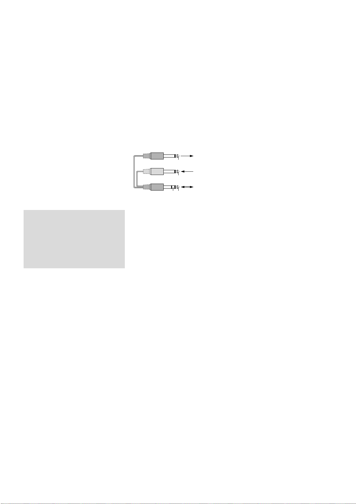
Zum Anschluss von Effektgeräten mit getrennten Ein- und Ausgangsbuchsen werden Y-Kabel
benötigt, z. B. MCA-202 von MONACOR:
schwarz
rot
schwarz
Abb. 6 Anschluss über das Y-Kabel MCA-202
SEND
RETURN
Signal
Signal
Signal
Eingang
Effektgerät
Ausgang
Effektgerät
Buchse
INSERT
4.2.2 Ausspielwege verwenden
Über die Ausspielwege 1 und 2 können Signalanteile aus den Eingangskanälen ausgekoppelt,
über ein Effektgerät (z. B. Hallgerät) bearbeitet
und über die Return-Eingänge wieder in das
Mischpult zurückgeführt werden. Der Signalabgriff für einen als Effektweg genutzten Ausspielweg ist üblicherweise post-fader, d. h. das
Kanalsignal wird nach dem Fader(1) auf den
Ausspielweg gemischt. Auf diese Weise ist der
Effektanteil eines Kanals immer proportional
zum eingestellten Kanalpegel. Der Ausspielweg1 ist für jeden Kanal durch Drücken der
Taste PRE (10) von post-fader auf pre-fader umschaltbar. Der Ausspielweg 2 ist fest auf postfader eingestellt. Er dient gleichzeitig als Effektweg für den internen Effektprozessor.
1)
Je nachdem welcher Ausspielweg genutzt
wird, den Eingang des Effektgerätes über einen 6,3-mm-Klinkenstecker mit dem MonoAusgang AUX SEND 1 oder 2 (55) verbinden.
2)
Für die Rückführung des vom Effektgerät
kommenden Signals stehen die Eingänge
AUX RTN (56) und FX RTN (57) zur Verfügung:
− Bei Verwendung des Eingangs AUX RTN
lässt sich das Effektsignal mit dem Regler AUX RTN (31) entweder auf die Summenkanäle MASTER mischen [Taste MASTER / SUB 1-2 (39) ausgerastet] oder auf die
Subgruppenkanäle [Taste MASTER / SUB 1-2
hineingedrückt].
Hinweis: Bei Anschluss eines Mono-Geräts
nur die Buchse L verwenden. Das Signal wird
dann intern auf den rechten und linken Kanal
geleitet.
− Bei Verwendung des Eingangs FX RTN lässt
sich das Effektsignal mit dem Regler FX RETURN (27) auf die Summenkanäle mischen
und mit dem Regler RETURN TO AUX 1 (37)
auf den Ausspielweg 1.
Hinweis: Der Anschluss der Buchse L und R
dieses Eingangs unterbricht jeweils den Signalweg vom linken und rechten Kanal des internen Effektprozessors zu den Summenkanälen.
Alternativ können die Signale vom Effektgerät auch auf den Line-Eingang eines freien
Eingangskanals gegeben werden.
4.3 Aufnahmegerät
Ein Aufnahmegerät kann an die Cinch-Buchsen TAPE (23) angeschlossen werden (L = linker
Kanal, R = rechter Kanal):
1)
Für die Wiedergabe den Ausgang des Gerätes an die Buchsen TAPE IN anschließen.
2) Für die Aufnahme den Eingang des Gerätes
an die Buchsen TAPE OUT anschließen. Hier
liegt das mit den Fadern MASTER (34) eingestellte Summensignal an.
4.4 Regie-Monitoranlage und
Kopfhörer anschließen
Über einen Kopfhörer und /oder über eine Monitoranlage in einem separaten Regieraum lassen
sich die Signale der einzelnen Eingangskanäle,
die Summensignale, die Subgruppensignale und
die Eingangssignale der Buchsen TAPE IN (23)
und der USB-Buchse (45) abhören. Den Kopfhörer (Mindestimpedanz 8 Ω) an die Buchse
PHONES (52) anschließen. Den Verstärker der
Monitoranlage an die Buchsen BOOTH OUT
(53) anschließen; diese Ausgangsbuchsen sind
asymmetrisch beschaltet.
4.5 Monitoranlage für die Musiker
Beim Einsatz einer Monitoranlage für die Bühnenbeschallung lässt sich der Ausspielweg 1
als Monitorweg nutzen. Der Signalabgriff für
einen als Monitorweg genutzten Ausspielweg
ist üblicherweise pre-fader, d. h. das Kanalsignal
wird vor dem Fader (1) auf den Ausspielweg
gemischt. So erhalten die Musiker über die Bühnenmonitore ein separat abgemischtes Musiksignal. Der Ausspielweg 1 lässt sich durch Drücken der Tasten PRE (10) für jeden Eingangskanal
auf pre-fader schalten.
Den Verstärker der Monitoranlage oder eine
aktive Monitorbox mit der Mono-Ausgangsbuchse AUX SEND 1 (55) verbinden.
4.6 Verstärker für die Saalbeschallung
Das Stereo-Summensignal steht an den Ausgängen MASTER (50) zur Verfügung:
1. XLR-Buchsen, symmetrisch beschaltet
2. 6,3-mm-Klinkenbuchsen, asym. beschaltet
(L = linker Kanal, R = rechter Kanal).
An einen der Ausgänge kann der Verstärker für
die Saalbeschallung angeschlossen werden. Der
zweite lässt sich gleichzeitig verwenden, z. B.
für einen zweiten Verstärker oder um das Summensignal auf ein zusätzliches Gerät zu leiten.
4.7 Betrieb mit einem Computer
Über die USB-Buchse (45) können Audiodaten
in beide Richtungen zwischen Mischpult und
Computer übertragen werden:
− Verwendung als Eingang: Über die USB-Buchse
eingespeiste Daten lassen sich mit der Taste
TAPE / USB TO MIX (41) auf das Summensignal
schalten sowie über einen Kopfhörer und eine
Regie-Monitoranlage abhören.
− Verwendung als Ausgang: Die USB-Buchse
gibt das mit den Fadern MASTER (34) eingestellte Summensignal aus.
Für den Betrieb des Mischpults mit einem Computer kann die mit dem Betriebssystem mitgelieferte Audio-Software verwendet werden oder
6

zusätzlich installierte Audio-Software. Verschiedene Audio-Programme zur Aufnahme und
Wiedergabe sind kostenlos im Internet erhältlich.
1)
Den Computer hochfahren und die USBBuchse (45) mit einem USB-Anschluss am
Computer verbinden.
2)
Das eingeschaltete Mischpult wird vom Computer als USB-Audiogerät für die Toneingabe
und Tonausgabe erkannt. Die erforderlichen
Treiber (Standard-Treiber des Betriebssystems)
sollten auf dem Computer vorhanden sein.
Hinweis: Befinden sich nicht alle geforderten
Treiber auf dem Computer, müssen sie nachinstalliert werden, z. B. über die Betriebssystem-Original-CD. Gegebenenfalls nach der Installation den Computer neu starten.
3)
Das verwendete Audio-Programm aufrufen
und dort die erforderlichen Einstellungen für
die Tonwiedergabe über das Mischpult bzw.
Tonaufnahme vom Mischpult vornehmen
(☞Anleitung des Programms). Das Mischpult
kann dann anhand Kapitel 5 bedient werden.
Findet keine Tonaufnahme bzw. Tonwiedergabe
statt, in den Systemeinstellungen des Computers
überprüfen, ob die USB-Schnittstelle für die Toneingabe bzw. Tonausgabe angewählt ist.
Tipp: Ist das Mischpult sowohl mit einem Computer
verbunden als auch mit Geräten, die über ihr Netzkabel geerdet sind (z. B. Verstärker), können aufgrund
von Masseschleifen Brummstörungen auftreten. Um
diese zu beseitigen, kann das Mischpult über ein
Massetrennfilter (z. B. FGA-102 oder FGA-202) mit
dem jeweiligen Gerät verbunden werden.
4.8 Ausgänge der Subgruppen
Die Subgruppensignale können mit den Tasten
SUB ASSIGN TO MASTER (26) auf die Signalsumme geschaltet werden und stehen aber auch
gleichzeitig an den Ausgängen SUB OUT (54)
zur Verfügung. Von diesen Ausgängen lassen
sie sich z. B. auf ein weiteres Mischpult oder auf
ein separates Effektgerät weiterleiten.
4.9 Fußtaster für den Effektprozessor
Zum Ein- und Ausschalten des internen Effektprozessors lässt sich ein Fußtaster, z. B. FS-60 von
MONACOR, an die zweipolige 6,3-mm-Klinkenbuchse FOOT SWITCH (51) anschließen.
4.10 Stromversorgung
Das Mischpult über die Netzbuchse (46) mit
dem beiliegenden Netzkabel an eine Steckdose
(230 V/ 50 Hz) anschließen.
5 Bedienung
VORSICHT
das Gehör schädigen! Das Ohr gewöhnt sich
an hohe Lautstärken und empfindet sie nach
einiger Zeit als nicht mehr so hoch. Erhöhen
Sie darum eine hohe Lautstärke nach der Gewöhnung nicht weiter.
5.1 Ein- und Ausschalten
1)
Um Einschaltgeräusche und eine zu hohe
Lautstärke zu vermeiden, vor der Inbetriebnahme folgende Ausgangsregler auf Minimum stellen:
− MASTER (34)
− BOOTH / PHONES (33)
Stellen Sie die Lautstärke der
Audioanlage und des Kopfhörers nie sehr hoch ein. Hohe
Lautstärken können auf Dauer
− AUX SEND MASTER / MON (30), wenn der
Ausspielweg 1 als Monitorweg genutzt
wird.
2)
Je nachdem welcher Mikrofontyp angeschlossen ist, die 48-V-Phantomspeisung mit
dem Schalter PHANTOM (49) entweder einoder ausschalten (
3)
Zum Ein- und Ausschalten des Mischpults
den Netzschalter POWER (48) betätigen. Bei
eingeschaltetem Gerät leuchtet die Betriebsanzeige POWER ON (36).
Kapitel 4.1.1).
☞
5.2 Aussteuerung der Eingangskanäle
Die folgenden Bedienschritte dienen nur als
Hilfestellung, es sind auch andere Vorgehensweisen möglich.
1)
Zuerst folgende Grundeinstellung vornehmen.
a) In allen Mono-Eingangskanälen (Abb. 1)
die Regler GAIN (20), die Klangregler
HIGH (17), MID (13), LOW (12) und die
Regler PAN (7) in die Mitte drehen. Die
Tasten (18) ausrasten.
b) In allen Stereo-Eingangskanälen (Abb.2)
die Klangregler HIGH (17), MID 3 kHz
(16), MID 500 Hz (14), LOW (12) und die
Regler BAL (8) in die Mitte drehen. Im
Kanal CH 9 / 10 die Taste +4 /−10 (19) ausrasten und im Kanal CH 11/12 die Taste
LINE / OPT(19).
c) In allen Eingangskanälen die Regler AUX
SEND 1 / MON (11) und AUX SEND 2 / FX (9)
für die Ausspielwege ganz zurückdrehen.
d)
In allen Eingangskanälen die Tasten MUTE
(6), 1-2 (4), L-R (3) und SOLO (2) ausrasten
sowie die Kanalfader (1) zuziehen.
e)
Im Ausgangsfeld (Abb. 3) alle Tasten SOLO
(29) und die Taste TAPE / USB TO MIX (41)
ausrasten sowie die AUX-SEND-MASTERRegler (28, 30) und die RETURN-Regler
(27, 31, 37) zudrehen.
2) Auf den ersten verwendeten Kanal ein Tonsignal geben (z. B. in ein Mikrofon singen, ein
Instrument spielen).
3)
Soll das Signal über den angeschlossenen
Verstärker für die Saalbeschallung zu hören
sein, den Fader (1) des Kanals bis zur Position
„0“ aufziehen, die Taste L-R (3) drücken und
die Fader MASTER (34) so weit aufziehen,
dass das Signal gut zu hören ist. Das Signal
lässt sich aber auch bei zugezogenen Fadern
über einen Kopfhörer oder eine Regie-Monitoranlage abhören, ☞ Kap. 5.6.
4)
Die Taste SOLO (2) des Kanals drücken.
Damit ist die Abhörfunktion für den Kanal
eingeschaltet, zur Kontrolle leuchtet die LED
PEAK(5).
5)
Die Taste PFL /AFL (40) ggf. ausrasten, um
den Abhörmodus „PFL“ zu wählen: Die LED
unter der Taste leuchtet grün und die linke
LED-Reihe der Aussteuerungsanzeige (38)
zeigt das Kanalsignal vor dem Fader (1) und
dem Regler PAN (7) bzw. BAL (8) an.
6) Anhand der Aussteuerungsanzeige die Eingangsverstärkung optimal einstellen:
Bei einem Mono-Kanal den Regler GAIN
(20) so einstellen, dass ein Pegel im Bereich
um 0 dB angezeigt wird.
Wird der Stereo-Kanal CH 9/10 trotz
ausgerasteter Taste +4 /−10 (19) übersteuert,
muss der Pegel der Signalquelle verringert
werden. Bei geringer Aussteuerung zur Pegelanhebung (12 dB) die Taste +4 /−10 drücken.
Bei dem Stereo-Kanal CH 11 / 12 ist die
Eingangsverstärkung fest eingestellt. Wenn
die Aussteuerung ungünstig ist, den Ausgangspegel der angeschlossenen Signalquelle verändern.
7)
Den Klang mit den Reglern HIGH (17) für die
Höhen und LOW (12) für die Bässe einstellen
(±15 dB).
Bei einem Mono-Kanal mit dem Regler
MID FREQ (15) die Mittenfrequenz einstellen
(100 – 8000 Hz) und deren Anhebung oder
Absenkung (15 dB) mit dem Regler MID (13).
Bei Bedarf die Taste (18) zum Unterdrücken tieffrequenter Störgeräusche (z. B. Trittschall, Brummen) drücken.
Bei einem Stereo-Kanal die Mitten mit
den Reglern MID 500 Hz (14) und MID 3 kHz
(16) einstellen (±15 dB).
Anschließend die Aussteuerung des Kanals überprüfen und ggf. die Eingangsverstärkung korrigieren.
8)
Die Taste SOLO wieder ausrasten, um die
Abhörfunktion für den Kanal auszuschalten.
Bei ausgeschalteter Abhörfunktion dient die
LED PEAK als Übersteuerungsanzeige, mit
der sich die Aussteuerung des Kanals grob
kontrollieren lässt. Leuchtet sie permanent,
die Eingangsverstärkung (Regler GAIN) oder
das Eingangssignal reduzieren.
9) Damit bei der Wiedergabe des Signals über
den Verstärker zur Saalbeschallung immer
nur der Kanal zu hören ist, der gerade eingestellt wird, nach der Aussteuerung eines
Kanals seinen Fader (1) zurück auf Minimum
stellen oder zum Stummschalten seine Taste
MUTE (6) drücken.
10)
Für alle weiteren Eingangskanäle die Bedienschritte 2) bis 9) wiederholen.
5.3 Eingangssignale mischen
1) Für jeden Eingangskanal wählen, ob die Kanalsignale auf die Summenkanäle oder / und
auf die Subgruppenkanäle gemischt werden
sollen:
− Durch Drücken der Taste L-R (3) werden die
Signale auf die Summenkanäle MASTER
geleitet.
− Durch Drücken der Taste 1-2 (4) werden die
Signale auf die Kanäle SUB 1 und 2 geleitet. Diese Signale lassen sich gemeinsam
mit den Fadern SUB 1 und 2 (24) ein- und
ausblenden oder in der Lautstärke verändern und bei Bedarf über die Buchsen
SUB OUT (53) auf ein separates Effektgerät
leiten.
2)
Die Fader MASTER (34) so weit aufziehen,
dass sich das Mischungsverhältnis der Tonquellen optimal einstellen lässt.
3) Die Signale der Eingangskanäle mit den Fadern (1) im gewünschten Lautstärkeverhältnis mischen. Die Fader nicht benutzter Kanäle
immer ganz zuziehen.
4) Für die Mono-Kanäle mit den Panoramareglern PAN (7) die Mono-Signale im StereoKlangbild platzieren und für die StereoKanäle mit den Reglern BAL (8) die Balance
der Stereo-Signale einstellen.
5)
Werden Signale auf die Subgruppen geleitet,
die entsprechenden Tasten SUB ASSIGN TO
MASTER (26) drücken, wenn die Subgruppen
auf den linken und rechten Summenkanal
gemischt werden sollen. (In der Regel im
Kanal SUB 1 die Taste L hineindrücken und
Deutsch
7

im Kanal SUB 2 die Taste R.) Die Lautstärke
der Subgruppensignale mit den Fadern SUB
1 und 2 (24) einstellen.
6)
Zum Zumischen von Effekten siehe Kap.5.5.
Deutsch
7) Um das Eingangssignal der Buchsen TAPE IN
(23) und der USB-Buchse (45) auf die Signalsumme zu schalten, die Taste TAPE / USB TO
MIX (41) drücken.
Hinweis: Wird während einer Aufnahme über
die Buchsen TAPE OUT bzw. die USB-Buchse das
Aufnahmesignal als Eingangssignal auf die Buchsen TAPE IN bzw. die USB-Buchse gegeben, darf
die Taste TAPE / USB TO MIX nicht hineingedrückt
sein, da sonst eine Rückkopplung auftritt.
8)
Mit den Fadern MASTER die endgültige Lautstärke des Summensignals unter Beachtung
der Aussteuerungsanzeige (38) einstellen.
Damit diese den Pegel des Summensignals
anzeigt, die Taste MASTER MIX (32) hineindrücken. Es müssen dabei alle Tasten SOLO
(2, 29) für die Abhörfunktion ausgerastet
sein. [Falls eine der Tasten SOLO hineingedrückt ist, leuchtet die LED unter der Taste
PFL /AFL (40).] Bei Übersteuerung leuchten
die roten LEDs CLIP der Pegelanzeige auf; die
Fader MASTER dann entsprechend zuziehen.
9)
Zum Stummschalten eines Kanals, z. B. während einer Spielpause, die Taste MUTE (6,
25) drücken. Zur Kontrolle leuchtet die LED
unter der Taste.
5.4 Monitor-Ausspielweg einstellen
Die Monitoranlage für die Bühnenbeschallung
muss an der Buchse AUX SEND 1 (55) des Ausspielwegs 1 angeschlossen sein.
1)
Bei den Kanälen, die auf den Monitorweg
gegeben werden, die Taste PRE (10) drücken,
um den Signalabgriffspunkt für den Monitorweg auf pre-fader umzuschalten.
2)
Den Regler AUX SEND MASTER 1 / MON
(30) für die Gesamtlautstärke der Monitormischung so weit aufdrehen, dass das Monitorsignal bei den folgenden Einstellungen gut
über die Monitoranlage zu hören ist.
3)
Mit den Reglern AUX SEND 1 / MON (11) die
Kanalsignale auf den Monitorweg mischen:
Die Regler je nach gewünschtem Lautstärkeverhältnis der Kanäle aufdrehen.
4) Mit dem Regler RETURN TO AUX 1 (37) lässt
sich das Effektsignal des internen Effektprozessors auf den Monitorweg 1 mischen oder
das Signal von den Buchsen FX RTN (57),
wenn dort ein Gerät angeschlossen ist.
5) Soll der Monitorweg über einen Kopfhörer
oder eine Regie-Monitoranlage abgehört
werden und die Aussteuerungsanzeige (38)
das Monitorsignal anzeigen, die Taste SOLO
(29) neben dem Regler AUX SEND MASTER1 /
MON (30) drücken, ☞ Kap. 5.6.
5.5 Effekte zumischen
5.5.1 Verwendung des internen Effektprozessors
Mit dem internen Effektprozessor lassen sich
100 verschiedene Effekte erzeugen, die auf die
Summenkanäle MASTER und auf den Ausspielweg 1 gemischt werden können. Als Effektweg
für den Effektprozessor dient der Ausspielweg 2.
Wichtig: Wird der Effektprozessor genutzt,
darf der Eingang FX RTN (57) nicht belegt sein.
Beim Anschluss der beiden Buchsen wird der
Signalweg vom internen Effektprozessor zu
den Summenkanälen und zum Ausspielweg1
unterbrochen.
1)
Damit die nachfolgenden Effekteinstellungen
zu hören sind, die Regler AUX SEND MASTER 2 / FX (28) und FX RETURN (27) vorerst
ungefähr auf Mittelposition stellen.
2)
Den Drehknopf FX SELECT (43) links- oder
rechtsherum drehen, bis die Nummer des
gewünschten Effekts (☞ Abb. 7 Effektübersicht) blinkend im Display (44) angezeigt
wird. Die Wahl durch Drücken des Knopfes
bestätigen: Die Nummer hört auf zu blinken,
der Effekt ist eingeschaltet.
3)
Mit den Reglern AUX SEND 2 / FX (9) die
Signale der Eingangskanäle auf den Effektweg mischen. Der Signalabgriff ist nach dem
Fader (1), d. h. der Effektanteil eines Kanals
ist immer proportional zum eingestellten
Kanalpegel.
4) Den Pegel aller auf den Effektweg gemisch-
ten Signale mit dem Regler AUX SEND MASTER 2 / FX (28) einstellen. Die Signale werden
auf den Eingang des Effektprozessors gegeben und liegen auch an der Buchse AUX
SEND 2 (55) an.
Die LED PEAK über der Taste MUTE (42)
dient bei eingeschaltetem Effektprozessor als
Übersteuerungsanzeige. Mit ihr lässt sich die
Aussteuerung grob kontrollieren. Leuchtet
sie auf, den Regler AUX SEND MASTER2 /
FX entsprechend zurückdrehen.
5) Das Effektsignal mit dem Regler FX RETURN
(27) auf die Summenkanäle mischen und mit
dem Regler RETURN TO AUX 1 (37) wenn
gewünscht auch auf den Ausspielweg 1.
6) Der Effektprozessor lässt sich mit einem an
der Buchse FOOT SWITCH (51) angeschlossenen Fußtaster und mit der Taste MUTE (42)
aus- und wieder einschalten (die Taste rastet
nicht ein). Ist er ausgeschaltet, leuchtet zur
Kontrolle die LED PEAK über der Taste MUTE.
5.5.2 Externes Effektgerät
Das Effektgerät muss über einen Aux-SendAusgang und einen Aux-Return-Eingang (oder
Line-Eingang eines freien Eingangskanals) angeschlossen sein, ☞Kapitel 4.2.2.
1)
Damit die nachfolgenden Effekteinstellungen
zu hören sind, den zugehörigen Ausgangsund Eingangsregler vorerst ungefähr in die
Mittelposition stellen:
entsprechend des verwendeten Ausgangs
Regler AUX SEND MASTER 1 / MON (30)
oder
Regler AUX SEND MASTER 2 / FX (28)
entsprechend des verwendeten Eingangs
Regler AUX RTN (31)
oder
Regler FX RETURN (27)
oder
Fader (1) des entsprechenden Eingangskanals
2)
Ist das Effektgerät am Eingang AUX RTN
(56) angeschlossen, mit der Taste MASTER / SUB1-2 (39) festlegen, ob das Effektsignal entweder auf die Summenkanäle (Taste
ausgerastet) oder auf die Subgruppenkanäle
(Taste hineingedrückt) geleitet werden soll.
3) Je nachdem welcher Ausspielweg als Effektweg genutzt wird, mit den Reglern AUX
SEND 1 / MON (11) oder mit den Reglern
AUX SEND 2 / FX (9) die Kanalsignale auf den
Effektweg mischen. Mit diesen Reglern lässt
sich für jeden Kanal getrennt die gewünschte
Effektintensität einstellen.
Wird der Ausspielweg 1 als Effektweg
genutzt, müssen die Tasten PRE (10) ausgerastet sein (Einstellung post-fader).
Hinweis: Ist das Effektgerät am Line-Eingang
eines Eingangskanals angeschlossen, den Regler
AUX SEND 1 bzw. 2 des betreffenden Kanals ganz
zurückdrehen, sonst tritt eine Rückkopplung auf.
4)
Mit dem jeweiligen AUX-SEND-Ausgangsregler (28, 30) den Pegel für das Ausgangssignal des Effektwegs so einstellen, dass das
Effektgerät nicht übersteuert wird.
Mit der Taste SOLO (29) neben dem AUXSEND-Regler lässt sich der Effektweg über
einen Kopfhörer oder eine Regie-Monitoranlage abhören und über die Aussteuerungsanzeige (38) kontrollieren, ☞Kapitel 5.6.
5) Das vom Effektgerät kommende Signal mit
dem jeweiligen Eingangsregler zumischen;
mit ihm lässt sich die Effektintensität für alle
Kanäle gemeinsam einstellen:
− Ist das Effektgerät am Eingang AUX RE-
TURN (56) angeschlossen,
das Effektsignal mit dem Regler AUX
RTN(31) auf die Summenkanäle mischen
oder auf die Subgruppenkanäle (je nach
Stellung der Taste MASTER / SUB1-2).
− Ist das Effektgerät am Eingang FX RTN (57)
angeschlossen,
das Effektsignal mit dem Regler FX RETURN
(27) auf die Summenkanäle mischen. Zusätzlich kann das Effektsignal mit dem Regler RETURN TO AUX 1 (37) auf den Aus-
Nummer
00 – 09 VOCAL Nachhalleffekt, besonders für Gesangsanwendungen geeignet Abklingzeit 0,8 – 0,9 s, Pre-Delay-Zeit 10 – 45 ms
10 – 19 SMALL ROOM Nachhalleffekt: Simulation eines kleinen bis mittelgroßen Raums Abklingzeit 0,7 – 2,1 s, Pre-Delay-Zeit 20 – 45 ms
20 – 29 LARGE HALL Nachhalleffekt: Simulation eines großen Saals Abklingzeit 3,6 – 5,4 s, Pre-Delay-Zeit 23 – 55 ms
30 – 39 ECHO Echo-Effekt Delay-Zeit 145 – 205 ms
40 – 49 ECHO + VERB Kombination von Echo-Effekt und Nachhalleffekt Delay-Zeit 208 – 650 ms, Abklingzeit 1,7 – 2,7 s
50 – 59 FLANGE + VERB Kombination von Flanger-Effekt und Nachhalleffekt Geschwindigkeit 0,8 – 2,52 Hz, Abklingzeit 1,5 – 2,9 ms
60 – 69 PLATE Simulation einer klassischen, hell klingenden Hallplatte Abklingzeit 0,9 – 3,6 s
70 – 79 CHORUS + GTR Gitarreneffekt: Chorus Geschwindigkeit 0,92 – 1,72 Hz
80 – 89 ROTARY + GTR Gitarreneffekt: Rotary (Leslie-Effekt) Modulationstiefe 20 – 80 %
90 – 99 TREMOLO + GTR Gitarreneffekt: Tremolo Geschwindigkeit 0,6 – 5 Hz
Abb. 7 Effektübersicht
Name Effekt Parameter
8
spielweg 1 gemischt werden (z. B. wenn
dieser als Monitorweg genutzt wird).
− Ist das Effektgerät am Line-Eingang (21)
eines Eingangskanals angeschlossen,
das Effektsignal mit dem entsprechenden
Kanalfader (1) auf die Summenkanäle
mischen [die Taste L-R (3) muss hineingedrückt sein] und /oder auf die Subgruppenkanäle [die Taste 1-2 (4) muss hineingedrückt sein].
5.5.3 Separates Effektgerät
fürdieSubgruppen
Unabhängig von den in den Kapiteln 5.5.1 und
5.5.2 beschriebenen Möglichkeiten, lassen sich
die Signale der Subgruppen über ein separates
Effektgerät leiten.
1) Den Eingang des Effektgerätes an die Buch-
sen SUB OUT (54) anschließen und den
Effektgerätausgang an einen freien LineEingang des Mischpults.
2)
Mit den Tasten SUB ASSIGN TO MASTER (26)
wählen:
− Sollen die Signale der Subgruppen komplett über das Effektgerät geleitet und von
dort auf die Summenkanäle gemischt werden, alle Tasten ausrasten.
− Sollen die Signale der Subgruppen im Mischpult auf die Summenkanäle gemischt und
die Effektsignale der Subgruppen auf die
Summenkanäle dazu gemischt werden,
die entsprechenden Tasten drücken (in der
Regel im Kanal SUB 1 die Taste L und im
Kanal SUB 2 die Taste R).
3) Mit den Fadern SUB 1 und 2 (24) den Pegel
einstellen, mit dem die Signale der Subgruppen auf das Effektgerät gegeben und eventuell auch auf die Summenkanäle gemischt
werden.
4)
Alle weiteren Einstellungen am Effektgerät
und am Eingangskanal, an dem das Effektgerät angeschlossen ist, durchführen.
5.6 Abhören über einen Kopfhörer
und eine Regie-Monitoranlage
Zum Abhören über einen Kopfhörer an der
Buchse PHONES (52) und eine Regie-Monitoranlage an den Buchsen BOOTH OUT (53) lassen
sich folgende Signale anwählen:
1. das Signal jedes Eingangskanals
2.
die Gesamtsignale der Ausspielwege 1 und 2
3.
die Eingangssignale der Buchsen TAPE IN (23)
und der USB-Buchse (45)
4. die Signale der Subgruppen 1 und 2 an den
Ausgängen SUB OUT (54)
5.
die Summensignale des Mischpults an den
Ausgängen MASTER (50)
Die Aussteuerungsanzeige (38) zeigt immer den
Pegel der Signale an, welche zum Abhören ausgewählt sind.
1)
Zum Abhören eines Eingangskanals die
Taste SOLO (2) des Kanals drücken. Zur Anzeige, dass die Abhörfunktion für den Kanal
eingeschaltet ist, leuchtet die LED PEAK (5).
Zusätzlich leuchtet unter der Taste PFL /AFL
(40) die LED: grün im Abhörmodus „PFL“
oder rot im Modus „AFL“.
− Bei ausgerasteter Taste PFL /AFL ist der
Modus „PFL“ (pre fader listening) einge
schaltet. Dieser kann für die Einpegelung
eines Kanals genutzt werden: Das Kanalsignal wird vor dem Fader (1) und dem Panorama- (7) bzw. Balanceregler (8) abgehört
und angezeigt (mono).
− Bei hineingedrückter Taste PFL /AFL ist
der Modus „AFL“ (after fader listening)
eingeschaltet, mit dem sich die gesamte
Kanaleinstellung kontrollieren lässt: Das
Kanalsignal wird nach dem Fader und dem
Panorama- bzw. Balanceregler abgehört
und angezeigt (stereo).
2)
Zum Abhören eines Ausspielwegs die zugehörige Taste SOLO (29) drücken:
für den Ausspielweg 1 die SOLO-Taste neben
dem Regler AUX SEND MASTER 1 (30),
für den Ausspielweg 2 die SOLO-Taste neben
dem Regler AUX SEND MASTER 2 (28).
Mit der Taste PFL /AFL den Abhörmodus wählen: Ist die Taste ausgerastet, wird das Signal
vor dem Regler AUX SEND MASTER abgehört
und angezeigt, bei hineingedrückter Taste
nach dem Regler.
3)
Zum Abhören des Eingangssignals der Buchsen TAPE IN (23) und der USB-Buchse (45),
z. B. um eine Aufnahme zu kontrollieren, die
Taste CD / USB / TAPE (32) drücken.
4)
Zum Abhören der Subgruppensignale (immer
post-fader) die Taste SUB 1-2 (32) drücken.
5)
Zum Abhören der Summensignale (immer
post-fader) die Taste MASTER MIX (32) drücken.
Wichtig: Die Tasten SOLO (2, 29) haben Vorrang
vor den Tasten BOOTH (32), d. h. wenn mindestens eine Taste SOLO hineingedrückt ist, werden
die mit den Tasten BOOTH gewählten Signale
nicht abgehört / angezeigt. Die Tasten BOOTH
sind dagegen untereinander gleichrangig, d. h.
sind sie gleichzeitig hineingedrückt, wird das
Mischsignal der zugehörigen Quellen abgehört
und angezeigt.
6 Technische Daten
Eingänge
(Empfindlichkeit / Impedanz; Anschluss)
Mic: � � � � � � � � � � � � � � � 0,5 mV/1,8 kΩ;
XLR, symmetrisch
Line (Mono-Kanal): � � � 1 mV/10 kΩ;
6,3-mm-Klinke, sym�
Line (Stereo-Kanal): � � � 10 mV/10 kΩ;
6,3-mm-Klinke, sym�
Tape In: � � � � � � � � � � � � 100 mV/10 kΩ; Cinch
Return: � � � � � � � � � � � � 100 mV/10 kΩ;
6,3-mm-Klinke, asym�
Insert: � � � � � � � � � � � � � 100 mV/10 kΩ;
6,3-mm-Klinke, asym�
Ausgangspegel
Master
XLR-Buchsen: � � � � � � 1,5 V*
Klinken-Buchsen: � � � 750 mV*
Tape Out: � � � � � � � � � � � 750 mV*
Booth Out: � � � � � � � � � � 2 V*
*bei Anzeige 0 dB
Aux Send: � � � � � � � � � � max� 9,5 V
Kopfhörerimpedanz: � � � � � ≥ 8 Ω
USB-Schnittstelle: � � � � � � � USB 2�0 (Full Speed)
-
Frequenzbereich: � � � � � � � � 20 – 20 000 Hz
Klirrfaktor: � � � � � � � � � � � � � < 0,05 %
Störabstand: � � � � � � � � � � � > 74 dB (A-bewertet)
Übersprechen: � � � � � � � � � � −63 dB
Klangregler
Bässe: � � � � � � � � � � � � � ±15 dB / 80 Hz
Höhen: � � � � � � � � � � � � � ±15 dB / 12 kHz
Mitten Mono-Kanal: � � � ±15 dB / 100 – 8000 Hz
Mitten Stereo-Kanal: � � ±15 dB / 500 Hz
±15 dB / 3000 Hz
Low-Cut-Filter: � � � � � � � � � 75 Hz
Phantomspeisung: � � � � � � � +48 V
Stromversorgung:
� � � � � � � 230 V/ 50 Hz
Leistungsaufnahme: � � � � � max� 40 VA
Einsatztemperatur: � � � � � � 0 – 40 °C
Abmessungen (B × H × T): 404 × 96 × 385 mm
Gewicht: � � � � � � � � � � � � � � 5,2 kg
Geeignete Betriebssysteme für den Datentransfer
über die USB-Schnittstelle:
Windows 2000, Windows XP oder nachfolgende
Windows-Versionen
Mac OS 9.0.4 oder höher, Mac OS X
Windows ist ein registriertes Warenzeichen der Microsoft Corporation in den USA und anderen Ländern.
Mac OS ist ein registriertes Warenzeichen von Apple Inc. in den USA
und anderen Ländern.
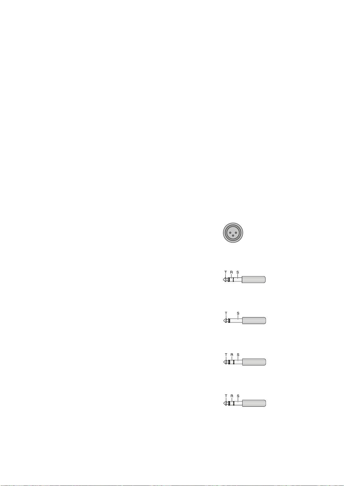
6.1 Steckerbelegung XLR und Klinke
XLR-Stecker für symmetrischen Anschluss
1 = Masse
2 1
3
2 = Signal +
3 = Signal −
3-poliger 6,3-mm-Klinkenstecker
für symmetrischen Anschluss
T = Signal +
R = Signal −
S = Masse
2-poliger 6,3-mm-Klinkenstecker
für asymmetrischen Anschluss
T = Signal
S = Masse
3-poliger 6,3-mm-Klinkenstecker
für die INSERT-Buchsen
T = Send (Ausgang)
R = Return (Eingang)
S = Masse
6,3-mm-Stereo-Klinkenstecker
für den Kopfhöreranschluss
T = linker Kanal
R = rechter Kanal
S = Masse
Änderungen vorbehalten.
Deutsch
Diese Bedienungsanleitung ist urheberrechtlich für MONACOR ® INTERNATIONAL GmbH & Co. KG
geschützt. Eine Reproduktion für eigene kommerzielle Zwecke – auch auszugsweise – ist untersagt.
9

Audio Mixer
These operating instructions are intended for
users with basic knowledge in audio technology.
English
Please read the instructions carefully prior to
operation and keep them for later reference.
All operating elements and connections
described can be found on the fold-out page 3.
Contents
1 Overview . . . . . . . . . . . . . . . . 10
1.1 Input channels. . . . . . . . . . . . 10
1.2 Output panel . . . . . . . . . . . . 10
1.3 Rear panel . . . . . . . . . . . . . . 11
2 Safety Notes . . . . . . . . . . . . . . 11
3 Applications. . . . . . . . . . . . . . . 11
4 Connecting Units . . . . . . . . . . . 12
4.1 Audio sources . . . . . . . . . . . . 12
4.1.1 Microphones . . . . . . . . . . . . 12
4.1.2 Line audio sources . . . . . . . . . 12
4.2 Effect units . . . . . . . . . . . . . 12
4.2.1 Inserting effect units . . . . . . . . 12
4.2.2 Using send ways . . . . . . . . . . 12
4.3 Recorder. . . . . . . . . . . . . . . 12
4.4 Connecting a control monitor
system and headphones . . . . . . . 12
4.5 Monitor system forthemusicians . . 12
4.6 Amplifier for PA applications inhalls. 12
4.7 Operation with a computer . . . . . 12
4.8 Outputs of the subgroups . . . . . . 13
4.9 Foot pedal for the effectprocessor . 13
4.10 Power supply . . . . . . . . . . . . 13
5 Operation . . . . . . . . . . . . . . . . 13
5.1 Switching on and off . . . . . . . . 13
5.2 Level control of the inputchannels . 13
5.3 Mixing input signals . . . . . . . . . 13
5.4 Adjusting the monitor send way . . . 14
5.5 Adding effects. . . . . . . . . . . . 14
5.5.1 Using the internal effect processor . 14
5.5.2 External effect unit . . . . . . . . . 14
5.5.3 Separate effect unit
for the subgroups. . . . . . . . . . 15
5.6 Monitoring via headphones
and a control monitor system . . . . 15
6 Specifications. . . . . . . . . . . . . . 15
6.1 Pin configuration of XLR and
6.3 mm plugs . . . . . . . . . . . . 15
1 Overview
1.1 Input channels
Fig. 1 Mono input channel CH 1; the other
mono input channels are identical.
Fig. 2 Stereo input channel CH 9 /10; with the
exception of the button of item 19, the second
stereo input channel is identical.
1 Channel fader to adjust the volume of the
channel and to fade in / fade out the channel
signal
2 Button SOLO to monitor the selected chan-
nel via the headphones connected to the
jack PHONES (52) and via a monitor system
connected to the jacks BOOTH OUT (53):
either for pre-fader listening when the button PFL /AFL (40) is disengaged
or for checking the overall channel adjustment after the channel fader when the button PFL /AFL is engaged
When the button SOLO is engaged, the
corresponding LED PEAK (5) will light permanently and the level indicators (38) will
indicate the corresponding channel signal.
3
Button L-R: When the button is engaged,
the channel signal will be added to the
sum channels MASTER. With the control
PAN (7) or BAL (8), the signal can be added
to the right or left channel only or to both
channels.
4
Button 1-2: When the button is engaged,
the channel signal will be added to the subgroups SUB 1 and SUB 2. With the control
PAN (7) or BAL (8), the signal can be added to
group SUB 1 or SUB 2 only or to both groups.
5
LED PEAK: When the button SOLO (2) is
engaged, the LED PEAK will light permanently. When the button SOLO disengaged,
the LED PEAK will light up briefly to indicate
that the maximum undistorted signal level
has been reached. If it lights up longer, the
channel is overloaded. In this case, turn back
the control GAIN (20) accordingly.
6 Button MUTE (with LED indicator) to mute
the channel
7 Panorama control PAN to place the mono
signal in the stereo sound
When the button 1-2 (4) is engaged, the
control PAN can be used to assign the channel signal to the subgroups.
8 Balance control
When the button 1-2 (4) is engaged, the
balance control can be used to assign the
channel signal to the subgroups.
9
Control AUX SEND 2 / FX to add the channel
signal to send way 2 (post-fader); this send
way is also used as an effect way for the
internal effect processor
10 Selector button PRE for send way 1
disengaged: signal picked-up post-fader
The channel signal is fed to the send way
after the fader (1).
engaged: signal picked up pre-fader
The channel signal is fed to the send way
ahead of the fader.
11
Control AUX SEND 1 / MON to add the channel signal to send way 1
12
Equalizer control LOW 80 Hz for the bass
frequencies:±15 dB at 80 Hz
13 Equalizer control MID for the mid-frequen-
cies: ±15 dB at 100 Hz – 8 kHz
14
Equalizer control MID 500 Hz for the mid-frequencies at 500 Hz: ±15 dB
15
Control MID FREQ to adjust the filter frequency (100 Hz – 8 kHz) for equalizer control
in the midrange
16
Equalizer control MID 3 kHz for the mid-frequencies at 3 kHz: ±15 dB
17 Equalizer control HIGH 12 kHz for the high
frequencies: ±15 dB at 12 kHz
18
Button for the low cut filter (high pass filter):
When the button is engaged, unwanted
signal parts below 75 Hz (e. g. impact noise)
will be suppressed.
19 Channel CH 9 /10:
Button +4 /−10 for matching the level of
units with low output level; when the button
is engaged, the input level will be boosted
Channel CH 11/12:
Button LINE / OPT to switch the channel input
disengaged: input = jacks LINE (21)
engaged: input = signal of an additional
module (e. g. MP3 player) which is in-
stalled in the upper right section instead
of the cover panel
20
Control GAIN to adjust the input amplifi
cation
21
Input LINE (6.3 mm jack, bal.) to connect
a signal source with line output level (e. g.
musical instrument, CD / MP3 player)
Note with regard to the stereo channels:
When connecting a mono unit, only use the
jackL. The signal will then be internally sent to
the right and left channels.
22 Input MIC to connect a microphone
(XLR jack, bal.)
A phantom power can be activated for all
microphone inputs, ☞ item 49.
23
Input and output jacks (RCA) TAPE for a
recorder
The sum signal is available at the jacks OUT
[after the faders MASTER (34)].
When the button TAPE / USB TO MIX (41)
is engaged, the signal of the jacks IN will
be added to the sum signal ahead of the
faders MASTER.
1.2 Output panel
24 Faders for the subgroups 1 and 2
25 Buttons MUTE (with LED indicator) to mute
the subgroups
26 Assign buttons SUB ASSIGN TO MASTER to
route the subgroup signals to the left or / and
right sum channel
27
Level control FX RETURN for the effect signal
of the internal effect processor or for the
signal at the input FX RETURN (57)
Use the level control to add the signal to the
sum channels MASTER.
28 Level control AUX SEND MASTER 2 / FX for
the total signal of send way 2 that is sent
to the internal effect processor and to the
output AUX SEND 2 (55)
29 Button SOLO – one for send way 1 and one
for send way 2 – to monitor the send way via
headphones connected to the jack PHONES
(52) and via a monitor system connected to
the jacks BOOTH OUT (53)
30 Level control AUX SEND MASTER 1 / MON
for the total signal of send way 1 that is
available at the output AUX SEND 1 (55)
31 Level control AUX RTN to add the signals at
the input AUX RTN (56) to the sum chan-
-
10
nels MASTER [button MASTER SUB 1-2 (39)
disengaged] or to the subgroup channels
[button engaged]
32 Buttons BOOTH to select the signals to be
monitored via the headphone jack PHONES
(52) and the output BOOTH OUT (53) and
to be indicated by the level indicators (38):
– button MASTER MIX for the output signals
of the sum channels MASTER
– button CD / USB / TAPE for the input signals
of the jacks TAPE IN (23) and of the USB
port (45)
– button SUB 1-2 for the signals of the sub-
groups 1 and 2
Notes:
1. If multiple buttons are engaged, the mixed
signal of the corresponding sources will be
monitored and indicated.
2. The monitor signals selected by means of the
buttons SOLO (2, 29) will take priority: If a
button SOLO is engaged, the corresponding signals will be monitored and indicated
instead of the signals that may have been
selected by means of the buttons BOOTH.
33
Volume control BOOTH / PHONES for the
headphone output PHONES (52) and the
output BOOTH OUT (53)
34 Faders for the sum channels
35
LED indicator PHANTOM 48 V: lights up when
phantom power for the inputs MIC(22) has
been activated
36 LED POWER ON
37
Control RETURN TO AUX 1 to add the signals
of the internal effect processor or the signals
of the jacks FX RTN (57) to send way1
38
Level indicators, indicate the level of the signal that has been selected to be monitored
via the headphone output PHONES (52) and
the output BOOTH OUT (53):
– the signals of the input channels / send
ways for which the button SOLO (2, 29)
has been engaged
– if none of the buttons SOLO has been
engaged, the monitoring signal that has
been selected by means of the button
BOOTH (32)
39
Assign button MASTER / SUB 1-2 to forward
the signals of the input AUX RTN (56) to
the sum channels MASTER (button disengaged) or to the subgroup channels (button
engaged)
40
Button PFL /AFL (with LED indicator beneath
the button):
button disengaged = PFL (pre-fader listening)
The input channels for which the button
SOLO (2) is engaged will be monitored
ahead of the control PAN (7) or BAL (8)
and the fader (1); the send ways for which
the button SOLO (29) is engaged will be
monitored ahead of the control AUX
SEND (28, 30).
button engaged = AFL (after-fader listening)
The input channels for which the button
SOLO is engaged will be monitored after
the control PAN or BAL and the fader; the
send ways for which the button SOLO
is engaged, will be monitored after the
control AUX SEND.
41
Button TAPE / USB TO MIX: When the button
is engaged, the input signals of the jacks
TAPE IN (23) and of the USB port (45) will be
sent to the sum channels MASTER.
42
Button MUTE to activate / deactivate a
se lected effect
When the effect is deactivated, the LED
PEAK above the button will light permanently. When the effect is activated, the
LED will only light up briefly if the effect
processor is overloaded.
43
Knob FX SELECT to select an effect: Turn the
knob until the appropriate effect number
starts flashing on the display. Then briefly
press the knob to confirm your selection.
44 Display EFFECT to show the effect number
selected
45
USB port (type B) to connect a computer;
can simultaneously be used as an output
(digital output of the sum signal) and as an
input (feed-in of audio data) (full-duplex
mode)
1.3 Rear panel
46
Mains jack for connection to a mains socket
(230 V/ 50 Hz) via the mains cable supplied
47 Support for the mains fuse
Always replace a blown fuse by a fuse of
the same type.
48 POWER switch
49
Switch PHANTOM of the 48 V phantom
power supply for all microphone inputs MIC
(22); when the phantom power is activated,
the LED PHANTOM 48 V (35) will light up
Please observe the warning notes with regard to the phantom power in chapter4.1.1.
50
Outputs MASTER for the sum signal, e. g.
to connect the amplifier for PA applications
in halls
– via XLR jacks,
Left L / Right R, balanced
– via 6.3 mm jacks
Left L / Right R, unbalanced
51
Connection FOOT SWITCH (6.3 mm jack,
2poles) for a foot pedal to activate / deactivate the internal effect processor
52
Output PHONES (6.3 mm jack) to connect
stereo headphones (minimum impedance:
8 Ω)
53
Output BOOTH OUT (6.3 mm jacks Left L /
Right R, unbal.) to connect a control monitor
system
54
Outputs SUB OUT (6.3 mm jacks, unbal.) for
subgroups 1 and 2
55 Outputs AUX SEND (6.3 mm jacks, unbal.)
for send ways 1 and 2
56
Inputs AUX RTN (6.3 mm jacks Left L / Right R,
unbal.), can be used as an input for an effect
unit or for an additional line audio source
Note: To connect a mono unit, only use the jack
L. The signal will then be internally sent to the
right and left channels.
57 Effect signal inputs FX RTN
(6.3 mm jacks Left L / Right R, unbal.)
When the inputs are connected, the input
signal is sent to the sum channels and the
signal way from the internal effect processor
to the sum channels is interrupted.
58 Jacks CHANNEL INSERTS (6.3 mm jacks) to
insert effect units (e. g. compressors) into the
mono input channels CH 1 to CH 8
Plug connections:
tip = Send (output)
ring = Return (input)
sleeve = Ground
2 Safety Notes
The unit corresponds to all relevant directives of
the EU and is therefore marked with .
WARNING This unit uses dangerous mains
voltage. Leave servicing to skilled
personnel. Do not insert anything into the air vents. Inexpert
handling or modification may
result in electric shock.
The unit is suitable for indoor use only. Protect
•
it against dripping water and splash water,
high air humidity and heat (admissible ambient temperature range: 0 – 40 °C).
Do not place any vessel with liquid on the unit,
•
e. g. a drinking glass.
Do not operate the unit and immediately dis-
•
connect the mains plug from the socket
1.
if the unit or the mains cable is visibly damaged,
2.
if a defect might have occurred after the
unit was dropped or suffered a similar
accident,
3. if malfunctions occur.
In any case the unit must be repaired by skilled
personnel.
Never pull the mains cable to disconnect the
•
mains plug from the socket, always seize the
plug.
For cleaning only use a dry, soft cloth; never
•
use water or chemicals.
No guarantee claims for the unit and no liabil-
•
ity for any resulting personal damage or material damage will be accepted if the unit is used
for other purposes than originally intended, if
it is not correctly connected or operated, or if
it is not repaired in an expert way.
If the unit is to be put out of operation
definitively, take it to a local recycling
plant for a disposal which is not harmful to the environment.
3 Applications
This audio mixer is designed for various PA and
recording applications. It provides 8 mono and
2 stereo input channels to connect microphones
(also phantom-powered) and audio sources with
line output level (e. g. instruments and players).
The input signals can be added to a stereo sum
channel, two subgroups and two send ways.
The integrated effect processor can be used
to add effects. Audio mixing may be monitored
by means of headphones and / or a monitor system in a separate control room.
In addition to the RCA jacks for a recorder,
the mixer provides a USB audio interface for
connection to a computer. This interface may
be used as an output for digital recording of
the audio mix and as an input for feeding in
audio files.
English
11

4 Connecting Units
RETURN SEND
To avoid interfering noise, switch off the mixer
or turn back /set the following controls / faders
English
to minimum prior to connecting / disconnecting:
– MASTER (34)
– BOOTH / PHONES (33)
– AUX SEND MASTER 1 / MON (30) if send way
1 is used as a monitor way.
4.1 Audio sources
Since it is not possible to switch between the
inputs in the mono channels, either connect the
microphone input (22) or the line input (21);
never connect both inputs at the same time.
4.1.1 Microphones
Connect microphones to the balanced XLR jacks
MIC (22). For phantom-powered microphones,
use the switch PHANTOM (49) on the rear panel
to activate a joint phantom power supply of
48 V for all XLR jacks. When the phantom power
supply is activated, the LED PHANTOM 48 V (35)
lights up.
Caution: When the phantom power is activated, do not connect any microphone with
unbalanced output; it may be damaged.
To prevent switching noise in the speakers and
the headphones, only activate or deactivate
the phantom power when the mixer has been
switched off or when the corresponding controls have been set to minimum.
4.1.2 Line audio sources
Connect audio sources with line signal level
(e. g. receivers of wireless microphone systems,
effect units, musical instruments, players) to
the 6.3 mm jacks LINE (21) of the input channels. The jacks are balanced. However, to connect units with unbalanced output, use 2-pole
6.3 mm plugs.
− Connect mono units to the mono channels
CH 1 to CH 8.
− Connect stereo units to the stereo channels
CH 9 /10 and CH 11/12. To connect a mono
unit to a stereo channel, only use the jack L;
the mono signal will then internally be sent
to the right and left channels.
If the input channels do not suffice, use the
following stereo inputs to connect additional
line sources:
1. input AUX RTN (56)
(To connect a mono unit, only use the jack L;
the mono signal will then internally be sent
to the right and left channels.)
2. input FX RTN (57)
(When the input is connected, the signal way
from the internal effect processor to the sum
channels will be interrupted.)
3. input TAPE IN (23)
(e. g. to connect a CD player for background
music during intervals)
4.2 Effect units
4.2.1 Inserting effect units
Effect units (e. g. units for audio processing such
as compressors, equalizers and noise gates) may
be directly inserted into the mono channels: The
channel signal is decoupled after the control
GAIN (20) and the low cut filter (18), routed via
the effect unit and then returned to the channel
at the same position in the signal way.
Connect the effect unit to the 6.3 mm jack
CHANNEL INSERT (58) of the respective channel.
The plugs must be connected as follows:
tip = Send (output)
ring = Return (input)
sleeve = Ground
To connect effect units with separate input and
output jacks, Y cables are required, e. g. MCA202 from MONACOR:
black
red
black
Fig. 6 Connection via Y cable MCA-202
SEND
RETURN
signal
signal
signal
input
effect unit
output
effect unit
jack
INSERT
4.2.2 Using send ways
Via send ways 1 and 2, signal parts can be decoupled from the input channels, processed
by means of an effect unit (e. g. reverb unit)
and returned to the mixer via the Return inputs. Normally, the signal for a send way used
as an effect way is picked up post-fader, i. e.
the channel signal is added to the send way
after the fader(1). Thus, the effect part of a
channel is always in proportion to the channel
level adjusted. For each channel, the button PRE
(10) can be pressed to switch send way 1 from
post-fader to pre-fader. Send way 2 is preset to
post-fader; this cannot be changed. Send way
2 is also used as an effect way for the internal
effect processor.
1) Depending on the send way used, connect
the input of the effect unit via a 6.3 mm jack
to the mono output AUX SEND 1 or 2 (55).
2) To return the signal coming from the effect
unit, the inputs AUX RTN (56) and FX RTN
(57) are available:
− When the input AUX RTN is used: Use the
control AUX RTN (31) to add the effect
signal to either the sum channels MASTER
[button MASTER / SUB 1-2 (39) disengaged]
or to the subgroup channels [button MASTER / SUB 1-2 engaged].
Note: To connect a mono unit, only use the
jack L; the mono signal will then internally be
sent to the right and left channels.
− When the input FX RTN is used: Use the
control FX RTN (27) to add the effect signal to the sum channels or use the control
RETURN TO AUX 1 (37) to add the effect
signal to send way 1.
Note: Connecting the jack L and R of this input
will interrupt the signal way from the left and
right channels of the internal effect processor
to the sum channels.
Alternatively, feed the signals from the effect
unit to the line input of an available input
channel.
4.3 Recorder
A recorder can be connected to the RCA jacks
TAPE (23) [L = left channel, R = right channel]:
1) For reproduction, connect the output of the
unit to the jacks TAPE IN.
2) For recording, connect the input of the unit
to the jacks TAPE OUT. Here, the sum signal
adjusted by means of the faders MASTER
(34) is available.
4.4 Connecting a control monitor system and headphones
The signals of the individual input channels,
the sum signals, the subgroup signals and the
input signals of the jacks TAPE IN (23) and of
the USB port (45) can be monitored via headphones and / or a monitor system in a separate
control room. Connect the headphones (minimum impedance: 8 Ω) to the jack PHONES (52).
Connect the amplifier of the monitor system to
the jacks BOOTH OUT (53); these output jacks
are unbalanced.
4.5 Monitor system
forthemusicians
When a monitor system is used for stage PA applications, send way 1 may be used as a monitor
way. Normally, the signal for the send way used
as a monitor way is picked up pre-fader, i. e. the
channel signal is added to the send way ahead
of he fader (1). Thus, the stage monitors provide
the musicians with an audio signal that has been
separately mixed. For each input channel, the
buttons PRE (10) can be pressed to switch send
way 1 to pre-fader.
Connect the amplifier of the monitor system
or of an active monitor speaker system to the
mono output jack AUX SEND 1 (55).
4.6 Amplifier for PA applications
inhalls
The stereo sum signal is available at the outputs
MASTER (50):
1. XLR jacks, balanced
2. 6.3 mm jacks, unbalanced
(L = left channel, R = right channel).
Connect the amplifier for PA applications in halls
to one of the outputs. The second output may
be used at the same time, e. g. for a second
amplifier or to send the sum signal to an additional unit.
4.7 Operation with a computer
Via the USB port (45), audio files can be transferred in both directions between the mixer and
the computer:
− When the USB port is used as an input: Use
the button TAPE / USB TO MIX (41) to add data
fed in via the USB port to the sum signal and
to monitor the data via headphones and a
control monitor system.
− When the USB port is used as an output: The
USB port provides the sum signal that has
been adjusted with the faders MASTER (34).
To operate the mixer with a computer, either use
the audio software supplied with the operating
system or audio software installed additionally.
Various audio software programs for recording
and reproduction are available on the Internet
free of charge.
1)
Start the computer and connect the USB port
(45) to a USB connection on the computer.
2)
The computer will recognize the switched-on
mixer as a USB audio device for audio input
and audio output. The required drivers
(de fault drivers of the operating system)
should be available on the computer.
Note: If not all drivers required are available on
the computer, install them, e. g. by means of the
original CD of the operating system. If necessary,
restart the computer after installing the drivers.
3) Call up the audio program used, make the
settings required for audio reproduction via
12

the mixer or audio recording from the mixer
(☞ manual of the program). The mixer can
then be operated as described in chapter 5.
If no audio recording or audio production is possible, check the system settings of the computer
to find out if the USB interface has been selected
for audio input or audio output.
Hint: If the mixer is connected to both a computer
and to units earthed via their mains cable (e. g. amplifiers), hum interference may occur due to ground
loops. To eliminate this interference, use a ground
isolator (e. g. FGA-102 or FGA-202) to connect the
mixer to the corresponding unit.
4.8 Outputs of the subgroups
The subgroup signals can be added to the signal
sum via the buttons SUB ASSIGN TO MASTER
(26), but they are also available at the outputs
SUB OUT (54). The subgroup signals may be
forwarded from these outputs to another mixer
or to a separate effect unit, for example.
4.9 Foot pedal for the
effectprocessor
To activate and deactivate the internal effect processor, a foot pedal, e. g. FS-60 from
MONACOR, may be connected to the 2-pole
6.3 mm jack FOOT SWITCH (51).
4.10 Power supply
Use the mains cable supplied to connect the
mains jack (46) to a socket (230 V/ 50 Hz).
5 Operation
CAUTION
hearing! Your ear will get accustomed to high
volumes which do not seem to be that high
any more after some time. Therefore, do not
further increase a high volume after getting
used to it.
5.1 Switching on and off
1) To prevent switching noise and an excessive
volume, set the following output controls to
minimum prior to switching on the mixer:
− MASTER (34)
− BOOTH / PHONES (33)
− AUX SEND MASTER / MON (30) if send
way1 is used as a monitor way.
2)
Depending on the microphone type connected, use the switch PHANTOM (49) to
activate or deactivate the 48 V phantom
power (☞ chapter 4.1.1).
3)
Use the POWER switch (48) to switch the
mixer on and off. When the mixer is switched
on, the LED indicator POWER ON (36) will
light up.
5.2 Level control of the
inputchannels
The following steps merely serve as an aid; other
procedures are possible.
1) First, make the following basic adjustments:
a)
Never adjust the audio system
or the headphones to a very
high volume. Permanent high
volumes may damage your
In all mono input channels (fig. 1), set the
controls GAIN (20), the equalizer controls
HIGH (17), MID (13), LOW (12) and the
control PAN (7) to mid-position. Disengage the buttons (18).
b)
In all stereo input channels (fig. 2), set the
equalizer controls HIGH (17), MID 3 kHz
(16), MID 500 Hz (14), LOW (12) and the
control BAL (8) to mid-position. Disengage the button +4 /−10 (19) in channel CH 9 / 10, and disengage the button
LINE / OPT (19) in channel CH 11 / 12.
c) In all input channels, turn back the con-
trols AUX SEND 1 / MON (11) and AUX
SEND 2 / FX (9) for the send ways to minimum.
d) In all input channels, disengage the but-
tons MUTE (6), 1-2 (4), L-R (3) and SOLO
(2) and set the channel faders (1) to minimum.
e)
On the output panel (fig. 3), disengage
all buttons SOLO (29) and the button
TAPE / USB TO MIX (41) and turn back
the controls AUX SEND MASTER (28, 30)
and the controls RETURN (27, 31, 37) to
minimum.
2)
Feed an audio signal to the first channel used
(e. g. sing into a microphone, play a musical
instrument).
3)
If the signal is to be made audible via the
connected amplifier for PA applications in
halls, advance the fader (1) of the channel
to the position “0”, press the button L-R (3)
and then advance the faders MASTER (34)
until the signal can be heard well. However,
it is also possible to monitor the signal via
headphones or a control monitor system
when the faders are closed, ☞ chapter 5.6.
4)
Press the button SOLO (2) of the channel
to switch on the monitor function for the
channel; the LED PEAK (5) will light up.
5) If necessary, disengage the button PFL /AFL
(40) to select the monitor mode “PFL”: the
LED beneath the button will light up in green
and the left row of LEDs of the level indicators (38) will indicate the channel signal
ahead of the fader and the control PAN (7)
or BAL (8).
6)
Use the level indicators for an optimum
adjustment of the input amplification:
For a mono channel, adjust the control
GAIN (20) so that a level of approximately
0 dB is indicated.
If the stereo channel CH 9 /10 is overloaded even though the button +4 /−10 (19)
is disengaged, attenuate the level of the signal source. If the level is too low, press the
button +4 /−10 to boost the level (12 dB).
The input amplification for the stereo
channel CH 11 / 12 is predefined and cannot
be changed. If the level is not ideal, change
the output level of the signal source con
nected.
7)
Adjust the sound, using the controls HIGH
(17) for the high frequencies and LOW (12)
for the low frequencies (±15 dB).
For a mono channel, use the control
MID FREQ (15) to adjust the mid-frequency
(100 – 8000 Hz), and use the control MID (13)
to boost or attenuate (15 dB) it. If required,
press the button (18) to suppress low-frequency interference (e. g. impact noise, hum).
For a stereo channel, use the controls
MID 500 Hz (14) and MID 3 kHz (16) to adjust
the mid-frequencies (±15 dB).
Then check the level of the channel and,
if necessary, correct the input amplification.
8)
Disengage the button SOLO to switch off
the monitor function for the channel. When
the monitor function is switched off, the LED
PEAK is used as an overload indicator with
which the level of the channel can be roughly
checked. If it lights permanently, attenuate
the input amplification (control GAIN) or the
input signal.
9)
To make sure that only the channel being
adjusted is audible while the signal is being
reproduced via the amplifier for PA applications in halls: After controlling the level of a
channel, set its fader (1) to minimum or press
MUTE (6) to mute the channel.
10)
Repeat steps 2) to 9) for all the other input
channels.
5.3 Mixing input signals
1) Define for each input channel if the channel
signals are to be added to the sum channels
or / and to the subgroup channels:
− To add the signals to the sum channels
MASTER, press the button L-R (3).
− To add the signals to the channels SUB 1
and 2, press the button 1-2 (4). Use the
faders SUB 1 and 2 (24) to fade in and
fade out these signals or to change their
volume. If required, use the jacks SUB
OUT(53) to send these signals to a separate effect unit.
2) Advance the faders MASTER (34) until it is
possible to adjust the mixing ratio of the
audio sources in an optimum way.
3) Use the faders (1) to mix the signals of the
input channels in the volume ratio desired.
Always close the faders of unused channels.
4) For the mono channels, use the panorama
controls PAN (7) to place the mono signals
in the stereo sound. For the stereo channels,
use the controls BAL (8) to adjust the balance
of the stereo signals.
5)
If signals are sent to the subgroups, press
the corresponding buttons SUB ASSIGN TO
MASTER (26) to add the subgroups to the left
and right sum channels. (Usually, engage the
button L in channel SUB 1 and the button
R in channel SUB 2). Use the faders SUB 1
and SUB 2 (24) to adjust the volume of the
subgroup signals.
6)
Please refer to chapter 5.5 for information
on adding effects.
7) To add the input signal of the jacks TAPE IN
(23) and of the USB port (45) to the signal
sum, press the button TAPE / USB TO MIX (41).
Note: If, during recording via the jacks TAPE OUT
or the USB port, the recording signal is fed as
an input signal to the jacks TAPE IN or to the
USB port, make sure that the button TAPE / USB
-
TO MIX is not engaged; otherwise, there will be
feedback.
8)
Use the faders MASTER to adjust the definite
volume of the sum signal; check the level
indicators (38) while adjusting the volume.
To make sure that the level indicators indicate
the level of the sum signal, engage the button MASTER MIX (32). Also make sure that
all the buttons SOLO (2, 29) for the monitor
function are disengaged. [If one of the buttons SOLO is engaged, the LED beneath the
button PFL /AFL (40) will light up.] The red
LEDs CLIP of the level indicator will light up
in case of overload; close the faders MASTER
accordingly.
9) To mute a channel, e. g. during an interval,
press the button MUTE (6, 25). The LED beneath the button will light up.
English
13

5.4 Adjusting the monitor send way
Make sure that the monitor system for stage
PA applications is connected to the jack AUX
English
SEND1 (55) of send way 1.
1) For the channels that are fed to the monitor
way, press the button PRE (10) in order to set
the position where the signal for the monitor
way is picked up to pre-fader.
2) Turn up the control AUX SEND MASTER 1 /
MON (30) for the total volume of the monitor
mix until the monitor signal can be easily
heard via the monitor system when the subsequent adjustments are made.
3) Use the controls AUX SEND 1 / MON (11) to
add the channel signals to the monitor way:
Turn up the controls, according to the de sired
volume ratio of the channels.
4) Use the control RETURN TO AUX 1 (37) to
add the effect signal of the internal effect
processor to monitor way 1 or to add the
signal from the jacks FX RTN (57) if a unit is
connected to these jacks.
5) To monitor the monitor way via headphones
or a control monitor system and to have the
monitor signal indicated by the level indicators (38), press the button SOLO (29) next to
the control AUX SEND MASTER 1 / MON(30),
chapter 5.6.
☞
5.5 Adding effects
5.5.1 Using the internal effect processor
The internal effect processor allows for the
generation of 100 different effects that can be
added to the sum channels MASTER and to send
way 1. Send way 2 is used as an effect way for
the effect processor.
Important: The input FX RTN (57) must be available when the effect processor is used. When
the two jacks are connected, the signal way of
the internal effect processor to the sum channels
and to send way 1 is interrupted.
1)
To make sure that the subsequent effect
adjustments are audible, first set the controls AUX SEND MASTER 2 / FX (28) and FX
RETURN (27) approximately to mid-position.
2) Turn the knob FX SELECT (43) clockwise or
counter-clockwise until the number of the
desired effect (☞ figure 7 Effect overview)
starts flashing on the display (44). Press the
knob to confirm the number: The number
stops flashing; the effect is activated.
3) Use the controls AUX SEND 2 / FX (9) to add
the signals of the input channels to the ef-
fect way. The signal is picked up after the
fader(1), i. e. the effect part of a channel
is always in proportion to the channel level
adjusted.
4) Use the control AUX SEND MASTER 2 / FX
(28) to adjust the level of all the signals that
have been added to the effect way. The
signals are fed to the input of the effect
processor and are also available at the jack
AUX SEND 2 (55).
When the effect processor is activated,
the LED PEAK above the button MUTE (42)
is used as an overload indicator with which
the level can be roughly checked. If the LED
PEAK lights up, turn back the control AUX
SEND MASTER 2 / FX accordingly.
5) Use the button FX RETURN (27) to add the
effect signal to the sum channels, and if desired, use the button RETURN TO AUX 1 (37)
to add the effect signal to send way 1.
6)
Use a foot pedal connected to the jack FOOT
SWITCH (51) and the button MUTE (42) to
switch the effect processor off and on (the
button will not engage). When the effect
processor is switched off, the LED PEAK
above the button MUTE will light up.
5.5.2 External effect unit
The effect unit must be connected via an Aux
Send output and an Aux Return input (or line
input of an available input channel), ☞ chapter4.2.2.
1) To make sure that the subsequent effect adjustments are audible, set the respective output control and input control approximately
to mid-position:
depending on the output
used
control AUX SEND MASTER 1 / MON (30)
or
control AUX SEND MASTER 2 / FX (28)
depending on the input
used
control AUX RTN (31)
or
control FX RETURN (27)
or
fader (1) of the corresponding input channel
2)
If the effect unit is connected to the input
AUX RTN (56), use the button MASTER / SUB
1-2 (39) to define if the effect signal is to
be sent to the sum channels (button disengaged) or to the subgroup channels (button
engaged).
3)
Depending on the send way used as an
effect way, use the controls AUX SEND 1 /
MON(11) or the controls AUX SEND 2 / FX(9)
to add the channel signals to the effect way.
With these controls, the desired effect intensity can be separately adjusted for each
channel.
If send way 1 is used as an effect way,
the buttons PRE (10) must be disengaged
(setting post-fader).
Note: If the effect unit is connected to the line
input of an input channel, turn back the control
AUX SEND 1 or 2 of the respective channel to
minimum; otherwise, there will be feedback.
4)
Use the appropriate output controls AUX
SEND (28, 30) to adjust the level for the
output signal of the effect way so that the
effect unit is not overloaded.
Use the button SOLO (29) next to the
control AUX SEND to monitor the effect way
via headphones or a control monitor system
and to check it by means of the level indicators (38),
chapter 5.6.
☞
5) Use the appropriate input control to add the
signal coming from the effect unit; the control allows for the joint adjustment of the
effect intensity for all channels:
− If the effect unit is connected to the input
AUX RETURN (56),
use the control AUX RTN (31) to add the
effect signal to the sum channels or to
the subgroup channels (depending on the
position of the button MASTER / SUB1-2).
− If the effect unit is connected to the input
FX RTN (57),
use the control FX RETURN (27) to add the
effect signal to the sum channels. The control RETURN TO AUX 1 (37) can be used to
add the effect signal to send way 1 as well
(e. g. if it is used as a monitor way).
− If the effect unit is connected to the line
input (21) of an input channel,
use the appropriate channel fader (1) to
add the effect signal to the sum channels
[the button L-R (3) must be engaged]
and / or to the subgroup channels [the button 1-2 (4) must be engaged].
Number
00 – 09 VOCAL reverb effect, ideally suited for vocals decay time 0,8 – 0,9 s, pre-delay time 10 – 45 ms
10 – 19 SMALL ROOM reverb effect; simulation of a small to medium-sized room decay time 0,7 – 2,1 s, pre-delay time 20 – 45 ms
20 – 29 LARGE HALL reverb effect; simulation of a large hall decay time 3,6 – 5,4 s, pre-delay time 23 – 55 ms
30 – 39 ECHO echo effect delay time 145 – 205 ms
40 – 49 ECHO + VERB combination of echo effect and reverb effect delay time 208 – 650 ms, decay time 1,7 – 2,7 s
50 – 59 FLANGE + VERB combination of flanger effect and reverb effect rate 0,8 – 2,52 Hz, decay time 1,5 – 2,9 ms
60 – 69 PLATE simulation of a classic reverberation plate with bright sound decay time 0,9 – 3,6 s
70 – 79 CHORUS + GTR guitar effect: Chorus rate 0,92 – 1,72 Hz
80 – 89 ROTARY + GTR guitar effect: Rotary (Leslie effect) modulation depth 20 – 80 %
90 – 99 TREMOLO + GTR guitar effect: Tremolo rate 0,6 – 5 Hz
Fig. 7 Effect overview
Name Effect Parameter
14
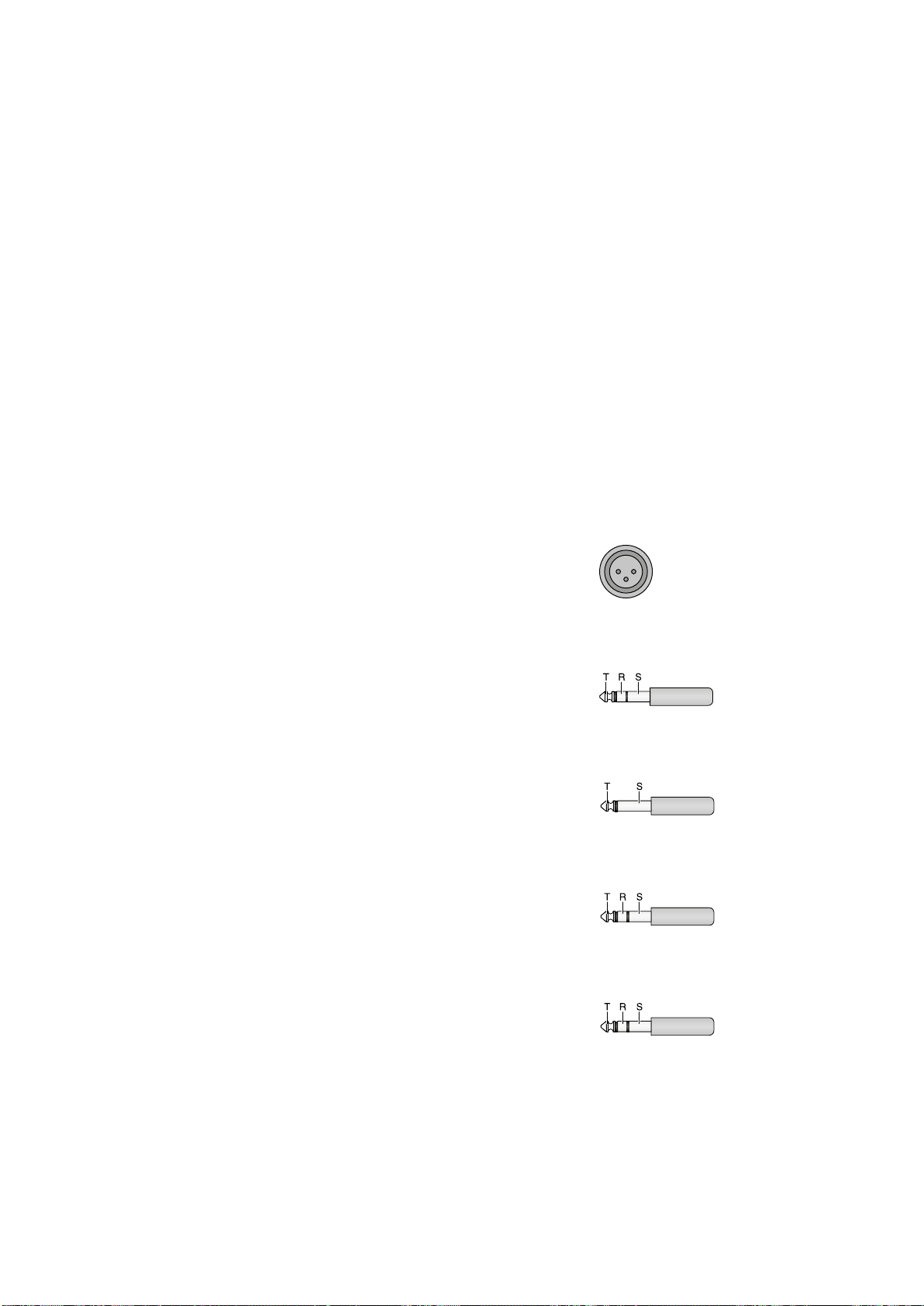
5.5.3 Separate effect unit for the subgroups
Independently of the options described in chapters 5.5.1 and 5.5.2, the signals of the subgroups can be routed via a separate effect unit.
1) Connect the input of the effect unit to the
jacks SUB OUT (54) and connect the output
of the effect unit to an available line input
of the mixer.
2) Use the buttons ASSIGN TO MASTER (26) to
select one of the following options:
− To route the signals of the subgroups
entirely via the effect unit and to add them
to the sum channels from there, disengage
all buttons.
− To add the signals of the subgroups to the
sum channels in the mixer and to add the
effect signals of the subgroups to the sum
channels, press the appropriate buttons
(usually, the button L in channel SUB 1 and
the button R in channel SUB 2).
3)
Use the faders SUB 1 and 2 (24) to adjust the
level with which the signals of the subgroups
are fed to the effect unit and, if applicable,
to the sum channels.
4) Make all the other adjustments at the effect
unit and at the input channel to which the
effect unit is connected.
5.6 Monitoring via headphones
and a control monitor system
For monitoring via headphones connected to
the jack PHONES (52) and via a control monitor
system connected to the jacks BOOTH OUT (53),
the following signals can be selected:
1. the signal of each input channel
2. the total signals of send ways 1 and 2
3.
the input signals of the jacks TAPE IN (23)
and of the USB port (45)
4. the signals of subgroups 1 and 2 at the outputs SUB OUT (54)
5. the sum signals of the mixer at the outputs
MASTER (50)
The level indicators (38) always indicate the
level of the signals that have been selected for
monitoring.
1)
To monitor an input channel, press the
button SOLO (2) of the channel. The LED
PEAK (5) lights up to indicate that the monitor function for the channel has been activated. Additionally, the LED beneath the
button PFL/AFL (40) lights up: green for the
monitor mode “PFL” or red for the mode
“AFL”.
− When the button PFL/ AFL is disengaged,
the mode “PFL” (pre-fader listening) is activated. This mode can be used to adjust
the level of a channel: The channel signal
is monitored and indicated (mono) ahead
of the fader (1) and the panorama control
(7) or balance control (8).
− When the button PFL /AFL is engaged,
the mode “AFL” (after-fader listening) is
activated with which the overall channel
adjustment can be checked: The channel
signal is monitored and indicated (stereo)
after the fader and the panorama control
or balance control.
2)
To monitor a send way, press the corresponding button SOLO (29):
for send way 1, the button SOLO next to the
control AUX SEND MASTER 1 (30),
for send way 2, the button SOLO next to the
control AUX SEND MASTER 2 (28).
Use the button PFL /AFL to select the monitor mode: When the button is disengaged,
the signal will be monitored and indicated
ahead of the control AUX SEND MASTER;
when the button is engaged, the signal will
be monitored and indicated after the control
AUX SEND MASTER.
3)
To monitor the input signal of the jacks TAPE
IN (23) und of the USB port (45), e. g. to
check a recording, press the button CD / USB /
TAPE(32).
4)
To monitor the subgroup signals (always
post-fader), press the button SUB 1-2 (32).
5) To monitor of the sum signals (always postfader), press the button MASTER MIX (32).
Important: The buttons SOLO (2, 29) take priority over the buttons BOOTH (32), i. e. when
at least one button SOLO is engaged, the signals selected by means of the buttons BOOTH
will not be monitored / indicated. The buttons
BOOTH, however, have the same priority, i. e.
when they are all engaged, the mixed signal of
the corresponding sources will be monitored
and indicated.
6 Specifications
Inputs
(sensitivity/ impedance; connection)
Mic: � � � � � � � � � � � � � � � 0�5 mV/1�8 kΩ;
XLR, balanced
Line (mono channel): � � 1 mV/10 kΩ;
6�3 mm jack, bal�
Line (stereo channel): � � 10 mV/10 kΩ;
6�3 mm jack, bal�
Tape In: � � � � � � � � � � � � 100 mV/10 kΩ; RCA
Return: � � � � � � � � � � � � 100 mV/10 kΩ;
6�3 mm jack, unbal�
Insert: � � � � � � � � � � � � � 100 mV/10 kΩ;
6�3 mm jack, unbal�
Output level
Master
XLR jacks: � � � � � � � � � 1�5 V*
6�3 mm jacks: � � � � � � 750 mV*
Tape Out: � � � � � � � � � � � 750 mV*
Booth Out: � � � � � � � � � � 2 V*
*at indication 0 dB
Aux Send: � � � � � � � � � � 9�5 V max�
Headphone impedance: � � � ≥ 8 Ω
USB interface: � � � � � � � � � � USB 2�0 (full speed)
Frequency range: � � � � � � � � 20 – 20 000 Hz
THD: � � � � � � � � � � � � � � � � � < 0�05 %
S / N ratio: � � � � � � � � � � � � � > 74 dB (A weighted)
Crosstalk: � � � � � � � � � � � � � −63 dB
Equalizer controls
bass frequencies: � � � � � ±15 dB / 80 Hz
high frequencies: � � � � � ±15 dB / 12 kHz
mid-frequencies
mono channel: � � � � � � ±15 dB / 100 – 8000 Hz
mid-frequencies
stereo channel: � � � � � � ±15 dB / 500 Hz
±15 dB / 3000 Hz
Low cut filter: � � � � � � � � � � 75 Hz
Phantom power: � � � � � � � � +48 V
Power supply:
� � � � � � � � � � 230 V/ 50 Hz
Power consumption: � � � � � 40 VA max�
Ambient temperature: � � � � 0 – 40 °C
Dimensions (W × H × D): � 404 × 96 × 385 mm
Weight: � � � � � � � � � � � � � � � 5�2 kg
Suitable operating systems for data transfer via the
USB interface:
Windows 2000, Windows XP or subsequent
Windows versions
Mac OS 9.0.4 or later, Mac OS X
Windows is a registered trademark of Microsoft Corporation in the
USA and other countries.
Mac OS is a registered trademark of Apple Inc. in the USA and
other countries.
6.1 Pin configuration of XLR and
6.3 mm plugs
XLR plug for balanced connection
1 = ground
2 1
3
2 = signal +
3 = signal −
3-pole 6.3 mm plug
for balanced connection
T = signal +
R = signal −
S = ground
2-pole 6.3 mm plug
for unbalanced connection
T = signal
S = ground
3-pole 6.3 mm plug
for the INSERT jacks
T = Send (output))
R = Return (input))
S = ground
6.3 mm stereo plug
for the headphone connection
T = left channel
R = right channel
S = ground
Subject to technical modification.
English
All rights reserved by MONACOR ® INTERNATIONAL GmbH & Co. KG. No part of this instruction manual
may be reproduced in any form or by any means for any commercial use.
15

Table de mixage audio
Cette notice s’adresse aux utilisateurs avec des
connaissances techniques de base en audio.
Veuillez lire la présente notice avec attention
Français
avant le fonctionnement et conservez-la pour
pouvoir vous y reporter ultérieurement.
Vous trouverez sur la page 3, dépliable, les
éléments et branchements décrits.
Table des matières
1 Eléments et branchements . . . . . 16
1.1 Canaux d’entrée. . . . . . . . . . . 16
1.2 Panneau de sortie . . . . . . . . . . 16
1.3 Face arrière . . . . . . . . . . . . . 17
2 Conseils d’utilisation
etdesécurité
3 Possibilités d’utilisation . . . . . . . 17
4 Branchements . . . . . . . . . . . . . 18
4.1 Sources audio . . . . . . . . . . . . 18
4.1.1 Microphones . . . . . . . . . . . . 18
4.1.2 Sources audio ligne . . . . . . . . . 18
4.2 Appareils à effets . . . . . . . . . . 18
4.2.1 Insertion d’appareils à effets . . . . 18
4.2.2 Utilisation des voies . . . . . . . . . 18
4.3 Enregistreur . . . . . . . . . . . . . 18
4.4 Branchement d’une installation
moniteur de régie et casque . . . . . 18
4.5 Installation moniteur
pour les musiciens . . . . . . . . . . 18
4.6 Amplificateur pour
la sonorisation d’une salle
4.7 Fonctionnement avec unordinateur . 18
4.8 Sorties pour les sous-groupes . . . . 19
4.9 Pédale pour le processeur d’effets . . 19
4.10 Alimentation . . . . . . . . . . . . 19
5 Utilisation . . . . . . . . . . . . . . . . 19
5.1 Marche / Arrêt . . . . . . . . . . . . 19
5.2 Gestion des canaux d’entrée. . . . . 19
5.3 Mixage des signaux d’entrée . . . . 19
5.4 Réglage de la voie moniteur . . . . . 20
5.5 Mixage des effets . . . . . . . . . . 20
5.5.1 Processeur interne d’effets . . . . . 20
5.5.2 Appareil externe à effets . . . . . . 20
5.5.3 Appareil d’effets séparé
pour les sous-groupes
5.6 Ecoute via un casque ou une
installation moniteur de régie
6 Caractéristiques techniques. . . . . 21
6.1 Configuration des fiches XLR et jack . 21
. . . . . . . . . . . . . . 17
. . . . . . 18
. . . . . . . 21
. . . . 21
1 Eléments et branchements
1.1 Canaux d’entrée
Schéma 1 Canal d’entrée mono CH 1 ; les autres
canaux d’entrée mono sont identiques
Schéma 2 Canal d’entrée stéréo CH 9 / 10 ; le
second canal d’entrée stéréo est identique à
l’exception de la position 19.
1 Fader de canal pour le volume du canal et
pour le fondu-enchaîné du signal du canal
2
Touche SOLO pour écouter le canal sélectionné via un casque relié à la prise PHONES
(52) et via une installation moniteur reliée
aux prises BOOTH OUT (53) :
soit pour la préécoute si la touche PFL /
AFL (40) n’est pas enfoncée
soit pour contrôler le réglage général du
canal après le fader du canal si la touche
PFL /AFL est enfoncée
Si la touche SOLO est enfoncée, la LED PEAK
(5) correspondante brille en continu et le
VU-mètre (38) indique le signal de canal
correspondant.
3
Touche L-R : si la touche est enfoncée, le
signal du canal est mixé sur les canaux
MASTER. Avec le réglage PAN (7) ou BAL
(8), le signal ne peut être mixé que sur le
canal droit ou sur le canal gauche ou sur
les deux canaux.
4
Touche 1-2 : si la touche est enfoncée, le
signal du canal est mixé sur les sous-groupes
SUB 1 et SUB 2. Avec le réglage PAN (7) ou
BAL (8), le signal ne peut être mixé que sur
le groupe SUB 1 ou le groupe SUB 2 ou sur
les deux groupes.
5 LED PEAK : si la touche SOLO (2) est enfon-
cée, la LED brille en continu. Si la touche
SOLO n’est pas enfoncée, elle brille briè
vement indiquant que le niveau de signal
maximal non distordu est atteint. Si elle brille
plus longtemps, le canal est en surcharge.
Tournez alors le réglage GAIN (20) en conséquence vers la gauche.
6
Touche MUTE avec LED de contrôle pour
couper le son du canal
7 Réglage de panoramique PAN pour placer
le signal mono dans l’image sonore stéréo
Si la touche 1-2 (4) est enfoncée, le réglage
sert pour attribuer le signal du canal aux
sous-groupes.
8 Réglage de balance
Si la touche 1-2 (4) est enfoncée, le réglage
sert pour attribuer le signal du canal aux
sous-groupes.
9 Réglage AUX SEND 2 / FX pour mixer le si-
gnal du canal sur la voie 2 (post-fader) ; cette
voie sert simultanément de voie d’effet pour
le processeur interne d’effets
10 Touche de commutation PRE pour la voie 1
non enfoncée : le signal est pris post-fader
Le signal du canal est appliqué sur la voie
après le fader (1).
enfoncée : le signal est pris pre-fader
Le signal est appliqué sur la voie avant le
fader.
11 Réglage AUX SEND 1 / MON pour mixer le
signal de canal sur la voie 1
12 Egaliseur LOW 80 Hz pour les graves :
±15 dB à 80 Hz
13 Egaliseur MID pour les médiums :
±15 dB à 100 Hz – 8 kHz
14
Egaliseur MID 500 Hz pour les médiums à
500 Hz : ±15 dB
15 Réglage MID FREQ pour régler la fréquence
du filtre (100 Hz – 8 kHz) pour le réglage de
tonalité dans la plage des médiums
16
Egaliseur MID 3 kHz pour les médiums à
3 kHz : ±15 dB
17 Egaliseur HIGH 12 kHz pour les aigus :
±15 dB à 12 kHz
18
Touche pour le filtre Low Cut (passe-haut)
Si la touche est enfoncée, les parts de signal
non souhaités sous 75 Hz sont éliminées, par
exemple bruit de pas.
19 Canal CH 9 /10 :
touche +4 /−10 pour adapter le niveau pour
des appareils avec niveau de sortie faible : si
la touche est enfoncée, le niveau d’entrée
est augmenté
canal CH 11/12 :
touche LINE / OPT pour commuter l’entrée
du canal
non enfoncée : entrée = prises LINE (21)
enfoncée : entrée = signal d’un module sup plémentaire (par exemple lecteur MP3)
inséré en haut à droite à la place du cache
20
Réglage GAIN pour régler l’amplification
d’entrée
21 Entrée LINE (jack 6,35, sym) pour brancher
une source de signal avec niveau de sortie
ligne (par exemple instrument de musique,
lecteur CD / MP3)
Conseil pour les canaux stéréo : si vous bran-
chez un appareil mono, utilisez uniquement la
prise L. Le signal est dirigé en interne sur le canal
droit et sur le canal gauche.
22 Entrée MIC pour brancher un microphone
(prise XLR, sym)
-
Pour toutes les entrées micro, on peut
commuter l’alimentation fantôme, ☞position49.
23 Prises d’entrée et de sortie (RCA) TAPE pour
un enregistreur
Le signal master est présent aux prises OUT
[après les faders MASTER (34)].
Le signal des prises IN est mixé sur le signal
master avant les faders MASTER si la touche
TAPE / USB TO MIX (41) est enfoncée.
1.2 Panneau de sortie
24 Faders pour les sous-groupes SUB 1 et 2
25
Touches MUTE avec LED de contrôle pour
couper le son des sous-groupes
26
Touches d’attribution SUB ASSIGN TO MASTER pour diriger les signaux des sous-groupes
sur le canal master gauche ou / et droit
27
Réglage de niveau FX RETURN pour le signal d’effet du processeur interne d’effets
ou pour le signal à l’entrée FX RETURN (57)
Le signal est mixé avec le réglage sur les
canaux MASTER.
28 Réglage de niveau AUX SEND MASTER 2 /
FX pour le signal total de la voie 2, qui est
appliqué au processeur interne d’effets et à
la sortie AUX SEND 2 (55)
29 Touche SOLO – respectivement pour la voie
1 et 2 – pour écouter la voie via un casque
relié à la prise PHONES (52) et via une installation moniteur reliée aux prises BOOTH
OUT (53)
30 Réglage de niveau AUX SEND MASTER 1 /
MON pour le signal total de la voie 1, disponible à la sortie AUX SEND 1 (55)
16

31 Réglage de niveau AUX RTN pour mixer les
signaux à l’entrée AUX RTN (56) sur les canaux MASTER [touche MASTER / SUB 1-2
(39) non enfoncée] ou sur les canaux des
sous-groupes [touche enfoncée]
32
Touches BOOTH pour sélectionner les signaux écoutés via la sortie casque PHONES
(52) et la sortie BOOTH OUT (53) et devant
être indiqués sur le VU-mètre (38) :
– touche MASTER MIX pour les signaux de
sortie des canaux MASTER
– touche CD / USB / TAPE pour les signaux
d’entrée des prises TAPE IN (23) et du
port USB (45)
– touche SUB 1-2 pour les signaux des sous-
groupes 1 et 2
Remarque :
1. Si plusieurs touches sont enfoncées, le signal
de mixage des sources correspondantes est
écouté et indiqué.
2. Les signaux sélectionnés avec les touches
SOLO (2, 29) ont priorité : si une touche SOLO
est enfoncée, les signaux correspondants sont
écoutés et indiqués et pas les signaux sélectionnés avec les touches BOOTH.
33
Réglage de volume BOOTH / PHONES pour
la sortie casque PHONES (52) et la sortie
BOOTH OUT (53)
34 Fader pour les canaux master
35
LED PHANTOM 48 V : brille lorsque l’alimentation fantôme est activée pour les entrées
MIC (22)
36 Témoin de fonctionnement POWER ON
37 Réglage RETURN TO AUX 1 pour mixer les
signaux du processeur interne d’effets ou les
signaux des prises FX RTN (57) sur la voie 1
38 VU-mètre ; indique le niveau du signal sé-
lectionné pour l’écoute via la sortie casque
PHONES (52) et la sortie BOOTH OUT (53) :
– les signaux des canaux d’entrée / voies dont
la touche SOLO (2, 29) est enfoncée
– si aucune touche SOLO n’est enfoncée, le
signal d’écoute sélectionné avec la touche
BOOTH (32)
39
Touche d’attribution MASTER / SUB 1-2 pour
diriger les signaux de l’entrée AUX RTN (56)
sur les canaux MASTER (touche non enfoncée) ou sur les canaux des sous-groupes
(touche enfoncée)
40 Touche PFL /AFL avec LED de contrôle des-
sous :
touche non enfoncée = PFL
(pre fader listening)
Les canaux d’entrée pour lesquels la
touche SOLO (2) est enfoncée, sont écoutés avant le réglage PAN (7) ou BAL (8)
et avant le fader (1) et les voies pour lesquelles la touche SOLO (29) est enfoncée,
avant le réglage AUX SEND (28, 30).
touche enfoncée = AFL (after fader listening)
Les canaux d’entrée pour lesquels la
touche SOLO est enfoncée, sont écoutés
après le réglage PAN ou BAL et après le
fader, et les voies pour lesquelles la touche
SOLO est enfoncée après le réglage AUX
SEND.
41 Touche TAPE / USB TO MIX : si la touche est
enfoncée, les signaux d’entrée des prises
TAPE IN (23) et du port USB (45) sont dirigés
vers les canaux MASTER.
42 Touche MUTE pour activer et désactiver un
effet sélectionné
La LED PEAK au-dessus de la touche brille
en continu, si l’effet est désactivé.
Elle ne brille qu’en cas de surcharge du processeur d’effet si l’effet est activé.
43 Bouton FX SELECT pour la sélection de l’ef-
fet: tournez le bouton jusqu’à ce que sur
l’affichage (44), le numéro de l’effet soit affiché en clignotant puis appuyez brièvement
sur le bouton pour confirmer.
44 Affichage EFFECT pour indiquer le numéro
de l’effet sélectionné
45 Port USB (type B) pour une connexion
avec un ordinateur : peut simultanément
sertir de sortie (émission digitale du signal
master) et comme entrée (entrée de données audio (fonctionnement Full Duplex)
1.3 Face arrière
46
Prise secteur pour brancher à une prise
230 V/ 50 Hz via le cordon secteur livré
47 Porte-fusible
Tout fusible fondu doit être remplacé impérativement par un fusible de même type.
48 Interrupteur POWER
49
Interrupteur PHANTOM de l’alimentation
fantôme 48 V pour toutes les entrées micro
MIC (22) ; lorsque l’alimentation fantôme
est activée, la LED PHANTOM 48 V (35) brille
Reportez-vous aux instructions relatives à
l’alimentation fantôme, chapitre 4.1.1
50
Sorties MASTER pour le signal master par
exemple pour brancher l’amplificateur pour
une sonorisation de salle
– via prises XLR,
gauche L / droite R, symétrique
– via prises jack 6,35,
gauche L / droite R, asymétrique
51
Branchement FOOT SWITCH (prise jack
6,35, 2 pôles) pour une pédale pour allumer / éteindre le processeur interne d’effets
52 Sortie PHONES (prise jack 6,35) pour bran-
cher un casque stéréo (impédance minimale
8 Ω)
53 Sortie BOOTH OUT (prises jack 6,35 gauche
L / droite R, asym) pour brancher une installation moniteur de régie
54
Sorties SUB OUT (prises jack 6,35, asym)
pour les sous-groupes 1 et 2
55 Sorties AUX SEND (prises jack 6,35, asym)
pour les voies 1 et 2
56
Entrées AUX RTN (prises jack 6,35 gauche L /
droite R, asym), peut être utilisée comme
entrée pour un appareil à effets ou pour une
source audio ligne supplémentaire.
Conseil : Si on branche un appareil mono, uti-
lisez uniquement la prise L. Le signal est dirigé
en interne sur le canal gauche et le canal droit.
57
Entrées signal d’effet FX RTN (prise jack 6,35
gauche L / droite R, asym)
Lorsque les entrées sont branchées, le signal
d’entrée est dirigé vers les canaux master, la
voie de signal du processeur interne d’effets
vers les canaux master est interrompue.
58 Prises CHANNEL INSERTS (prises jack 6,35)
pour insérer des appareils à effets (par
exemple compresseurs) dans les canaux
d’entrée mono CH 1 à CH 8
branchements :
pointe = Send (sortie)
anneau = Return (entrée)
corps = masse
2 Conseils d’utilisation
etdesécurité
L’appareil répond à toutes les directives nécessaires de l’Union européenne et porte donc le
symbole
AVERTISSEMENT
L’appareil n’est conçu que pour une utilisation
•
en intérieur. Protégez-le des éclaboussures, de
tout type de projections d’eau, d’une humidité d’air élevée et de la chaleur (température
ambiante admissible 0 – 40 °C).
En aucun cas, vous ne devez pas poser d’objet
•
contenant du liquide ou un verre sur l’appareil.
Ne faites pas fonctionner l’appareil et débran-
•
chez le cordon secteur immédiatement dans
les cas suivants :
1.
2.
3. des dysfonctionnements apparaissent.
Dans tous les cas, les dommages doivent être
réparés par un technicien spécialisé.
Ne débranchez jamais l’appareil en tirant sur
•
le cordon secteur ; retirez toujours le cordon
secteur en tirant la fiche.
Pour le nettoyage, utilisez uniquement un
•
chiffon sec et doux, en aucun cas de produits
chimiques ou d’eau.
Nous déclinons toute responsabilité en cas de
•
dommages corporels ou matériels résultants
si l’appareil est utilisé dans un but autre que
celui pour lequel il a été conçu, s’il n’est pas
correctement branché ou utilisé ou s’il n’est
pas réparé par une personne habilitée ; en
outre, la garantie deviendrait caduque.
.
L'appareil est alimenté par
une tension dangereuse. Ne
touchez jamais l'intérieur
de l'appareil et ne faites
rien tomber dans les ouïes
de ventilation car, en cas de
mauvaise manipulation, vous
pouvez subir une décharge
électrique.
l’appareil ou le cordon secteur présente des
dommages visibles.
après une chute ou accident similaire, vous
avez un doute sur l’état de l’appareil.
Lorsque l'appareil est définitivement retiré du service, vous devez le déposer
dans une usine de recyclage de proximité pour contribuer à son élimination
non polluante.
CARTONS ET EMBALLAGE
PAPIER À TRIER
3 Possibilités d’utilisation
Cette table de mixage audio est adaptée pour
des applications de sonorisation et enregistrement. Elle dispose de 8 canaux d’entrée mono
et de 2 canaux d’entrée stéréo pour brancher
des microphones (également à alimentation fantôme) et des sources audio avec niveau de sortie
ligne (par exemple instruments, lecteurs). Les
signaux d’entrée peuvent être mixés sur un canal
master stéréo, deux sous-groupes et deux voies.
Le processeur d’effets intégré peut être utilisé
pour mixer les effets. Le mixage audio peut
être écouté via un casque et / ou une installation
moniteur dans une pièce de régie distincte.
En plus des branchements RCA pour un
enregistreur, la table de mixage possède une
interface audio USB pour une connexion à un
Français
17

ordinateur. Elle peut être utilisée aussi bien
RETURN SEND
comme sortie pour un enregistrement digital du
mixage audio que comme entrée pour alimenter
des données audio.
Français
4 Branchements
Pour éviter tout bruit fort de commutation, avant
d’effectuer les branchements des appareils ou de
modifier les branchements existants, éteignez la
table de mixage ou tournez les réglages suivants
entièrement vers la gauche / fermez les faders
suivants :
− MASTER (34)
− BOOTH /PHONES (33)
− AUX SEND MASTER 1 / MON (30) si la voie 1
est utilisée comme voie moniteur.
4.1 Sources audio
Etant donné que l’on ne peut pas commuter
entre les entrées dans les canaux mono, utilisez
soit l’entrée micro (22) soit l’entrée ligne (21),
pas les deux en même temps.
4.1.1 Microphones
Branchez des microphones aux prises XLR MIC
(22) branchées en symétrique. Pour des microphones à alimentation fantôme, on peut activer
une alimentation fantôme 48 V ensemble pour
toutes les prises XLR avec l’interrupteur PHANTOM (49) sur la face arrière. Lorsque l’alimentation fantôme est activée, la LED PHANTOM 48 V
(35) brille pendant le fonctionnement.
Attention : Des microphones avec sortie asymétrique ne doivent pas être branchés si l'alimentation fantôme est activée, ils pourraient
être endommagés.
Pour éviter tout bruit fort de commutation dans
les enceintes et le casque, allumez ou éteignez
l’alimentation fantôme uniquement lorsque la
table de mixage est éteinte ou si les réglages des
sorties sont entièrement tournés vers la gauche.
4.1.2 Sources audio ligne
Reliez des appareils avec niveau de sortie ligne
(par exemple récepteurs de systèmes de micros
sans fil, appareils à effets, instruments, lecteurs)
aux prises jack 6,35 LINE (21) des canaux d’entrée. Les prises sont branchées en symétrique.
On peut également brancher des appareils avec
sortie asymétrique via des fiches jack 2 pôles.
− Reliez les appareils mono aux canaux mono
CH 1 et CH 8.
− Reliez les appareils stéréo aux canaux stéréo
CH 9 /10 et CH 11/12. Si un appareil mono doit
être relié à un canal stéréo, utilisez uniquement la prise L. Le signal mono est alors dirigé
en interne sur le canal gauche et le canal droit.
Si les canaux d’entrée ne suffisent pas, on peut
utiliser également les entrées stéréo suivantes
pour brancher des sources ligne supplémentaires :
1. entrée AUX RTN (56)
(Si vous brancher un appareil mono, utilisez
uniquement la prise L, le signal mono est
alors dirigé en interne sur le canal gauche et
le canal droit).
2. entrée FX RTN (57)
(Si vous utilisez cette entrée, la voie du processeur d’effets interne vers les canaux master est interrompue.)
3. entrée TAPE IN (23)
(p. ex. pour brancher un lecteur CD pour
une musique d’ambiance dans les pauses
de musique)
4.2 Appareils à effets
4.2.1 Insertion d’appareils à effets
On peut insérer des appareils à effets (par
exemple appareils pour le traitement du son
tels que compresseur, égaliseur, noise gate)
directement dans les canaux mono : le signal du
canal est découplé après le réglage GAIN (20) et
le filtre Low Cut (18), il traverse complètement
l’appareil à effets et est redirigé au même endroit
de la voie de signal dans la voie du canal.
Reliez l’appareil à effets à la prise jack 6,35
CHANNEL INSERT (58) du canal correspondant.
Les fiches doivent être branchées comme suit :
pointe = Send (sortie)
anneau = Return (entrée)
corps = masse
Pour brancher des appareils à effets avec
prises d’entrée et sortie séparées, des cordons
Y sont nécessaires, par exemple MCA-202 de
MONACOR :
noir
rouge
noir
Schéma 6 Branchement du cordon Y MCA-202
SEND
RETURN
signal
signal
signal
entrée
appareil à effects
sortie
appareil à effects
prise
INSERT
4.2.2 Utilisation des voies
Via les voies 1 et 2, on peut découpler des parts
de signal aux canaux d’entrée via un appareil à
effets (par exemple appareil d’écho) et les faire
revenir dans la table de mixage via les entrées
Return. Le signal pour une voie utilisée comme
voie d’effet est pris par habitude en post-fader,
c’est-à-dire que le signal est mixé sur la sortie
après le fader (1). Ainsi, la part de signal d’un
canal est toujours proportionnelle au niveau
réglé du canal. La voie 1 est commutable pour
chaque canal de post-fader sur pre-fader, en
appuyant sur la touche PRE (10). La voie 2 est
réglée de manière fixe sur post-fader. Elle sert
simultanément de voie d’effet pour le processeur
interne d’effets.
1)
Selon la voie utilisée, reliez l’entrée de l’appareil à effets via une fiche jack 6,35 à la sortie
mono AUX SEND 1 ou 2 (55).
2)
Pour le retour du signal venant de l’appareil à effets, les entrées AUX RTN (56) et FX
RTN(57) sont disponibles :
− Si vous utilisez l’entrée AUX RTN, le signal d’effet peut être mixé avec le réglage
AUX RTN (31) soit sur les canaux MASTER
[touche MASTER / SUB 1-2 (39) non enfoncée] soit sur les canaux de sous-groupes
[touche MASTER / SUB 1-2 enfoncée].
Conseil : Si vous branchez un appareil mono,
utilisez uniquement la prise L. Le signal est alors
dirigé en interne sur le canal gauche et le canal
droit.
− Si vous utilisez l’entrée FX RTN, le signal
d’effet se mixe avec le réglage FX RETURN
(27) sur les canaux master et avec le réglage RETURN TO AUX 1 (37) sur la voie 1.
Conseil : Le branchement de la prise L et R de
cette entrée interrompt respectivement la voie
de signal du canal gauche et du canal droit
du processeur interne d’effets vers les canaux
master.
A la place, les signaux de l’appareil à effets
peuvent également être appliqués sur l’entrée ligne d’un canal d’entrée libre.
4.3 Enregistreur
On peut relier un enregistreur aux prises RCA
TAPE (23) [L = canal gauche, R = canal droit] :
1) Pour la lecture, reliez la sortie de l’appareil
aux prises TAPE IN.
2)
Pour l’enregistrement, reliez l’entrée de
l’enregistreur aux prises TAPE OUT. Le signal
master réglé avec les faders MASTER (34)
est présent ici.
4.4 Branchement d’une installation
moniteur de régie et casque
On peut écouter, via un casque stéréo et / ou
via une installation moniteur dans une pièce de
régie distincte, les signaux des canaux d’entrée
individuels, les signaux master, les signaux des
sous-groupes et les signaux d’entrée des prises
TAPE IN (23) et du port USB (45). Reliez le casque
(impédance minimale 8 Ω) à la prise PHONES
(52). Reliez l’amplificateur de l’installation moniteur aux prises BOOTH OUT (53) ; ces prises de
sortie sont branchées en asymétrique.
4.5 Installation moniteur
pour les musiciens
Si vous utilisez une installation moniteur pour la
sonorisation de scène, on peut utiliser la voie 1
comme voie moniteur. Le signal pour une voie
utilisée comme voie moniteur est pris par habitude en pre-fader, c’est-à-dire que le signal du
canal est mixé sur la voie avant le fader (1). Ainsi,
les musiciens obtiennent un signal de musique
mixé séparément via les moniteurs de scène.
La voie 1 peut être commutée sur pre-fader, en
appuyant sur les touches PRE (10) pour chaque
canal d’entrée.
Reliez l’amplificateur de l’installation moniteur ou une enceinte moniteur active à la prise
de sortie mono AUX SEND 1 (55).
4.6 Amplificateur pour
la sonorisation d’une salle
Le signal master stéréo est disponible aux sorties
MASTER (50) :
1. Prises XLR branchées en symétrique
2. Prises jack 6,35 branchées en asymétrique
(L = canal gauche, R = canal droit)
L’amplificateur peut être relié à une des sorties
pour la sonorisation de salle. La seconde peut
être utilisée simultanément par exemple pour
un second amplificateur ou pour diriger le signal
master sur un appareil supplémentaire.
4.7 Fonctionnement avec
unordinateur
On peut transmettre via le port USB (45) des
données audio, dans les deux sens, entre la table
de mixage et l’ordinateur :
− utilisation comme entrée : on peut commuter,
avec la touche TAPE / USB TO MIX (41), sur le
signal master les données venant via le port
USB (45) et les écouter via le casque / installation moniteur de régie.
− utilisation comme sortie : le port USB met
à disposition le signal master réglé avec les
faders MASTER (34).
Pour faire fonctionner la table de mixage avec
un ordinateur, on peut utiliser le logiciel audio
livré avec le système d’exploitation ou un logiciel
audio installé en plus. Différents programmes
audio pour l’enregistrement et la lecture sont
disponibles gratuitement sur Internet.
18

1)
Faites monter l’ordinateur et reliez le port
USB (45) de la table de mixage à un port USB
de l’ordinateur.
2)
La table de mixage allumée est reconnue par
l’ordinateur comme appareil audio USB pour
l’entrée et la sortie audio. Les drivers nécessaires (drivers standard du système d’exploitation) devraient être prévus sur l’ordinateur.
Remarque : Si tous les drivers nécessaires ne sont
pas présents sur l’ordinateur, vous devez les installer, par exemple via le CD d’origine du système
d’exploitation. Si besoin, redémarrez l’ordinateur
après l’installation.
3)
Appelez le programme audio utilisé et effectuez les réglages nécessaires pour la lecture
audio via la table de mixage ou l’enregistrement audio depuis la table de mixage
(☞ notice du programme). La table de
mixage peut être utilisée selon le chapitre 5.
S’il n’y a pas d’enregistrement audio ou de lecture audio, vérifiez dans les réglages système de
l’ordinateur si l’interface USB est sélectionnée
pour la lecture audio ou la sortie audio.
Remarque : Si la table de mixage est reliée à un
ordinateur et à des appareils mis à la terre (p. ex.
amplificateur) via leur cordon secteur, des ronflements causés par des bouclages de masse peuvent
se produire. Pour les supprimer, on peut relier la table
de mixage à l’appareil correspondant via un filtre
séparateur galvanique (p. ex. FGA-102 ou FGA-202).
4.8 Sorties pour les sous-groupes
Les signaux des sous-groupes peuvent être commutés avec les touches SUB ASSIGN TO MASTER
(26) sur le signal master et sont simultanément
disponibles aux sorties SUB OUT (54). On peut
les diriger, à partir de ces sorties, par exemple
sur une autre table de mixage ou un appareil à
effets distinct.
4.9 Pédale pour le processeur d’effets
Pour allumer et éteindre le processeur interne
d’effets, on peut relier une pédale, par exemple
FS-60 de MONACOR, à la prise jack 6,35 femelle
2 pôles FOOT SWITCH (51).
4.10 Alimentation
Reliez la table de mixage via la prise secteur (46)
au cordon secteur livré et à une prise secteur
230 V/ 50 Hz.
5 Utilisation
ATTENTION
troubles de l'audition. L'oreille s'habitue à des
volumes élevés et ne les perçoit plus comme
tels au bout d'un certain temps. Nous vous
conseillons donc de régler le volume et de ne
plus le modifier.
5.1 Marche / Arrêt
1) Pour éviter tout bruit fort à l’allumage et un
volume trop élevé, avant d’allumer la table
de mixage, tournez les réglages suivants sur
le minimum :
− MASTER (34)
− BOOTH / PHONES (33)
− AUX SEND MASTER / MON (30) si la voie 1
est utilisée comme voie moniteur.
Ne réglez jamais le volume de
l'installation audio et du casque
trop fort. Un volume trop élevé
peut, à long terme, générer des
2) Selon le type de microphone utilisé, activez
ou désactivez l’alimentation fantôme 48 V
avec l’interrupteur PHANTOM (49) [☞ chapitre
4.1.1].
3) Pour allumer et éteindre la table de mixage,
activez l’interrupteur POWER (48). Lorsque
l’appareil est allumé, la LED POWER ON (36)
brille.
5.2 Gestion des canaux d’entrée
Les étapes suivantes ne servent que d’aide, on
peut procéder différemment.
1)
Effectuez tout d’abord le réglage de base
suivant :
a)
Dans tous les canaux d’entrée mono
(schéma 1), tournez les réglages GAIN (20),
égaliseurs HIGH (17), MID (13), LOW(12)
et les réglages PAN (7) sur le milieu.
Désenclenchez les touches (18).
b)
Dans tous les canaux d’entrée stéréo
(schéma 2), tournez les égaliseurs HIGH
(17), MID 3 kHz (16), MID 500 Hz (14),
LOW (12) et les réglages BAL (8) sur le
milieu. Dans le canal CH 9 /10, désenclen
chez la touche +4 /−10 (19) et dans le
canal CH 11/12, la touche LINE / OPT (19).
c)
Dans tous les canaux d’entrée, tournez
vers le minimum les réglages AUX SEND 1 /
MON (11) et AUX SEND 2 / FX (9) pour
les voies.
d)
Dans tous les canaux d’entrée, désenclenchez les touches MUTE (6), 1-2 (4), L-R
(3) et SOLO (2) et fermez les faders des
canaux (1).
e)
Dans le panneau de sortie (schéma 3),
désenclenchez toutes les touches SOLO
(29) et la touche TAPE / USB TO MIX (41) et
tournez les réglages AUX SEND MASTER
(28, 30) et RETURN (27, 31, 37) vers le
minimum.
2)
Appliquez un signal audio (p. ex. parlez dans
un micro, jouez d’un instrument) sur le premier canal utilisé.
3) Pour écouter le signal audio via l’amplificateur pour la sonorisation d’une salle, poussez
le fader (1) du canal jusque sur la position
«0», appuyez sur la touche L-R (3) et poussez
les faders MASTER (34) jusqu’à ce que le signal soit correctement audible. Le signal peut
être écouté via un casque ou une installation
moniteur de régie même si les faders sont
fermés, ☞ chapitre 5.6.
4) Appuyez sur la touche SOLO (2). La fonction
d’écoute pour le canal est activée ; la LED
PEAK (5) brille.
5)
Si besoin, appuyez sur la touche PFL /AFL (40)
pour sélectionner le mode d’écoute «PFL» :
la LED au-dessus la touche brille en vert et
la rangée gauche de LEDs du VU-mètre (38)
indique le signal de canal avant le fader (1) et
avant le réglage PAN (7) ou BAL (8).
6) Selon les indications du VU-mètre, réglez de
manière optimale l’amplification d’entrée :
Pour un canal mono, réglez le réglage
GAIN (20) de telle sorte qu’un niveau dans
la plage de 0 dB soit indiqué.
Si le canal stéréo CH 9 /10 est en surcharge, même si la touche +4 /−10 (19) est
désenclenchée, il faut diminuer le niveau de
la source de signal. Appuyez sur la touche
+4 /−10 pour augmenter le niveau (12 dB) si
le niveau est trop faible.
Pour le canal stéréo CH 11/12, l’amplification d’entrée est réglée de manière fixe.
Si le réglage n’est pas favorable, modifiez le
niveau de sortie de la source de signal reliée.
7)
Réglez la tonalité avec les réglages HIGH (17)
pour les aigus et LOW (12) pour les graves
(±15 dB).
Pour un canal mono, réglez la fréquence
médiane avec le réglage MID FREQ (15)
(100 – 8000 Hz) et son augmentation ou diminution (15 dB) avec le réglage MID (13). Si
besoin, appuyez sur la touche (18) pour
éliminer les interférences basses fréquences
(par exemple bruits de pas, ronflements).
Pour un canal stéréo, réglez les médiums
avec les réglages MID 500 Hz (14) et MID
3 kHz (16) (±15 dB).
Ensuite vérifiez le réglage du canal et si
besoin, corrigez l’amplification d’entrée.
8)
Désenclenchez la touche SOLO pour désactiver la fonction d’écoute pour le canal.
Lorsqu’elle est éteinte, la LED PEAK sert de
témoin de surcharge permettant de contrôler
le réglage de canal de manière grossière. Si
elle brille en continu, diminuez l’amplification
-
d’entrée (réglage GAIN) ou le signal d’entrée.
9) Pour que lors de la restitution du signal via
l’amplificateur pour la sonorisation d’une
salle, seul le canal qui vient d’être réglé soit
audible, poussez son fader (1) sur le minium
après le réglage ou appuyez sur sa touche
MUTE (6) pour couper le son.
10)
Pour tous les autres canaux d’entrée, répétez
les points 2) à 9).
5.3 Mixage des signaux d’entrée
1)
Pour chaque canal d’entrée, déterminez si
les signaux du canal doivent être mixés sur
les canaux master ou / et sur les canaux des
sous-groupes :
− En appuyant sur la touche L-R (3), les si-
gnaux sont dirigés vers les canaux master
MASTER.
− En appuyant sur la touche 1-2 (4), les si-
gnaux sont dirigés vers les canaux SUB1
et 2. On peut faire un fondu-enchaîné des
signaux ensemble avec les faders SUB 1 et
2 (24) ou modifier le volume et si besoin,
via les prises SUB OUT (53), les diriger vers
un appareil à effets séparé.
2)
Poussez les faders MASTER (34) jusqu’à ce
que le rapport de mixage des sources audio
soit réglé de manière optimale.
3) Mixez les signaux des canaux d’entrée avec
les faders (1) dans le rapport de volume souhaité. Fermez toujours vers le minimum les
faders des canaux inutilisés.
4)
Pour les canaux mono, placez avec les réglages de panoramique PAN (7) les signaux
mono dans l’image sonore stéréo et pour les
canaux stéréo, réglez, avec les réglages BAL
(8), la balance des signaux stéréo.
5)
Si des signaux sont dirigés vers les sousgroupes, appuyez sur les touches correspondantes SUB ASSIGN TO MASTER (26), lorsque
les sous-groupes doivent être mixés sur le
canal master gauche et le canal master droit.
(En règle générale, enfoncez la touche L dans
le canal SUB 1 et la touche R dans le canal
SUB 2). Réglez le volume des signaux des
sous-groupes avec les faders SUB 1 et 2 (24).
6) Pour mixer les effets, voir chapitre 5.5.
7) Pour commuter le signal d’entrée des prises
TAPE IN (23) et du port USB (45) sur le signal
Français
19

master, appuyez sur la touche TAPE / USB TO
MIX (41).
Conseil : Si pendant un enregistrement via les
prises TAPE OUT ou le port USB, le signal d’enre-
Français
gistrement est appliqué comme signal d’entrée
aux prises TAPE IN ou au port USB, la touche
TAPE / USB TO MIX ne doit pas être enfoncée sinon
il y a des effets de larsen.
8)
Avec les faders MASTER, réglez le volume
définitif du signal master en vous aidant du
VU-mètre (38). Pour qu’il affiche le niveau
du signal master, la touche MASTER MIX (32)
doit être enfoncée. Toutes les touches SOLO
(2, 29) pour la fonction d’écoute ne doivent
pas être enfoncées. [Si une des touches SOLO
est enfoncée, la LED sous la touche PFL /AFL
(40) brille]. En cas de surcharge, les LEDs
rouges CLIP du VU-mètre brillent ; fermez
les faders MASTER en conséquence.
9) Pour couper le son d’un canal, par exemple
pendant une pause de lecture, appuyez sur la
touche MUTE (6, 25). La LED sous la touche
sert de témoin de contrôle et brille.
5.4 Réglage de la voie moniteur
L’installation moniteur pour une sonorisation
sur scène doit être reliée à la sortie AUX SEND1
(55) de la voie 1.
1)
Pour les canaux appliqués à la voie moniteur,
appuyez sur la touche PRE (10) pour commuter le point de prise du signal pour la voie
moniteur sur pre-fader.
2)
Tournez le réglage AUX SEND MASTER 1 /
MON (30) pour le volume général du mixage
moniteur jusqu’à ce que le signal moniteur
soit bien audible via l’installation moniteur.
3) Avec les réglages AUX SEND 1 / MON (11),
mixez les canaux des signaux sur la voie moniteur : tournez les réglages selon le rapport
de volume des canaux souhaité.
4) Avec le réglage RETURN TO AUX 1 (37), on
peut mixer le signal d’effet du processeur
interne d’effets sur la voie moniteur 1 ou le
signal des prises FX RTN (57) si un appareil
y est relié.
5) Si la voie moniteur doit être écoutée via un
casque ou une installation moniteur de régie,
et si le VU-mètre (38) doit indiquer le signal
moniteur, appuyez sur la touche SOLO (29)
à côté du réglage AUX SEND MASTER 1 /
MON(30), ☞ chapitre 5.6.
5.5 Mixage des effets
5.5.1 Processeur interne d’effets
Via le processeur interne d’effets, on peut créer
100 effets différents et les mixer sur les canaux
MASTER et la voie 1. La voie 2 sert de voie d’effet
pour le processeur d’effets.
Important : Si le processeur d’effets est utilisé,
l’entrée FX RTN (57) ne doit pas être utilisée.
Si on branche les deux prises, la voie de signal
du processeur interne d’effets vers les canaux
master et la voie 1 est interrompue.
1)
Pour que les réglages d’effets suivants soient
audibles, mettez les réglages AUX SEND
MASTER 2 / FX (28) et FX RETURN (27) sur
la position médiane dans un premier temps.
2)
Tournez le bouton FX SELECT (43) vers la
gauche ou la droite jusqu’à ce que le numéro
de l’effet souhaité (☞ schéma 7 Présentation
effets) clignote sur l’affichage (44). Confirmez la sélection en appuyant sur le bouton :
le numéro ne clignote plus, l’effet est activé.
3)
Avec les réglages AUX SEND 2 / FX (9), mixez
les signaux des canaux d’entrée sur la voie
d’effet. Le signal est pris après le fader (1),
c’est-à-dire que la part d’effet d’un canal est
toujours proportionnelle au niveau de canal
réglé.
4) Avec le réglage AUX SEND MASTER 2 / FX
(28), réglez le niveau de tous les signaux
mixés sur la voie d’effet. Les signaux sont
appliqués à l’entrée du processeur d’effets
et sont présents à la prise AUX SEND 2 (55).
La LED PEAK au-dessus de la touche
MUTE (42) sert de témoin de surcharge
lorsque le processeur d’effets est allumé.
Elle permet de contrôler grossièrement le
réglage. Si elle brille, tournez le réglage AUX
SEND MASTER 2 / FX vers le minimum en
conséquence.
5)
Mixez le signal d’effets avec le réglage FX
RETURN (27) sur les canaux master et si souhaité également sur la voie 1 avec le réglage
RETURN TO AUX 1 (37).
6)
Le processeur d’effets peut être éteint et
allumé avec une pédale reliée à la prise FOOT
SWITCH (51) et avec la touche MUTE (42)
[touche non enfoncée]. S’il est éteint, la LED
PEAK au-dessus de la touche MUTE brille.
5.5.2 Appareil externe à effets
L’appareil à effets doit être relié via une sortie
Aux Send et une entrée Aux Return (ou entrée ligne d’un canal d’entrée libre), ☞ chapitre4.2.2.
1) Pour que les réglages d’effet suivants soient
audibles, réglez le réglage d’entrée et de sortie correspondant tout d’abord sur le milieu
à peu près :
selon la sortie
utilisée
réglage AUX SEND MASTER 1 / MON (30)
ou
réglage AUX SEND MASTER 2 / FX (28)
selon l’entrée utilisée
réglage AUX RTN (31)
ou
réglage FX RETURN (27)
ou
fader (1) du canal d’entrée correspondant
2) Si l’appareil à effets est relié à l’entrée AUX
RTN (56), déterminez avec la touche MASTER / SUB 1-2 (39) si le signal d’effet doit
être dirigé vers les canaux master (touche
non enfoncée) ou vers les canaux des sousgroupes (touche enfoncée).
3)
Selon la voie utilisée comme voie d’effet,
mixez avec les réglages AUX SEND 1 / MON
(11) ou avec les réglages AUX SEND 2 / FX(9),
les signaux des canaux sur la voie d’effet.
Avec ces réglages, on peut régler séparément pour chaque canal l’intensité voulue
de l’effet.
Si la voie 1 est utilisée comme voie d’effet, les touches PRE (10) ne doivent pas être
enfoncées (réglage post-fader).
Remarque : Si l’appareil à effets est relié à une
entrée ligne d’un canal d’entrée, tournez le réglage AUX SEND 1 ou 2 du canal concerné entièrement vers la gauche sinon il y a des effets de
larsen.
4) Avec le réglage de sortie AUX SEND (28, 30)
correspondant, réglez le niveau pour le signal
de sortie de la voie d’effet de telle sorte que
l’appareil à effets ne soit pas en surcharge.
Avec la touche SOLO (29) à côté du réglage AUX SEND, on peut écouter la voie
d’effet ou une installation moniteur de régie
et contrôler via le VU-mètre (38), ☞ chapitre5.6.
5) Mixez le signal venant de l’appareil à effets
avec son réglage d’entrée respectif ; vous
pouvez régler l’intensité de l’effet ensemble
pour tous les canaux :
− si l’appareil à effets est relié à l’entrée AUX
RETURN (56),
mixez le signal d’effet avec le réglage AUX
RTN (31) sur les canaux master ou sur les
canaux des sous-groupes (selon la position
de la touche MASTER / SUB1-2).
− si l’appareil à effets est relié à l’entrée FX
RTN (57),
mixez le signal d’effet avec le réglage FX
RETURN (27) sur les canaux master. En plus,
le signal d’effet peut être mixé avec le réglage RETURN TO AUX 1 (37) sur la voie 1
(par exemple si elle sert de voie moniteur).
− si l’appareil à effets est relié à l’entrée ligne
(21) d’un canal d’entrée,
mixez le signal d’effet avec le fader correspondant (1) sur les canaux master [la
touche L-R (3) doit être enfoncée] et / ou
sur les canaux des sous-groupes [la touche
1-2 (4) doit être enfoncée].
Numéro
00 – 09 VOCAL Effet réverbération, particulièrement adapté pour applications de chant Durée de diminution 0,8 – 0,9 s, durée Pre-Delay 10 – 45 ms
10 – 19 SMALL ROOM Effet réverbération : simulation d’une petite à moyenne pièce Durée de diminution 0,7 – 2,1 s, durée Pre-Delay 20 – 45 ms
20 – 29 LARGE HALL Effet réverbération : simulation d’une grande pièce Durée de diminution 3,6 – 5,4 s, durée Pre-Delay 23 – 55 ms
30 – 39 ECHO Effet Echo Durée Delay 145 – 205 ms
40 – 49 ECHO + VERB Combinaison de l´effet Echo et de l’effet Réverbération Durée Delay 208 – 650 ms, durée de diminution 1,7 – 2,7 s
50 – 59 FLANGE + VERB Combinaison de l’effet Flanger et de l’effet Réverbération Vitesse 0,8 – 2,52 Hz, durée de diminution 1,5 – 2,9 ms
60 – 69 PLATE Simulation d’une réverbération à plaque classique à tonalité claire Durée de diminution 0,9 – 3,6 s
70 – 79 CHORUS + GTR Effet guitare : Chorus Vitesse 0,92 – 1,72 Hz
80 – 89 ROTARY + GTR Effet guitare : Rotary (effet Leslie) Profondeur de modulation 20 – 80 %
90 – 99 TREMOLO + GTR Effet guitare : Tremolo Vitesse 0,6 – 5 Hz
Schéma 7 Présentation effets
Nom Effet Paramètres
20

5.5.3 Appareil d’effets séparé pour les sous-groupes
Indépendamment des possibilités décrites dans
les chapitres 5.5.1 et 5.5.2, on peut diriger les
signaux des sous-groupes via un appareil à effets
séparé.
1)
Reliez l’entrée de l’appareil à effets aux prises
SUB OUT (54) et reliez la sortie de l’appareil
à effets à une entrée ligne libre de la table
de mixage.
2)
Avec les touches SUB ASSIGN TO MASTER
(26), sélectionnez :
− Si les signaux des sous-groupes doivent être
dirigés complètement via l’appareil à effets
puis mixées sur les canaux master, toutes
les touches doivent être désenclenchées.
− Si les signaux des sous-groupes doivent
être mixés dans la table de mixage sur les
canaux master puis les signaux d’effet des
sous-groupes mixés sur les canaux master,
appuyez sur les touches correspondantes
(en règle général dans le canal SUB 1,
la touche L et dans le canal SUB 2, la
toucheR).
3)
Avec les faders SUB 1 et 2 (24), réglez le
niveau avec lequel les signaux des sousgroupes sont appliqués sur l’appareil à effets et éventuellement mixés sur les canaux
master.
4)
Effectuez tous les autres réglages sur l’appareil à effets et sur le canal d’entrée auquel
l’appareil à effets est relié.
5.6 Ecoute via un casque ou une installation moniteur de régie
Pour une écoute via un casque relié à la prise
PHONES (52) et une installation moniteur de
régie aux sorties BOOTH OUT (53), on peut sélectionner les signaux suivants :
1. le signal de chaque canal d’entrée
2. les signaux globaux des voies 1 et 2
3. les signaux d’entrée des prises TAPE IN (23)
et du port USB (45)
4. les signaux des sous-groupes 1 et 2 aux sor-
ties SUB OUT (54)
5.
Les signaux master de la table de mixage aux
sorties MASTER (50)
Le Vu-mètre (38) indique toujours le niveau des
signaux sélectionnés pour l’écoute.
1) Pour une écoute d’un canal d’entrée, ap-
puyez sur la touche SOLO (2) du canal. Pour
indiquer que la fonction écoute est activée
pour le canal, la LED PEAK (5) brille. En plus,
la LED sous la touche PFL /AFL (40) brille : en
vert en mode écoute «PFL» ou en rouge en
mode «AFL».
− Lorsque la touche PFL /AFL n’est pas enfoncée, le mode «PFL» (pre fader listening) est
activé. Il peut être utilisé pour le réglage
de niveau d’un canal : le signal du canal
(mono) est écouté et indiqué avant le fader
(1) et avant les réglages de panoramique
(7) ou de balance (8).
− Si la touche PFL /AFL est enfoncée, le mode
«AFL» (after fader listening) est activé, il
permet de contrôler le réglage général du
canal : le signal du canal (stéréo) est écouté
et indiqué après le fader et après le réglage
de panoramique et de balance.
2)
Pour écouter une voie, appuyez sur la touche
SOLO (29) correspondante :
pour la voie 1, touche SOLO à côté du réglage AUX SEND MASTER 1 (30),
pour la voie 2, touche SOLO à côté du réglage AUX SEND MASTER 2 (28).
Avec la touche PFL /AFL sélectionnez le mode
d’écoute : si la touche n’est pas enfoncée, le
signal est écouté et indiqué avant le réglage
AUX SEND MASTER, si la touche est enfoncée, après le réglage.
3)
Pour écouter le signal d’entrée des prises
TAPE IN (23) et du port USB (45), par exemple
pour contrôler un enregistrement, appuyez
sur la touche CD / USB / TAPE (32).
4)
Pour écouter les signaux des sous-groupes
(toujours post-fader), appuyez sur la touche
SUB 1-2 (32).
5)
Pour écouter les signaux master (toujours
post-fader), appuyez sur la touche MASTER
MIX (32).
Important : Les touches SOLO (2, 29) ont priorité sur les touches BOOTH (32) c’est-à-dire que
si une touche SOLO au moins est enfoncée, tous
les signaux sélectionnés avec les touches BOOTH
ne sont pas écoutés / indiqués. Les touches
BOOTH, en revanche, ont entre elles la même
priorité: si elles sont enfoncées simultanément,
le signal de mixage des sources correspondantes
est en écoute et est indiqué.
6 Caractéristiques techniques
Entrées
(Sensibilité / impédance ; branchement)
Mic : � � � � � � � � � � � � � � 0,5 mV/ 1,8 kΩ ;
XLR, symétrique
Line (canal mono) : � � � 1 mV/ 10 kΩ ;
jack 6,35, sym�
Line (canal stéréo) : � � � 10 mV/ 10 kΩ ;
jack 6,35, sym�
Tape In : � � � � � � � � � � � � 100 mV/ 10 kΩ ; RCA
Return : � � � � � � � � � � � � 100 mV/ 10 kΩ ;
jack 6,35, asym�
Insert : � � � � � � � � � � � � � 100 mV/ 10 kΩ ;
jack 6,35, asym�
Niveau de sortie
Master
Prises XLR : � � � � � � � 1,5 V*
Prises jack : � � � � � � � 750 mV*
Tape Out : � � � � � � � � � � 750 mV*
Booth Out : � � � � � � � � � 2 V*
*pour affichage 0 dB
Aux Send : � � � � � � � � � � max� 9,5 V
Impédance casque : � � � � � � ≥ 8 Ω
Interface USB : � � � � � � � � � USB 2�0 (Full Speed)
Bande passante : � � � � � � � � 20 – 20 000 Hz
Taux de distorsion : � � � � � � < 0,05 %
Rapport signal/bruit : � � � � � > 74 dB (A pondéré)
Atténuation : � � � � � � � � � � � −63 dB
Egaliseur
Graves : � � � � � � � � � � � � ±15 dB / 80 Hz
Aigus : � � � � � � � � � � � � � ±15 dB / 12 kHz
Canal médiums mono : ±15 dB / 100 – 8000 Hz
Canal médiums stéréo : ±15 dB / 500 Hz
±15 dB / 3000 Hz
Filtre Low Cut : � � � � � � � � � 75 Hz
Alimentation fantôme : � � � +48 V
Alimentation :
� � � � � � � � � � 230 V/ 50 Hz
Consommation: � � � � � � � � � max� 40 VA
Température fonc� : � � � � � � 0 – 40 °C
Dimensions (L × H × P) : � � 404 × 96 × 385 mm
Poids : � � � � � � � � � � � � � � � � 5,2 kg
Systèmes d’exploitation adaptés pour le transfert
de données via l’interface USB :
Windows 2000, Windows XP ou
versions Windows ultérieures
Mac OS 9.0.4 ou supérieur, Mac OS X
Windows est une marque déposée de Microsoft Corporation aux
Etats-Unis et dans les autres pays.
Mac OS est une marque déposée de Apple Inc. aux Etats-Unis et
dans les autres pays.
6.1 Configuration des fiches XLR et jack
fiche XLR mâle pour branchement symétrique
1 = Masse
2 1
3
2 = Signal +
3 = Signal −
fiche jack 6,35 mâle 3 pôles
pour branchement symétrique
T = Signal +
R = Signal −
S = Masse
fiche jack 6,35 mâle 2 pôles
pour branchement asymétrique
T = Signal
S = Masse
fiche jack 6,35 mâle 3 pôles
pour les prises INSERT
T = Send (sortie)
R = Return (entrée)
S = Masse
prise jack 6,35 mâle stéréo
pour le branchement casque
T = Canal gauche
R = Canal droit
S = Masse
Tout droit de modification réservé.
Français
Notice d’utilisation protégée par le copyright de MONACOR ® INTERNATIONAL GmbH & Co. KG. Toute
reproduction même partielle à des fins commerciales est interdite.
21

Mixer audio
Queste istruzioni sono rivolte a utenti con conoscenze base nella tecnica audio. Vi preghiamo di
leggerle attentamente prima dell’installazione e
Italiano
di conservarle per un uso futuro.
A pagina 3, se aperta completamente, vedrete tutti gli elementi di comando e i collegamenti descritti.
Indice
1 Panoramica . . . . . . . . . . . . . . . 22
1.1 Canali d’ingresso . . . . . . . . . . 22
1.2 Settore uscite . . . . . . . . . . . . 22
1.3 Lato posteriore . . . . . . . . . . . 23
2 Avvertenze di sicurezza . . . . . . . 23
3 Possibilità d’impiego . . . . . . . . . 23
4 Collegamento degli apparecchi . . 24
4.1 Sorgenti audio. . . . . . . . . . . . 24
4.1.1 Microfoni . . . . . . . . . . . . . . 24
4.1.2 Sorgenti audio Line . . . . . . . . . 24
4.2 Unità per effetti . . . . . . . . . . . 24
4.2.1 Inserire unità per effetti . . . . . . . 24
4.2.2 Utilizzare i percorsi d’uscita . . . . . 24
4.3 Registratore . . . . . . . . . . . . . 24
4.4 Collegare l’impianto di monitor aggio
perlaregiaelacuffia . . . . . . . . 24
4.5 Impianto di monitoraggio
permusicisti . . . . . . . . . . . . . 24
4.6 Amplificatore per la sonorizzazione
dellasala . . . . . . . . . . . . . . 24
4.7 Funzionamento con un computer . . 24
4.8 Uscite dei sottogruppi . . . . . . . . 25
4.9 Pulsante a pedale per ilprocessore
pereffetti . . . . . . . . . . . . . . 25
4.10 Alimentazione . . . . . . . . . . . . 25
5 Funzionamento . . . . . . . . . . . . 25
5.1 Accendere e spegnere . . . . . . . . 25
5.2 Regolare i canali d’ingresso . . . . . 25
5.3 Miscelare i signali d’ingresso. . . . . 25
5.4 Impostare il percorso d’uscita
per il monitor . . . . . . . . . . . . 26
5.5 Aggiunta di effetti . . . . . . . . . . 26
5.5.1 Utilizzo del processore interno
pereffetti. . . . . . . . . . . . . . 26
5.5.2 Unità esterna per effetti . . . . . . 26
5.5.3 Unità separata per effetti
per i sottogruppi
5.6 Ascolto tramite una cuffia e un
impianto di monitoraggio dellaregia
6 Dati tecnici . . . . . . . . . . . . . . . 27
6.1 Piedinatura XLR e jack . . . . . . . . 27
. . . . . . . . . . 27
27
1 Panoramica
1.1 Canali d’ingresso
Fig. 1 Canale mono d’ingresso CH 1; gli altri
canali mono d’ingresso sono identici.
Fig. 2 Canale stereo d’ingresso CH 9 /10; il se-
condo canale stereo d’ingresso è identico eccet to il tasto di posizione 19.
1
Fader del canale per il volume del canale
e per le dissolvenze in/out del segnale del
canale
2
Tasto SOLO per l’ascolto del canale scelto
tramite una cuffia collegata con la presa
PHONES (52) e tramite un impianto di monitoraggio collegato con le prese BOOTH
OUT (53):
per il preascolto se il tasto PFL /AFL (40) è
sbloccato
oppure per il controllo dell’intera regolazione del canale a valle del fader, se il tasto
PFL / AFL è premuto
Con il tasto SOLO premuto, il relativo LED
PEAK (5) è acceso continuamente e l’indicazione del livello (38) indica il relativo segnale
del canale.
3 Tasto L-R: Con il tasto premuto, il segnale
del canale viene miscelato sui canali delle
somme MASTER. Con il regolatore PAN (7)
o BAL (8), il segnale può essere miscelato
solo sul canale destro o sinistro oppure su
entrambi i canali.
4 Tasto 1-2: Con il tasto premuto, il segnale
del canale viene miscelato sui sottogruppi
SUB 1 e SUB 2. Con il regolatore PAN (7) o
BAL (8), il segnale può essere miscelato solo
sul gruppo SUB 1 o SUB 2 o su entrambi i
gruppi.
5 LED PEAK: Se il tasto SOLO (2) è premuto,
è acceso continuamente. Se il tasto SOLO
è sbloccato, una breve accensione segnala
che è stato raggiunto il livello massimo, non
distorto, del segnale. Se rimane acceso più a
lungo significa che il canale è sovrapilotato.
Quindi occorre ridurre in corrispondenza il
regolatore GAIN (20).
6
Tasto MUTE con LED di controllo per la
messa in muto del canale
7
Regolatore panoramico PAN per posizionare
il segnale mono nel segnale stereo
Se il tasto 1-2 (4) è premuto, il regolatore
serve per assegnare il segnale del canale ai
sottogruppi.
8 Regolatore del bilanciamento
Se il tasto 1-2 (4) è premuto, il regolatore
serve per assegnare il segnale del canale ai
sottogruppi.
9 Regolatore AUX SEND 2 / FX per miscelare
il segnale del canale sul percorso d’uscita2
(post-fader); tale percorso d’uscita serve
nello stesso tempo per il processore interno
per effetti come percorso per effetti
10 Selettore PRE per il percorso d’uscita 1
sbloccato: prelevamento del segnale post-
fader
Il segnale del canale viene portato sul percorso d’uscita a valle
del fader (1).
premuto: prelevamento del segnale pre-
fader
Il segnale del canale viene portato sul percorso d’uscita a
monte del fader.
11
Regolatore AUX SEND 1 / MON per miscelare
il segnale del canale sul percorso d’uscita 1
12 Regolatore toni LOW 80 Hz per i bassi:
±15 dB con 80 Hz
13 Regolatore toni MID per i medi:
±15 dB con 100 Hz – 8 kHz
14 Regolatore toni MID 500 Hz per i medi con
500 Hz: ±15 dB
15 Regolatore MID FREQ per impostare la fre-
quenza del filtro (100 Hz – 8 kHz) per la regolazione toni nei medi
16
Regolatore toni MID 3 kHz per i medi con
3 kHz: ±15 dB
17
Regolatore toni HIGH 12 kHz per gli alti:
±15 dB con 12 kHz
18 Tasto per il filtro low-cut (passa-alto)
Con il tasto premuto, le parti indesiderate
del segnale sotto i 75 Hz saranno soppresse,
p. es. da calpestio.
19 Canale CH 9 / 10:
Tasto +4 /−10 per l’adattamento del livello
per apparecchi con livello basso d’uscita; con
il tasto premuto, il livello d’ingresso viene
aumentato
Canale CH 11/12:
Tasto LINE / OPT per selezionare l’ingresso
del canale
sbloccato: ingresso = prese LINE (21)
premuto: ingresso = segnale da un modulo
aggiuntivo (p. es. lettore MP3), inserito al
posto della mascherina in alto a destra
20 Regolatore GAIN per impostare l’amplifica-
zione dell’ingresso
21 Ingresso LINE (jack 6,3 mm, bil.) per il col-
legamento di una sorgente di segnali con
livello d’uscita Line (p. es. strumento musicale, lettore CD / MP3)
Nota per i canali stereo: Collegando un appa-
recchio mono, usare solo la presa L. Il segnale
sarà portato internamente sui canali destro e
sinistro.
22
Ingresso MIC per il collegamento di un
microfono (presa XLR, bil.)
Per tutti gli ingressi per microfoni è possibile
attivare l’alimentazione phantom, ☞posizione 49.
23
Prese IN / OUT (RCA) TAPE per un registratore
Alle prese OUT è presente il segnale delle
somme [a valle dei fader MASTER (34)].
Con il tasto TAPE / USB TO MIX (41) premuto,
il segnale delle prese IN viene miscelato sul
segnale delle somma a monte dei fader
MASTER.
1.2 Settore uscite
24 Fader per i sottogruppi 1 e 2
25
Tasti MUTE con LED di controllo per la messa
in muto dei sottogruppi
26 Tasti di assegnazione SUB ASSIGN TO MA-
STER per inoltrare i segnali dei sottogruppi
sul canale delle somme sinistro e / o destro
27
Regolatore del livello FX RETURN per il segnale
degli effetti del processore interno per effetti
o per il segnale all’ingresso FX RETURN (57)
Con il regolatore, il segnale viene miscelato
sui canali delle somme MASTER.
28
Regolatore del livello AUX SEND MASTER2/
FX per il segnale globale del percorso
d’uscita2, che viene portato sul processore interno per effetti e sull’uscita AUX
SEND2(55)
22

29 Tasto SOLO – separatamente per il percorso
d’uscita 1 e 2 – per ascoltare il percorso
d’uscita tramite una cuffia collegata con
la presa PHONES (52) oppure tramite un
impianto di monitoraggio collegato con le
prese BOOTH OUT (53)
30
Regolatore del livello AUX SEND MASTER1/
MON per il segnale globale del percorso
d’uscita 1, disponibile all’uscita AUX SEND1
(55)
31 Regolatore del livello AUX RTN, per misce-
lare i segnale all’ingresso AUX RTN (56) sui
canali delle somme MASTER [tasto MASTER/
SUB 1-2 (39) sbloccato] oppure sui canali dei
sottogruppi [tasto premuto]
32
Tasti BOOTH per selezionare i segnali che devono essere ascoltati tramite l’uscita per cuffia PHONES (52) e l’uscita BOOTH OUT (53)
e visualizzati dall’indicazione del livello (38):
– Tasto MASTER MIX per i segnali d’uscita
dei canali delle somme MASTER
– Tasto CD / USB / TAPE per i segnali d’in-
gresso delle prese TAPE IN (23) e della
presa USB(45)
– Tasto SUB 1-2 per i segnali dei sottogruppi
1 e 2
N. B.:
1. Se sono premuti più tasti, viene ascoltato e
visualizzato il segnale miscelato delle relative
sorgenti.
2. I segnali d’ascolto selezionati con i tasti SOLO
(2, 29) hanno la priorità: Se un tasto SOLO è
premuto, si ascoltano e visualizzano i relativi
segnali e non i segnali selezionati con i tasti
BOOTH.
33
Regolatore del volume BOOTH / PHONES per
l’uscita cuffia PHONES (52) e per l’uscita
BOOTH OUT (53)
34 Fader per i canali delle somme
35 Spia di controllo PHANTOM 48 V: è accesa
con l’alimentazione phantom attivata per gli
ingressi MIC (22)
36 Spia di funzionamento POWER ON
37
Regolatore RETURN TO AUX 1 per miscelare
i segnali del processore interno per effetti o i
segnali delle prese FX RTN (57) sul percorso
d’uscita 1
38
Spia di regolazione del livello; visualizza il
livello del segnale selezionato per l’ascolto
tramite l’uscita cuffia PHONES (52) e l’uscita
BOOTH OUT (53):
– i segnali dei canali d’ingresso / percorsi
d’uscita, per i quali è premuto il tasto
SOLO (2, 29)
– se non è premuto nessun tasto SOLO, il
segnale d’ascolto selezionato con il tasto
BOOTH (32)
39
Tasto d’assegnazione MASTER / SUB 1-2 per
inoltrare il segnale dell’ingresso AUX RTN
(56) sui canali delle somme MASTER (tasto
sbloccato) oppure sui canali dei sottogruppi
(tasto premuto)
40
Tasto PFL /AFL con LED di controllo sottostante:
Tasto sbloccato = PFL (pre fader listening)
I canali d’ingresso con il tasto SOLO (2)
premuto saranno ascoltati a monte del
regolatore PAN (7) opp. BAL (8) e del
fader(1), e i percorsi d’uscita con il tasto
SOLO (29) premuto, a monte del regolatore AUX SEND (28, 30).
Tasto premuto = AFL (after fader listening)
I canali d’ingresso con il tasto SOLO pre-
muto saranno ascoltati a valle del regola-
tore PAN opp. BAL e del fader, e i percorsi
d’uscita con il tasto SOLO premuto, a valle
del regolatore AUX SEND.
41
Tasto TAPE / USB TO MIX: Con il tasto premuto, i segnali d’ingresso delle prese TAPE
IN (23) e della presa USB (45) vengono portati sui canali delle somme MASTER.
42 Tasto MUTE per attivare e disattivare un ef-
fetto selezionato
Il LED PEAK sopra il tasto rimane acceso
continuamente se l’effetto è disattivato. Se
l’effetto è attivato, si accende solo se il processore per effetti è sovrapilotato.
43
Manopola FX SELECT per la selezione dell’effetto: Girare la manopola finche sul display
(44) il numero dell’effetto è indicato lam
peggiante, quindi confermare con una breve
pressione sulla manopola.
44
Display EFFECT per indicare il numero dell’effetto selezionato
45
Presa USB (tipo B) per il collegamento
con un computer; può essere usata nello
stesso tempo anche come uscita (output
digitale del segnale delle somme) e come
in gresso (inserimento di dati audio) [funzionamento full-duplex]
1.3 Lato posteriore
46 Presa per il collegamento con una presa di
rete (230 V/ 50 Hz) per mezzo del cavo in
dotazione
47 Portafusibile
Sostituire un fusibile difettoso solo con uno
dello stesso tipo.
48 Interruttore on / off POWER
49
Interruttore on / off PHANTOM dell’alimentazione phantom 48 V per tutti gli ingressi
per microfoni MIC (22); con l’alimentazione
phantom attivata, il LED PHANTOM 48 V
(35) è acceso
Da notare le avvertenze in merito all’alimentazione phantom nel capitolo 4.1.1.
50 Uscite MASTER per il segnale delle somme,
p. es. per il collegamento dell’amplificatore
per la sonorizzazione della sala
– tramite prese XLR,
sin. L / dx. R, bilanciate
– tramite prese jack 6,3 mm,
sin. L / dx. R, sbilanciate
51 Contatto FOOT SWITCH (presa jack 6,3 mm,
2 poli) per un pulsante a pedale per attivare /
disattivare il processore interno per effetti
52
Uscita PHONES (presa jack 6,3 mm) per il
collegamento di una cuffia stereo (impedenza min. 8 Ω)
53
Uscita BOOTH OUT (prese jack 6,3 mm sin. L /
dx. R, sbil.) per il collegamento di un impianto di monitoraggio per la regia
54
Uscite SUB OUT (prese jack 6,3 mm, sbil.)
per i sottogruppi 1 e 2
55 Uscite AUX SEND (prese jack 6,3 mm, sbil.)
per i percorsi d’uscita 1 e 2
56 Ingressi AUX RTN (prese jack 6,3 mm sin. L /
dx. R, sbil.), possono essere usati come
ingressi per un’unità per effetti oppure per
una sorgente audio Line supplementare
N. B.: Collegando un apparecchio mono, usare
solo la presa L. Il segnale sarà portato internamente sui canali destro e sinistro.
57 Ingressi dei segnali degli effetti FX RTN
(prese jack 6,3 mm sin. L / dx. R, sbil.)
In caso di collegamento, il segnale d’ingresso
viene portato sui canali delle somme, e il
percorso del segnale dal processore interno
per effetti verso i canali delle somme viene
interrotto.
58
Prese CHANNEL INSERTS (prese jack 6,3 mm)
per inserire delle unità per effetti (p. es. compressori) nei canali mono d’ingresso CH 1
a CH 8
Contatti:
punta = send (uscita)
anello = return (ingresso)
corpo = massa
2 Avvertenze di sicurezza
L’apparecchio è conforme a tutte le direttive
-
richieste dell’UE e pertanto porta la sigla .
AVVERTIMENTO Questo apparecchio funziona
con pericolosa tensione di
rete. Non intervenire mai personalmente al suo interno e
non inserire niente nelle aperture di aerazione. Esiste il pericolo di una scossa elettrica.
L’apparecchio è previsto solo per l’uso all’in-
•
terno di locali. Proteggerlo dall’acqua gocciolante e dagli spruzzi d’acqua, da alta umidità
dell’aria e dal calore (temperatura d’impiego
ammessa fra 0 e 40 °C).
Non depositare sull’apparecchio dei conteni-
•
tori riempiti di liquidi, p. es. bicchieri.
Non mettere in funzione il mixer e staccare
•
subito la spina dalla presa di rete se:
1. il mixer o il cavo rete presentano dei danni
visibili;
2. dopo una caduta o dopo eventi simili sussiste il sospetto di un difetto;
3.
l’apparecchio non funziona correttamente.
Per la riparazione rivolgersi sempre ad un’officina competente.
Staccare il cavo rete afferrando la spina, senza
•
tirare il cavo.
Per la pulizia usare solo un panno asciutto,
•
morbido, in nessun caso acqua o prodotti
chimici.
Nel caso d’uso improprio, di collegamenti
•
sbagliati, d’impiego scorretto o di riparazione
non a regola d’arte dell’apparecchio, non si
as sume nessuna responsabilità per eventuali
danni consequenziali a persone o a cose e non
si assume nessuna garanzia per l’apparecchio.
Se si desidera eliminare l'apparecchio
definitivamente, consegnarlo per lo
smaltimento ad un'istituzione locale
per il riciclaggio.
3 Possibilità d’impiego
Questo mixer audio è adatto per vari scopi di
sonorizzazione e di registrazione. Dispone di
8canali mono e di 2 canali stereo d’ingresso per
il collegamento di microfoni (anche con alimentazione phantom) e di sorgenti audio con livello
d’uscita Line (p. es. strumenti musicali, dispositivi
di riproduzione). I segnali d’ingresso possono essere miscelati su un canale stereo delle somme,
su due sottogruppi e su due percorsi d’uscita. Per
aggiungere degli effetti si può usare il processore
interno per effetti. La miscelazione può essere
ascoltata tramite una cuffia e / o un impianto di
monitoraggio in una sala separata per la regia.
Oltre ai contatti RCA per un registratore, il
mixer possiede un’interfaccia audio USB per il
Italiano
23

collegamento con un computer. Tale interfaccia
RETURN SEND
può essere usata sia per la registrazione digitale
della miscelazione che come ingresso per l’inserimento di dati audio.
Italiano
4 Collegamento degli
apparecchi
Per evitare dei rumori di commutazione, prima di
effettuare / separare dei collegamenti, spegnere
il mixer oppure chiudere completamente i se
guenti regolatori / fader:
− MASTER (34)
− BOOTH / PHONES (33)
− AUX SEND MASTER 1 / MON (30), se il percorso d’uscita 1 è utilizzato come percorso di
monitoraggio.
4.1 Sorgenti audio
Dato che nei canali mono non si può cambiare
fra gli ingressi, collegare l’ingresso microfono
(22) oppure l’ingresso Line (21), ma non entrambi contemporaneamente.
4.1.1 Microfoni
Collegare i microfoni con le prese XLR bilanciate MIC (22). Per i microfoni con alimentazione
phantom, con l’interruttore PHANTOM (49) sul
retro, si può attivare un’alimentazione phantom di 48 V comune per tutte le prese XLR. Con
l’alimentazione phantom attivata è accesa la spia
PHANTOM 48 V (35).
Attenzione: Con l'alimentazione phantom
attivata non devono essere collegati dei microfoni con uscita sbilanciata che potrebbero
essere danneggiati.
Per escludere negli altoparlanti e nella cuffia
dei rumori di commutazione, attivare o disattivare l'alimentazione phantom solo quando il
mixer è spento oppure quando i relativi regolatori d'uscita sono messi sul minimo.
4.1.2 Sorgenti audio Line
Collegare sorgenti audio con livello Line (p. es.
ricevitori di sistemi microfonici wireless, unità
per effetti, strumenti musicali, dispositivi di riproduzione) con le prese jack 6,3 mm LINE (21)
dei canali d’ingresso. Le prese sono bilanciate.
Tuttavia, si possono collegare anche apparecchi
con uscita sbilanciata servendosi di jack a 2 poli.
− Collegare apparecchi mono con i canali mono
CH 1 a CH 8.
− Collegare apparecchi stereo con i canali stereo
CH 9 /10 e CH 11/12. Se un apparecchio mono
deve essere collegato con un canale stereo,
usare solo la presa L. Il segnale mono sarà portato internamente sui canali destro e sinistro.
Se i canali d’ingresso non sono sufficienti, per
il collegamento di sorgenti Line supplementari,
si possono utilizzare anche i seguenti ingressi
stereo:
1. l’ingresso AUX RTN (56)
(Collegando un apparecchio mono usare solo
la presa L; il segnale mono sarà portato internamento sui canali sinistro e destro.)
2. l’ingresso FX RTN (57)
(In caso di collegamento, il percorso del segnale dal processore interno per effetti verso
i canali delle somme viene interrotto.)
3. l’ingresso TAPE IN (23)
(p. es. per il collegamento di un lettore CD per
musica di sottofondo durante gli intervalli)
4.2 Unità per effetti
4.2.1 Inserire unità per effetti
Le unità per effetti (p. es. apparecchi per elaborare il suono, come compressori, equalizzatori,
noise-gate) possono essere inserite direttamente
nei canali mono: il segnale del canale viene disaccoppiato a valle del regolatore GAIN (20) e
del filtro low-cut (18), attraversa completamente
l’unità per effetti e viene riportato nel canale allo
stesso punto del percorso del segnale.
Collegare l’unità per effetti con la presa
jack 6,3 mm CHANNEL INSERT (58) del relativo
canale. I contatti del connettore devono essere
i seguenti:
punta = send (uscita)
anello = return (ingresso)
corpo = massa
Per il collegamento di unità per effetti con prese
d’uscita e d’ingresso separate sono richiesti dei
cavi a Y, p. es. MCA-202 di MONACOR:
nero
rosso
nero
Fig. 6 Collegamento del cavo a Y MCA-202
SEND
RETURN
segnale
segnale
segnale
ingresso
unità per effetti
uscita
unità per effetti
presa
INSERT
4.2.2 Utilizzare i percorsi d’uscita
Tramite i percorsi d’uscita 1 e 2 è possibile disaccoppiare parti del segnale dai canali d’ingresso,
per essere elaborate da un’unità per effetti
(p. es. un unità di riverbero) con ritorno nel mixer
attraverso gli ingressi return. Il prelevamento del
segnale per il percorso d’uscita usato come percorso per effetti, avviene solitamente post-fader,
il che significa che il segnale del canale viene
miscelato sul percorso d’uscita a valle del fader
(1). In questo modo, la parte dell’effetto di un canale è sempre proporzionale al livello impostato
per il canale. Premendo il tasto PRE(10), il percorso d’uscita 1 è commutabile per ogni canale
da post-fader a pre-fader. Il percorso d’uscita 2
invece è impostato in modo fisso su post-fader.
Serve contemporaneamente come percorso per
effetti per il processore interno per effetti.
1) A seconda del percorso d’uscita usato, collegare l’ingresso dell’unità per effetti con
l’usci ta mono AUX SEND 1 o 2 (55) usando
un connettore jack 6,3 mm.
2) Per il ritorno del segnale proveniente dall’unità per effetti, sono disponibili gli ingressi
AUX RTN (56) e FX RTN (57):
− Usando l’ingresso AUX RTN, il segnale
degli effetti può essere miscelato con il
regolatore AUX RTN (31) o sui canali delle
somme MASTER [tasto MASTER / SUB 1-2
(39) sbloccato] oppure sui canali dei sottogruppi [tasto MASTER / SUB 1-2 premuto].
N. B.: Collegando un apparecchio mono usare
solo la presa L; il segnale mono sarà portato
internamento sui canali sinistro e destro.
− Usando l’ingresso FX RTN, il segnale degli
effetti può essere miscelato con il regolatore FX RETURN (27) sui canali delle
somme, e con il regolatore RETURN TO
AUX 1 (37) sul percorso d’uscita 1.
N. B.: Il collegamento della presa L e R di questo
ingresso interrompe rispettivamente il percorso
del segnale dal canale sinistro e destro del processore interno per effetti verso i canali delle
somme.
In alternativa, i segnali dell’unità per effetti
possono essere portati anche sull’ingresso
Line di un canale d’ingresso libero.
4.3 Registratore
Un registratore può essere collegato con le prese
RCA TAPE (23) [L = canale sinistro, R = canale
destro]:
1)
Per la riproduzione, collegare l’uscita del
registratore con le prese TAPE IN.
2) Per la registrazione, collegare l’ingresso del
registratore con le prese TAPE OUT. Qui è
presente il segnale delle somme regolato con
i fader MASTER (34).
4.4 Collegare l’impianto di monitor-
aggio perlaregiaelacuffia
Tramite una cuffia e/o un impianto di monitoraggio in una sala separata per la regia, si possono
ascoltare i segnali dei singoli canali d’ingresso, i
segnali delle somme, i segnali dei sottogruppi e i
segnali d’ingresso delle prese TAPE IN (23) e della
presa USB (45). Collegare la cuffia (impedenza
minima 8 Ω) con la presa PHONES (52), e l’amplificatore dell’impianto di monitoraggio con le
prese BOOTH OUT (53); queste prese d’uscita
cono sbilanciate.
4.5 Impianto di monitoraggio
permusicisti
Utilizzando un impianto di monitoraggio per
la sonorizzazione del palcoscenico, il percorso
d’uscita 1 può essere usato come percorso monitor. Il prelevamento del segnale per un percorso d’uscita usato come percorso monitor, è
solitamente pre-fader, cioè il segnale del canale
viene miscelato sul percorso d’uscita a monte del
fader (1). In questo modo, i musicisti ricevono,
tramite i monitor sul palcoscenico, un segnale
miscelato separatamente. Premendo i tasti PRE
(10), il percorso d’uscita 1 può essere impostato
per ogni canale d’ingresso come pre-fader.
Collegare l’amplificatore dell’impianto di
monitoraggio oppure una cassa monitor attiva
con la presa d’uscita mono AUX SEND 1 (55).
4.6 Amplificatore per la
sonorizzazione dellasala
Il segnale delle somme stereo è disponibile alle
uscite MASTER (50):
1. prese XLR, bilanciate
2. prese jack 6,3 mm, sbilanciate
(L = canale sinistro, R = canale destro).
A una delle uscite si può collegare l’amplificatore per la sonorizzazione della sala. La seconda
uscita può essere usata contemporaneamente,
per esempio, per un secondo amplificatore o per
portare il segnale delle somme su un ulteriore
apparecchio.
4.7 Funzionamento con un computer
Tramite la presa USB (45) si possono trasferire
dei dati audio in entrambe le direzioni fra mixer
e computer:
− Utilizzo come ingresso: I dati inseriti tramite
la presa USB possono essere portati con il
tasto TAPE / USB TO MIX (41) sul segnale
delle somme oppure possono essere ascoltati tramite una cuffia e un impianto di
monitoraggio per la regia.
− Utilizzo come uscita: La presa USB emette il
segnale delle somme impostato con i fader
MASTER (34).
24

Per il funzionamento del mixer con un computer
si può usare il software audio fornito insieme
al sistema operativo oppure un software audio
installato separatamente. In Internet sono disponibili gratuitamente vari programmi audio per la
registrazione e per la riproduzione.
1)
Accendere il computer e collegare la presa
USB (45) con un contatto USB del computer.
2)
Il mixer acceso è riconosciuto dal computer come dispositivo audio USB per input e
output audio. I driver necessari (driver standard del sistema operativo) dovrebbero essere presenti sul computer.
N. B.: Se sul computer non ci sono tutti i driver
richiesti, devono essere installati successivamente,
p. es. tramite il CD originale del sistema operativo. Se necessario, dopo l’installazione riavviare
il computer.
3)
Aprire il programma audio usato e effettuare
le impostazioni per la riproduzione tramite il
mixer o la registrazione dal mixer (
zioni del programma). Il mixer può essere
comandato come descritto nel capitolo 5.
Se non avviene nessuna registrazione o riproduzione audio, controllare nelle impostazioni del
sistema operativo del computer se l’interfaccia
USB è prevista per l’input o output audio.
Un consiglio: Se il mixer è collegato con un computer nonché con apparecchi messi a terra tramite il loro
cavo di rete (p. es. amplificatori), per via degli anelli
di terra ci possono essere dei ronzii. Per eliminarli, il
mixer può essere collegato con il relativo apparecchio
per mezzo di un filtro separatore di massa (p. es.
FGA-102 o FGA-202).
☞
Istru-
4.8 Uscite dei sottogruppi
I segnali dei sottogruppi possono essere portati
sulla somma dei segnali per mezzo dei tasti SUB
ASSIGN TO MASTER (26), ma nello stesso tempo
sono disponibili alle uscite SUB OUT (54). Da
queste uscite possono essere inoltrati per esempio su un ulteriore mixer o su un’unità separata
per effetti.
4.9 Pulsante a pedale per
ilprocessore pereffetti
Per attivare e disattivare il processore interno
per effetti, alla presa jack 6,3 mm a 2 pole FOOT
SWITCH (51) può essere collegato un pulsante
a pedale, p. es. FS-60 di MONACOR.
4.10 Alimentazione
Collegare la presa (46) del mixer con una presa
di rete (230 V/ 50 Hz) per mezzo del cavo in
dotazione.
5 Funzionamento
ATTENZIONE Mai tenere molto alto il volume
dell'impianto audio e delle cuffie. A lungo andare, il volume
eccessivo può procurare danni
all’udito! L’orecchio si abitua agli alti volumi
e dopo un certo tempo non se ne rende più
conto. Perciò non aumentare il volume successivamente.
5.1 Accendere e spegnere
1) Per escludere rumori di commutazione e un
volume troppo alto, prima della messa in
funzione portare i seguenti regolatori delle
uscite sul minimo:
− MASTER (34)
− BOOTH / PHONES (33)
− AUX SEND MASTER / MON (30), se il percorso d’uscita 1 è usato come percorso
monitor.
2) A seconda del tipo di microfono collegato,
l’alimentazione phantom 48 V deve essere
attivata o disattivata con l’interruttore PHANTOM POWER (49) (☞ Capitolo 4.1.1).
3) Per accendere e spegnere il mixer, azionare
l’interruttore di rete POWER (48). Con l’apparecchio acceso, la spia di funzionamento
POWER ON (36) è accesa.
5.2 Regolare i canali d’ingresso
I seguenti passi servono come aiuto, in quanto
sono possibili anche altri modi di procedere.
1) Per prima cosa procedere alla seguente regolazione base.
a)
In tutti i canali mono d’ingresso (fig. 1)
portare in posizione centrale i regolatori
GAIN (20), dei toni HIGH (17), MID (13),
LOW (12) e i regolatori PAN (7). Sbloccare
i tasti (18).
b)
In tutti i canali stereo d’ingresso (fig. 2)
portare in posizione centrale i regolatori
dei toni HIGH (17), MID 3 kHz (16), MID
500 Hz (14), LOW (12) e i regolatori BAL
(8). Nel canale CH 9 /10 sbloccare il tasto
+4 /−10 (19) e nel canale CH 11/12 il tasto
LINE / OPT (19).
c)
In tutti i canali d’ingresso abbassare
completamente i regolatori AUX SEND 1 /
MON (11) e AUX SEND 2 / FX (9) per i
percorsi d’uscita.
d)
In tutti i canali d’ingresso sbloccare il tasti
MUTE (6), 1-2 (4), L-R (3) e SOLO (2) e
chiudere i fader dei canali (1).
e)
Nel settore uscite (fig. 3) sbloccare tutti
i tasti SOLO (29) e il tasto TAPE / USB TO
MIX (41) e chiudere i regolatori AUX SEND
MASTER (28, 30) e RETURN (27, 31, 37).
2) Portare un segnale acustico sul primo canale
usato (p. es. cantare nel microfono o suonare
uno strumento).
3)
Se il segnale deve essere udibile tramite
l’amplificatore collegato per la sonorizzazione della sala, aprire il fader (1) del canale
fino alla posizione “0”, premere il tasto L-R
(3) e aprire i fader MASTER (34) al punto da
sentire bene il segnale. Il segnale può essere
ascoltato anche con i fader chiusi, e cioè
per mezzo di una cuffia o di un impianto di
monitoraggio,
4) Premere il tasto SOLO (2) del canale. Così è
attivata la funzione di ascolto per il canale;
come controllo si è acceso il LED PEAK (5).
5)
Eventualmente sbloccare il tasto PFL /AFL
(40) per attivare il modo di ascolto “PFL”: Il
LED sotto il tasto si accende di verde e la fila
sinistra dell’indicazione del livello (38) indica
il segnale del canale a monte del fader (1) e
del regolatore PAN (7) o BAL (8).
6)
Sulla base dell’indicazione del livello impostare in modo ottimale l’amplificazione
dell’ingresso:
Con un canale mono, impostare il regolatore GAIN (20) in modo tale che l’indicazione
del livello si accende intorno a 0 dB.
Se il canale stereo CH 9 /10 è sovrapilotato nonostante il tasto +4 /−10 (19) sia
sbloccato, occorre ridurre il livello della sorgente del segnale. Se il livello è basso, per
aumentarlo (12 dB) premere il tasto +4 /−10.
Capitolo 5.6.
☞
Per il canale stereo CH 11/12, l’amplificazione dell’ingresso è fissa. Se l’impostazione
non è buona, modificare il livello d’uscita
della sorgente collegata.
7) Con i regolatori HIGH (17) per gli alti e LOW
(12) per i bassi impostare i toni (±15 dB).
Per un canale mono, con il regolatore
MID FREQ (15) impostare la frequenza dei
medi (100 – 8000 Hz) e con il regolatore MID
(13) il suo aumento o la sua riduzione (15 dB).
Se necessario premere il tasto (18) per
sopprimere interferenze a bassa frequenza
(p. es. da calpestio, ronzii).
Per un canale stereo impostare i medi
con i regolatori MID 500 Hz (14) e MID 3 kHz
(16) (±15 dB).
Successivamente controllare il livello del
canale e eventualmente correggere l’amplificazione all’ingresso.
8)
Sbloccare il tasto SOLO per disattivare la funzione di ascolto per il canale. Con la funzione
disattivata, il LED PEAK serve come spia di
sovrapilotaggio per un controllo grossolano
del livello del canale. Se rimane ac cesso
permanentemente, ridurre l’amplificazione
all’ingresso (regolatore GAIN) o i regolatori
dei toni.
9) Perché durante la riproduzione del segnale
tramite l’amplificatore per la sonorizzazione
della sala si senta sempre solo il canale che
viene regolato in quel momento, dopo la
regolazione di un canale riportare il suo fader
(1) al minimo oppure per renderlo muto premere il suo tasto MUTE (6).
10)
Ripetere i passi da 2) a 9) per gli altri canali
d’ingresso.
5.3 Miscelare i signali d’ingresso
1) Per ogni canale d’ingresso decidere se i segnali d’ingresso devono essere miscelati sui
canali delle somme e /o sui canali dei sottogruppi:
− Premendo il tasto L-R (3), i segnali vengono
portati sui canali delle somme MASTER.
− Premendo il tasto 1-2 (4), i segnali vengono
portati sui canali SUB 1 e 2. Per questi segnali sono possibili delle dissolvenze in /out
insieme ai fader SUB 1 e 2 (24) oppure si
può modificare il loro volume, e se necessario possono essere inoltrati su un’unità
separata per effetti per mezzo delle prese
SUB OUT (53).
2)
Aprire i fader MASTER (34) al punto tale che il
rapporto di miscelazione fra le sorgenti possa
essere impostato in modo ottimale.
3) Con i fader (1) miscelare i segnali dei canali
d’ingresso con il rapporto di volume desiderato. Chiudere completamente i fader dei
canali non utilizzati.
4) Nei canali mono, con i regolatori panoramici
PAN (7) posizionare i segnali fra i toni stereo
e nei canali stereo impostare il bilanciamento
dei segnali stereo per mezzo dei regolatori
BAL (8).
5) Se i segnali vengono portati sui sottogruppi,
premere i relativi tasti SUB ASSIGN TO
MASTER (26), se i sottogruppi devono essere miscelati sul canale sinistro e destro
delle somme. (Di regola, per il canale SUB
1 premere il tasto L e per il canale SUB 2 il
tasto R.) Impostare il volume dei segnali dei
sottogruppi con i fader SUB 1 e 2 (24).
Italiano
25

6)
Per aggiungere degli effetti vedi capitolo 5.5.
7) Per portare il segnale d’ingresso delle prese
TAPE IN (23) e della presa USB (45) sulla
somma dei segnali, premere il tasto TAPE / USB
Italiano
TO MIX (41).
N. B.: Se durante una registrazione tramite le
prese TAPE OUT o la presa USB, il segnale di
registrazione viene portato come segnale d’ingresso sulle prese TAPE IN o sulla presa USB, il
tasto TAPE / USB TO MIX non deve essere premuto,
perché altrimenti si procura un feedback.
8) Con i fader MASTER impostare il livello definitivo del segnale d’uscita sulla base dell’indicazione del livello (38). Affinché questa
indichi il livello del segnale delle somme,
premere il tasto MASTER MIX (32). In questo caso, tutti i tasti SOLO (2, 29) per la funzione d’ascolto devono essere sbloccati. [Se
uno dei tasti SOLO è premuto, il LED sotto
il tasto PFL /AFL(40) si accende.] In caso di
sovrapilotaggio si accendono i LED rossi CLIP
dell’indicazione del livello; allora ridurre in
corrispondenza i fader MASTER.
9) Per mettere in muto un canale, p. es. durante
una pausa, premere il tasto MUTE (6, 25).
Come controllo, il LED sotto il tasto si accende.
5.4 Impostare il percorso d’uscita
per il monitor
L’impianto di monitoraggio per la sonorizzazione del palcoscenico deve essere collegato con
l’uscita AUX SEND 1 (55) del percorso d’uscita 1.
1) Per i canali portati sul percorso monitor, premere il tasto PRE (10) per cambiare a prefader il punto di prelevamento del segnale
per il percorso monitor.
2) Aprire il regolatore AUX SEND MASTER1 /
MON (30) per il volume globale della miscelazione del monitor al punto tale che per le
impostazioni seguenti il segnale monitor si
senta ben attraverso l’impianto di monitoraggio.
3)
Con i regolatori AUX SEND 1 / MON (11)
miscelare il segnali del canale sul percorso
monitor: aprire i regolatori secondo il rapporto desiderato per il volume fra i canali.
4) Con il regolatore RETURN TO AUX 1 (37), il
segnale dell’effetto del processore interno
per effetti può essere miscelato sul percorso
1 per il monitor oppure invece il segnale delle
prese FX RTN (57), se queste sono collegate
con un apparecchio.
5)
Se il percorso per il monitor deve essere
ascoltato tramite una cuffia o un impianto
di monitoraggio per la regia e se l’indicazione del livello (38) deve indicare il segnale
del monitor, premere il tasto SOLO (29) di
fianco al regolatore AUX SEND MASTER 1 /
MON(30),
Cap. 5.6.
☞
5.5 Aggiunta di effetti
5.5.1 Utilizzo del processore interno
pereffetti
Per mezzo del processore interno per effetti,
si possono generare 100 effetti differenti che
possono essere miscelati sui canali delle somme
MASTER e sul percorso d’uscita 1. Come percorso per effetti per il processore per effetti serve
il percorso d’uscita 2.
Importante: Se è usato il processore per effetti,
l’ingresso FX RTN (57) non deve essere occupato.
Collegando le due prese, il percorso dei segnali
dal processore interno per effetti verso i canali
delle somme e verso il percorso d’uscita 1 viene
interrotto.
1) Perché si possano sentire le impostazioni se-
guenti degli effetti, portare i regolatori AUX
SEND MASTER 2 / FX (28) e FX RETURN (27)
per il momento in posizione centrale circa.
2)
Girare la manopola FX SELECT (43) a sinistra o a destra finché il numero dell’effetto
richiesto (
fig. 7 Panoramica degli effetti)
☞
si vede lampeggiante sul display (44). Confermare la selezione con una pressione sulla
manopola: il numero smette di lampeggiare;
l’effetto è attivato.
3) Con i regolatori AUX SEND 2 / FX (9) misce-
lare i segnali dei canali d’ingresso sul percorso
per effetti. Il prelevamento del segnale av
viene a valle del fader (1), cioè la parte dell’effetto di un canale è sempre proporzionale al
livello impostato per il canale.
4)
Con il regolatore AUX SEND MASTER 2 /
FX (28), impostare il livello di tutti i segnali
miscelati sul percorso per effetti. I segnali
saranno portati sull’ingresso del processore
per effetti e sono presenti anche alla presa
AUX SEND 2 (55).
Il LED PEAK sopra il tasto MUTE (42) serve
come spia di sovrapilotaggio se il processore
per effetti è attivato. Con questa spia è possibile una regolazione grossolana del livello.
Se si accende, ridurre in corrispondenza il
regolatore AUX SEND MASTER 2 / FX.
5) Con il regolatore FX RETURN (27) miscelare
il segnale dell’effetto sui canali delle somme
e con il regolatore RETURN TO AUX 1 (37)
anche sul percorso d’uscita 1, se desiderato.
6) Il processore per effetti può essere acceso e
spento per mezzo di un pulsante a pedale
collegato con la presa FOOT SWITCH (51)
e per mezzo del tasto MUTE (42) [il tasto
non si blocca]. Se è spento, è acceso, come
controllo, il LED PEAK sopra il tasto MUTE.
5.5.2 Unità esterna per effetti
L’unità per effetti deve essere collegata per
mezzo di un’uscita Aux Send e di un ingresso
Aux Return (o per mezzo dell’ingresso Line di
un canale d’ingresso libero), ☞Capitolo 4.2.2.
1) Per poter ascoltare le seguenti impostazioni
degli effetti, portare per il momento in posizione centrale circa il relativo regolatore
dell’uscita e dell’ingresso:
a seconda dell’uscita usata
regolatore AUX SEND MASTER 1 / MON (30)
o
regolatore AUX SEND MASTER 2 / FX (28)
a seconda dell’ingresso usato
regolatore AUX RTN (31)
o
regolatore FX RETURN (27)
o
fader (1) del relativo canale d’ingresso
2)
Se l’unità per effetti è collegata con l’ingresso
AUX RTN (56) determinare con il tasto MASTER / SUB1-2 (39) se il segnale dell’effetto
deve esser portato sui canali delle somme
(tasto sbloccato) o sui canali dei sottogruppi
(tasto premuto).
3)
Secondo il percorso d’uscita usato come percorso per effetti, con i regolatori AUX SEND 1 /
MON (11) o con i regolatori AUX SEND 2 /
FX (9) miscelare i segnali del canale sul percorso per effetti. Con questi regolatori si può
impostare, separatamente per ogni canale,
l’intensità desiderata dell’effetto.
Se il percorso d’uscita 1 è usato come
percorso per effetti, i tasti PRE (10) non
-
devono essere premuti (impostazione postfader).
N. B.: Se l’unità per effetti è collegata con l’in-
gresso Line di un canale d’ingresso, abbassare
completamente il regolatore AUX SEND 1 opp.
2 del relativo canale, altrimenti si manifesta un
feedback.
4)
Con il relativo regolatore dell’uscita AUX
SEND (28, 30) impostare il livello per il se
gnale d’uscita del percorso per effetti in
modo che l’unità per effetti non sia sovrapilotata.
Con il tasto SOLO (29) vicino al regolatore AUX SEND si può ascoltare il percorso
per effetti tramite una cuffia o un impianto
di monitoraggio e controllarlo tramite l’indicazione di livello (38),
5)
Con il relativo regolatore d’ingresso, aggiun-
Capitolo 5.6.
☞
gere il segnale proveniente dall’unità per effetti; con lo stesso si può impostare l’intensità
degli effetti in comune per tutti i canali:
− Se l’unità per effetti è collegata con l’in-
gresso AUX RETURN (56),
miscelare il segnale degli effetti con il
regolatore AUX RTN (31) sui canali delle
somme oppure sui canali dei sottogruppi
(a seconda della posizione del tasto
MASTER / SUB1-2).
− Se l’unità per effetti è collegata con l’in-
gresso FX RTN (57),
miscelare il segnale degli effetti con il
regolatore FX RETURN (27) sui canali delle
-
Numero
00 – 09 VOCAL Effetto riverbero, indicato particolarmente per il canto Tempo di riverberazione 0,8 – 0,9 s, tempo pre-delay 10 – 45 ms
10 – 19 SMALL ROOM
20 – 29 LARGE HALL Effetto riverbero: simulazione di una grande sala Tempo di riverberazione 3,6 – 5,4 s, tempo pre-delay 23 – 55 ms
30 – 39 ECHO Effetto eco Tempo delay 145 – 205 ms
40 – 49 ECHO + VERB Combinazione fra effetto eco e riverbero Tempo delay 208 – 650 ms, tempo di riverberazione 1,7 – 2,7 s
50 – 59 FLANGE + VERB Combinazione fra effetto flanger e riverbero Velocità 0,8 – 2,52 Hz, tempo di riverberazione 1,5 – 2,9 ms
60 – 69 PLATE Simulazione di un piastra di riverbero classica dal suono chiaro Tempo di riverberazione 0,9 – 3,6 s
70 – 79 CHORUS + GTR Effetto chitarra: chorus Velocità 0,92 – 1,72 Hz
80 – 89 ROTARY + GTR Effetto chitarra: rotary (effetto Leslie) Profondità di modulazione 20 – 80 %
90 – 99 TREMOLO + GTR Effetto chitarra: tremolo Velocità 0,6 – 5 Hz
Fig. 7 Panoramica degli effetti
Nome Effetto Parametri
Effetto riverbero: simulazione di un ambiente piccolo o di medie dimensioni
Tempo di riverberazione 0,7 – 2,1 s, tempo pre-delay 20 – 45 ms
26

somme. In più è possibile miscelare il segnale degli effetti sul percorso d’uscita 1
per mezzo del regolatore RETURN TO AUX
1 (37) (p. es. se questo è usato come percorso monitor).
− Se l’unità per effetti è collegata con l’ingresso Line (21) di un canale d’ingresso,
miscelare il segnale degli effetti con il relativo fader (1) sui canali delle somme [il
tasto L-R (3) deve essere premuto] e / o sui
canali dei sottogruppi [il tasto 1-2 (4) deve
essere premuto].
5.5.3 Unità separata per effetti per i sottogruppi
Indipendentemente dalle possibilità descritte nei
capitoli 5.5.1 e 5.5.2, i segnali dei sottogruppi
possono essere inoltrati tramite un’unità separata per effetti.
1)
Collegare l’ingresso dell’unità per effetti con
le prese SUB OUT (54) e la sua uscita con un
ingresso Line libero del mixer.
2)
Con i tasti SUB ASSIGN TO MASTER (26)
decidere:
− Se i segnali dei sottogruppi devono essere
inoltrati completamente attraverso l’unità
per effetti per essere miscelati quindi sui
canali delle somme, sbloccare tutti i tasti.
− Se i segnali dei sottogruppi nel mixer
devono essere miscelati sui canali delle
somme e se i segnali degli effetti dei sottogruppi devono essere aggiunti ai canali
delle somme, premere i relativi tasti (di regola per il canale SUB 1 il tasto L e per il
canale SUB 2 il tasto R).
3)
Con i fader SUB 1 e 2 (24) impostare il
livello con il quale di segnali dei sottogruppi
devono essere portati sull’unità per effetti
e essere eventualmente anche miscelati sui
canali delle somme.
4) Eseguire tutte le altre impostazioni sull’unità
per effetti e sul canale d’ingresso al quale è
collegata l’unità per effetti.
− Con il tasto PFL /AFL sbloccato è attivato il
modo “PFL” (pre fader listening). Questo
modo di ascolto può essere sfruttato per
la regolazione di un canale: il segnale del
canale viene ascoltato e visualizzato a
monte del fader (1) e del regolatore panoramico (7) o del bilanciamento (8) (mono).
− Con il tasto PFL /AFL premuto è attivato il
modo “AFL” (after fader listening), con
il quale si può controllare l’intera impostazione del canale: il segnale del canale
viene ascoltato e visualizzato a valle del
fader e del regolatore panoramico o del
bilanciamento (stereo).
2) Per ascoltare un percorso d’uscita premere
il relativo tasto SOLO (29):
per il percorso d’uscita 1 il tasto SOLO vicino
al regolatore AUX SEND MASTER 1 (30),
per il percorso d’uscita 2 il tasto SOLO vicino
al regolatore AUX SEND MASTER 2 (28).
Con il tasto PFL /AFL scegliere il modo d’a
scolto: Se il tasto è sbloccato, viene ascoltato
e indicato il segnale a monte del regolatore
AUX SEND MASTER, con il tasto premuto, a
valle del regolatore.
3)
Per ascoltare il segnale d’ingresso delle prese
TAPE IN (23) e della presa USB (45), p. es. per
controllare una registrazione, premere il tasto
CD / USB / TAPE (32).
4) Per ascoltare i segnali dei sottogruppi (sempre post-fader) premere il tasto SUB 1-2 (32).
5) Per ascoltare i segnali delle somme (sempre
post-fader) premere il tasto MASTER MIX
(32).
Importante: I tasti SOLO (2, 29) hanno la priorità rispetto ai tasti BOOTH (32), cioè, se per
lo meno un tasto SOLO è stato premuto, tutti i
segnali selezionati con i tasti BOOTH non vengono ascoltati / visualizzati. I tasti BOOTH invece
sono di uguale valore fra di loro; se sono premuti
contemporaneamente, viene ascoltato e visualizzato il segnale miscelato delle relative sorgenti.
Gamma di frequenze: � � � � 20 – 20 000 Hz
Fattore di distorsione: � � � � < 0,05 %
Rapporto S / R: � � � � � � � � � � > 74 dB (valutato A)
Diafonia: � � � � � � � � � � � � � � −63 dB
Regolazione toni
Bassi: � � � � � � � � � � � � � � ±15 dB / 80 Hz
Alti: � � � � � � � � � � � � � � � ±15 dB / 12 kHz
Medi canali mono: � � � � ±15 dB / 100 – 8000 Hz
Medi canale stereo: � � � ±15 dB / 500 Hz
±15 dB / 3000 Hz
Filtro low-cut: � � � � � � � � � � 75 Hz
Alimentazione phantom: � � +48 V
Alimentazione:
� � � � � � � � � 230 V/ 50 Hz
Potenza sopportata: � � � � � max� 40 VA
Temperatura d’esercizio: � � 0 – 40 °C
Dimensioni (l × h × p): � � � 404 × 96 × 385 mm
Peso: � � � � � � � � � � � � � � � � � 5,2 kg
-
Sistemi operativi adatti per il trasferimento dei dati
attraverso l’interfaccia USB:
Windows 2000, Windows XPP o versioni Windows
seguenti
Mac OS 9.0.4 o maggiore, Mac OS X
Windows è un marchio registrato della Microsoft Corporation negli
USA e in altri paesi.
Mac OS è un marchio registrato della Apple Inc. negli USA e in
altri paesi.
6.1 Piedinatura XLR e jack
Connettore XLR per connessione bilanciata
1 = massa
2 1
3
2 = segnale +
3 = segnale −
Jack 6,3 mm a 3 poli
per connessione bilanciata
T = segnale +
R = segnale −
S = massa
Italiano
5.6 Ascolto tramite una cuffia e un
impianto di monitoraggio
dellaregia
Per l’ascolto tramite una cuffia alla presa
PHONES (52) e tramite un impianto di monitoraggio della regia alle prese BOOTH OUT (53), si
possono scegliere i seguenti segnali:
1. il segnale di ogni canale d’ingresso
2. i segnali globali dei percorsi d’uscita 1 e 2
3. i segnali d’ingresso delle prese TAPE IN (23)
e della presa USB (45)
4.
i segnali dei sottogruppi 1 e 2 alle uscite SUB
OUT (54)
5.
i segnali delle somme del mixer alle uscite
MASTER (50)
L’indicazione del livello (38) indica sempre il
livello del segnale scelto per l’ascolto.
1)
Per ascoltare un canale d’ingresso, premere
il tasto SOLO (2) del canale. Come conferma
che la funzione di ascolto del canale è stata
attivata, è acceso il LED PEAK (5). In più, sotto
il tasto PFL /AFL (40) è acceso il LED: verde
nel modo d’ascolto “PFL” o rosso nel modo
“AFL”.
6 Dati tecnici
Ingressi
(Sensibilità / Impedenza; Connessione)
Mic: � � � � � � � � � � � � � � � 0,5 mV/ 1,8 kΩ;
XLR, bil�
Line (canale mono): � � � 1 mV/10 kΩ;
jack 6,3 mm, bil�
Line (canale stereo): � � � 10 mV/10 kΩ;
jack 6,3 mm, bil�
Tape In: � � � � � � � � � � � � 100 mV/10 kΩ; RCA
Return: � � � � � � � � � � � � 100 mV/10 kΩ;
jack 6,3 mm, sbil.
Insert: � � � � � � � � � � � � � 100 mV/10 kΩ;
jack 6,3 mm, sbil.
Livello d’uscita
Master
Prese XLR: � � � � � � � � 1,5 V*
Prese jack: � � � � � � � � 750 mV*
Tape Out: � � � � � � � � � � � 750 mV*
Booth Out: � � � � � � � � � � 2 V*
*con indicazione 0 dB
Aux Send: � � � � � � � � � � max� 9,5 V
Impedenza cuffia: � � � � � � � ≥ 8 Ω
Interfaccia USB: � � � � � � � � � USB 2�0 (Full Speed)
Jack 6,3 mm a 2 poli
per connessione sbilanciata
T = segnale
S = massa
Jack 6,3 mm a 3 poli per le
prese INSERT
T = send (uscita)
R = return (ingresso)
S = massa
Jack 6,3 mm a 3 poli
per connessione della cuffia
T = canale sinistro
R = canale destro
S = massa
Con riserva di modifiche tecniche.
La MONACOR ® INTERNATIONAL GmbH & Co. KG si riserva ogni diritto di elaborazione in qualsiasi forma
delle presenti istruzioni per l’uso. La riproduzione – anche parziale – per propri scopi commerciali è vietata.
27

Audiomengpaneel
Deze handleiding is bedoeld voor gebruikers
met basiskennis van de audiotechniek. Lees de
handleiding grondig door, alvorens het apparaat
in gebruik te nemen, en bewaar ze voor latere
Nederlands
raadpleging.
Op de uitklapbare pagina 3 vindt u een
overzicht van alle bedieningselementen en de
aansluitingen.
Inhoud
Inhoud
1 Overzicht . . . . . . . . . . . . . . . . 28
1.1 Ingangskanalen . . . . . . . . . . . 28
1.2 Uitgangsveld . . . . . . . . . . . . 28
1.3 Achterzijde . . . . . . . . . . . . . 29
2 Veiligheidsvoorschriften . . . . . . . 29
3 Toepassingen . . . . . . . . . . . . . . 29
4 De apparatuur aansluiten . . . . . . 30
4.1 Geluidsbronnen . . . . . . . . . . . 30
4.1.1 Microfoons . . . . . . . . . . . . . 30
4.1.2 Lijngeluidsbronnen . . . . . . . . . 30
4.2 Effectenapparaten. . . . . . . . . . 30
4.2.1 Effectenapparatuur aansluiten . . . 30
4.2.2 Uitgangskanalen gebruiken . . . . . 30
4.3 Opnameapparaat . . . . . . . . . . 30
4.4 Regie-monitorinstallatie en
hoofdtelefoon aansluiten . . . . . . 30
4.5 Monitorinstallatie voor demuzikanten 30
4.6 Versterker voor de
geluidsregeling in de zaal . . . . . . 30
4.7 Gegevens met een computer
uitwisselen
4.8 Uitgangen van de subgroepen. . . . 31
4.9 Voetdrukknop voor de
effectengenerator . . . . . . . . . . 31
4.10 Voedingsspanning. . . . . . . . . . 31
5 Bediening . . . . . . . . . . . . . . . . 31
5.1 In- en uitschakelen . . . . . . . . . 31
5.2 Uitsturing van de ingangskanalen . . 31
5.3 Ingangssignalen mengen . . . . . . 31
5.4 Monitor-uitgangskanaal instellen . . 32
5.5 Effecten toevoegen . . . . . . . . . 32
5.5.1 Gebruik van de interne
effectengenerator . . . . . . . . . 32
5.5.2 Extern effectenapparaat . . . . . . 32
5.5.3 Afzonderlijk effectenapparaat voor
de subgroepen . . . . . . . . . . . 33
5.6 Voorbeluisteren via de hoofdtelefoon
en een regie-monitorinstallatie . . . . 33
6 Technische gegevens . . . . . . . . . 33
6.1 Stekkerconfiguratie XLR-stekker
en 6,3 mm-jack . . . . . . . . . . . 33
. . . . . . . . . . . . . 30
1 Overzicht
1.1 Ingangskanalen
Afb. 1 Mono-ingangskanaal CH 1; de overige
vijf mono-ingangskanalen zijn identiek.
Afb. 2 Stereo-ingangskanaal CH 9 /10; het
tweede stereo-ingangskanaal tot op de toets
met positie Positie 19 identiek.
1 Kanaalfader voor regeling van het kanaal-
volume en in- en uitmengen van het kanaalsignaal
2
Toets SOLO om het geselecteerde kanaal
voor te beluisteren via een hoofdtelefoon
die op de jack PHONES (52) is aangesloten,
en via een monitorinstallatie die op de jacks
BOOTH OUT (53) is aangesloten:
of voor te beluisteren, wanneer de toets
PFL / AFL (40) uitgeschakeld is
of ter controle van de totale kanaalinstelling na de kanaalfader, als de toets PFL / AFL
ingeschakeld is
Bij ingeschakelde toets SOLO licht de bijbehorende led PEAK (5) permanent op en
geven de uitsturingsled‘s (38) het bijbehorende kanaalsignaal aan.
3
Toets L-R: Bij ingedrukte toets wordt het
kanaalsignaal met het signaal van de masterkanalen gemengd. Met de regelaar PAN
(7) of BAL (8) kan het signaal ofwel alleen
op het rechter of het linker kanaal gemengd
worden ofwel op beide kanalen.
4
Toets 1-2: Bij ingedrukte toets wordt het
kanaalsignaal gemengd op de subgroepen
SUB 1 en SUB 2. Met de regelaar PAN (7)
of BAL (8) kan het signaal ofwel alleen op
groep SUB 1 respectievelijk SUB 2 gemengd
worden ofwel op beide groepen.
5 Led PEAK: Als de toets SOLO (2) ingedrukt
is, licht deze continu op. Als de toets SOLO
uitgeschakeld is, geeft kort oplichten van
de led aan dat het maximale onvervormde
signaalniveau bereikt is. Als ze langer oplicht,
dan wordt het kanaal overstuurd. Draai dan
de regelaar GAIN (20) overeenkomstig terug.
6
Toets MUTE met controle-led om het kanaal
te dempen
7
Panoramaregelaar PAN om het monosignaal
in het stereoklankbeeld te positioneren
Als de toets 1-2 (4) ingedrukt is, dient de
regelaar om het kanaalsignaal aan de subgroepen toe te wijzen.
8 Balansregelaar
Als de toets 1-2 (4) ingedrukt is, dient de
regelaar om het kanaalsignaal aan de subgroepen toe te wijzen.
9 Regelaar AUX SEND 2 / FX om het kanaal-
signaal te mengen naar het uitgangskanaal
2 (post-fader); dit uitgangskanaal dient
tegelijk als effectenkanaal voor de interne
effectengenerator
10
Omschakeltoets PRE voor het uitgangskanaal 1
uitgeschakeld: signaalafname post-fader
Het kanaalsignaal wordt na de schuifrege-
laar (1) naar het uitgangskanaal gestuurd.
ingedrukt: signaalafname pre-fader
Het kanaalsignaal wordt vóór de schuifre-
gelaar naar het uitgangskanaal gestuurd.
11
Regelaar AUX SEND 1 / MON om het ka
naalsignaal te mengen naar het uitgangskanaal 1
12
Klankregelaar LOW 80 Hz voor de lage
tonen: ±15 dB bij 80 Hz
13
Klankregelaar MID voor de middentonen:
±15 dB bij 100 Hz – 8 kHz
14 Klankregelaar MID 500 Hz voor de midden-
tonen bij 500 Hz: ±15 dB
15 Regelaar MID FREQ om de filterfrequentie
(100 Hz – 8 kHz) in te stellen voor de klankregeling in het middentonenbereik
16 Klankregelaar MID 3 kHz voor de midden-
tonen bij 3 kHz: ±15 dB
17
Klankregelaar HIGH 12 kHz voor de hoge
tonen: ±15 dB bij 12 kHz
18
Toets voor het Low Cut-filter (hoogdoorlaatfilter)
Bij ingedrukte toets worden ongewenste
signaaldelen onder de 75 Hz, bv. contactgeluid, onderdrukt.
19 Kanaal CH 9 /10:
Toets +4 /−10 voor de niveauregeling voor
apparatuur met laag lijnuitgangsniveau; bij
ingedrukte toets wordt het ingangsniveau
opgetrokken
Kanaal CH 11/12:
Toets LINE / OPT om de kanaalingang om te
schakelen
uitgeschakeld: Ingang = jacks LINE (21)
ingedrukt: Ingang = signaal van
een bijkomende module (bv. mp3-speler),
die op de plaats van het plaatje bovenaan
rechts ingebouwd is.
20
Regelaar GAIN om de ingangsversterking
in te stellen
21
Ingang LINE (6,3 mm-jack, gebalanceerd)
voor de aansluiting van een signaalbron met
lijnuitgangsniveau (bv. muziekinstrument,
cd / mp3-speler)
Aanwijzing voor de stereokanalen: Bij aan-
sluiting van een monoapparaat gebruikt u alleen
de bovenste jack L. Het signaal wordt dan intern
naar het rechter en linker kanaal gestuurd.
22
Ingang MIC voor de aansluiting van een microfoon (XLR-jack, gebalanceerd.)
Voor alle microfooningangen kunt u een
fantoomvoeding inschakelen, ☞ positie 49.
23 In- en uitgangsjacks (cinch) TAPE voor een
opnameapparaat
Het mastersignaal kan op de jacks OUT
beluisterd worden [na de schuifregelaars
MASTER (34)].
Het signaal op de jacks IN wordt bij ingedrukte toets TAPE / USB TO MIX (41) vóór de
schuifregelaars MASTER met het mastersignaal gemengd.
1.2 Uitgangsveld
24 Schuifregelaars voor de subgroepen 1 en 2
25 Toetsen MUTE met controle-led om de sub-
groepen te dempen
26
Toewijzingstoetsen SUB ASSIGN TO MASTER
om de subgroepsignalen door te sturen naar
het linker of / en rechter masterkanaal
27 Niveauregelaar FX RETURN voor het effect-
signaal van de interne effectengenerator of
het signaal op de ingang FX RETURN (57)
Het signaal wordt met de regelaar gemengd
naar de masterkanalen.
28 Niveauregelaar AUX SEND MASTER 2 / FX
voor het mastersignaal van het uitgangs-
-
kanaal 2, dat naar de interne effectengenerator en naar de uitgang AUX SEND 2 (55)
ge stuurd wordt
29
Toets SOLO – voor elk van de uitgangskanalen 1 en 2 – voor het beluisteren van
het uitgangskanaal via een hoofdtelefoon
28

die op de jacks PHONES (52) is aangesloten,
en via een monitorinstallatie die op de jacks
BOOTH OUT (53) is aangesloten
30
Niveauregelaar AUX SEND MASTER 1 / MON
voor het mastersignaal van het uitgangskanaal 1, dat op de uitgang AUX SEND 1
(55) beschikbaar is
31
Niveauregelaar AUX RTN om de signalen op
de ingang AUX RTN (56) naar de masterkanalen te mengen [toets MASTER / SUB 1-2
(39) uitgeschakeld] of naar de subgroepkanalen [toets ingedrukt]
32 Toetsen BOOTH voor het selecteren van de
signalen die via de hoofdtelefoonuitgang
PHONES (52) en de uitgang BOOTH OUT
(53) voorbeluisterd en door de uitsturingsled‘s (38) getoond moeten worden:
– Toets MASTER MIX voor uitgangssignalen
van de masterkanalen MASTER
– Toets CD / USB / TAPE voor de ingangssig-
nalen van de jacks TAPE IN (23) en de
USB-aansluiting (45)
– Toets SUB 1-2 voor signalen van de sub-
groepen 1 en 2
Aanwijzingen:
1. Als er meerdere toetsen ingedrukt zijn, wordt
het mengsignaal van de overeenkomstige
bronnen beluisterd en getoond.
2. De met de toetsen SOLO (2, 29) geselecteerde
beluisterde signalen hebben voorrang: Als een
toets SOLO ingedrukt is, worden de bijbehorende signalen beluisterd en getoond, en
niet de signalen die met de toetsen BOOTH
geselecteerd zijn.
33
Volumeregelaar BOOTH / PHONES voor de
hoofdtelefoonuitgang PHONES (52) en de
uitgang BOOTH OUT (53)
34 Schuifregelaar voor het masterkanaal
35
Controle-led PHANTOM 48 V: licht op bij
in geschakelde fantoomvoeding voor de ingangen MIC (22)
36 Bedrijfs-led POWER ON
37
Regelaar RETURN TO AUX 1 om de signalen
van de interne effectengenerator of de signalen van de jacks FX RTN (57) te mengen
naar het uitgangskanaal 1
38
Uitsturingsled‘s; geeft het niveau van het
signaal aan, dat geselecteerd is om voor
te beluisteren via de hoofdtelefoonuitgang
PHONES (52) en de uitgang BOOTH OUT (53):
– de signalen van de ingangskanalen / uit-
gangskanalen, waarvan de toets SOLO (2,
29) ingedrukt is
– als er geen toets SOLO ingedrukt is, het
met de toets BOOTH (32) geselecteerde
voorbeluisteringssignaal
39 Toewijzingstoets MASTER / SUB 1-2 om de
signalen van de ingang begin AUX RTN (56)
door te sturen naar de masterkanalen (toets
uitgeschakeld) of naar de subgroepkanalen
(toets ingedrukt)
40 Toets PFL /AFL met controle-led eronder:
Toets uitgeschakeld = PFL (Pre Fader Listening)
De ingangskanalen waarvan de toets
SOLO (2) ingedrukt is, worden vóór de
regelaar PAN (7) of BAL (8) en de schuifregelaar (1) voorbeluisterd en de uitgangskanalen, waarvan de toets SOLO
(29) ingedrukt is, vóór de regelaar AUX
SEND (28, 30).
Toets ingedrukt = AFL (after fader listening)
De ingangskanalen waarvan de toets
SOLO ingedrukt is, worden na de regelaar
PAN of BAL en de schuifregelaar voorbe-
luisterd en de uitgangskanalen, waarvan
de toets SOLO ingedrukt is, na de regelaar
AUX SEND.
41
Toets TAPE / USB TO MIX: Bij ingedrukte toets
worden de ingangssignalen van de jacks
TAPE IN (23) en van de USB-aansluiting (45)
naar de masterkanalen gestuurd.
42 Toets MUTE om een geselecteerd effect in
en uit te schakelen
De led PEAK boven de toets licht permanent
op, wanneer het effect uitgeschakeld is. Bij
ingeschakeld effect licht de led alleen op bij
oversturing van de effectengenerator.
43 Draaiknop FX SELECT om effecten te selec-
teren: Draai aan de knop tot op het display
(44) het effectnummer knipperend wordt
weergegeven, en druk dan kort op de knop
om te bevestigen.
44
Display EFFECT voor de weergave van het
geselecteerde effectnummer
45
USB-jack (type B) voor de verbinding met
een computer; kan tegelijk als uitgang (digitale uitvoer van het mastersignaal) en als
ingang (invoer van audiobestanden) worden
gebruikt (volledig duplexbedrijf)
1.3 Achterzijde
46 POWER-jack voor aansluiting op een stop-
contact (230 V/ 50 Hz) met behulp van het
bijgeleverde netsnoer
47 Houder voor de netzekering
Vervang een gesmolten zekering uitsluitend
door een zekering van hetzelfde type.
48 POWER-schakelaar
49
Aan / Uit-schakelaar PHANTOM van de
fantoomvoeding van 48 V voor alle microfooningangen MIC (22); bij ingeschakelde
fantoomvoeding licht de led PHANTOM
48 V (35)
Neem de waarschuwingen in hoofdstuk
4.1.1 betreffende fantoomvoeding in acht.
50
Uitgangen MASTER voor het mastersignaal,
bv. voor het aansluiten van de versterker
voor geluidsregeling in de zaal
– via XLR-jacks,
Links L / Rechts R, gebalanceerd
– via 6,3 mm-jacks,
Links L / Rechts R, ongebalanceerd
51
Aansluiting FOOT SWITCH (6,3 mm-jack,
2-polig) voor een voetschakelaar om de interne effectengenerator in / uit te schakelen
52
Uitgang PHONES (6,3 mm-jack) voor aansluiting van een stereohoofdtelefoon (impedantie ten minste 8 Ω)
53
Uitgang BOOTH OUT (6,3 mm-jacks) Links L /
Rechts R, ongebalanceerd) voor de aansluiting van een regie-monitorinstallatie
54
Uitgangen SUB OUT (6,3 mm-jacks, ongebalanceerd) voor de subgroepen 1 en 2
55
Uitgangen AUX SEND (6,3 mm-jacks, ongebalanceerd) voor de uitgangskanalen 1 en 2
56 Ingangen AUX RTN (6,3 mm-jacks) Links L /
Rechts R, ongebalanceerd), kan als ingang
voor een effectenapparaat of voor een bijkomende lijngeluidsbron gebruikt worden
Opmerking: Bij aansluiting van een monoap-
paraat gebruikt u alleen de jack L. Het signaal
wordt dan intern naar het rechter en linker kanaal gestuurd.
57
Effectsignaalingangen FX RTN (6,3 mm-jacks
Links L / Rechts R, ongebalanceerd)
Bij aansluiting wordt het ingangssignaal naar
het masterkanaal gestuurd en wordt de sig-
naalweg van de interne effectengenerator
naar de masterkanalen onderbroken.
58
Bussen CHANNEL INSERTS (6,3 mm-jacks)
voor aansluiting van effectenapparaten (bv.
compressoren) in de mono-ingangskanalen
CH 1 tot CH 8
Stekkeraansluitingen:
punt = Send (uitgang)
ring = Return (ingang)
schacht = massa
2 Veiligheidsvoorschriften
Het apparaat is in overeenstemming met alle
relevante EU-Richtlijnen en is daarom gekenmerkt met .
WAARSCHUWING
Het apparaat is enkel geschikt voor gebruik
•
binnenshuis; vermijd druip- en spatwater,
plaatsen met een hoge vochtigheid en uitzonderlijk warme plaatsen (toegestaan omgevingstemperatuurbereik: 0 – 40 °C).
Plaats geen bekers met vloeistof zoals drink-
•
glazen etc. op het apparaat.
Schakel het apparaat niet in resp. trek onmid-
•
dellijk de stekker uit het stopcontact,
1.
wanneer het apparaat of het netsnoer
zichtbaar beschadigd is,
2.
wanneer er een defect zou kunnen optreden nadat het apparaat bijvoorbeeld is
gevallen,
3. wanneer het apparaat slecht functioneert.
Het apparaat moet in elk geval worden hersteld door een gekwalificeerd vakman.
Trek de stekker nooit met het snoer uit het
•
stopcontact, maar met de stekker zelf.
Verwijder het stof met een droge, zachte doek.
•
Gebruik zeker geen water of chemicaliën.
In geval van ongeoorloofd of verkeerd ge-
•
bruik, verkeerde aansluiting, foutieve bediening of van herstelling door een niet-gekwalificeerd persoon vervalt de garantie en de
verantwoordelijkheid voor hieruit resulterende
materiële of lichamelijke schade.
Wanneer het apparaat definitief uit bedrijf wordt genomen, bezorg het dan
voor milieuvriendelijke verwerking aan
een plaatselijk recyclagebedrijf.
De netspanning van de apparaat is levensgevaarlijk.
Open het apparaat niet, en
zorg dat u niets in de ventilatieopeningen steekt. U
loopt immers het risico van
een elektrische schok.
3 Toepassingen
Dit audiomengpaneel is geschikt voor diverse
PA-toepassingen en opnamedoeleinden. Het
beschikt over 8 mono- en 2 stereo-ingangskanalen voor aansluiting van microfoons (ook met
fantoomvoeding) en geluidsbronnen met lijnuitgangsniveau (bv. instrumenten, afspeelapparatuur). De ingangssignalen kunnen op een stereomasterkanaal, twee subgroepen en op twee
uitgangskanalen gemengd worden. Voor het
toevoegen van effecten kunt u de ingebouwde
effectengenerator gebruiken. Het afmengen
van het geluid kan via een hoofdtelefoon en /
of een monitorinstallatie in een afzonderlijke
regieruimte beluisterd worden.
Het mengpaneel heeft niet alleen cinch-aan-
sluitingen voor een opnameapparaat, het is ook
Nederlands
29

uitgerust met een USB-audio-interface voor ver-
RETURN SEND
binding met een computer. Deze kan gebruikt
worden als uitgang voor de digitale opname
van de geluidsafmenging en als ingang voor het
invoeren van audiogegevens.
Nederlands
4 De apparatuur aansluiten
Schakel het mengpaneel uit of draai / schuif de
onderstaande draaiknoppen / schuifregelaars
volledig dicht, voordat u verbindingen tot stand
brengt / loskoppelt. Zo vermijdt u storingsgeluiden:
− MASTER (34)
− BOOTH / PHONES (33)
− AUX SEND MASTER 1 / MON (30), wanneer
het uitgangskanaal 1 als monitorkanaal gebruikt wordt.
4.1 Geluidsbronnen
Omdat in de monokanalen niet omgeschakeld
kan worden tussen de ingangen, sluit u ofwel
de microfooningang (22) of de lijningang (21)
aan, nooit beide tegelijk.
4.1.1 Microfoons
Sluit de microfoons aan op de gebalanceerde
XLR-jacks MIC (22). Bij microfoons met fantoomvoeding kunt u door met de schakelaar
PHANTOM (49) op de achterzijde voor alle
XLR-jacks samen een fantoomvoeding van 48 V
inschakelen. Bij geactiveerde functie licht de led
PHANTOM 48 V (35) op.
Opgelet: Bij ingeschakelde fantoomvoeding
mag er geen microfoon met ongebalanceerde
uitgang zijn aangesloten. U zou hem immers
kunnen beschadigen.
Om schakelploppen in de luidsprekers en in de
hoofdtelefoon te vermijden, schakelt u de fantoomvoeding pas in of uit, wanneer het mengpaneel uitgeschakeld is of als de respectieve
uitgangsregelaars volledig teruggedraaid zijn.
4.1.2 Lijngeluidsbronnen
Sluit geluidsbronnen met lijnsignaalniveau (bv.
ontvangers van draadloze microfoonsystemen,
effectenapparatuur, instrumenten, afspeelapparatuur) aan op de 6,3 mm-jacks LINE (21) van
de ingangskanalen. De jacks zijn gebalanceerd
bedraad. U kunt ook apparatuur met ongebalanceerd bedrade uitgang via tweepolige stekkers
aansluiten.
− Sluit monoapparatuur aan op de monokanalen
CH 1 tot CH 8.
− Sluit stereoapparatuur aan op de stereokanalen CH 9 /10 en CH 11/12. Als u een monoapparaat op een stereokanaal moet aan sluiten,
gebruikt u alleen de jack L. Het monosignaal
wordt dan intern naar het rechter en linker
kanaal gestuurd.
Als de ingangskanalen niet volstaan, kunnen
voor het aansluiten van bijkomende lijnbronnen
ook volgende stereo-ingangen worden gebruikt:
1. de ingang AUX RTN (56)
(Bij aansluiting van een monoapparaat ge
bruikt u alleen de jack L, het monosignaal
wordt dan intern naar het linker en rechter
kanaal gestuurd.)
2. de ingang FX RTN (57)
(Bij aansluiting wordt de signaalweg van de
interne effectengenerator naar de masterkanalen onderbroken.)
3. de ingang TAPE IN (23)
(bv. voor aansluiting van een cd-speler voor
achtergrondmuziek in de speelpauzen)
4.2 Effectenapparaten
4.2.1 Effectenapparatuur aansluiten
Effectapparaten (bv. apparaten voor klankbewerking zoals compressoren, equalizers, noise
gates) kunt u rechtstreeks via de monokanalen
aansluiten: Het kanaalsignaal wordt na de regelaar GAIN (20) en het Low Cut-filter (18) afgenomen, loopt volledig via het effectenapparaat
en wordt op dezelfde plaats van de signaalweg
terug naar het kanaal gestuurd.
Sluit het effectenapparaat aan op de
6,3 mm-jack CHANNEL INSERT (58) van het betreffende kanaal. De stekkers moeten als volgt
zijn aangesloten:
punt = Send (uitgang)
ring = Return (ingang)
schacht = massa
Voor aansluiting van effectapparaten met gescheiden in- en uitgangsjacks hebt u Y-kabels
nodig, bv. MCA-202 van MONACOR:
zwart
rood
zwart
Afb. 6 Aansluiting via de Y-kabel MCA-202
SEND
RETURN
signaal
signaal
signaal
ingang
effectenapparaat
uitgang
effectenapparaat
jack
INSERT
4.2.2 Uitgangskanalen gebruiken
Via de uitgangskanalen 1 en 2 kunnen delen van
het signaal op de ingangskanalen afgenomen,
via een effectenapparaat (bv. galmapparaat)
bewerkt en via de Return-ingangen terug naar
het mengpaneel gestuurd worden. De signaalafname voor een als effectenkanaal gebruikt
uitgangskanaal gebeurt gewoonlijk post-fader,
d.w.z. het kanaalsignaal wordt na de schuifregelaar (1) naar het uitgangskanaal gemengd.
Zo is de effectsterkte van een kanaal steeds in
verhouding met het ingestelde kanaalniveau.
Het uitgangskanaal 1 kan voor elk kanaal van
post-fader naar pre-fader omgeschakeld worden; druk hiervoor op de toets PRE (10). Het
uitgangskanaal 2 is vast op post-fader ingesteld.
Het dient tegelijk als effectenkanaal voor de
interne effectengenerator.
1)
Afhankelijk van welk uitgangskanaal gebruikt
wordt, verbindt u de ingang van het effectenapparaat via een 6,3 mm-stekker met de
mono-uitgang AUX SEND 1 of 2 (55).
2)
Om het signaal dat van het effectenapparaat
komt, terug te koppelen, beschikt u over de
ingangen AUX RTN (56) en FX RTN (57):
− Bij gebruik van de ingang AUX RTN kunt
u het effectsignaal met de regelaar AUX
RTN (31) mengen naar het masterkanaal
[toets MASTER / SUB 1-2 (39) uitgeschakeld]
of naar de subgroepkanalen [toets MASTER / SUB 1-2 ingedrukt].
Opmerking: Bij aansluiting van een mono-
apparaat gebruikt u alleen de jack L. Het signaal
-
wordt dan intern naar het rechter en linker
kanaal gestuurd.
− Bij gebruik van de ingang FX RTN kunt u
het effectsignaal via de regelaar FX RETURN
(27) naar de masterkanalen mengen; en via
de regelaar RETURN TO AUX 1 (37) mengt u
het effectsignaal naar het uitgangskanaal 1.
Opmerking: Door de jack L en R van deze
ingang aan te sluiten, onderbreekt u telkens
de signaalweg van het linker en het rechter
kanaal van de interne effectengenerator naar
de masterkanalen.
Alternatief kunnen de signalen van het effectenapparaat ook naar de lijningang van een
vrij ingangskanaal gestuurd worden.
4.3 Opnameapparaat
Een opnameapparaat kan op de cinch-jacks
TAPE (23) aangesloten worden (L = linker kanaal,
R = rechter kanaal):
1) Voor de weergave sluit u de uitgang van het
apparaat aan op de jacks TAPE IN.
2) Voor de opname sluit u de ingang van het
apparaat aan op de jacks TAPE OUT. Hier is
het mastersignaal beschikbaar dat met de
schuifregelaars MASTER (34) is ingesteld.
4.4 Regie-monitorinstallatie en
hoofdtelefoon aansluiten
Met een hoofdtelefoon en / of via een monitorinstallatie in een afzonderlijke regieruimte kunt u
de signalen van de individuele ingangskanalen,
de mastersignalen, de subgroepsignalen en de
ingangssignalen van de jacks TAPE IN (23) en
de USB-jack (45) beluisteren. Sluit de hoofdtelefoon (minimumimpedantie 8 Ω) aan op de jack
PHONES (52). Sluit de versterker van de monitorinstallatie aan op de jacks BOOTH OUT (53);
deze uitgangsjacks zijn ongebalanceerd bedraad.
4.5 Monitorinstallatie voor
demuzikanten
Bij gebruik van een monitorinstallatie voor de
geluidsregeling op het podium kunt u het uitgangskanaal 1 als monitorkanaal gebruiken.
De signaalafname voor een als monitorkanaal
ge bruikt uitgangskanaal gebeurt gewoonlijk
pre-fader, d.w.z. het kanaalsignaal wordt vóór
de fader (1) naar het uitgangskanaal gemengd.
Zo krijgen de muzikanten via de monitors op
het podium een afzonderlijk afgemengd muzieksignaal. U kunt het uitgangskanaal 1 voor
elk in gangskanaal op pre-fader schakelen door
op de toetsen PRE (10) te drukken.
Verbind de versterker van de monitorinstallatie of een actieve monitorbox met de
mono-uitgangsjack AUX SEND 1 (55).
4.6 Versterker voor de
geluidsregeling in de zaal
Het stereomastersignaal is beschikbaar op de
uitgangen MASTER (50):
1. XLR-jacks, gebalanceerde bedrading
2.
6,3 mm-jacks, ongebalanceerde bedrading
(L = linker kanaal, R = rechter kanaal).
Op een van de uitgangen kunt u de versterker
voor de geluidsregeling in de zaal aansluiten. De
andere uitgang kan tegelijk gebruikt worden, bv.
voor een tweede versterker of om het mastersignaal naar een bijkomend apparaat te sturen.
4.7 Gegevens met een computer
uitwisselen
Via de USB-aansluiting (45) kunt u audiobestanden in beide richtingen tussen mengpaneel en
computer overdragen:
− Gebruik als ingang: Met de toets TAPE / USB
TO MIX (41) kunt u via de USB-aansluiting
ingevoerde gegevens naar het mastersignaal
schakelen en ze via een hoofdtelefoon en een
regie-monitorinstallatie beluisteren.
− Gebruik als uitgang: De USB-aansluiting voert
het met de regelaars MASTER (34) ingestelde
mastersignaal uit.
Om het mengpaneel met een computer te bedienen, kunt u gebruik maken van de audiosoft-
30

ware die met het bedrijfssysteem is meegeleverd,
of u kunt bijkomende audiosoftware installeren.
Verschillende programma‘s voor opnemen en
af spelen van audio vindt u gratis op het internet.
1) Start de computer en verbind de USB-aansluiting (45) met een USB-aansluiting van de
computer.
2) Het ingeschakelde mengpaneel wordt door
de computer als USB-audioapparaat voor geluidsinvoer en -uitvoer herkend. De vereiste
besturingsprogramma‘s (standaard besturingsprogramma van het besturingssysteem)
moeten op de computer beschikbaar zijn.
Opmerking: Als niet alle vereiste besturingspro-
gramma‘s op de computer beschikbaar zijn, moet
u ze achteraf installeren, bv. via de originele cd
van het besturingssysteem. Herstart de computer
na de installatie indien nodig.
3)
Open het gebruikte audioprogramma en
voer hierin de nodige instellingen door voor
de geluidsweergave via het mengpaneel of
voor de geluidsopname van het mengpaneel (☞handleiding van het programma).
Het mengpaneel kan dan aan de hand van
hoofdstuk 5 worden bediend.
Als er geen geluidsopname of geluidsweergave
gebeurt, dan moet u in de systeeminstellingen
controleren of de USB-interface voor de geluidsinvoer of geluidsuitvoer geselecteerd is.
Tip: Als het mengpaneel zowel met een computer verbonden is als met de apparaten die via hun
netsnoer geaard zijn (bv. versterker), kunnen door
aardlussen storende bromtonen optreden. Om deze
te vermijden, kunt u het mengpaneel via een massascheidingsfilter (bv. FGA-102 of FGA-202) met het
respectieve apparaat verbinden.
4.8 Uitgangen van de subgroepen
De subgroepsignalen kunnen met de toesten
SUB ASSIGN TO MASTER (26) naar het mastersignaal geschakeld worden maar zijn tegelijk ook
beschikbaar op de uitgangen SUB OUT (54). Van
deze uitgangen kunt u ze bv. naar een ander
mengpaneel of een afzonderlijk effectenapparaat doorsturen.
4.9 Voetdrukknop voor de
effectengenerator
Om de interne effectengenerator in- en uit te
schakelen, kunt u een voetdrukknop, bv. FS-60
van MONACOR, aansluiten op de tweepolige
6,3 mm-jack FOOT SWITCH (51).
4.10 Voedingsspanning
Verbind de netaansluiting (46) van het mengpaneel via het bijgeleverde netsnoer met een
stopcontact (230 V/ 50 Hz).
5 Bediening
WAARSCHUWING Stel het volume van de ge-
luidsinstallatie en dat van
de hoofdtelefoon nooit
zeer hoog in. Langdurige
blootstelling aan hoge volumes kan het gehoor
beschadigen! Het ge hoor raakt aangepast
aan hoge volumes die na een tijdje niet meer
zo hoog lijken. Draai het volume daarom niet
verder open, zelfs nadat u eraan gewoon bent.
5.1 In- en uitschakelen
1)
Plaats volgende uitgangsregelaars in de minimumstand, voordat u inschakelt. Zo vermijdt
u inschakelgeluiden en een te hoog volume:
− MASTER (34)
− BOOTH / PHONES (33)
− AUX SEND MASTER / MON (30), wanneer
het uitgangskanaal 1 als monitorkanaal
gebruikt wordt.
2)
Naargelang het aansloten microfoontype
schakelt u de fantoomvoeding van 48 V in of
uit met de toets PHANTOM (49) (☞hoofdstuk
4.1.1).
3) Om het mengpaneel in en uit te schakelen,
drukt u op de netschakelaar POWER (48).
Bij ingeschakeld apparaat licht de bedrijfsled
POWER ON (36) op.
5.2 Uitsturing van de ingangskanalen
De volgende bedieningsstappen dienen alleen
als hulp, er zijn ook andere methoden mogelijk.
1) Zorg eerst voor de volgende basisinstelling.
a) Plaats in alle mono-ingangskanalen (afb.
1) de regelaars GAIN (20), de klankregelaars HIGH (17), MID (13), LOW (12) en de
regelaars PAN (7) in het midden. Schakel
de toetsen (18) uit.
b) Plaats in alle stereo-ingangskanalen (afb.
2) de klankregelaars HIGH (17), MID 3 kHz
(16), MID 500 Hz (14), LOW (12) en de
regelaars BAL (8) in het midden. Schakel
in het kanaal CH 9 /10 de toets +4 /−10
(19) uit en in het kanaal CH 11/12 de toets
LINE / OPT (19).
c) Draai in alle ingangskanalen de regelaars
AUX SEND 1 / MON (11) en AUX SEND 2 /
FX (9) voor de uitgangskanalen volledig
terug.
d)
Schakel in alle ingangskanalen de toetsen
MUTE (6), 1-2 (4), L-R (3) en SOLO (2) uit
en schuif de kanaalfaders (1) dicht.
e)
Schakel in het uitgangsveld (afb. 3)
alle toetsen SOLO (29) en de toets
TAPE / USB TO MIX (41) uit en draai de
AUX-SEND-MASTER-regelaars (28, 30) en
de RETURN-regelaars (27, 31, 37) dicht.
2)
Stuur een geluidssignaal (bv. in microfoon
zingen, een instrument bespelen) naar het
eerste gebruikte kanaal.
3) Als u het signaal via de eerste aangesloten
versterker voor de geluidsregeling in de zaal
wilt horen, schuift u de fader (1) van het
kanaal open tot de stand “0”, drukt u de
toets L-R (3) en schuift u de fader MASTER
(34) open tot het signaal goed te horen is.
Het signaal kan echter ook bij dichtgeschoven regelaars via een hoofdtelefoon of een
regie-monitorinstallatie beluisterd worden,
hoofdstuk 5.6.
☞
4) Druk op de toets SOLO (2) van het kanaal.
Hiermee is de beluisteringsfunctie voor het
kanaal ingeschakeld, ter controle licht de led
PEAK (5) op.
5) Schakel de toets PFL /AFL (40) eventueel uit
om de beluisteringsmodus “PFL” te selecteren: De led onder de toets licht groen op en
de linker ledrij van de uitsturingsled‘s (38)
geeft het kanaalsignaal vóór de schuifregelaar (1) en de regelaar PAN (7) of BAL (8) aan.
6)
Stel de ingangsversterking optimaal in aan
de hand van de uitsturingsled‘s:
Stel bij een monokanaal de regelaar
GAIN (20) zo in dat het weergegeven niveau
zich in het bereik rond 0 dB bevindt.
Als het stereokanaal +4 /−10 (19) ondanks uitgeschakelde toets overstuurd wordt,
vermindert u het niveau van de signaalbron.
Bij geringe uitsturing drukt u voor de niveauversterking (12 dB) op de toets +4 /−10.
Bij het stereokanaal CH 11/12 is de ingangsversterking vast ingesteld. Als de uitsturing ongunstig is, verandert u het uitgangsni
veau van de aangesloten signaalbron.
7) Stel de klank in met de regelaars HIGH (17)
voor de hoge tonen en LOW (12) voor de
lage tonen (±15 dB).
Bij een monokanaal stelt u met de regelaar MID FREQ (15) de middenfrequentie in
(100 – 8000 Hz) en gebeurt de versterking of
vermindering (15 dB) ervan met de regelaar
MID (13). Druk zo nodig op de toets (18)
om laagfrequente storingsgeluiden (bv. contactgeluid, brom) te onderdrukken.
Bij een stereokanaal stelt u met de regelaars MID 500 Hz (14) en MID 3 kHz (16) de
middentonen in (±15 dB).
Controleer vervolgens de uitsturing van
het kanaal en corrigeer zo nodig de ingangs
versterking.
8) Schakel de toets SOLO opnieuw uit om de
beluisteringsfunctie voor het kanaal uit te
schakelen. Bij uitgeschakelde beluisteringsfunctie dient de led PEAK als oversturingsled,
waarmee de uitsturing van het kanaal grof
kan worden gecontroleerd. Als de led permanent oplicht, vermindert u de ingangsversterking (regelaar GAIN) of het ingangssignaal.
9) Om bij de weergave van het signaal via de
versterker voor geluidsregeling in de zaal
steeds alleen het kanaal te laten horen dat
net ingesteld wordt, plaatst u na het uitsturen van een kanaal de schuifregelaar (1) ervan
terug in de minimumstand of drukt u op de
bijbehorende toets MUTE (6).
10)
Herhaal de stappen 2) tot 9) voor alle andere
ingangskanalen.
5.3 Ingangssignalen mengen
1)
Kies voor elk ingangskanaal of het kanaalsignaal gemengd moet worden met het signaal
van de masterkanalen of / en met dat van de
subgroepkanalen:
− Door op de toets L-R: (3) te drukken,
wordt het signaal naar de masterkanalen
gestuurd.
− Door op de toets 1-2 (4) wordt het signaal
naar de kanalen SUB 1 en 2 gestuurd. Deze
signalen kunnen samen met de schuifregelaars SUB 1 en 2 (24) in- en uitgemengd
of in volume gewijzigd worden, en zo
nodig via de jacks SUB OUT (53) naar een
afzonderlijke effectenapparaat gestuurd
worden.
2)
Schuif de regelaars MASTER (34) zo ver open,
tot u de mengverhouding van de geluidsbronnen optimaal kunt instellen.
3)
Meng de signalen van de ingangskanalen
met de schuifregelaars (1) in het gewenste
volumeverhouding. Schuif de regelaars van
ongebruikte kanalen altijd volledig dicht.
4)
Voor de monokanalen plaatst u met de panoramaregelaars PAN (7) de monosignalen in
het stereoklankbeeld en voor de stereokanalen stelt u met de regelaars BAL (8) de balans
van de stereosignalen instellen.
5) Als er signalen naar de subgroepen gestuurd
worden, drukt u op de overeenkomstige toetsen SUB ASSIGN TO MASTER (26), wanneer
de subgroepen op het linker en rechter masterkanaal gemengd moeten worden. (In principe drukt u in het kanaal SUB 1 op de toets
L en in op de toets R in kanaal SUB 2.) Stel
-
Nederlands
-
31

het geluidsvolume van de subgroepsignalen
in met de schuifregelaars SUB 1 en 2 (24).
6)
Zie hoofdstuk 5.5 voor het toevoegen van
effecten.
7) Om het ingangssignaal van de jacks TAPE IN
Nederlands
(23) en van de USB-aansluiting (45) naar het
mastersignaal te schakelen, drukt u op de
toets TAPE / USB TO MIX (41).
Opmerking: Als tijdens een opname via de jacks
TAPE OUT of via de USB-aansluiting het opnamesignaal als ingangssignaal naar de jacks TAPE IN of
de USB-aansluiting wordt gestuurd, dan mag de
toets TAPE / USB TO MIX niet ingedrukt zijn, omdat
er zich anders een terugkoppeling voordoet.
8) Met de schuifregelaars MASTER stelt u het
uiteindelijke volume van het mastersignaal
in met inachtneming van de uitsturingsled‘s
(38). Om deze het niveau van het mastersignaal te laten weergeven, drukt u op de toets
MASTER MIX (32). Daarbij moeten alle toetsen SOLO (2, 29) voor de beluisteringsfunctie
uitgeschakeld zijn. [Als een van de toetsen
SOLO ingedrukt is, licht de led onder de toets
PFL /AFL (40) op.] Bij oversturing lichten de
rode led‘s CLIP van de niveauweergave op;
plaats de schuifregelaars MASTER overeenkomstig terug.
9)
Om een kanaal te dempen, bv. tijdens een
speelpauze, drukt u op de toets MUTE (6, 25).
Ter controle licht de LED onder de toets op.
5.4 Monitor-uitgangskanaal instellen
De monitorinstallatie voor de geluidsregeling
op het podium moet op de jack AUX SEND 1
(55) van het uitgangskanaal 1 aangesloten zijn.
1) Bij de kanalen waarvan het signaal naar het
monitorkanaal gestuurd wordt, drukt u op
de toets PRE (10) om het signaalafnamepunt
voor het monitorkanaal naar pre-fader om
te schakelen.
2)
Draai de regelaar AUX SEND MASTER 1 / MON
(30) voor het totale geluidsvolume van het gemengde monitorsignaal zo ver open dat het
monitorsignaal bij de volgende instellingen
goed hoorbaar is via de monitorinstallatie.
3) Meng met de regelaars AUX SEND 1 / MON
(11) de kanaalsignalen naar het monitorkanaal: Draai de regelaars volgens het gewenste onderlinge geluidsvolume van de
kanalen open.
4)
Met de regelaar RETURN TO AUX 1 (37) kunt
u het effectsignaal van de interne effectengenerator naar het monitorkanaal 1 mengen
of het signaal van de jacks FX RTN (57), als
hierop een apparaat is aangesloten.
5) Als u het monitorkanaal via een hoofdtelefoon of een regie-monitorinstallatie wilt beluisteren, en de uitsturingsled‘s (38) moeten
het monitorsignaal aangeven, druk dan op de
toets SOLO (29) naast de regelaar AUX SEND
MASTER 1 / MON (30), ☞hoofdstuk 5.6.
5.5 Effecten toevoegen
5.5.1 Gebruik van de interne effectengenerator
Met de interne effectengenerator kunnen 100
verschillende effecten gegenereerd worden die
naar de masterkanalen en naar het uitgangskanaal 1 gemengd kunnen worden. Als effectenkanaal voor de effectengenerator dient het
uitgangskanaal 2.
Belangrijk: Bij gebruik van de effectengenerator
mag de ingang FX RTN (57) niet in gebruik zijn.
Bij aansluiting van de beide jacks wordt de signaalweg van de interne effectengenerator naar
de masterkanalen en naar het uitgangskanaal1
onderbroken.
1)
Om de navolgende effectinstellingen te
laten horen, plaatst u de regelaars AUX SEND
MASTER 2 / FX (28) en FX RETURN (27) eerst
ongeveer in de middelste stand.
2)
Draai de knop FX SELECT (43) links- of
rechtsom tot het nummer van het gewenste
effect (☞afb. 7 Effectenoverzicht) knipperend op het display (44) verschijnt. Bevestig
de keuze door op de knop te drukken: het
nummer stopt met knipperen, het effect is
ingeschakeld.
3)
Meng met behulp van de regelaars AUX
SEND 2 / FX (9) de signalen van de ingangskanalen naar het effectenkanaal. Het signaal
wordt na de schuifregelaar (1) afgenomen,
d. w. z. dat de effectsterkte van een kanaal
steeds in verhouding is tot het ingestelde
kanaalniveau.
4)
Stel het niveau van alle op het effectenkanaal
gemengde signalen in met de regelaar AUX
SEND MASTER 2 / FX (28). De signalen worden naar de ingang van de effectengenerator
gestuurd en zijn ook beschikbaar op de jack
AUX SEND 2 (55).
De led PEAK boven de toets MUTE (42)
dient bij ingeschakelde effectengenerator als
oversturingsled. Hiermee kunt u de uitsturing
grof regelen. Als de led oplicht, draait u de
regelaar AUX SEND MASTER 2 / FX overeenkomstig terug.
5) Meng het effectsignaal met de regelaar FX
RETURN (27) naar de masterkanalen; en met
de regelaar RETURN TO AUX 1 (37) mengt u
het effectsignaal desgewenst ook naar het
uitgangskanaal 1.
6)
De effectengenerator kan met een op de
jack FOOT SWITCH (51) aangesloten voetdrukknop en met de toets MUTE (42) uit- en
opnieuw ingeschakeld worden (de toets vergrendelt niet). Als hij uitgeschakeld is, licht ter
controle de led PEAK boven de toets MUTE.
5.5.2 Extern effectenapparaat
Het effectenapparaat moet via een Aux-Senduitgang en een Aux-Return-ingang (of lijningang
van een vrijgegeven ingangskanaal) aangesloten
zijn, ☞hoofdstuk 4.2.2.
1)
Om de navolgende effectinstellingen te laten horen, plaatst u de overeenkomstige uitgangs- en ingangsregelaar eerst ongeveer in
de middelste stand:
overeenkomstig de gebruikte uitgang
regelaar AUX SEND MASTER 1 / MON (30)
of
regelaar AUX SEND MASTER 2 / FX (28)
overeenkomstig de gebruikte ingang
regelaar AUX RTN (31)
of
regelaar FX RETURN (27)
of
schuifregelaar (1) van het overeenkomstige
ingangskanaal
2) Als het effectenapparaat op de ingang AUX
RTN (56) aangesloten is, legt u met de toets
MASTER / SUB 1-2 (39) vast, of het effectsignaal naar de masterkanalen (toets uitgeschakeld) of naar de subgroepkanalen (toets
ingedrukt) gestuurd moet worden.
3) Afhankelijk van welk uitgangskanaal als effectenkanaal gebruikt wordt, mengt u met
de regelaars AUX SEND 1 / MON (11) of met
de regelaars AUX SEND 2 / FX (9) de kanaalsignalen naar het effectenkanaal. Met deze
regelaars kunt u voor elk kanaal afzonderlijk
de gewenste effectintensiteit instellen.
Indien het uitgangskanaal 1 als effectenkanaal gebruikt wordt, moeten de toetsen PRE
(10) uitgeschakeld zijn (instelling post-fader).
Opmerking: Als het effectenapparaat op de
lijningang van een ingangskanaal is aangesloten, draait u de regelaar AUX SEND 1 of 2 van
het bewuste kanaal volledig terug, omdat er zich
anders een terugkoppeling voordoet.
4)
Met de respectieve uitgangsregelaar AUX
SEND (28, 30) stelt u het niveau van het uitgangssignaal op het effectenkanaal zo in, dat
het effectenapparaat niet overstuurd wordt.
Met de toets SOLO (29) naast de AUXSEND-regelaar kunt u het effectenkanaal via
de hoofdtelefoon of een regie-monitorinstallatie beluisteren en via de uitsturingsled‘s (38)
controleren, ☞ hoofdstuk 5.6.
5)
Het signaal dat van het effectenapparaat
komt, voegt u toe met de respectieve ingangsregelaar; hiermee kunt u de effectintensiteit voor alle kanalen samen instellen:
− Als het effectenapparaat op de ingang AUX
RETURN (56) is aangesloten,
mengt u het effectsignaal met de regelaar
AUX RTN (31) naar de masterkanalen of
naar de subgroepkanalen (afhankelijk van
de stand van de toets MASTER / SUB 1-2).
− Als het effectenapparaat op de ingang FX
RTN (57) is aangesloten,
mengt u het effectsignaal met de regelaar
Nummer
00 – 09 VOCAL Nagalmeffect, bijzonder geschikt voor zangtoepassingen uitklinktijd 0,8 – 0,9 s, pre-delaytijd 10 – 45 ms
10 – 19 SMALL ROOM Nagalmeffect: Simulatie van een kleine tot middelgrote ruimte uitklinktijd 0,7 – 2,1 s, pre-delaytijd 20 – 45 ms
20 – 29 LARGE HALL Nagalmeffect: Simulatie van een grote zaal uitklinktijd 3,6 – 5,4 s, pre-delaytijd 23 – 55 ms
30 – 39 ECHO Echo-effect vertragingstijd 145 – 205 ms
40 – 49 ECHO + VERB Combinatie van echo-effect en nagalmeffect vertragingstijd 208 – 650 ms, uitklinktijd 1,7 – 2,7 s
50 – 59 FLANGE + VERB Combinatie van flanger-effect en nagalmeffect snelheid 0,8 – 2,52 Hz, uitklinktijd 1,5 – 2,9 ms
60 – 69 PLATE Simulatie van een klassieke, helder klinkende galmplaat uitklinktijd 0,9 – 3,6 s
70 – 79 CHORUS + GTR Gitaareffect: Chorus snelheid 0,92 – 1,72 Hz
80 – 89 ROTARY + GTR Gitaareffect: Rotary (Leslie-effect) modulatiediepte 20 – 80 %
90 – 99 TREMOLO + GTR Gitaareffect: Tremolo snelheid 0,6 – 5 Hz
Afb. 7 Effectenoverzicht
Naam Effect Parameter
32

FX RETURN (27) naar de masterkanalen.
Bovendien kan het effectsignaal met de
regelaar RETURN TO AUX 1 (37) naar het
uitgangskanaal 1 gemengd worden (bv.
indien deze als monitorkanaal gebruikt
wordt).
− Als het effectenapparaat op de lijningang
(21) van een ingangskanaal is aangesloten,
mengt u het effectsignaal met de overeenkomstig kanaalfader (1) naar de masterkanalen [de toets L-R (3) moet ingedrukt
zijn] en / of naar de subgroepkanalen [de
toets 1-2 (4) moet ingedrukt zijn].
5.5.3 Afzonderlijk effectenapparaat voor de subgroepen
Onafhankelijk van de in de hoofdstukken 5.5.1
en 5.5.2 beschreven mogelijkheden, kunt u de
signalen van de subgroepen via een afzonderlijk
effectenapparaat sturen.
1)
Sluit de ingang van het effectenapparaat aan
op de jacks SUB OUT (54) en de uitgang van
het effectenapparaat op een vrije lijningang
van het mengpaneel.
2)
Selecteer met de toetsen SUB ASSIGN TO
MASTER (26):
− Als de signalen van de subgroepen volledig via het effectenapparaat gestuurd en
van daar naar de masterkanalen gemengd
moeten worden, dan schakelt u alle toetsen uit.
− Als de signalen van de subgroepen op het
mengpaneel samen met de effectsignalen
van de subgroepen op de masterkanalen
gemengd moeten worden, dan drukt u op
de overeenkomstige toetsen (in principe
toets L in het kanaal SUB 1 en toets R in
het kanaal SUB 2).
3) Stel met de schuifregelaars SUB 1 en 2 (24)
het niveau in, waarmee de signalen van de
subgroepen naar het effectenapparaat gestuurd en eventueel ook naar de masterkanalen gemengd worden.
4) Voer alle andere instellingen door op het effectenapparaat en het ingangskanaal waarop
het effectenapparaat is aangesloten.
5.6
Voorbeluisteren via de hoofdtelefoon en een regie-monitorinstallatie
Om via een hoofdtelefoon op de jack PHONES
(52) en een regie-monitorinstallatie op de jacks
BOOTH OUT (53) voor te beluisteren, kunt u
volgende signalen selecteren:
1. het signaal van elk ingangskanaal
2.
de mastersignalen van de uitgangskanalen
1 en 2
3.
de ingangssignalen van de jacks TAPE IN (23)
en van de USB-aansluiting (45)
4. de signalen van de subgroepen 1 en 2 op de
uitgangen SUB OUT (54)
5. de mastersignalen van het mengpaneel op
de uitgangen MASTER (50)
De uitsturingsled (38) geeft steeds het niveau
aan van de signalen die om te beluisteren geselecteerd zijn.
1)
Om een ingangskanaal voor te beluisteren,
drukt u op de toets SOLO (2) van het kanaal.
Om aan te geven, dat de beluisteringsfunctie
voor het kanaal ingeschakeld is, licht de led
PEAK (5) op. Bovendien licht onder de toets
PFL /AFL (40) de led: groen op in beluisteringsmodus “PFL” of rood in de modus “AFL”.
− Bij uitgeschakelde toets PFL /AFL is de
modus “PFL” (pre fader listening) ingeschakeld. Deze kan voor de niveauregeling van het kanaal gebruikt worden: Het
kanaalsignaal wordt vóór de schuifregelaar
(1) en de panorama- (7) of balansregelaar
(8) beluisterd en getoond (mono).
−
Bij ingedrukte toets PFL /AFL is de modus
“AFL” (after fader listening) ingeschakeld,
waarmee u de volledige kanaalinstellling
kunt controleren: Het kanaalsignaal wordt
na de schuifregelaar en de panorama- of balansregelaar beluisterd en getoond (stereo).
2)
Om een uitgangskanaal te beluisteren,
drukt u op de bijbehorende toets SOLO (29):
voor het uitgangskanaal 1 op de toets SOLO
naast de regelaar AUX SEND MASTER 1 (30),
voor het uitgangskanaal 2 op de toets SOLO
naast de regelaar AUX SEND MASTER 2 (28).
Selecteer met de toets PFL /AFL de beluisteringsmodus: Als de toets uitgeschakeld
is, wordt het signaal vóór de regelaar AUX
SEND MASTER beluisterd en getoond, bij
ingedrukte toets gebeurt dit na de regelaar.
3) Om het ingangssignaal van de jacks TAPE IN
(23) en van de USB-aansluiting (45) te beluisteren, bv. om een opname te controleren,
drukt u op de toets CD / USB / TAPE (32).
4)
Om de subgroepsignalen te beluisteren
(steeds post-fader) drukt u op de toets SUB
Hoofdtelefoonimpedantie: � ≥ 8 Ω
USB-interface*: � � � � � � � � � USB 2�0 (Full Speed)
Frequentiebereik: � � � � � � � � 20 – 20 000 Hz
THD: � � � � � � � � � � � � � � � � � < 0,05 %
Signaal / Ruis-verhouding: � � > 74 dB, (A-gemeten)
Overspraak: � � � � � � � � � � � � −63 dB
Equalizer
Lage tonen: � � � � � � � � � ±15 dB / 80 Hz
Hoge tonen: � � � � � � � � � ±15 dB / 12 kHz
Middentonen
monokanaal: � � � � � � � � ±15 dB / 100 – 8000 Hz
Middentonen
stereokanaal: � � � � � � � � ±15 dB / 500 Hz
±15 dB / 3000 Hz
Low Cut-filter: � � � � � � � � � � 75 Hz
Fantoomvoeding:� � � � � � � � +48 V
Voedingsspanning:
� � � � � � 230 V/ 50 Hz
Opgenomen vermogen: � � � max� 40 VA
Omgevings-
temperatuurbereik:
� � � � � � 0 – 40 °C
Afmetingen (B × H × D): � � 404 × 96 × 385 mm
Gewicht: � � � � � � � � � � � � � � 5,2 kg
Geschikt besturingssysteem voor de gegevensoverdracht via de USB-interface:
Windows 2000, Windows XP of latere Windowsversies
Mac OS 9.0.4 of hoger, Mac OS X
1-2 (32).
5) Om de mastersignalen te beluisteren (steeds
post-fader) drukt u op de toets MASTER MIX
(32).
Belangrijk: De toetsen SOLO (2, 29) hebben
voorrang op de toetsen BOOTH (32), d. w. z.
wanneer ten minste een toets SOLO ingedrukt is,
worden de signalen die met de toetsen BOOTH
geselecteerd zijn, niet beluisterd / getoond. De
toetsen BOOTH zijn daarentegen onderling gelijkwaardig; d. w. z. als tegelijk ingedrukt zijn,
Windows is een gedeponeerd handelsmerk van de Microsoft
Corporation in de USA en andere landen.
Mac OS is een gedeponeerd handelsmerk van Apple Inc. in de
Verenigde Staten en andere landen.
6.1 Stekkerconfiguratie XLR-stekker en 6,3 mm-jack
XLR-stekker voor gebalanceerde aansluiting
1 = massa
2 1
3
2 = signaal +
3 = signaal −
wordt het mengsignaal van de bijbehorende
bronnen beluisterd en getoond.
polige 6,3 mm-stekker
6 Technische gegevens
Ingangen
(gevoeligheid / impedantie; aansluiting)
Mic: � � � � � � � � � � � � � � � 0,5 mV/1,8 kΩ;
voor gebalanceerde aansluiting
T = signaal +
R = signaal −
S = massa
XLR, gebalanceerd
Line (monokanaal): � � � 1 mV/10 kΩ;
6,3 mm-jack,
gebalanceerd
Line (stereokanaal): � � � 10 mV/10 kΩ;
6,3 mm-jack,
gebalanceerd
2-polige 6,3 mm-stekker
voor ongebalanceerde aansluiting
T = signaal
S = massa
Tape In: � � � � � � � � � � � � 100 mV/10 kΩ; Cinch
Return: � � � � � � � � � � � � 100 mV/10 kΩ;
6,3 mm-jack,
ongebalanceerd
Insert: � � � � � � � � � � � � � 100 mV/10 kΩ;
6,3 mm-jack,
ongebalanceerd
3-polige 6,3 mm-stekker voor de
bussen INSERT
T = Send (uitgang)
R = Return (ingang)
S = massa
Uitgangsniveau
Master
XLR-jacks: � � � � � � � � 1,5 V*
Jacks: � � � � � � � � � � � � 750 mV*
Tape Out: � � � � � � � � � � � 750 mV*
Booth Out: � � � � � � � � � � 2 V*
6,3 mm-stereostekker
voor de hoofdtelefoonaansluiting
T = linker kanaal
R = rechter kanaal
S = massa
*bij weergave 0 dB
Aux Send: � � � � � � � � � � max� 9,5 V
Deze gebruiksaanwijzing is door de auteurswet beschermd eigendom van MONACOR ® INTER NATIONAL
GmbH& Co. KG. Een reproductie – ook gedeeltelijk – voor eigen commerciële doeleinden is verboden.
Wijzigingen voorbehouden.
Nederlands
33

Mezclador de Audio
Estas instrucciones de funcionamiento van dirigidas a usuarios con conocimientos básicos en
audio. Lea atentamente estas instrucciones de
Español
funcionamiento antes de utilizar el aparato y
guárdelas para usos posteriores.
Puede encontrar todos los elementos de
funcionamiento y las conexiones que se describen en la página 3 desplegable.
Contenidos
1 Vista general . . . . . . . . . . . . . . 34
1.1 Canales de entrada . . . . . . . . . 34
1.2 Panel de salidas . . . . . . . . . . . 34
1.3 Panel posterior . . . . . . . . . . . 35
2 Notas de Seguridad . . . . . . . . . . 35
3 Aplicaciones. . . . . . . . . . . . . . . 35
4 Conexión de Aparatos . . . . . . . . 36
4.1 Fuentes de audio . . . . . . . . . . 36
4.1.1 Micrófonos . . . . . . . . . . . . . 36
4.1.2 Fuentes de audio de línea. . . . . . 36
4.2 Aparatos de efectos . . . . . . . . . 36
4.2.1 Insertar aparatos de efectos. . . . . 36
4.2.2 Utilizar vías de envío . . . . . . . . 36
4.3 Grabador . . . . . . . . . . . . . . 36
4.4 Conectar un sistema monitor
de control y auriculares . . . . . . . 36
4.5 Sistema monitor para músicos . . . . 36
4.6 Amplificador para aplicaciones de
megafonía en salas . . . . . . . . . 36
4.7 Funcionamiento con unordenador . 36
4.8 Salidas de los subgrupos. . . . . . . 37
4.9 Pedal para el procesador deefectos . 37
4.10 Alimentación . . . . . . . . . . . . 37
5 Funcionamiento . . . . . . . . . . . . 37
5.1 Conexión y desconexión . . . . . . . 37
5.2 Control de nivel de los canales
de entrada. . . . . . . . . . . . . . 37
5.3 Mezclar señales de entrada . . . . . 37
5.4 Ajustar la vía de envío monitor . . . 38
5.5 Añadir efectos . . . . . . . . . . . . 38
5.5.1 Utilizar el procesador de
efectosinterno . . . . . . . . . . . 38
5.5.2 Unidad de efectos externa . . . . . 38
5.5.3 Aparato de efectos separado para
los subgrupos. . . . . . . . . . . . 39
5.6 Monitorización mediante auriculares
y sistema monitor de control . . . . 39
6 Especificaciones . . . . . . . . . . . . 39
6.1 Configuración de pines para los
conectores XLR y jack 6,3 mm . . . . 39
1 Vista general
1.1 Canales de entrada
Fig. 1 Canal de entrada mono CH 1; los otros
canales de entrada mono son idénticos.
Fig. 2 Canal de entrada estéreo CH 9/10; con la
excepción del botón del punto 19, el segundo
canal de entrada estéreo es idéntico.
1 Fader de canal para ajustar el volumen del
canal y para fundir la señal del canal
2
Botón SOLO para monitorizar el canal seleccionado mediante los auriculares conectados a la toma PHONES (52) y mediante
un sistema monitor conectado a las tomas
BOOTH OUT (53):
Para escucha prefader cuando el botón PFL /
AFL (40) está liberado
O bien para controlar el ajuste de canal
general después del fader de canal cuando
el botón PFL /AFL está pulsado
Cuando el botón SOLO está pulsado, se ilumi
nará permanentemente el LED PEAK correspondiente (5) y los indicadores de nivel (38)
indicarán la señal de canal correspondiente.
3 Botón L-R: Cuando el botón está pulsado,
la señal del canal se añade a los canales de
la suma MASTER. Con el control PAN (7) o
BAL (8), la señal se puede añadir sólo al canal
derecho o al izquierdo o a ambos canales.
4 Botón 1-2: Cuando el botón está pulsado,
la señal del canal se añade a los subgrupos
SUB 1 y SUB 2. Con el control PAN (7) o BAL
(8), la señal se puede añadir sólo al grupo
SUB 1 o al SUB 2 o a ambos grupos.
5 LED PEAK: Cuando el botón SOLO (2) está
pulsado, el LED PEAK se ilumina permanentemente. Cuando el botón SOLO no está
pulsado, el LED PEAK se ilumina brevemente
para indicar que se ha alcanzado el nivel de
señal sin distorsión máximo. Si se ilumina
más tiempo significa que el canal está sobrecargado. En este caso, baje el control GAIN
(20) según corresponda.
6
Botón MUTE (con indicador LED) para
silenciar el canal
7
Control de panorama PAN para poner la
señal mono en el sonido estéreo
Cuando el botón 1-2 (4) está pulsado, el
control PAN se puede utilizar para asignar
la señal de canal a los subgrupos.
8 Control de balance
Cuando el botón 1-2 (4) está pulsado, el
control de balance se puede utilizar para
asignar la señal de canal a los subgrupos.
9
Control AUX SEND 2 / FX para añadir la señal
de canal a la vía de envío 2 (postfader); esta
vía de envío sirve también como vía de efectos para el procesador de efectos interno
10 Botón selector PRE para la vía de envío 1
Sin pulsar: Señal tomada postfader
La señal de canal se envía a la vía de envíos
después del fader (1).
Pulsado: Señal tomada prefader
La señal de canal se envía a la vía de envíos
antes del fader.
11 Control AUX SEND 1 / MON para añadir la
señal de canal a la vía de envíos 1
12 Control de ecualización LOW 80 Hz para las
frecuencias graves: ±15 dB a 80 Hz
13
Control de ecualización MID para las frecuencias intermedias: ±15 dB a 100 Hz – 8 kHz
14
Control de ecualización MID 500 Hz para las
frecuencias intermedias a 500 Hz: ±15 dB
15 Control MID FREQ para ajustar el filtro de
frecuencias (100 Hz – 8 kHz) para el control
de ecualización en el rango de medios
16 Control de ecualización MID 3 kHz para las
frecuencias intermedias a 3 kHz: ±15 dB
17 Control de ecualización HIGH 12 kHz para
las frecuencias agudas: ±15 dB a 12 kHz
18
Botón para el filtro low cut (filtro pasa alto):
Cuando el botón está pulsado, se suprimen
las partes de señal no deseadas por debajo
de los 75 Hz (p. ej. ruido de impacto).
19 Canal CH 9/10:
Botón +4 /−10 para igualar el nivel de los
aparatos con salida baja de nivel; cuando
el botón está pulsado, se amplifica el nivel
de entrada
Canal CH 11/12:
Botón LINE / OPT para conmutar el canal de
entrada
-
Sin pulsar: Entrada = tomas LINE (21)
Pulsado: Entrada = señal para
un módulo adicional (p. ej. lector MP3)
que se instala en la sección derecha superior, en el lugar del panel
20 Control GAIN para ajustar la amplificación
de entrada
21
Entrada LINE (jack 6,3 mm, sim.) para conectar una fuente de señal con nivel de salida
de línea (p. ej. instrumento musical, lector
CD/ MP3)
Nota referente a los canales estéreo: Cuando
conecte un aparato mono, utilice sólo el jack L.
Luego la señal se envía internamente a los canales
izquierdo y derecho.
22
Entrada MIC para conectar un micrófono
(toma XLR, sim.)
Se puede activar una alimentación phantom
para las entradas de micrófono, ☞ punto 49.
23 Tomas de entrada y salida (RCA) TAPE para
un grabador
La señal de la suma está disponible en las tomas
OUT [después de los faders MASTER (34)].
Cuando el botón TAPE / USB TO MIX (41)
está pulsado, la señal de las tomas IN se
añade a la señal de suma antes de los faders
MASTER.
1.2 Panel de salidas
24 Faders para los subgrupos 1 y 2
25
Botones MUTE (con indicador LED) para
silenciar los subgrupos
26
Botones de asignación SUB ASSIGN TO
MASTER para enviar las señales de subgrupo
a los canales de suma izquierda y/o derecha
27
Control de nivel FX RETURN para la señal de
efectos del procesador de efectos interno o
para la señal de la entrada FX RETURN (57)
Utilice el control de nivel para añadir la señal
a los canales de suma MASTER.
28 Control de nivel AUX SEND MASTER 2 / FX
para la señal total de la vía de envíos 2 que
se envía al procesador de efectos interno y
a la salida AUX SEND 2 (55)
29 Botón SOLO – uno para la vía de envíos 1
y uno para la vía de envíos 2 – para monitorizar la vía de envíos mediante los auriculares conectados a la toma PHONES (52) y
mediante un sistema monitor conectado a
las tomas BOOTH OUT (53)
30
Control de nivel AUX SEND MASTER 1 /
MON para la señal total de la vía de
34

envíos1 que está disponible en la salida AUX
SEND 1 (55)
31
Control de nivel AUX RTN para añadir las
señales de la entrada AUX RTN (56) a los
canales de suma MASTER [botón MASTER /
SUB 1-2 (39) sin pulsar] o a los canales de
subgrupo [botón pulsado]
32 Botones BOOTH para seleccionar las seña-
les que hay que monitorizar mediante la
toma de auriculares PHONES (52) y la salida
BOOTH OUT (53) y que se tienen que indicar
mediante los indicadores de nivel (38):
– Botón MASTER MIX para las señales de
salida de los canales de suma MASTER
– Botón CD / USB / TAPE para las señales de
entrada de las tomas TAPE IN (23) y del
puerto USB (45)
– Botón SUB 1-2 para las señales de los sub-
grupos 1 y 2
Notas:
1. Si se pulsan varios botones, se indicará y se
monitorizará la señal mezclada de las fuentes
correspondientes.
2. Las señales monitor seleccionadas mediante
los botones SOLO (2, 29) tienen prioridad: Si
se pulsa un botón SOLO, se monitorizarán
y se indicarán las señales correspondientes
en vez de las señales que se puedan haber
seleccionado mediante los botones BOOTH.
33 Control de volumen BOOTH/PHONES para
la salida de auriculares PHONES (52) y para
la salida BOOTH OUT (53)
34 Faders para los canales de suma
35
Indicador LED PHANTOM 48 V: Se ilumina
cuando se ha activado la alimentación phantom para las entradas MIC (22)
36 LED POWER ON
37 Control RETURN TO AUX 1 para añadir las
señales del procesador de efectos interno
o las señales de las tomas FX RTN (57) a la
vía de envíos 1
38
Indicadores de nivel; indican el nivel de la
señal que se ha seleccionado para monitorizarse mediante la salida de auriculares
PHONES (52) y la salida BOOTH OUT (53):
– Las señales de los canales de entrada / vías
de envío para los que se ha pulsado el
botón SOLO (2, 29)
– Si no se ha pulsado ninguno de los bo-
tones SOLO, la señal de monitorización
que se ha seleccionado mediante el botón
BOOTH (32)
39
Botón de asignación MASTER / SUB 1-2 para
enviar las señales de la entrada AUX RTN
(56) a los canales de suma MASTER (botón
sin pulsar) o a los canales de subgrupo
(botón pulsado)
40
Botón PFL /AFL (con indicador LED debajo
del botón):
Botón sin pulsar = PFL (pre-fader listening)
Los canales de entrada que tengan pul-
sado el botón SOLO (2) se monitorizan
antes del control PAN (7) o BAL (8) y del
fader (1); las vías de envíos que tengan
pulsado el botón SOLO (29) se monitorizan antes del control AUX SEND (28, 30).
Botón pulsado = AFL (after-fader listening)
Los canales de entrada que tengan pul-
sado el botón SOLO se monitorizan después del control PAN o BAL y del fader;
las vías de envíos que tengan pulsado el
botón SOLO se monitorizan después del
control AUX SEND.
41 Botón TAPE / USB TO MIX: Cuando el botón
está pulsado, se envían las señales de entrada de las tomas TAPE IN (23) y del puerto
USB (45) a los canales de suma MASTER.
42
Botón MUTE para activar / desactivar un
efecto seleccionado
Cuando el efecto se desactiva, el LED PEAK
sobre el botón se ilumina permanentemente. Cuando se activa el efecto, el LED
sólo se ilumina brevemente en caso de que
el procesador de efectos esté sobrecargado.
43
Control FX SELECT para seleccionar un
efecto: Gire el control hasta que el número
de efecto apropiado empiece a parpadear en
el visualizador (44). Luego pulse brevemente
el control para confirmar su selección.
44 Visualizador EFFECT para indicar el número
del efecto seleccionado
45
Puerto USB (tipo B) para conectar un
ordenador; se puede utilizar simultáneamente como salida (salida digital de la señal
de suma) y como entrada [entrada de datos
de audio] (modo Full Duplex)
1.3 Panel posterior
46
Toma de corriente para la conexión a un
enchufe (230 V~ / 50 Hz) mediante el cable
de corriente entregado
47 Soporte para el fusible de corriente
Cambie siempre un fusible fundido sólo por
otro del mismo tipo.
48 Interruptor POWER
49
Interruptor PHANTOM de la alimentación
phantom 48 V para todas las entradas MIC
(22); cuando la alimentación phantom está
activa, se ilumina el LED PHANTOM 48 V(35)
Preste atención a las notas de advertencia
sobre la alimentación phantom en el apartado 4.1.1.
50
Salidas MASTER para la señal de suma, p. ej.
para conectar el amplificador para aplicaciones de megafonía en salas
– Mediante tomas XLR,
Izquierda L / Derecha R, simétricas
– Mediante jacks 6,3 mm
Izquierda L / Derecha R, asimétricas
51
Conexión FOOT SWITCH (jack 6,3 mm,
2polos) para un pedal, para activar / desactivar el procesador de efectos interno
52
Salida PHONES (jack 6,3 mm) para conectar unos auriculares estéreo (impedancia
mínima: 8 Ω)
53
Salida BOOTH OUT (jacks 6,3 mm IzquierdaL /
Derecha R, asim.) para conectar un sistema
monitor de control
54 Salidas SUB OUT (jacks 6,3 mm, asim.) para
los subgrupos 1 y 2
55
Salidas AUX SEND (jacks 6,3 mm, asim.) para
las vías de envíos 1 y 2
56
Entradas AUX RTN (jacks 6,3 mm Izquierda L /
Derecha R, asim.), se pueden utilizar como
entrada para un aparato de efectos o para
una fuente de audio de línea adicional
Nota: Para conectar un aparato mono, utilice sólo
la toma L. Luego la señal se envía internamente
a los canales izquierdo y derecho.
57 Entradas de señal de efectos FT RTN (jacks
6,3 mm Izquierda L / Derecha R, asim.)
Cuando las entradas están conectadas, la
señal de entrada se envía a los canales de
suma y se interrumpe la vía de señal desde
el procesador de efectos interno hacia los
canales de suma.
58
Tomas CHANNEL INSERTS (jacks 6,3 mm)
para insertar aparatos de efectos (p. ej. compresores) en los canales de entrada mono
CH 1 a CH 8
Conectores:
Punta = Send (salida)
Anilla = Return (entrada)
Funda = Masa
2 Notas de Seguridad
El aparato cumple con todas las directivas relevantes de la UE y por lo tanto está marcado con
el símbolo .
ADVERTENCIA
El aparato está adecuado sólo para utilizarlo
•
en interiores. Protéjalo de goteos y salpicaduras, elevada humedad del aire y calor (temperatura ambiente admisible: 0 – 40 ºC).
No coloque ningún recipiente con líquido
•
encima de los aparatos, p. ej. un vaso.
No utilice el aparato y desconecte inmedia-
•
tamente la toma de corriente del enchufe si:
1.
El aparato o el cable de corriente están
visiblemente dañados.
2.
El aparato ha sufrido daños después de una
caída o accidente similar.
3. No funciona correctamente.
Sólo el personal cualificado puede reparar el
aparato bajo cualquier circunstancia.
No tire nunca del cable de corriente para
•
desconectarlo de la toma, tire siempre del
enchufe.
Utilice sólo un paño suave y seco para la lim-
•
pieza; no utilice nunca ni agua ni productos
químicos.
No podrá reclamarse garantía o responsa-
•
bilidad alguna por cualquier daño personal
o material resultante si el aparato se utiliza
para otros fines diferentes a los originalmente
concebidos, si no se conecta o se utiliza adecuadamente o no se repara por expertos.
El aparato utiliza un voltaje
de corriente peligroso. Deje el
mantenimiento en manos del
personal cualificado. No inserte
nada en las rejillas de ventilación. El manejo inexperto o la
modificación del aparato pueden provocar una descarga.
Si va a poner el aparato definitivamente
fuera de servicio, llévelo a la planta
de reciclaje más cercana para que su
eliminación no sea perjudicial para el
medioambiente.
3 Aplicaciones
Este mezclador de audio está diseñado para
megafonía y grabaciones. Contiene 8 canales
de entrada mono y 2 canales de entrada estéreo
para conectar micrófonos (también alimentados
por phantom) y fuentes de audio con salida de
nivel de línea (p. ej. instrumentos musicales y lectores). Las señales de entrada se pueden añadir
a un canal de suma estéreo, dos subgrupos y
dos vías de envíos. El procesador de efectos integrado se puede utilizar para añadir efectos. El
sonido mezclado se puede monitorizar mediante
auriculares y/o mediante un sistema monitor en
una sala de control separada.
Español
35

Además de las tomas RCA para un graba-
RETURN SEND
dor, el mezclador está provisto con una interfaz
de audio USB para conectar a un ordenador.
Esta interfaz se puede utilizar como salida para
Español
grabación digital de la mezcla de audio y como
entrada para enviar archivos de audio.
4 Conexión de Aparatos
Para evitar ruidos de interferencias, desconecte
el mezclador o baje / ajuste los siguientes controles / faders hasta su mínimo antes de conectar / desconectar:
− MASTER (34)
− BOOTH / PHONES (33)
− AUX SEND MASTER 1 / MON (30) si la vía de
envíos 1 se utiliza como vía monitor.
4.1 Fuentes de audio
Puesto que no es posible cambiar entre las entradas de los canales mono, conecte la entrada
de micrófono (22) o la entrada de línea (21);
nunca utilice ambas entradas al mismo tiempo.
4.1.1 Micrófonos
Conecte micrófonos a las tomas simétricas XLR
MIC (22). Para micrófonos alimentados con
phantom, utilice el interruptor PHANTOM (49)
del panel posterior para activar una alimentación
phantom conjunta de 48 V para todas las tomas
XLR. Cuando se activa la alimentación phantom,
se ilumina el LED PHANTOM 48 V (35).
Advertencia: Cuando se haya activado la
alimentación phantom, no conecte ningún
micrófono con salida asimétrica; podría dañarse.
Para prevenir ruidos de conexión en altavoces
y auriculares, active o desactive la alimentación
phantom sólo cuando el mezclador esté desconectado o cuando los controles correspondientes se hayan puesto al mínimo.
4.1.2 Fuentes de audio de línea
Conecte fuentes de audio con nivel de señal de
línea (p. ej. receptores de sistemas de micrófono
inalámbrico, aparatos de efectos, instrumentos
musicales, lectores) a las tomas jack 6,3 mm LINE
(21) de los canales de entrada. Las tomas son
simétricas. Sin embargo, se pueden conectar
aparatos con salida asimétrica utilizando conectores jack 6,3 mm de 2 polos.
− Conecte aparatos mono a los canales mono
CH 1 a CH 8.
− Conecte aparatos estéreo a los canales estéreo
CH 9 /10 y CH 11/12. Para conectar un aparato
mono a un canal estéreo, utilice sólo la toma
L; la señal mono se enviará internamente a los
canales izquierdo y derecho.
Si los canales de entrada no bastan, utilice las
siguientes entradas estéreo para conectar fuentes de línea adicionales:
1. Entrada AUX RTN (56)
(Para conectar un aparato mono, utilice sólo
la toma L; la señal mono se enviará internamente a los canales izquierdo y derecho.)
2. Entrada FX RTN (57)
(Cuando la entrada está conectada, se interrumpe la vía de señal desde el procesador de
efectos interno hacia los canales de suma.)
3. Entrada TAPE IN (23)
(p. ej. para conectar un lector CD para música
de fondo durante intervalos)
4.2 Aparatos de efectos
4.2.1 Insertar aparatos de efectos
Los aparatos de efectos (p. ej. aparatos para procesar el sonido como compresores, ecualizadores
o Noise Gates) se pueden insertar directamente
en los canales mono: La señal de canal se desacopla después del control GAIN (20) y del filtro
low cut (18), se direcciona mediante el aparato
de efectos y se devuelve al canal en el mismo
lugar de la vía de señal.
Conecte el aparato de efectos al jack
6,3 mm CHANNEL INSERT (58) del canal correspondiente. Los conectores deben conectarse del
siguiente modo:
Punta = Send (salida)
Anilla = Return (entrada)
Funda = Masa
Para conectar aparatos de efectos con jacks de
entrada y de salida, se necesitan cables en Y,
p. ej. MCA-202 de MONACOR.
negro
rojo
negro
Fig. 6 Conexión del cable en Y MCA-202
SEND
RETURN
señal
entrada
aparato de efectos
señal
salida
aparato de efectos
señal
toma
INSERT
4.2.2 Utilizar vías de envío
Mediante las vías de envíos 1 y 2, se pueden
desacoplar partes de señal de los canales de
entrada, procesarse mediante un aparato de
efectos (p. ej. aparato de reverberación) y devolverse al mezclador mediante las entradas Return.
Normalmente, la señal para una vía de envíos
utilizada como vía de efectos se toma postfader,
es decir, la señal de canal se añade a la vía de
envíos después del fader (1). De este modo, la
parte de efecto de un canal siempre está en proporción con el nivel de canal ajustado. Para cada
canal, el botón PRE (10) se puede pulsar para
pasar la vía de envíos 1 de postfader a prefader.
La vía de envíos 2 está ajustada en postfader y no
se puede modificar. La vía de envíos 2 también
sirve como vía de efectos para el procesador de
efectos interno.
1) Dependiendo de la vía de envíos que se uti-
lice, conecte la entrada del aparato de efectos mediante un jack 6,3 mm a la salida mono
AUX SEND 1 ó 2 (55).
2)
Para devolver la señal provinente del aparato
de efectos, están disponibles las entradas
AUX RTN (56) y FX RTN (57):
− Cuando se utiliza la entrada AUX RTN: Utilice el control AUX RTN (31) para añadir
la señal de efecto a los canales de suma
MASTER [botón MASTER / SUB 1-2 (39) sin
pulsar] o a los canales de subgrupo [botón
MASTER / SUB 1-2 pulsado].
Nota: Para conectar un aparato mono, utilice
sólo la toma L; la señal mono se enviará internamente a los canales izquierdo y derecho.
− Cuando se utiliza la entrada AUX RTN:
Utilice el control FX RTN (27) para añadir
la señal de efectos a los canales de suma
o utilice el control RETUN TO AUX 1 (37)
para añadir la señal de efectos a la vía 1.
Nota: Al conectar las tomas L y R de esta en-
trada se interrumpirá la vía de señal desde los
canales izquierdo y derecho del procesador de
efectos interno hacia los canales de suma.
Como alternativa, envíe las señales desde el
aparato de efectos a la entrada de línea de
un canal de entrada disponible.
4.3 Grabador
Se puede conectar un grabador a las tomas
RCA TAPE (23) (L = canal izquierdo, R = canal
derecho):
1)
Para la reproducción, conecte la salida del
aparato a las tomas TAPE IN.
2)
Para la grabación, conecte la entrada del aparato a las tomas TAPE OUT. Aquí, está disponible la señal de suma ajustada mediante los
faders MASTER (34).
4.4 Conectar un sistema monitor de control y auriculares
Las señales de cada canal de entrada individual,
las señales de suma, las señales de subgrupo
y las señales de entrada de las tomas TAPE IN
(23) y del puerto USB (45) se pueden monitorizar mediante auriculares y/o un sistema monitor en una sala de control separada. Conecte
los auriculares (impedancia mínima: 8 Ω) a la
toma PHONES (52). Conecte el amplificador del
sistema monitor a la salida estéreo BOOTH OUT
(53); estas dos tomas son asimétricas.
4.5 Sistema monitor para músicos
Cuando un sistema monitor se utiliza para aplicaciones de megafonía en escenario, la vía de
envíos 1 puede servir como vía monitor. Nor
malmente, la señal para la vía de envíos que
se utiliza como vía monitor se toma prefader,
es decir, la señal de canal se añade a la vía de
envíos antes del fader (1). De este modo, los
monitores de escenario ofrecen a los músicos
una señal de audio que se ha mezclado por
separado. Para cada canal de entrada, se pueden
pulsar los botones PRE (10) para conmutar la vía
de envíos 1 a prefader.
Conecte el amplificador del sistema monitor
o de un sistema monitor activo a la toma de
salida mono AUX SEND 1 (55).
4.6 Amplificador para aplicaciones
de megafonía en salas
La señal de suma estéreo está disponible en las
salidas MASTER (50):
1. Tomas XLR, simétricas
2. Jacks 6,3 mm, asimétricas
(L= canal izquierdo, R = canal derecho).
Conecte el amplificador para aplicaciones de
megafonía en salas a una de las salidas. La
segunda salida se puede utilizar al mismo
tiempo, p. ej. para un segundo amplificador
o para enviar la señal de suma a un aparato
adicional.
4.7 Funcionamiento con
unordenador
Mediante el puerto USB (45), se pueden transferir archivos de audio en ambas direcciones entre
mezclador y ordenador:
− Cuando el puerto USB se utiliza como entrada:
Utilice el botón TAPE / USB TO MIX (41) para
añadir el envío de datos mediante el puerto
USB a la señal de suma y para monitorizar
los datos mediante auriculares y mediante un
sistema monitor.
− Cuando el puerto USB se utiliza como salida:
El puerto USB ofrece la señal de suma que
se ha ajustado con los faders MASTER (34).
Para utilizar el mezclador con un ordenador,
puede utilizar el software de audio entregado
con el sistema operativo o un software de audio
-
36

instalado adicionalmente. En Internet hay varios
programas gratuitos para la reproducción/grabación de audio.
1) Inicie el ordenador y conecte el puerto USB
(45) a la conexión USB del ordenador.
2)
El ordenador reconocerá el mezclador conectado como fuente de audio USB para
entrada de audio y salida de audio. Los
drivers necesarios (drivers por defecto del
sistema operativo) deberían estar disponibles
en el ordenador.
Nota: Si no están disponibles todos los drivers
en el ordenador, tienen que instalarse, p. ej. mediante el CD original del sistema operativo. Si
es necesario, reinicie el ordenador después de
instalar los drivers.
3) Abra el programa de audio utilizado, haga
los ajustes necesarios para la reproducción de
audio mediante el mezclador o para la grabación de audio desde el mezclador (☞manual
del programa). El mezclador puede utilizarse
como se describe en el apartado 5.
Si no se puede grabar o reproducir audio, compruebe en los ajustes del sistema del ordenador si la interfaz USB se ha seleccionado para
entrada de audio o salida de audio.
Consejo: Si el mezclador está conectado a un ordenador y a aparatos con conexión de tierra mediante
su cable de corriente (p. ej. amplificadores), pueden
aparecer zumbidos debido a los bucles de masa.
Para eliminar los zumbidos, utilice un aislador de
masa (p. ej. FGA-102 o FGA-202) para conectar el
mezclador al aparato correspondiente.
4.8 Salidas de los subgrupos
Las señales de subgrupo se pueden añadir a
la señal de suma mediante los botones SUB
ASSIGN TO MASTER (26), pero también están
disponibles en las salidas SUB OUT (54). Las
señales de subgrupo se pueden enviar desde
estas salidas a otro mezclador o a un aparato
de efectos independiente.
4.9 Pedal para el procesador
deefectos
Para activar y desactivar el procesador de efectos
interno, puede conectar un pedal, p. ej. el FS-60
de MONACOR, al jack 6,3 mm de 2 polos FOOT
SWITCH (51).
4.10 Alimentación
Utilice el cable de corriente entregado para
conectar la toma de corriente (46) a un enchufe
(230 V/ 50 Hz).
5 Funcionamiento
ADVERTENCIA
pueden dañar su oído. Su oído se acostumbrará a los volúmenes altos que no lo parecen
tanto después de un rato. Por lo tanto, no
aumente un volumen alto después de acostumbrarse a él.
5.1 Conexión y desconexión
1) Para prevenir el ruido de conmutación y un
volumen excesivo, ajuste los siguientes controles de salida al mínimo antes de conectar
el mezclador:
− MASTER (34)
− BOOTH / PHONES (33)
No ajuste nunca el sistema
de audio y los auriculares en
un volumen muy elevado. Los
volúmenes altos permanentes
− AUX SEND MASTER / MON (30) si la vía de
envíos 1 se utiliza como vía monitor.
2) Dependiendo del tipo de micrófono conectado, utilice el interruptor PHANTOM (49)
para activar o desactivar la alimentación
phantom 48 V (☞ apartado 4.1.1).
3)
Utilice el interruptor POWER (48) para conectar o desconectar el mezclador. Cuando
el mezclador está conectado, se ilumina el
LED POWER ON (36).
5.2 Control de nivel de los canales
de entrada
Los siguientes pasos sirven simplemente como
ayuda, hay otros procedimientos posibles.
1)
Primero, realice los siguientes ajustes básicos.
a)
En todos los canales de entrada mono
(fig. 1), ajuste los controles GAIN (20),
los controles de ecualización HIGH (17),
MID (13), LOW (12) y los controles PAN
(7) en la posición intermedia. Libere los
botones (18).
b) En todos los canales de entrada estéreo
(fig.2), ajuste los controles de ecualización HIGH (17), MID 3 kHz (16), MID
500 Hz (14), LOW (12) y los controles
BAL (8) en la posición intermedia. Libere
el botón +4 /−10 (19) del canal CH 9/10,
y libere el botón LINE / OPT (19) del canal
CH 11/12.
c) En todos los canales de entrada, baje los
controles AUX SEND 1 / MON (11) y AUX
SEND 2/ FX (9) para las vías de envío hasta
el mínimo.
d)
En todos los canales de entrada, libere
los botones MUTE (6), 1-2 (4), L-R (3) y
SOLO (2) y ajuste los faders de canal (1)
en el mínimo.
e) En el panel de salida (fig. 3), libere todos
los botones SOLO (29) y el botón TAPE /
USB TO MIX (41) y gire los controles AUX
SEND MASTER (28, 30) y los controles
RETURN (27, 31, 37) al mínimo.
2) Envíe una señal de audio al primer canal de
entrada utilizado (p. ej. cantar por el micrófono o tocar un instrumento musical).
3)
Si la señal se hará audible mediante el amplificador conectado para megafonía en salas,
aumente el fader (1) del canal hasta la posición “0”, pulse el botón L-R (3) y luego
aumente los faders MASTER (34) hasta que la
señal se pueda escuchar bien. Sin embargo,
también se puede monitorizar la señal mediante auriculares o mediante un sistema
monitor de control cuando los faders están
cerrados,
4)
Pulse el botón SOLO (2) del canal para
conectar la función monitor para el canal; se
ilumina el LED PEAK (5).
5) Si es necesario, libere el botón PFL /AFL (40)
para seleccionar el modo monitor “PFL”: el
LED bajo el botón se iluminará en verde y la
hilera izquierda de LEDs de los indicadores
de nivel (38) indicará la señal de canal antes
del fader (1) y del control PAN (7) o BAL (8).
6)
Utilice los indicadores de nivel para un ajuste
óptimo de la amplificación de entrada:
Para un canal mono, ajuste el control
GAIN (20) de modo que se indique un nivel
de aproximadamente 0 dB.
Si el canal estéreo CH 9/10 está sobrecargado incluso cuando el botón +4 /−10 (19)
está liberado, atenúe el nivel de la fuente de
apartado 5.6.
☞
señal. Si el nivel es demasiado bajo, pulse el
botón +4 /−10 para amplificar el nivel (12 dB).
La amplificación de entrada para el canal
estéreo CH 11/12 está predefinida y no se
puede modificar. Si el nivel no es ideal, cambie el nivel de salida de la fuente de señal
conectada.
7)
Ajuste el sonido, utilizando los controles
HIGH (17) para las frecuencias agudas y LOW
(12) para las frecuencias graves (±15 dB).
Para un canal mono, utilice el control
MID FREQ (15) para ajustar las frecuencias
intermedias (100 – 8000 Hz) y el control MID
(13) para amplificarlo o atenuarlo (15 dB). Si
es necesario, pulse el botón (18) para
suprimir las interferencias de baja frecuencia
(p. ej. ruido de impacto, zumbidos).
Para un canal estéreo, utilice los controles
MID 500 Hz (14) y MID 3 kHz (16) para ajustar
las frecuencias intermedias (±15 dB).
Luego compruebe el nivel del canal y,
si es necesario, corrija la amplificación de
entrada.
8)
Libere el botón SOLO para desconectar la
función monitor del canal. Cuando la función monitor está apagada, el LED PEAK sirve
como indicador de sobrecarga, por lo que el
nivel del canal se puede comprobar aproximadamente. Si se ilumina permanentemente,
atenúe la amplificación de entrada (control
GAIN) o la señal de entrada.
9)
Para asegurarse de que sólo se escucha el
canal que está ajustando mientras se reproduce la señal mediante el amplificador para
megafonía en salas: Después de controlar el
nivel de un canal, ponga su fader (1) al mínimo o pulse MUTE (6) para silenciar el canal.
10)
Repita los pasos 2) a 9) para los demás canales de entrada.
5.3 Mezclar señales de entrada
1)
Defina para cada canal de entrada si las señales de canal tienen que añadirse a los canales
de suma y/o a los canales de subgrupo:
− Para añadir las señales a los canales de
suma MASTER, pulse el botón L-R (3).
− Para añadir las señales a los canales SUB 1
y 2, pulse el botón 1-2 (4). Utilice los faders
SUB 1 y 2 (24) para fundir estas señales o
para cambiar su volumen. Si es necesario,
utilice las tomas SUB OUT (53) para enviar
estas señales a un aparato de efectos independiente.
2) Aumente los faders MASTER (34) hasta que
se pueda ajustar el nivel de mezcla de las
fuentes de audio de un modo óptimo.
3) Utilice los faders (1) para mezclar las señales
de los canales de entrada con la cantidad de
volumen deseado. Cierre siempre los faders
de los canales que no se utilicen.
4) Para los canales mono, utilice los controles
de panorama PAN (7) para poner las señales
mono en sonido estéreo. Para los canales estéreo, utilice los controles BAL (8) para ajustar
el balance de las señales estéreo.
5)
Si las señales se envían a los subgrupos, pulse
los correspondientes botones SUB ASSIGN
TO MASTER (26) para añadir los subgrupos
a los canales de suma izquierda y derecha.
(Normalmente, pulse el botón L en el canal
SUB 1 y el botón R en el canal SUB 2). Utilice
los faders SUB 1 y SUB 2 (24) para ajustar el
volumen de las señales del subgrupo.
Español
37

6) Ver apartado 5.5 para la información sobre
añadir efectos.
7) Para añadir la señal de entrada de las tomas
TAPE IN (23) y del puerto USB (45) a la señal de
Español
suma, pulse el botón TAPE / USB TO MIX (41).
Nota: Si, durante la grabación con las tomas TAPE
OUT o con el puerto USB, la señal de grabación
se envía como señal de entrada a las tomas TAPE
IN o al puerto USB, asegúrese de que el botón
TAPE / USB TO MIX no está pulsado; de lo contrario
aparecería el feedback.
8)
Utilice los faders MASTER para ajustar el
volumen definitivo de la señal de suma;
compruebe los indicadores de nivel mientras ajusta el volumen. Para asegurarse de
que los indicadores de nivel indican el nivel
de la señal de suma, pulse el botón MASTER
MIX (32). Asegúrese también que todos los
botones SOLO (2, 29) para la función monitor están liberados. [Si se pulsa uno de los
botones SOLO, se iluminará el LED bajo el
botón PFL /AFL (40).] Los LEDs rojos CLIP del
indicador de nivel se iluminarán en caso de
sobrecarga; cierre los faders MASTER según
corresponda.
9)
Para silenciar un canal, p. ej. durante un
intervalo, pulse el botón MUTE (6, 25). El LED
bajo el botón se iluminará.
5.4 Ajustar la vía de envío monitor
Asegúrese de que el sistema monitor para
megafonía en escenario está conectado a la
toma AUX SEND 1 (55) de la vía de envíos 1.
1)
Para los canales que se envían a través de
la vía monitor, pulse el botón PRE (10) para
ajustar la posición donde se toma la señal
para la vía monitor en prefader.
2) Aumente el control AUX SEND MASTER 1 /
MON (30) para el volumen total de la mezcla
monitor hasta que la señal monitor se pueda
escuchar fácilmente mediante el sistema
monitor cuando se realicen los cambios.
3) Utilice los controles AUX SEND 1 / MON (11)
para añadir las señales de canal a la vía monitor: Aumente los controles, dependiendo del
nivel de volumen deseado para los canales.
4)
Utilice el control RETURN TO AUX 1 (37) para
añadir la señal de efectos del procesador de
efectos interno a la vía monitor 1 o para añadir la señal de las tomas FX RTN (57) si se ha
conectado un aparato a estas tomas.
5)
Para monitorizar la vía monitor mediante
auriculares o mediante un sistema monitor
de control y para tener la señal monitor indicada mediante los indicadores de nivel (38),
pulse el botón SOLO (29) junto al control
AUX SEND MASTER 1 / MON (30), ☞ apartado 5.6.
5.5 Añadir efectos
5.5.1 Utilizar el procesador de
efectosinterno
El procesador de efectos interno permite generar
100 efectos diferentes que se pueden añadir
a los canales de suma MASTER y a la vía de
envíos1. La vía de envíos 2 sirve como vía de
efectos para el procesador de efectos.
Importante: La entrada FX RTN (57) tiene que
estar disponible cuando se utiliza el procesador de efectos. Cuando las dos entradas están
conectadas, se interrumpe la vía de señal del
procesador de efectos interno hacia los canales
de suma y la vía de envíos 1.
1)
Para asegurarse de que los siguientes ajustes
de los efectos son audibles, coloque primero
los controles AUX SEND MASTER 2 / FX (28)
y FX RETURN (27) aproximadamente en su
posición intermedia.
2)
Gire el control FX SELECT (43) en sentido horario o en sentido horario inverso hasta que
el número del efecto deseado (
figura7
☞
Vista general de efectos) empiece a parpadear en el visualizador (44). Pulse el control
para confirmar el número: El número deja de
parpadear; se activa el efecto.
3)
Utilice los controles AUX SEND 2 / FX (9) para
añadir las señales de los canales de entrada
a la vía de efectos. La señal se toma después
del fader (1), es decir, la parte de efecto de
un canal siempre es proporcional al nivel de
canal ajustado.
4) Utilice el control AUX SEND MASTER 2 / FX
(28) para ajustar el nivel de todas las señales
que se han añadido a la vía de efectos. Las
señales se envían a la entrada del procesador
de efectos y también están disponibles en la
toma AUX SEND 2 (55).
Cuando el procesador de efectos está
activado, el LED PEAK sobre el botón MUTE
(42) sirve como indicador de sobrecarga con
el que se puede comprobar el nivel aproximadamente. Si el LED PEAK se ilumina, baje
el control AUX SEND MASTER 2 / FX según
corresponda.
5) Utilice el botón FX RETURN (27) para añadir
la señal de efectos a los canales de suma, y si
lo desea, utilice el botón RETURN TO AUX1
(37) para añadir la señal de efectos a la vía
de envíos 1.
6) Utilice un pedal conectado a la toma FOOT
SWITCH (51) y el botón MUTE (42) para
conectar y desconectar el procesador de
efectos (no se pulsará el botón). Cuando el
procesador de efectos está desconectado, el
LED PEAK sobre el botón MUTE se ilumina.
5.5.2 Unidad de efectos externa
El aparato de efectos tiene que conectarse
mediante una salida Aux Send y una entrada
Aux Return (o entrada de línea de un canal de
entrada libre),
apartado 4.2.2.
☞
1) Para asegurarse de que los siguientes ajustes de los efectos son audibles, coloque los
respectivos controles de salida y de entrada
en su posición intermedia:
Dependiendo de la salida
que se utilice
Control AUX SEND MASTER 1 / MON (30)
o
Control AUX SEND MASTER 2 / FX (28)
Dependiendo de la entrada que se utilice
Control AUX RTN (31)
o
Control FX RETURN (27)
o
Fader (1) del canal de entrada correspondiente
2)
Si el aparato de efectos está conectado a
la entrada AUX RTN (56), utilice el botón
MASTER / SUB 1-2 (39) para definir si la señal
de efectos se tiene que enviar a los canales
de suma (botón sin pulsar) o a los canales de
subgrupo (botón pulsado).
3)
Dependiendo de la vía de envíos utilizada
como vía de efectos, utilice los controles AUX
SEND 1 / MON (11) o los controles AUX SEND
2 / FX (9) para añadir las señales de canal a la
vía de efectos. Con estos controles se puede
ajustar la intensidad de efecto que quiera por
separado para cada canal.
Si la vía de envíos 1 se utiliza como vía
de efectos, los botones PRE (10) tienen que
estar sin pulsar (ajuste postfader).
Nota: Si el aparato de efectos está conectado
a la entrada de línea de un canal de entrada,
baje hasta el mínimo el control AUX SEND 1 ó 2
del canal respectivo; si no se hace, aparecerá el
feedback.
4)
Utilice los controles de salida AUX SEND (28,
30) apropiados para ajustar el nivel para la
señal de salida de la vía de efectos de modo
que el aparato de efectos no se sobrecargue.
Utilice el botón SOLO (29) junto al control
AUX SEND para monitorizar la vía de efectos
mediante auriculares o mediante un sistema
monitor de control y comprobarla mediante
los indicadores de nivel (38), ☞apartado 5.6.
5) Utilice el control de entrada apropiado para
añadir la señal provinente del aparato de
efectos; el control permite el ajuste conjunto
de la intensidad del efecto para todos los
canales:
− Si el aparato de efectos está conectado a
la entrada AUX RETURN (56),
utilice el control AUX RTN (31) para añadir
la señal de efectos a los canales de suma
o a los canales de subgrupo (dependiendo
de la posición del botón MASTER / SUB1-2).
− Si el aparato de efectos está conectado a
la entrada FX RTN (57),
Número
00 – 09 VOCAL Efecto reverb, ideal para vocalistas
10 – 19 SMALL ROOM Efecto reverb, simulación de una sala pequeña a mediana
20 – 29 LARGE HALL Efecto reverb: simulación de una sala grande
30 – 39 ECHO Efecto eco Tiempo de demora 145 – 205 ms
40 – 49 ECHO + VERB Combinación de efecto eco y reverb Tiempo de demora 208 – 650 ms, tiempo de reverberación 1,7 – 2,7 s
50 – 59 FLANGE + VERB Combinación de efecto flanger y reverb Frecuencia 0,8 – 2,52 Hz, tiempo de reverberación 1,5 – 2,9 ms
60 – 69 PLATE Simulación de una placa de reverberación clásica con un sonido
70 – 79 CHORUS + GTR Efecto de guitarra: Chorus Frecuencia 0,92 – 1,72 Hz
80 – 89 ROTARY + GTR Efecto de guitarra: Rotatorio (efecto Leslie) Profundidad de modulación 20 – 80 %
90 – 99 TREMOLO + GTR Efecto de guitarra: Tremolo Frecuencia 0,6 – 5 Hz
Fig. 7 Vista general de efectos
Nombre Efecto Parámetros
Tiempo de reverberación 0,8 – 0,9 s, tiempo de predemora 10 – 45 ms
Tiempo de reverberación 0,7 – 2,1 s, tiempo de predemora 20 – 45 ms
Tiempo de reverberación 3,6 – 5,4 s, tiempo de predemora 23 – 55 ms
Tiempo de reverberación 0,9 – 3,6 s
brillante
38

utilice el control FX RETURN (27) para
añadir la señal de efectos a los canales de
suma. El control RETURN TO AUX 1 (37) se
puede utilizar también para añadir la señal
de efectos a la vía de envíos 1 (p. ej. si se
utiliza como vía monitor).
− Si el aparato de efectos está conectado
a la entrada de línea (21) de un canal de
entrada,
utilice el fader de canal apropiado (1) para
añadir la señal de efectos a los canales de
suma [el botón L-R (3) tiene que estar
pulsado] y/o a los canales de subgrupo [el
botón 1-2 (4) tiene que estar pulsado].
5.5.3 Aparato de efectos separado para los subgrupos
Independientemente de las opciones descritas
en los apartados 5.5.1 y 5.5.2, las señales de los
subgrupos se pueden direccionar mediante un
aparato de efectos independiente.
1) Conecte la entrada del aparato de efectos a
las tomas SUB OUT (54) y conecte la salida
del aparato de efectos a una entrada de línea
disponible del mezclador.
2) Utilice los botones ASSIGN TO MASTER (26)
para seleccionar una de las siguientes opciones:
− Para direccionar enteramente las señales
de los subgrupos mediante el aparato de
efectos y para añadirlas a los canales de
suma desde ahí, libere todos los botones.
− Para añadir las señales de los subgrupos
a los canales de suma del mezclador y
para añadir las señales de efectos de los
subgrupos a los canales de suma, pulse
los botones apropiados (normalmente el
botón L en el canal SUB 1 y el botón R en
el canal SUB 2).
3) Utilice los faders SUB 1 y 2 (24) para ajustar
el nivel con el que las señales de los subgrupos se envían al aparato de efectos y, si es
aplicable, a los canales de suma.
4)
Haga el resto de ajustes en el aparato de
efectos y en el canal de entrada al que se ha
conectado el aparto de efectos.
5.6 Monitorización mediante auriculares
y sistema monitor de control
Se pueden seleccionar las siguientes señales
para monitorizar mediante los auriculares conectados a la toma PHONES (52) y mediante
un sistema monitor de control conectado a las
tomas BOOTH OUT (53):
1. La señal de cada canal de entrada
2.
Las señales completas de las vías de envío
1 y 2
3. Las señales de entrada de las tomas TAPE IN
(23) y del puerto USB (45)
4.
Las señales de los subgrupos 1 y 2 en las
salidas SUB OUT (54)
5.
Las señales de suma del mezclador en las
salidas MASTER (50)
Los indicadores de nivel (38) siempre indican
el nivel de las señales que se han seleccionado
para monitorizar.
1)
Para monitorizar un canal de entrada, pulse
el botón SOLO (2) del canal. El LED PEAK (5)
se ilumina para indicar que se ha activado la
función monitor para el canal. Además, el
LED bajo el botón PFL /AFL (40) se ilumina:
Verde para el modo monitor “PFL” o rojo
para el modo “AFL”.
− Cuando el botón PFL /AFL no está pulsado,
se activa el modo “PFL” (pre-fader listening). Este modo se puede utilizar para ajustar el nivel de un canal: La señal de canal
se monitoriza y se indica (mono) antes
del fader (1) y del control panorama (7) o
balance (8).
− Cuando el botón PFL /AFL está pulsado, se
activa el modo “AFL” (after-fader listening)
con el que se puede comprobar el ajuste
general del canal: La señal de canal se monitoriza y se indica (estéreo) después del
fader y del control panorama o balance.
2) Para monitorizar una vía de envíos, pulse el
botón SOLO (29) correspondiente:
Para la vía de envíos 1, el botón SOLO junto
al control AUX SEND MASTER 1 (30),
Para la vía de envíos 2, el botón SOLO junto
al control AUX SEND MASTER 2 (28).
Utilice el botón PFL /AFL para seleccionar el
modo monitor: Cuando el botón no está pulsado, la señal se monitoriza y se indica antes
del control AUX SEND MASTER; cuando el
botón está pulsado, la señal se monitoriza
y se indica después del control AUX SEND
MASTER.
3) Para monitorizar la señal de entrada de las
tomas TAPE IN (23) y del puerto USB (45),
p. ej. para comprobar una grabación, pulse
el botón CD / USB / TAPE (32).
4)
Para monitorizar las señales de subgrupo
(siempre postfader), pulse el botón SUB 1-2
Interfaz USB: � � � � � � � � � � � USB 2�0 (Full Speed)
Banda pasante: � � � � � � � � � 20 – 20 000 Hz
THD: � � � � � � � � � � � � � � � � � < 0,05 %
Relación sonido / ruido: � � � � > 74 dB (A ponderada)
Crosstalk: � � � � � � � � � � � � � −63 dB
Controles de ecualización
Frecuencias graves: � � � ±15 dB / 80 Hz
Frecuencias agudas: � � � ±15 dB / 12 kHz
Canal mono de fre cuencias intermedias: � � ±15 dB / 100 – 8000 Hz
Canal estéreo de fre cuencias intermedias: � � ±15 dB / 500 Hz
±15 dB / 3000 Hz
Filtro Low Cut: � � � � � � � � � 75 Hz
Alimentación phantom: � � � +48 V
Alimentación:
� � � � � � � � � � 230 V/ 50 Hz
Consumo: � � � � � � � � � � � � � 40 VA máx�
Temperatura ambiente: � � � 0 – 40 °C
Dimensiones (B × H × P): � 404 × 96 × 385 mm
Peso: � � � � � � � � � � � � � � � � � 5,2 kg
Sistemas operativos adecuados para transferir
datos por interfaz USB:
Windows 2000, Windows XP o versiones de
Windows posteriores
Mac OS 9.0.4 o posterior, Mac OS X
Windows es una marca registrada de Microsoft Corporation en
EE.UU. y otros países.
Mac OS es una marca registrada de Apple Inc. en EE.UU. y otros
países.
(32).
5)
Para monitorizar las señales de suma (siempre
postfader), pulse el botón MASTER MIX (32).
Importante: Los botones SOLO (2, 29) tienen
prioridad sobre los botones BOOTH (32), es decir,
cuando por lo menos hay un botón SOLO pulsado, las señales seleccionadas mediante los
botones BOOTH no se monitorizan / indican. Sin
6.1 Configuración de pines para los
conectores XLR y jack 6,3 mm
Conector XLR para conexión simétrica
1 = masa
2 1
3
2 = señal +
3 = señal −
embargo, los botones BOOTH tienen la misma
prioridad, es decir, cuando todos ellos están pulsados, se indica y se monitoriza la señal mezclada de las fuentes correspondientes.
6 Especificaciones
Conector jack 6,3 mm de 3 polos
para conexión simétrica
T = señal +
R = señal −
S = masa
Entradas
(sensibilidad / impedancia; conexión)
Mic: � � � � � � � � � � � � � � � 0,5 mV/1,8 kΩ;
XLR, simétrica
Line (canal mono): � � � � 1 mV/10 kΩ;
Jack 6,3 mm, sim�
Line (canal estéreo): � � � 10 mV/10 kΩ;
Conector jack 6,3 mm de 2 polos
para conexión asimétrica
T = señal
S = masa
Jack 6,3 mm, sim�
Tape In: � � � � � � � � � � � � 100 mV/10 kΩ; RCA
Return: � � � � � � � � � � � � 100 mV/10 kΩ;
Jack 6,3 mm, asim�
Insert: � � � � � � � � � � � � � 100 mV/10 kΩ;
Jack 6,3 mm, asim�
Nivel de salida
Conector jack 6,3 mm de 3 polos
para las tomas INSERT
T = Send (salida)
R = Return (entrada)
S = masa
Master
Tomas XLR: � � � � � � � 1,5 V*
Jack 6,3 mm: � � � � � � 750 mV*
Tape Out: � � � � � � � � � � � 750 mV*
Booth Out: � � � � � � � � � � 2 V*
*en la indicación 0 dB
Aux Send: � � � � � � � � � � 9,5 V máx�
Conector jack 6,3 mm estéreo
para la conexión de auriculares
T = canal izquierdo
R = canal derecho
S = masa
Impedancia
de auriculares:
Manual de instrucciones protegido por el copyright de MONACOR ® INTERNATIONAL GmbH & Co. KG.
Toda reproducción mismo parcial para fines comerciales está prohibida.
� � � � � � � � � � ≥ 8 Ω
Sujeto a modificaciones técnicas.
Español
39

Mikser audio
Niniejsza instrukcja przeznaczona jest dla użytkowników posiadających co najmniej podsta-
Polski
wową wiedzą z zakresu technologii audio. Przed
rozpoczęciem użytkowania proszę zapoznać się
z instrukcją, a następnie zachować ją do wglądu.
Proszę otworzyć instrukcję na stronie 3.
Pokazano tam rozkład elementów operacyjnych
i złączy.
Spis treści
1 Elementy operacyjne i złącza . . . . 40
1.1 Kanały wejściowe . . . . . . . . . . 40
1.2 Panel wyjściowy . . . . . . . . . . . 40
1.3 Panel tylny. . . . . . . . . . . . . . 41
2 Środki bezpieczeństwa. . . . . . . . 41
3 Zastosowanie. . . . . . . . . . . . . . 41
4 Podłączanie . . . . . . . . . . . . . . . 42
4.1 Źródła audio . . . . . . . . . . . . . 42
4.1.1 Mikrofony . . . . . . . . . . . . . 42
4.1.2 Urządzenia audio z
wyjściem liniowym . . . . . . . . . 42
4.2 Urządzenie efektowe . . . . . . . . 42
4.2.1 Podłączanie urządzenia efektowego 42
4.2.2 Wykorzystywanie wysyłek. . . . . . 42
4.3 Rejestrator. . . . . . . . . . . . . . 42
4.4 System odsłuchowy i słuchawki . . . 42
4.5 System odsłuchowy dlamuzyków . . 42
4.6 Wzmacniacz PA . . . . . . . . . . . 42
4.7 Współpraca z komputerem . . . . . 42
4.8 Wyjścia subgrup . . . . . . . . . . . 43
4.9 Przełącznik nożny dla procesora
efektowego . . . . . . . . . . . . . 43
4.10 Zasilanie . . . . . . . . . . . . . . . 43
5 Obsługa . . . . . . . . . . . . . . . . . 43
5.1 Włączanie i wyłączanie . . . . . . . 43
5.2 Podstawowe ustawienia dla kanałów
wejściowych. . . . . . . . . . . . . 43
5.3 Miksowanie sygnałów wejściowych . 43
5.4 Ustawianie wysyłek na odsłuch . . . 44
5.5 Dodawanie efektów . . . . . . . . . 44
5.5.1 Wykorzystywanie wbudowanego
procesora efektowego . . . . . . . 44
5.5.2 Zewnętrzne urządzenia efektowe . . 44
5.5.3 Dodatkowe urządzenie efektowe
podłączone do subgrup. . . . . . . 45
5.6 Monitorowanie sygnału za pomocą
systemu odsłuchowego i słuchawek . 45
6 Specyfikacja. . . . . . . . . . . . . . . 45
6.1 Konfiguracja pinów złączy XLR
i6,3 mm . . . . . . . . . . . . . . . 45
1 Elementy operacyjne i złącza
1.1 Kanały wejściowe
Rys. 1 Kanał wejściowy mono CH 1; pozostałe
kanały wejściowe mono są identyczne.
Rys. 2 Kanał wejściowy stereo CH 9 / 10; za
wyjątkiem przycisku z punktu 19, drugi kanał
wejściowy stereo jest identyczny.
1 Fader kanałowy do regulacji głośności oraz
wyciszania danego kanału
2
Przycisk SOLO do monitorowania wybranego kanału za pomocą słuchawek podłączonych do gniazda PHONES (52) lub
systemu odsłuchowego podłączonego do
gniazd BOOTH OUT (53):
albo do odsłuchu pre-fader, gdy przycisk
PFL /AFL (40) jest zwolniony
albo do odsłuchu za faderem, w celu spraw
dzenia wszystkich ustawień kanałowych,
gdy przycisk PFL /AFL jest wciśnięty
Po wciśnięciu przycisku SOLO, zapala się
odpowiednia dioda PEAK (5) a wskaźnik
poziomu (38) pokazuje poziom sygnału w
wybranym kanale.
3
Przycisk L-R: Jeżeli przycisk jest wciśnięty,
sygnał z kanału jest dodawany do zsumowanego sygnału MASTER. Za pomocą regulatorów PAN (7) lub BAL (8), sygnał można
dodawać tylko do prawego lub lewego
kanału, lub do obu kanałów jednocześnie.
4
Przycisk 1-2: Jeżeli przycisk jest wciśnięty,
sygnał z kanału jest dodawany do subgrup
SUB 1 oraz SUB 2. Za pomocą regulatorów
PAN (7) lub BAL (8), sygnał można dodawać
tylko do grupy SUB 1 lub SUB 2, lub do obu
grup jednocześnie.
5
Dioda PEAK: Jeżeli przycisk SOLO (2) jest
wciśnięty, dioda PEAK świeci ciągle. Jeżeli
przycisk SOLO jest zwolniony, dioda PEAK
zapala się na chwilę sygnalizując osiągnięcie maksymalnego niezniekształconego
poziomu sygnału. Jeżeli dioda zapala się
często, kanał jest przesterowany. Należy
wówczas skręcić odpowiedni regulator
GAIN (20).
6 Przycisk MUTE (ze wskaźnikiem diodowym)
do wyciszania kanału
7
Regulator panoramy PAN do ustawiania
po łożenia sygnału mono w zmiksowanym
sygnale stereo
Jeżeli przycisk 1-2 (4) jest wciśnięty, regulator PAN służy do przypisywania sygnału
do subgrup.
8 Regulator balansu
Jeżeli przycisk 1-2 (4) jest wciśnięty, regulator balansu służy do przypisywania sygnału
do subgrup.
9
Regulator AUX SEND 2 / FX do wysyłki 2 (postfader) na efekt; wysyłka na efekt wykorzystywana jest również dla wbudowanego
procesora efektowego
10 Przycisk PRE do wysyłki 1
zwolniony: wysyłka post-fader
Sygnał pobierany jest za faderem (1).
wciśnięty: wysyłka pre-fader
Sygnał pobierany jest sprzed fadera.
11 Regulator AUX SEND 1 / MON do dodawa-
nia sygnału z kanału do wysyłki 1
12
Regulator barwy LOW 80 Hz dla basów:
±15 dB przy 80 Hz
13
Regulator barwy MID dla średnich tonów:
±15 dB przy 100 Hz – 8 kHz
14
Regulator barwy MID 500 Hz dla średnich
tonów przy 500 Hz: ±15 dB
15 Regulator MID FREQ do ustawiania często-
tliwości filtru (100 Hz – 8 kHz) dla regulatora
średnich tonów
16
Regulator barwy MID 3 kHz dla średnich
tonów przy 3 kHz: ±15 dB
17 Regulator barwy HIGH 12 kHz dla wysokich
tonów: ±15 dB przy 12 kHz
18
Przycisk do włączania filtra low cut (górnoprzepustowy):
Jeżeli przycisk jest wciśnięty, niepożądane
części sygnału poniżej 75 Hz (np. dźwięki
uderzeniowe) zostaną wytłumione.
19 Kanał CH 9 / 10:
Przycisk +4 /−10 do dopasowywania po-
-
ziomu sygnału z urządzeń o niskim poziomie
wyjściowym; jeżeli przycisk jest wciśnięty,
po ziome wejściowy zostanie podbity
Kanał CH 11/ 12:
Przycisk LINE/OPT do przełączania kanału
wejściowego
zwolniony: wejście = gniazda LINE (21)
wciśnięty: wejście = sygnał z dodatkowego
modułu (np. odtwarzacza MP3) zamonto-
wanego w prawej górnej części obudowy
miksera
20
Regulator GAIN do ustawiania wzmocnienia
wejściowego
21
Wejście LINE (gniazdo 6,3 mm, sym.) do
podłączania urządzeń z wyjściem liniowym
(np. instrumentów muzycznych, odtwarzaczy CD/ MP3)
Uwaga: W przypadku podłączania urządzeń
mono wykorzystywać tylko lewe gniazdo L.
Sygnał z obu gniazd zostanie przełączony na
prawy i lewy kanał.
22 Wejście MIC do podłączania mikrofonu
(gniazdo XLR, sym.)
Zasilanie phantom dla wszystkich wejść mikrofonowych włączane jest przełącznikiem,
punkt 49.
☞
23
Wejście oraz wyjście (gniazda RCA) TAPE
do podłączania rejestratora
Na gniazdach OUT dostępny jest zmiksowany sygnał [zza faderów MASTER (34)].
Jeżeli przycisk TAPE / USB TO MIX (41) jest
wciśnięty, sygnał z gniazd IN będzie dodawany do zsumowanego sygnału przed
regulatorami MASTER.
1.2 Panel wyjściowy
24 Fadery dla subgrup 1 i 2
25
Przyciski MUTE (ze wskaźnikiem diodowym)
do wyciszania subgrup
26 Przyciski SUB ASSIGN TO MASTER do przy-
pisania sygnałów z subgrup do lewego i / lub
prawego zsumowanego sygnału
27
Regulator FX RETURN do miksowania sygnału z wyjścia wbudowanego procesora
efektowego lub wejścia FX RETURN (57)
Pozwala na dodawanie efektu do zsumowanego sygnału MASTER.
28
Regulator AUX SEND MASTER 2 / FX dla
zsumowanego sygnału do wysyłki 2 do wbudowanego procesora efektowego lub na
wyjście AUX SEND 2 (55)
29 Przycisk SOLO – jeden dla wysyłki 1 i jeden
dla wysyłki 2 – do monitorowania wybranej
wysyłki za pomocą słuchawek podłączonych
do gniazda PHONES (52) lub systemu odsłuchowego podłączonego do gniazd BOOTH
OUT (53)
40

30 Regulator AUX SEND MASTER 1 / MON dla
zsumowanego sygnału do wysyłki 1 na wyjście AUX SEND 1 (55)
31
Regulator AUX RTN do miksowania sygnału
z wejścia AUX RTN (56) do zsumowanego
sygnału MASTER [przycisk MASTER / SUB
1-2 (39) zwolniony] lub do subgrup [przycisk
pressed]
32
Przyciski BOOTH do wyboru sygnałów przeznaczonych do monitorowania za pomocą
słuchawek podłączonych do gniazda PHONES (52) lub systemu odsłuchowego podłączonego do gniazd BOOTH OUT (53) oraz
na wskaźniku poziomu (38):
– przycisk MASTER MIX dla zsumowanego
sygnału MASTER
– przycisk CD / USB / TAPE dla sygnału z gniazd
wejściowych TAPE IN (23) oraz portu
USB(45)
– przycisk SUB 1-2 dla sygnałów z subgrup
1 i 2
Uwagi:
1. W przypadku wciśnięcia kilku przycisków,
monitorowany i pokazany zostanie zmikso
wany sygnał z wybranych źródeł.
2. Sygnały wybrane za pomocą przycisków SOLO
(2, 29) mają wyższy priorytet: Jeżeli któryś z
przycisków SOLO jest wciśnięty, odsłuchiwany
i pokazywany będzie wybrany w ten sposób
sygnał, zamiast sygnałów wybranych przyciskami BOOTH.
33
Regulator głośności BOOTH/PHONES dla
sygnału z wyjść odsłuchowych PHONES (52)
oraz BOOTH OUT (53)
34 Fadery dla zsumowanego sygnału
35 Wskaźnik diodowy PHANTOM 48 V: zapala
się po włączeniu zasilania phantom przyciskiem MIC (22)
36 Wskaźnik diodowy POWER ON
37
Regulator RETURN TO AUX 1 do miksowania
sygnału z wyjścia wbudowanego procesora
efektowego lub wejścia FX RTN (57) do
wysyłki 1
38
Wskaźnik poziomu: pokazuje poziom sygnału wybranego do monitorowania za pomocą słuchawek podłączonych do gniazda
PHONES (52) oraz poprzez wyjście BOOTH
OUT (53):
– sygnały z kanałów wejściowych / wysyłek
wybrane za pomocą przycisków SOLO
(2,29)
– jeżeli żaden z przycisków SOLO nie jest
wciśnięty, monitorowany jest sygnał wybrany przyciskami BOOTH (32)
39 Przyciski MASTER / SUB 1-2 do przypisania
sygnału z wejścia AUX RTN (56) do zsumowanego sygnału MASTER (przycisk zwolniony) lub do subgrup (przycisk wciśnięty)
40
Przycisk PFL /AFL (ze wskaźnikiem diodowym
pod przyciskiem):
przycisk zwolniony = PFL (pre-fader listening)
Sygnały z kanałów wejściowych na któ-
rych wciśnięto przycisk SOLO (2) będą
monitorowane przed regulatorem PAN(7)
lub BAL (8) oraz faderem (1); sygnały z
wysyłek dla których wciśnięto przycisk
SOLO (29) będą monitorowane przed
regulatorem AUX SEND (28, 30).
przycisk wciśnięty = AFL (after-fader listening)
Sygnały z kanałów wejściowych na któ-
rych wciśnięto przycisk SOLO będą monitorowane za regulatorem PAN lub BAL
oraz faderem; sygnały z wysyłek dla któ-
rych wciśnięto przycisk SOLO będą monitorowane za regulatorem AUX SEND.
41
Przycisk TAPE / USB TO MIX: jeżeli przycisk
jest wciśnięty, sygnał z gniazd TAPE IN (23)
oraz portu USB (45) zostanie przełączony do
zsumowanego sygnału MASTER.
42
Przycisk MUTE do włączania / wyłączania wybranego efektu
W przypadku wyłączenia efektu, dioda PEAK
nad przyciskiem świeci ciągle. W przypadku
włączenia efektu, dioda PEAK zapala się na
chwilę sygnalizując przesterowanie procesora efektowego.
43 Przełącznik FX SELECT do wyboru efektów:
Podczas obracania pokrętła na wyświetlaczu
pokazywane są migające numery efektów,
aby zatwierdzić wybrany efekt wcisnąć na
krótko pokrętło.
44
Wyświetlacz EFFECT do wskazywania numeru wybranego efektu
45
Gniazdo USB (typ B) do podłączania
komputera: może być wykorzystywane
-
równocześnie jako wyjście (wyjście cyfrowe
dla zsumowanego sygnału) oraz jako wejście
(jako wejście audio) [full-duplex]
1.3 Panel tylny
46 Gniazdo zasilania do łączenia z gniazdkiem
sieciowym (230 V/ 50 Hz) za pomocą dołączonego kabla zasilającego
47 Pokrywa bezpiecznika
Spalony bezpiecznik wymieniać na nowy o
identycznych parametrach.
48 Włącznik POWER
49
Przycisk PHANTOM do włączania zasilania
phantom 48 V dla wszystkich wejść mikrofonowych MIC (22); po włączeniu zasilania phantom zapala się dioda PHANTOM
48 V(35)
Proszę zapoznać się z uwagami w rozdz.
4.1.1
50
Wyjście główne MASTER dla zsumowanego
sygnału, np. do podłączania wzmacniaczaPA
– poprzez gniazda XLR,
Lewe L / Prawe R, symetryczne
– poprzez gniazda 6,3 mm
Lewe L / Prawe R, niesymetryczne
51
Złącze FOOT SWITCH (gniazdo 6,3 mm,
2 polowe) do podłączania przełącznika
nożnego pozwalającego na zdalne włączanie / wyłączanie wbudowanego procesora
efektowego
52
Wyjście PHONES (gniazdo 6,3 mm) do
podłączania słuchawek stereo (impedancja
minimum 8 Ω)
53
Wyjście BOOTH OUT (gniazda 6,3 mm Lewe
L / Prawe R, niesym.) do podłączania wzmacniacza systemu odsłuchowego
54
Wyjście SUB OUT (gniazda 6,3 mm, niesym.)
dla subgrup 1 i 2
55
Wyjście AUX SEND (gniazda 6,3 mm, niesym.) dla wysyłek 1 i 2
56 Wejście AUX RTN (gniazda 6,3 mm Lewe L /
Prawe R, niesym.), do podłączania wyjścia
urządzenia efektowego lub dodatkowego
źródła sygnału z wyjściem liniowym
Uwaga: W przypadku podłączania urządzenia
mono, wykorzystywać tylko lewe gniazdo L.
Sygnał z obu gniazd zostanie przełączony na
prawy i lewy kanał.
57
Wejście dla sygnału efektowego FX RTN
(gniazda 6,3 mm Lewe L / Prawe R, niesym.)
W przypadku podłączenia tego wejścia,
sygnał z niego jest dodawany do zsumowanego sygnału zamiast sygnału z wbudowanego procesora efektowego.
58
Gniazda CHANNEL INSERTS (gniazda
6,3 mm) do podłączania zewnętrznego
urządzenia efektowego (np. kompresora)
na kanały wejściowe mono CH 1 do CH 8
Konfiguracja wtyku:
czubek = Send (wyjście)
pierścień = Return (wejście)
obudowa = masa
2 Środki bezpieczeństwa
Urządzenie spełnia wszystkie wymagania norm
UE, dlatego zostało oznaczone symbolem .
UWAGA
Urządzenie przeznaczone jest do użytku tylko
•
wewnątrz pomieszczeń. Należy chronić je
przed zalaniem i wilgocią oraz wysoką temperaturą (dopuszczalny zakres wynosi 0 – 40 °C).
Nie wolno stawiać na urządzeniu żadnych
•
naczyń wypełnionych cieczami np.: szklanek.
Nie wolno używać oraz należy natychmiast
•
odłączyć urządzenie od zasilania jeżeli
1.
widoczne są jakiekolwiek uszkodzenia urządzenia lub kabla zasilającego,
2. urządzenie upadło lub uległo podobnemu
wypadkowi, który mógł spowodować jego
uszkodzenie,
3. urządzenie działa nieprawidłowo.
W każdym z powyższych przypadków urządzenie musi zostać poddane naprawie przez
odpowiednio wyszkolony personel.
Nie wolno odłączać urządzenia z gniazda sie-
•
ciowego ciągnąc za kabel zasilający, należy
zawsze chwytać za wtyczkę.
Do czyszczenia obudowy należy używać tylko
•
suchej, miękkiej ściereczki. Nie wolno używać
wody lub innych środków chemicznych.
Dostawca oraz producent nie ponoszą odpo-
•
wiedzialności za ewentualnie wynikłe szkody
materialne lub uszczerbki na zdrowiu, jeśli
urządzenie było używane niezgodnie z przeznaczeniem, zostało niepoprawnie zainstalowane lub obsługiwane oraz było poddawane
naprawom przez nieautoryzowany personel.
Urządzenie zasilane jest wysokim
napięciem. Jego naprawą powinien zajmować się tylko przeszkolony personel. Nie wolno
wkładać niczego do otworów
wentylacyjnych. Może to spowodować porażenie prądem
elektrycznym.
Jeśli urządzenie nie będzie już nigdy
więcej używane, wskazane jest przekazanie go do miejsca utylizacji odpadów,
aby zostało zniszczone bez szkody dla
środowiska.
3 Zastosowanie
Niniejszy mikser przeznaczony jest do miksowania sygnałów audio w zastosowaniach PA
oraz przy nagrywaniu dźwięku. Wyposażony
jest w 8 kanałów wejściowych mono oraz 2
kanały stereo – pozwalających na podłączenie
mikrofonów (również wymagających zasilania
phantom) oraz źródeł audio z wyjściem liniowym
Polski
41

(np. instrumentów muzycznych, odtwarzaczy).
RETURN SEND
Sygnały wejściowe mogą być dodawane do zsumowanego sygnału stereo, a także przesyłane
Polski
do dwóch subgrup oraz na dwie wysyłki. Mikser
wyposażony jest ponadto w procesor efektowy
oraz wyjście do odsłuchu różnych sygnałów
poprzez słuchawki i / lub system odsłuchowy.
Mikser posiada ponadto gniazda RCA do
podłączania rejestratora oraz interfejs USB audio
do łączenia z komputerem. Interfejs ten może
być wykorzystywany zarówno jako wyjście – do
cyfrowego nagrywania dźwięku, jak i jako wejście – do odtwarzania plików audio.
4 Podłączanie
Przed przystąpieniem do podłączania / zmiany
połączeń oraz przed pierwszym uruchomieniem,
należy skręcić następujące regulatory:
− MASTER (34)
− BOOTH/PHONES (33)
− AUX SEND MASTER 1 / MON (30) jeżeli wy-
brano wysyłkę 1 do monitorowania.
4.1 Źródła audio
Ze względu na brak możliwości przełączania
między wejściami na kanałach mono, jednocześnie można wykorzystywać tylko wejście
mikrofonowe (22) lub wejście liniowe (21); nie
można wykorzystywać obu wejść jednocześnie.
4.1.1 Mikrofony
Mikrofony ze złączem XLR należy podłączać
do symetrycznych gniazd XLR MIC (22). Dla
wszystkich wejść mikrofonowych możliwe jest
włączenie zasilania phantom 48 V, wymaganego
w przypadku mikrofonów pojemnościowych:
Aby włączyć zasilanie phantom, należy wcisnąć
przycisk PHANTOM (49). Włączenie zasilania
phantom sygnalizowane jest zapaleniem się
diody PHANTOM 48 V (35).
Uwaga: Przy włączonym zasilaniu phantom, nie
wolno podłączać mikrofonów z niesymetrycznym wyjściem; mogą one ulec uszkodzeniu.
Aby zapobiec trzaskowi podczas włączania, należy włączać i wyłączać zasilanie phantom tylko
przy wyłączonym mikserze lub przy skręconych
na minimum regulatorach wyjściowych.
4.1.2 Urządzenia audio z
wyjściem liniowym
Urządzenia audio z wyjściem liniowym (np.
odbiorniki mikrofonów bezprzewodowych,
instrumenty muzyczne, odtwarzacze) należy
podłączać do gniazd 6,3 mm LINE (21) na kanałach wejściowych. Gniazda przystosowane są
do sygnałów symetrycznych. Możliwe jest także
podłączanie urządzeń z wyjściem niesymetrycznym, za pomocą 2-polowego wtyku 6,3 mm.
− Urządzenia mono podłączać do kanałów CH 1
do CH 8.
− Urządzenia stereo podłączać do kanałów
CH 9 / 10 oraz CH 11 / 12. W przypadku podłączania urządzeń mono na kanał stereo,
wykorzystywać tylko lewe gniazdo L. Sygnał
wejściowy zostanie wówczas wewnętrznie
przełączony na lewy i prawy kanał.
Jeżeli potrzebna jest większa liczba wejść, do
podłączania źródeł liniowych można również
wykorzystać wejścia:
1. wejście AUX RTN (56)
(Do podłączania urządzeń mono, wykorzystać tylko gniazdo L; sygnał wejściowy zo-
stanie wówczas wewnętrznie przełączony na
lewy i prawy kanał.)
2. wejście FX RTN (57)
(W przypadku podłączenia tego wejścia,
sygnał z niego jest dodawany do zsumowanego sygnału zamiast sygnału z wbudowanego procesora efektowego.)
3. wejście TAPE IN (23)
(np. do podłączania odtwarzacza CD dla emisji tła muzycznego)
4.2 Urządzenie efektowe
4.2.1 Podłączanie urządzenia efektowego
Urządzenia efektowe (np. kompresor, korektor
barwy lub bramka szumów) mogą być podłączane bezpośrednio do kanałów wejściowych
mono: Sygnał pobierany jest wówczas spomiędzy regulatora GAIN (20) a włącznika filtru low
cut (18), przetwarzany w urządzeniu efektowym
i wprowadzany do kanału wejściowego w tym
samym miejscu.
Urządzenie efektowe należy podłączać do
gniazd CHANNEL INSERTS (58) odpowiedniego
kanału wejściowego. Konfiguracja styków musi
być następująca:
czubek = Send (wyjście)
pierścień = Return (wejście)
obudowa = masa
Do podłączania urządzenia z niezależnymi wejściami i wyjściami wykorzystać kabel typu Y np.
MCA-202 marki MONACOR.
czarny
czerwony
czarny
Rys. 6 Podłączanie za pomocą kabla MCA-202 typuY
SEND
RETURN
sygnał
wejście
urządzenie efektowe
sygnał
wyjście
urządzenie efektowe
sygnał
gniazdo
INSERT
4.2.2 Wykorzystywanie wysyłek
Poprzez wysyłki 1 i 2, części sygnału mogą być
pobierane kanałów wejściowych, przetwarzane
w urządzeniu efektowym (np. urządzeniu pogłosowym) i wprowadzany ponownie do miksera
poprzez wejścia Return. Standardowo, sygnał
pobierany jest do wysyłek post-fader, tzn. zza
fadera (1). Dzięki temu, przetworzona część
sygnału jest proporcjonalna do poziomu ustawionego na danym kanale. Możliwe jest także
przełączenie wysyłki 1 na pre-fader, za pomocą
przełącznika PRE (10). Wysyłka 2 ustawiona
jest jako post-fader i nie można tego zmienić.
Wysyłka 2 służy także do przesyłania sygnału do
wbudowanego procesora efektowego.
1)
Zależnie od wykorzystywanej wysyłki, podłączyć wejście urządzenia efektowego do
wyjścia mono AUX SEND 1 lub 2 (55).
2) Do ponownego podłączenia sygnału z urzą-
dzenia efektowego służą wejścia AUX RTN
(56) oraz FX RTN (57):
− Przy wykorzystywaniu wejścia AUX RTN: za
pomocą regulatora AUX RTN (31) dodać
sygnał efektowy do zsumowanego sygnału
MASTER [przycisk MASTER / SUB 1-2 (39)
zwolniony] lub do subgrup [przycisk
MASTER / SUB 1-2 wciśnięty].
Uwaga: W przypadku podłączania urządzeń
mono, wykorzystać tylko lewe gniazdo L.
Sygnał wejściowy zostanie wówczas wewnętrznie przełączony na lewy i prawy kanał.
− Przy wykorzystywaniu wejścia FX RTN: za
pomocą regulatora FX RTN (27) dodać
sygnał efektowy do zsumowanego sygnału, lub za pomocą regulatora RETURN
TO AUX1 (37) do wysyłki 1.
Uwaga: Podłączenie gniazda L oraz R na tym
wejściu, powoduje odłączenie lewego oraz
prawego kanału wbudowanego procesora
efektowego.
Alternatywnie, można podać sygnał z urządzenia efektowego do wejścia liniowego na
wolnym kanale wejściowym.
4.3 Rejestrator
Urządzenie rejestrujące należy podłączać do
gniazd RCA TAPE (23) [L = lewy kanał, R = prawy
kanał]:
1) Podłączyć wyjście urządzenia rejestrującego
do wejścia TAPE IN.
2) Podłączyć wejście urządzenia rejestrującego
do wyjścia TAPE OUT. Na wyjściu tym dostępny jest zsumowany sygnał, regulowany
za pomocą faderów MASTER (34).
4.4 System odsłuchowy i słuchawki
Za pomocą systemu odsłuchowego i / lub słuchawek stereo, można monitorować sygnał z każdego kanału wejściowego, zsumowany sygnał, a
także sygnały z subgrup, wejść TAPE IN (23) oraz
sygnał wejściowy z portu USB (45). Słuchawki
(minimalna impedancja 8 Ω) należy podłączać
do gniazda 6,3 mm PHONES (52). Wzmacniacz
systemu odsłuchowego można podłączać do
wyjścia stereo BOOTH OUT (53); oba gniazda
6,3 mm dla tego wyjścia są niesymetryczne.
4.5 System odsłuchowy
dlamuzyków
W przypadku wykorzystywania odsłuchów
scenicznych, wysyłka 1 może służyć do celów
odsłuchowych. Standardowo, sygnał pobierany
jest do odsłuchu pre-fader, tzn. sprzed fadera
(1). Dzięki temu, monitory sceniczne pozwalają
muzykom na odsłuchiwanie niezależnie zmiksowanych sygnałów. Możliwe jest także przełączenie wysyłki 1 na pre-fader, dla każdego kanału
wejściowego, za pomocą przełącznika PRE (10).
Wzmacniacze dla systemu odsłuchowego
lub aktywne odsłuchy należy podłączać do
wyjścia mono AUX SEND 1 (55).
4.6 Wzmacniacz PA
Na wyjściach MASTER (50) dostępny jest zsumowany sygnał stereo:
1. gniazda XLR, symetryczne
2. gniazda 6,3 mm, niesymetryczne
(L= lewy kanał, R = prawy kanał).
Podłączyć wzmacniacz PA do jednego rodzaju
wyjść. Drugi rodzaj wyjść może być wykorzystywany równocześnie do podłączania kolejnego
wzmacniacza lub kolejnego urządzenia w torze
audio.
4.7 Współpraca z komputerem
Poprzez port USB (45), możliwe jest transferowanie plików audio w obu kierunkach pomiędzy
mikserem a komputerem:
− W przypadku wykorzystywania gniazda USB
jako wejście: za pomocą przycisku TAPE / USB
TO MIX (41) sygnał przesyłany do gniazda
USB może być dodawany do zsumowanego
sygnału i odsłuchiwany poprzez słuchawki/
system odsłuchowy.
42

− W przypadku wykorzystywania gniazda USB
jako wyjście: do gniazda USB przesyłany jest
zsumowany sygnał, regulowany faderami
MASTER (34).
Do współpracy z mikserem można wykorzystać
oprogramowanie systemowe komputera lub
dodatkowo zainstalowany program audio. Wiele
takich darmowych programów jest dostępnych
w Internecie.
1) Włączyć komputer. Połączyć port USB kom-
putera z gniazdem USB (45) miksera.
2) Mikser zostanie automatycznie rozpoznany
jako zewnętrzne urządzenie wejściowe i
wyjściowe USB. Wymagane sterowniki (standardowe dla systemu operacyjnego) zostaną
automatycznie zainstalowane.
Uwaga: Jeżeli na komputerze nie ma wszyst-
kich niezbędnych sterowników, może wystąpić
konieczność wyszukania ich w Internecie lub włożenia płyty instalacyjnej systemu. Jeżeli trzeba,
zrestartować komputer po zainstalowaniu sterowników.
3)
Uruchomić program do odtwarzania / rejestracji dźwięku na komputerze i dokonać
niezbędnych ustawień (☞ instrukcja programu). Mikser można już obsługiwać zgodnie z opisem w rozdz. 5.
Jeżeli nie następuje nagrywanie lub odtwarzanie dźwięku, upewnić się że aktywowany został
interfejs USB dla wejścia lub wyjścia audio w
ustawieniach systemowych komputera.
Wskazówka: W przypadku gdy mikser jest podłączony zarówno do komputera jak i innych urządzeń z
uziemionym kablem zasilającym (np. wzmacniacza),
istnieje ryzyko wystąpienia pętli masy i związanego z
nią przydźwięku. Aby wyeliminować to zakłócenie,
między mikser a kolejne urządzenie należy włączyć
separator masy (np. FGA-102 lub FGA-202).
4.8 Wyjścia subgrup
Sygnały z subgrup mogą być dodawane do zsumowanego sygnału za pomocą przycisków SUB
ASSIGN TO MASTER (26). Są one także dostępne
na wyjściach SUB OUT (54), skąd mogą być przesyłane np. do kolejnego miksera lub osobnych
urządzeń efektowych.
4.9 Przełącznik nożny dla procesora
efektowego
Do zdalnego włączania i wyłączania wbudowanego procesora efektowego, można wykorzystać
przełącznik nożny np. FS-60 marki MONACOR.
Należy podłączyć go do 2-polowego gniazda
6,3 mm FOOT SWITCH (51).
4.10 Zasilanie
Podłączyć kabel zasilający do gniazda zasilania (46) a następnie do gniazdka sieciowego
(230 V/ 50 Hz).
5 Obsługa
UWAGA Nie należy ustawiać zbyt wyso-
kiej głośności systemu audio ani
na słuchawkach. Długotrwałe
działanie dużej głośności może
uszkodzić słuch! Ucho ludzkie przyzwyczaja
się do poziomu dźwięku i po pewnym czasie nie odbiera go jako wysokiego. Dlatego
nie należy zwiększać ustawionego wcześnie
poziomu dźwięku.
5.1 Włączanie i wyłączanie
1)
Przed przystąpieniem do podłączania / zmiany
połączeń oraz przed pierwszym uruchomieniem, należy skręcić następujące regulatory:
− MASTER (34)
− BOOTH / PHONES (33)
− AUX SEND MASTER/MON (30) jeżeli wybrano wysyłkę 1 do monitorowania.
2) Zależnie od rodzaju podłączanych mikrofonów, włączyć lub wyłączyć zasilanie phantom
48 V, za pomocą przełącznika PHANTOM (49)
[☞ rozdz. 4.1.1].
3)
Włączyć mikser przełącznikiem POWER
(48). Po włączeniu zasilania, zapali się dioda
POWER ON (36).
5.2 Podstawowe ustawienia dla
kanałów wejściowych
Poniższa kolejność działań jest tylko propozycją;
inna kolejność jest również możliwa.
1) W pierwszej kolejności dokonać następujących ustawień:
a)
Na wszystkich kanałach wejściowych
mono (rys. 1), ustawić regulatory GAIN
(20), barwy HIGH (17), MID (13), LOW
(12) oraz PAN (7) na pozycję środkową
oraz zwolnić wszystkie przyciski (18).
b)
Na wszystkich kanałach wejściowych
stereo (rys. 2), ustawić regulatory barwy
HIGH (17), MID 3 kHz (16), MID 500 Hz
(14), LOW (12) oraz BAL (8) na pozycję
środkową. Zwolnić przycisk +4 /−10 (19)
na kanale CH 9 / 10, oraz przycisk LINE / OPT
(19) na kanale CH 11/ 12.
c)
Na wszystkich kanałach wejściowych,
skręcić regulatory AUX SEND 1 / MON (11)
oraz AUX SEND 2 / FX (9) na minimum.
d)
Na wszystkich kanałach wejściowych,
zwolnić przyciski MUTE (6), 1-2 (4), L-R (3)
oraz SOLO (2) i ustawić fadery kanałowe
(1) na minimum.
e)
Na panelu wyjściowym (rys. 3), zwolnić
wszystkie przyciski SOLO (29) oraz przycisk TAPE / USB TO MIX (41) i skręcić regulatory AUX SEND MASTER (28, 30) oraz
RETURN (27, 31, 37) na minimum.
2) Podać sygnał audio na dany kanał (np. głos
lub dźwięk z instrumentu).
3)
Jeżeli sygnał ma być słyszalny poprzez podłączony system PA, wysunąć fader (1) danego
kanału na pozycję “0”, wcisnąć przycisk L-R
(3) i wysunąć fadery MASTER (34) aż sygnał
będzie dobre słyszalny. Możliwe jest również
odsłuchanie sygnału na słuchawkach lub poprzez system odsłuchowy, przy zamkniętych
faderach,
4)
Wcisnąć przycisk SOLO (2), aby odsłuchać tylko wybrany kanał; zapali się dioda
PEAK(5).
5)
Jeżeli trzeba, zwolnić przycisk PFL /AFL (40)
aby wybrać odsłuch “PFL”: dioda pod przyciskiem zapali się na zielono a lewy rząd diod
na wskaźniku (38) pokaże poziom sygnału
sprzed fadera (1) oraz regulatorów PAN (7)
lub BAL (8).
6)
W oparciu o wskaźnik poziomu ustawić optymalne wzmocnienie wejściowe:
Dla kanału mono, ustawić regulator
GAIN (20) tak, aby wskaźnik poziomu pokazywał 0 dB.
Jeżeli kanał wejściowy stereo CH 9 / 10
jest przesterowany nawet przy zwolnionym
rozdz. 5.6.
☞
przycisku +4 /−10 (19), należy zmniejszyć poziom sygnału na wyjściu źródła. Jeżeli poziom
sygnału ze źródła jest zbyt niski, wcisnąć przycisk +4 /−10 aby podbić go (o 12 dB).
Wzmocnienie wejściowe kanału stereo
CH 11 / 12 jest ustawione na stałe i nie może
zostać zmienione. Jeżeli poziom sygnału jest
nieodpowiedni, należy wyregulować poziom
sygnału na wyjściu źródła.
7) Ustawić barwę dźwięku regulatorami HIGH
(17) dla wysokich oraz LOW (12) dla niskich
tonów (±15 dB).
Dla kanałów mono, za pomocą regulatora MID-FREQ (15) możliwe jest ustawienie częstotliwości filtru dla średnich tonów
(100 – 8000 Hz), natomiast za pomocą regulatora MID (13) – ich podbicie lub wytłumienie (15 dB). Jeżeli trzeba, wcisnąć przycisk
(18) aby wytłumić przydźwięk (np. dźwięki
uderzeniowe, szum).
Dla kanałów stereo, do ustawiania średnich tonów służą regulatory MID 500 Hz (14)
oraz MID 3 kHz (16) [w zakresie ±15 dB].
Ponownie sprawdzić poziom sygnału i,
jeżeli trzeba, poprawić wzmocnienie wyjściowe.
8)
Zwolnić przycisk SOLO, aby wyłączyć monitorowanie danego kanału. Po wyłączeniu
funkcji monitorowania, dioda PEAK służy
jako wskaźnik przesterowania danego kanału. Jeżeli świeci się ciągle, skręcić regulator
wzmocnienia GAIN i / lub regulatory barwy.
9)
Po dokonaniu ustawień na danym kanale,
aby sygnał nie był słyszany w systemie PA,
ustawić fader (1) na minimum lub wcisnąć
przycisk MUTE (6).
10)
Powtórzyć czynności 2) do 9) dla pozostałych
kanałów wejściowych.
5.3 Miksowanie sygnałów wejściowych
1) Na każdym kanale wejściowym ustawić, czy
sygnał z danego kanału ma być dodawany
do zsumowanego sygnału czy do subgrup:
− Aby dodać sygnał do zsumowanego sygnału MASTER, wcisnąć przycisk L-R (3).
− Aby dodać sygnał do subgrup SUB 1 i 2,
wcisnąć przycisk 1-2 (4). Za pomocą faderów SUB 1 i 2 (24) można ustawić odpowiednią głośność sygnałów w subgrupach.
Jeżeli trzeba, sygnały te można wysłać np.
do dodatkowego urządzenia efektowego
poprzez wyjście SUB OUT (53).
2) Wysunąć fadery MASTER (34) na taką wartość, aby poziom zsumowanego sygnału
pozwalał na optymalne dokonanie ustawień.
3)
Zmiksować wszystkie sygnały z kanałów wejściowych za pomocą ich faderów (1). Fadery
nieużywanych kanałów zsunąć na sam dół.
4) Dla kanałów mono, za pomocą regulatorów
panoramy PAN (7), ustawić położenie sygnałów w zmiksowanym sygnale stereo. Dla kanałów stereo ustawić balans sygnałów stereo,
za pomocą regulatorów BAL (8).
5)
W przypadku wykorzystywania subgrup, wcisnąć odpowiednie przyciski SUB ASSIGN TO
MASTER (26) aby dodać sygnały z subgrup
do zsumowanego sygnału. (Zazwyczaj, należy wcisnąć przycisk L na kanale SUB 1 oraz
przycisk R na kanale SUB 2). Za pomocą faderów SUB 1 oraz SUB 2 (24) ustawić głośność
sygnałów z subgrup.
Polski
43

6)
Aby dodać efekt do sygnału, patrz rozdz. 5.5.
7) Aby dodać sygnał wejściowy z gniazd TAPE
IN (23) oraz portu USB (45) do zsumowa-
Polski
nego sygnału, wcisnąć przycisk TAPE / USB
TO MIX(41).
Uwaga: Jeżeli wyjście TAPE OUT lub gniazdo USB
wykorzystywane jest do nagrywania, aby móc
równocześnie odtwarzać sygnał przez wejście
TAPE IN lub gniazdo USB, przycisk TAPE / USB TO
MIX nie może być wciśnięty, w przeciwnym razie
nastąpi sprzężenie.
8)
W oparciu o wskaźnik poziomu (38), ustawić
poziom głośności zsumowanego sygnału za
pomocą faderów MASTER (25). Aby wskaźnik
diodowy pokazywał poziom zsumowanego
sygnału wcisnąć przycisk MASTER MIX (32).
Upewnić się, że żaden z przycisków SOLO (2,
29) nie jest wciśnięty. [Jeżeli któryś z przycisków SOLO jest wciśnięty, świeci się dioda
pod przyciskiem PFL /AFL (40).] Czerwone
diody CLIP zapalają się gdy w przypadku
przesterowania, należy wówczas zsunąć
odpowiednio fadery MASTER.
9) Aby wyciszyć kanał, np. w celu nadania komunikatu, wcisnąć przycisk MUTE (6, 25).
Zapali się dioda pod przyciskiem.
5.4 Ustawianie wysyłek na odsłuch
Upewnić się, że do wyjść AUX SEND 1 (55) wysyłki 1 podłączono system odsłuchowy.
1)
Na kanałach, z których sygnał ma być wy słany
na odsłuch, wcisnąć przycisk PRE (10) aby
ustawić miejsce, z którego ma być pobierany
sygnał (pre-fader).
2)
Ustawić regulator AUX SEND MASTER 1 /
MON (30) na taką wartość, aby poziom zmiksowanego sygnału wysyłanego na odsłuch
pozwalał na optymalne dokonanie ustawień.
3)
Za pomocą regulatorów AUX SEND 1 / MON
(11) dodać sygnały z poszczególnych kanałów do wysyłki na odsłuch: ustawienie regulatorów zależy od ustawionego wzmocnienia
wejściowego.
4)
Za pomocą regulatora RETURN TO AUX 1
(37), do wysyłki 1 można dodać sygnał z
wbudowanego procesora efektowego lub
sygnał z gniazd FX RTN (57) jeżeli podłączono
do nich zewnętrzne urządzenie.
5)
Aby sprawdzić na wskaźniku (38) poziom sygnału odsłuchiwanego za pomocą słuchawek
lub systemu odsłuchowego, wcisnąć przycisk SOLO (29) obok regulatora AUX SEND
MASTER 1 / MON (30),
rozdz. 5.6.
☞
5.5 Dodawanie efektów
5.5.1 Wykorzystywanie wbudowanego procesora efektowego
Wbudowany procesor efektowy oferuje 100
różnych efektów, które można dodać zarówno
do zsumowanego sygnału MASTER, jak i do wysyłki1. Wysyłka 2 służy do przesyłania sygnału do
wbudowanego procesora efektowego.
Ważne: Wejście FX RTN (57) nie może być wykorzystywane. Podłączenie tych gniazd powoduje odłączenie wejść wbudowanego procesora
efektowego.
1)
Aby efekt był słyszalny, ustawić regulatory
AUX SEND MASTER 2 / FX (28) oraz FX RETURN (27) na środkową pozycję.
2)
Za pomocą regulatora FX SELECT (43) wy brać
numer gotowego efektu (☞ lista efektów
na rys. 7). Wybrany numer będzie migał na
wyświetlaczu (44). Aby zatwierdzić wybór
wcisnąć na krótko pokrętło, numer przestanie migać i efekt zostanie aktywowany.
3)
Za pomocą regulatorów AUX SEND 2 / FX (9)
zmiksować sygnały z kanałów wejściowych
do wysyłki na efekt. Sygnał pobierany jest za
faderami (1), co pozwala na ustawienie żądanej siły efektu niezależnie dla każdego kanału.
4)
Za pomocą regulatora AUX SEND MASTER2/ FX (28) ustawić poziom zmiksowanego sygnału wysyłanego na efekt. Sygnał
ten podawany jest na wejście wbudowanego
procesora efektowego oraz na gniazda AUX
SEND 2 (55).
Jeżeli dioda PEAK nad przyciskiem MUTE
(42) zapala się, wejście procesora efektowego
jest przesterowane. Skręcić odpowiednio
regulator AUX SEND MASTER 2 / FX.
5)
Za pomocą regulatora FX RETURN (27) dodać
sygnał przetworzony we wbudowanym
procesorze efektowym do zsumowanego
sygnału. Jeżeli trzeba, także do wysyłki 1, za
pomocą przycisku RETURN TO AUX 1 (37).
6) Za pomocą przełącznika nożnego podłączonego do gniazda FOOT SWITCH (51) oraz
za pomocą przycisku MUTE (42) można włączać i wyłączać procesor efektowy (przycisk
wraca do swojej pozycji). Włączenie wyciszenia sygnalizowane jest zapaleniem się diody
PEAK nad przyciskiem MUTE.
5.5.2 Zewnętrzne urządzenia efektowe
Zewnętrzne urządzenie efektowe musi być podłączone do gniazd Aux Send oraz Aux Return
(lub do wejścia liniowego na kanale wejściowym), ☞ rozdz. 4.2.2.
1) Aby efekt był słyszalny ustawić następujące
regulatory na środkową pozycję:
w zależności od wykorzystywanego wyjścia
regulator AUX SEND MASTER 1 / MON (30)
lub
regulator AUX SEND MASTER 2/FX (28)
w zależności od wykorzystywanego wejścia
regulator AUX RTN (31)
lub
regulator FX RETURN (27)
lub
fader (1) odpowiedniego kanału wejściowego
2)
Jeżeli urządzenie efektowe podłączono do
wejścia AUX RTN (56), za pomocą przycisku
MASTER / SUB 1-2 (39) zdefiniować, czy sygnał efektowy ma być wysyłany do zsumowanego sygnału (przycisk zwolniony) czy do
subgrup (przycisk wciśnięty).
3)
W zależności od wykorzystywanej wysyłki,
za pomocą regulatorów AUX SEND 1 / MON
(11) lub regulatorów AUX SEND 2 / FX (9)
zmiksować sygnały z kanałów wejściowych
do wysyłki na efekt. Regulatory te pozwalają na niezależne ustawienie siły efektu dla
każdego kanału.
Jeżeli wykorzystywana jest wysyłka 1,
przyciski PRE (10) muszą być zwolnione (ustawienie post-fader).
Uwaga: Jeżeli wyjście urządzenia efektowego
podłączono do jednego z kanałów wejściowych,
skręcić maksymalnie w lewo regulator AUX SEND
1 lub 2 na tym kanale; w przeciwnym razie nastąpi sprzężenie.
4) Za pomocą odpowiednich regulatorów wyjściowych AUX SEND (28, 30) ustawić poziom
sygnału wysyłanego na urządzenie efektowe
w taki sposób, aby nie zostało ono przesterowane.
Po wciśnięciu przycisku SOLO (29) obok
regulatora AUX SEND możliwe jest odsłuchanie wysyłanego sygnału za pomocą słuchawek lub systemu odsłuchowego, a także
sprawdzenie go na wskaźniku poziomu (38),
rozdz. 5.6.
☞
5) Za pomocą odpowiednich regulatorów wejściowych dodać sygnał wracający z urządzenia efektowego; regulatory te pozwalają na
ustawienie siły efektu dla wszystkich kanałów
wspólnie:
− Jeżeli wyjście urządzenia efektowego pod-
łączono do wejścia AUX RETURN (56),
za pomocą regulatora AUX RTN (31) dodać
sygnał efektowy do zsumowanego sygnału
lub do subgrup (zależnie od ustawienia
przycisku MASTER / SUB1-2).
− Jeżeli wyjście urządzenia efektowego pod-
łączono do wejścia FX RTN (57),
za pomocą regulatora FX RETURN (27)
dodać sygnał efektowy do zsumowanego
sygnału. Regulator RETURN TO AUX 1 (37)
pozwala także na dodawanie efektu do
wysyłki 1 (służącej np. jako odsłuch).
Numer
00 – 09 VOCAL efekt pogłosu, idealny dla wokalu czas zaniku 0,8 – 0,9 s, opóźnienie 10 – 45 ms
10 – 19 SMALL ROOM efekt pogłosu; symulacja małego i średniego pokoju czas zaniku 0,7 – 2,1 s, opóźnienie 20 – 45 ms
20 – 29 LARGE HALL efekt pogłosu; symulacja dużej hali czas zaniku 3,6 – 5,4 s, opóźnienie 23 – 55 ms
30 – 39 ECHO efekt echa opóźnienie 145 – 205 ms
40 – 49 ECHO + VERB kombinacja efektu echa oraz pogłosu opóźnienie 208 – 650 ms, czas zaniku 1,7 – 2,7 s
50 – 59 FLANGE + VERB kombinacja efektu flanger oraz pogłosu współczynnik 0,8 – 2,52 Hz, czas zaniku 1,5 – 2,9 ms
60 – 69 PLATE symulacja efektu klasycznej płyty pogłosowej z czystym dźwiękiem czas zaniku 0,9 – 3,6 s
70 – 79 CHORUS + GTR efekt gitarowy: Chorus współczynnik 0,92 – 1,72 Hz
80 – 89 ROTARY + GTR efekt gitarowy: Rotary (efekt Leslie) głębokość modulacji 20 – 80 %
90 – 99 TREMOLO + GTR efekt gitarowy: Tremolo współczynnik 0,6 – 5 Hz
Rys. 7 Lista efektów
Nazwa Efekt Parametry
44

− Jeżeli wyjście urządzenia efektowego podłączono do wejścia liniowego (21) na kanale wejściowym,
za pomocą odpowiedniego fadera (1)
dodać sygnał efektowy do zsumowanego
sygnału [przycisk L-R (3) musi być wciśnięty]
i / lub do subgrup [przycisk 1-2 (4) musi być
wciśnięty].
5.5.3 Dodatkowe urządzenie efektowe podłączone do subgrup
Niezależnie od możliwości opisanych w rozdz.
5.5.1 oraz 5.5.2, sygnały z subgrup mogą być
wysyłane do dodatkowego urządzenia efektowego.
1)
Podłączyć wejście urządzenia efektowego
do gniazd SUB OUT (54), natomiast wyjście
do wejścia liniowego w dostępnym kanale
wyjściowym miksera.
2) Za pomocą przycisków ASSIGN TO MASTER
(26) wybrać jedno z poniższych ustawień:
− Aby sygnały z subgrup przesłać całkowicie do urządzenia efektowego i następnie
dodać je do zsumowanego sygnału, zwolnić wszystkie przyciski.
− Aby część sygnałów z subgrup dodać do
zsumowanego sygnału, a część przesłać
poprzez urządzenie efektowe, wcisnąć
odpowiednie przyciski (zazwyczaj, przycisk L w kanale SUB 1 oraz przycisk R w
kanale SUB 2).
3) Za pomocą faderów SUB 1 oraz 2 (24) ustawić poziom sygnału wysyłanego z subgrup
do urządzenia efektowego i, jeżeli trzeba, do
zsumowanego sygnału.
4) Dokonać pozostałych ustawień na urządzeniu efektowym oraz w kanale poprzez który
wraca sygnał z niego.
5.6 Monitorowanie sygnału za
pomocą systemu odsłuchowego
i słuchawek
Do odsłuchania poprzez słuchawki – podłączone
do gniazda PHONES (52) – lub poprzez system
odsłuchowy – podłączony do gniazd BOOTH
OUT (53) – można wybrać następujące sygnały:
1. sygnał z każdego kanału wejściowego
2. sygnały z wysyłek 1 i 2
3.
sygnały z wejść TAPE IN (23) oraz portu
USB(45)
4.
sygnały z subgrup 1 i 2 na wyjściu SUB
OUT(54)
5.
zsumowany sygnał na wyjściach MASTER (50)
Wskaźnik poziomu (38) pokazuje zawsze sygnał
wybrany do odsłuchu.
1)
Aby wybrać kanał wejściowy, wcisnąć przycisk SOLO (2) na odpowiednim kanale. Dioda
PEAK (5) zapala się sygnalizując włączenie
funkcji monitorowania dla danego kanału.
Dodatkowo, zapala się dioda pod przyciskiem
PFL /AFL (40): na zielono przy odsłuchu “PFL”
oraz na czerwono przy odsłuchu “AFL”.
− Jeżeli przycisk PFL /AFL jest zwolniony, wy-
brany jest odsłuch “PFL” (pre-fader). Tryb
ten pozwala na sprawdzenie poziomu sygnału w kanale: sygnał z kanału monitorowany i pokazywany jest (mono) przed
faderem (1) oraz regulatorami panoramy
(7) lub balansu (8).
− Jeżeli przycisk PFL /AFL jest wciśnięty, wybrany jest odsłuch “AFL” (after-fader) Tryb
ten pozwala na sprawdzenie głośności całkowitej danego kanału: sygnał z kanału
monitorowany i pokazywany jest (stereo)
za faderem oraz regulatorami panoramy
lub balansu.
2)
Aby odsłuchiwać sygnały z wysyłek, wcisnąć
odpowiedni przycisk SOLO (29):
dla wysyłki 1, przycisk SOLO obok regulatora
AUX SEND MASTER 1 (30),
dla wysyłki 2, przycisk SOLO obok regulatora
AUX SEND MASTER 2 (28).
Za pomocą przycisku PFL /AFL wybrać tryb
odsłuchiwania: jeżeli przycisk jest zwolniony, sygnał monitorowany i pokazywany
jest przed regulatorem AUX SEND MASTER;
jeżeli przycisk jest wciśnięty, sygnał monitorowany i pokazywany jest za regulatorem
AUX SEND MASTER.
3)
Aby odsłuchiwać sygnał z gniazd wejściowych TAPE IN (23) oraz portu USB (45), np.
dla sprawdzenia nagrywanego sygnału, wcisnąć przycisk CD / USB / TAPE (32).
4) Aby odsłuchiwać sygnały z subgrup (zawsze
post-fader), wcisnąć przycisk SUB 1-2 (32).
5)
Aby odsłuchiwać zsumowany sygnał (zawsze post-fader), wcisnąć przycisk MASTER
MIX(32).
Ważne: Sygnały wybrane za pomocą przycisków SOLO (2, 29) mają wyższy priorytet niż
wybrane przyciskami BOOTH (32): jeżeli któryś
z przycisków SOLO jest wciśnięty, odsłuchiwany
i pokazywany będzie wybrany w ten sposób sygnał, zamiast sygnałów wybranych przyciskami
BOOTH. Poszczególne przyciski BOOTH, mają
ten sami priorytet, tzn. wciśnięcie kilku z nich
spowoduje monitorowanie i pokazanie zmiksowanych nimi sygnałów.
6 Specyfikacja
Wejścia
(czułość / impedancja; złącze)
Mic: � � � � � � � � � � � � � � � 0,5 mV/ 1,8 kΩ;
XLR, sym�
Line (kanały mono): � � � 1 mV/ 10 kΩ;
gniazdo 6,3 mm, sym�
Line (kanały stereo): � � � 10 mV/ 10 kΩ;
gniazdo 6,3 mm, sym�
Tape In: � � � � � � � � � � � � 100 mV/ 10 kΩ; RCA
Return: � � � � � � � � � � � � 100 mV/ 10 kΩ;
gniazdo 6,3 mm,
niesym�
Insert: � � � � � � � � � � � � � 100 mV/ 10 kΩ;
gniazdo 6,3 mm,
niesym�
Poziom wyjściowy
Master
gniazda XLR: � � � � � � � 1,5 V*
gniazda 6,3 mm: � � � � 750 mV*
Tape Out: � � � � � � � � � � � 750 mV*
Booth Out: � � � � � � � � � � 2 V*
*przy wskazaniu 0 dB
Aux Send: � � � � � � � � � � 9,5 V max
Impedancja słuchawek:
� � � ≥ 8 Ω
Interfejs USB: � � � � � � � � � � USB 2�0 (full speed)
Pasmo przenoszenia: � � � � � 20 – 20 000 Hz
THD: � � � � � � � � � � � � � � � � � < 0,05 %
Stosunek S / N: � � � � � � � � � � > 74 dB (ważony A)
Przesłuch: � � � � � � � � � � � � � −63 dB
Korektory barwy
basy: � � � � � � � � � � � � � � ±15 dB / 80 Hz
wysokie: � � � � � � � � � � � ±15 dB / 12 kHz
średnie w
kanałach mono: � � � � � ±15 dB / 100 – 8000 Hz
średnie w
kanałach stereo: � � � � � ±15 dB / 500 Hz
±15 dB / 3000 Hz
Filtr Low cut: � � � � � � � � � � � 75 Hz
Zasilanie phantom: � � � � � � +48 V
Zasilanie:
� � � � � � � � � � � � � 230 V/ 50 Hz
Pobór mocy: � � � � � � � � � � � 40 VA max
Zakres temperatur:
� � � � � � 0 – 40 °C
Wymiary (S × W × G): � � � 404 × 96 × 385 mm
Waga: � � � � � � � � � � � � � � � � 5,2 kg
Współpraca z systemami operacyjnymi do
pracyUSB *:
Windows 2000, Windows XP lub późniejsze wersje
Windows
Mac OS 9.0.4 lub późniejsze, Mac OS X
Windows jest międzynarodową, prawnie chronioną marką należącą
do Microsoft Corporation.
Mac OS jest międzynarodową, prawnie chronioną marką należącą
do Apple Inc.
6.1 Konfiguracja pinów złączy XLR
i6,3 mm
Wtyk XLR dla sygnałów symetrycznych
1 = masa
2 1
3
2 = sygnał +
3 = sygnał −
3-polowy wtyk 6,3 mm
dla sygnałów symetrycznych
T = sygnał +
R = sygnał −
S = masa
2-polowy wtyk 6,3 mm
dla sygnałów niesymetrycznych
T = sygnał
S = masa
3-polowy wtyk 6,3 mm dla gniazda INSERT
T = Send (wyjście)
R = Return (wejście)
S = masa
wtyk stereo 6,3 mm dla słuchawek
T = lewy kanał
R = prawy kanał
S = masa
Z zastrzeżeniem możliwości zmian.
Polski
Instrukcje obsługi są chronione prawem copyright for MONACOR ® INTERNATIONAL GmbH & Co. KG.
Przetwarzanie całości lub części instrukcji dla osobistych korzyści finansowych jest zabronione.
45

Læs nedenstående sikkerhedsoplysninger
op-mærksomt igennem før ibrugtagning af
enheden. Bortset fra sikkerhedsoplysningerne
henvises til den engelske tekst.
Sikkerhedsoplysninger
Denne enhed overholder alle relevante EU-direktiver og er som følge deraf mærket .
ADVARSEL
Enheden er kun beregnet til indendørs brug.
•
Beskyt den mod vanddråber og -stænk, høj
luftfugtighed og varme (tilladt omgivelsestemperatur 0 – 40 °C).
Undgå at placere væskefyldte genstande, som
•
f. eks. glas, ovenpå enheden.
Tag ikke enheden i brug og tag straks stikket
•
ud af stikkontakten i følgende tilfælde:
1.
hvis der er synlig skade på enheden eller
netkablet,
2. hvis der kan være opstået skade, efter at
enheden er tabt eller lignende,
3. hvis der forekommer fejlfunktion.
Enheden skal altid repareres af autoriseret
personel.
Tag aldrig netstikket ud af stikkontakten ved
•
at trække i kablet, tag fat i selve stikket.
Til rengøring må kun benyttes en tør, blød
•
klud; der må under ingen omstændigheder
benyttes kemikalier eller vand.
Enheden benytter livsfarlig netspænding. For at undgå fare
for elektrisk stød må kabinettet
ikke åbnes. Overlad servicering
til autoriseret personel.
Hvis enheden benyttes til andre formål, end
•
den oprindeligt er beregnet til, hvis den ikke
er korrekt tilsluttet, hvis den betjenes forkert,
eller hvis den ikke repareres af autoriseret
personel, omfattes eventuelle skader ikke af
garantien.
Hvis enhederne skal tages ud af drift
for bestandigt, skal de bringes til en
lokal genbrugsstation for bortskaffelse.
Alle rettigheder til denne brugsvejledning tilhører
MONACOR ® INTERNATIONAL GmbH & Co. KG. Ingen
dele af denne vejledning må reproduceres under ingen
omstændigheder til kommerciel anvendelse.
Ge akt på säkerhetsinformationen innan enheten tas i bruk. Skulle ytterliggare information
behövas kan den återfinnas i Manualen för
andra språk.
Svenska Dansk
Säkerhetsföreskrifter
Denna enhet uppfyller alla relevanta direktiv
inom EU och har därför fått märkning.
WARNING Enheten använder högspänning
internt. Gör inga modifieringar
i enheten eller stoppa föremål
i ventilhålen. Risk för elskador
föreligger.
Enheten är endast avsedd för inomhusbruk.
•
Skydda enheten mot vätskor, hög luftfuktighet och hög värme (tillåten omgivningstemperatur 0 – 40 °C).
Placera inte föremål innehållande vätskor,
•
t. ex. dricksglas, på enheten.
Använd inte enheten och ta omedelbart kon-
•
takten ur eluttaget om något av följande fel
uppstår:
1. Enheten eller elsladden har synliga skador.
2. Enheten är skadad av fall e. d.
3. Enheten har andra felfunktioner.
Enheten skall alltid lagas på verkstad av utbildad personal.
Drag aldrig ut kontakten genom att dra i
•
elsladden utan ta tag i kontaktkroppen.
Rengör endast med en mjuk och torr trasa,
•
använd aldrig kemikalier eller vatten vid rengöring.
Om enheten används för andra ändamål än
•
avsett, om den kopplas in felaktigt, om den
används på fel sätt eller inte repareras av auktoriserad personal upphör alla garantier att
gälla och inget ansvar tas heller för uppkommen skada på person eller materiel.
Om enheten ska tas ur drift slutgiltigt,
ta den till en lokal återvinningsanläggning för en avyttring som inte är skadligt för miljön.
Alla rättigheter är reserverade av MONACOR ® INTERNATIONAL GmbH & Co. KG. Ingen del av denna instruktionsmanual får eftertryckas i någon form eller på något
sätt användas i kommersiellt syfte.
46

Ole hyvä ja huomioi joka tapauksessa seuraavat turvallisuuteen liittyvät seikat ennen laitteen
käyttöä. Laitteen toiminnasta saa lisätietoa tarvittaessa tämän laitteen muunkielisistä käyttöohjeista.
Turvallisuudesta
Tämä laite täyttää kaikki siihen kohdistuvat
EU-direktiivit ja sille on myönnetty hyväksyntä.
VAROITUS Tämä laite toimii hengenvaaral-
lisella jännitteellä. Välttääksesi
sähköiskun, älä avaa laitteen
koteloa. Jätä huoltotoimet valtuutetulle, ammattitaitoiselle
huoltoliikkeelle.
Tämä laite soveltuu vain sisätilakäyttöön. Suo-
•
jele laitetta kosteudelta, vedeltä ja kuumuudelta (sallittu ympäröivä lämpötila 0 – 40 °C).
Älä sijoita laitteen päälle mitään nestettä
•
sisältävää, kuten vesilasia tms.
Irrota virtajohto pistorasiasta, äläkä käynnistä
•
laitetta jos:
1. virtajohdossa on havaittava vaurio
2. putoaminen tai muu vastaava vahinko on
saattanut aiheuttaa vaurion
3. laitteessa esiintyy toimintahäiriöitä
Kaikissa näissä tapauksissa laite tulee toimittaa
valtuutettuun huoltoliikkeeseen.
Älä koskaan irrota virtajohtoa pistorasias ta
•
johdosta vetämällä.
Käytä puhdistamiseen pelkästään kuivaa,
•
pehmeää kangasta. Älä käytä kemikaaleja
tai vettä.
Laitteen takuu raukeaa, eikä valmistaja,
•
maahantuoja tai myyjä ota vastuuta mahdollisista välittömistä tai välillisistä vahingoista,
jos laitetta on käytetty muuhun kuin alkuperäiseen käyttötarkoitukseen, laitetta on
taitamattomasti käytetty tai kytketty tai jos
laitetta on huollettu muussa kuin valtuutetussa huollossa.
Kun laite poistetaan lopullisesti käytösta, vie se paikalliseen kierrätyskeskukseen jälkikäsittelyä varten.
Kaikki oikeudet pidätetään MONACOR ® INTERNATIONAL
GmbH & Co. KG. Mitään tämän käyttöohjeen osaa ei
saa jäljentää miltään osin käytettäväksi mihinkään kaupallisiin tarkoituksiin.
Suomi
47

MONACOR INTERNATIONAL GmbH & Co. KG • Zum Falsch 36 • 28307 Bremen • Germany
Copyright© by MONACOR INTERNATIONAL. All rights reserved.
A-1469.99.02.05.2018
 Loading...