

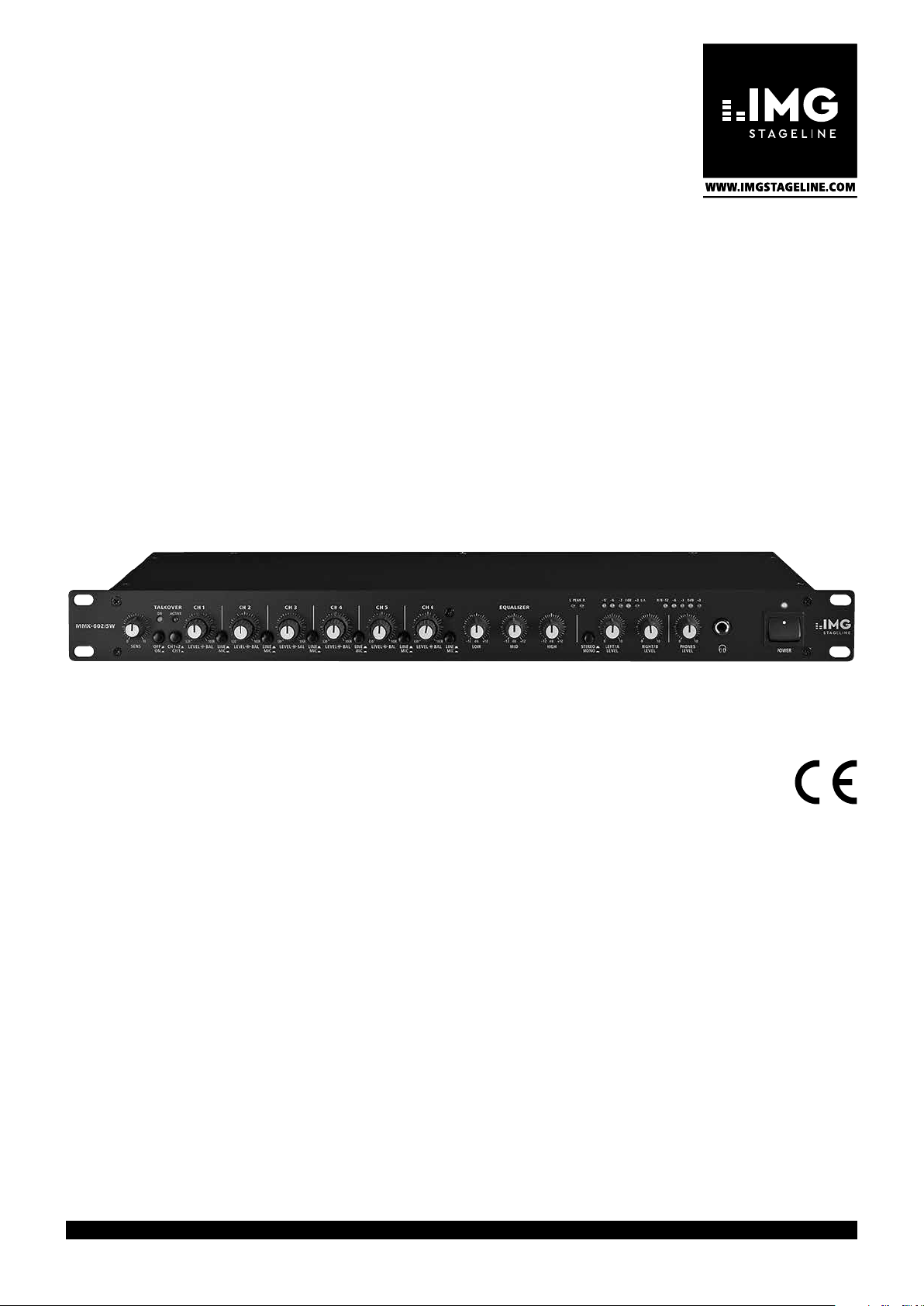
6-Kanal-Mikrofon / Line-Mischpult
6-Channel Mircophone / Line Mixer
MMX-602/SW
Bestell-Nr. • Order No. 20.2230
BEDIENUNGSANLEITUNG
INSTRUCTION MANUAL
MODE D’EMPLOI
ISTRUZIONI PER L’USO
VEILIGHEIDSVOORSCHRIFTEN
CONSEJOS DE SEGURIDAD
SIKKERHEDSOPLYSNINGER
SÄKERHETSFÖRESKRIFTER
TURVALLISUUDESTA
ELECTRONICS FOR SPECIALISTS ELECTRONICS FOR SPECIALISTS ELECTRONICS FOR SPECIALISTS ELECTRONICS FOR SPECIALISTS

Deutsch ...........Seite 4
English ............Page 6
Français ...........Page 8
Italiano............Pagina 10
Nederlands ........Pagina 12
Español ...........Página 12
Dansk .............Sida 12
Svenska ...........Sidan 13
Suomi.............Sivulta 13
ELECTRONICS FOR SPECIALISTS ELECTRONICS FOR SPECIALISTS ELECTRONICS FOR SPECIALISTS ELECTRONICS FOR SPECIALISTS
2
MMX-602/SW
1 2
TALKOVE R
CH 1
CH 2
CH 3
LINE
MIC
CH 4
L|0 10|R
LEVEL BAL
LINE
MIC
L|0 10|R
LEVEL BAL
ON
ACTIVE
L|0
L|0 10|R
LEVEL BAL
LINE
MIC
L|0 10|R
LEVEL BAL
0 10 0 10
SENS
OFFONCH1+2
6
7
10|R
LEVEL BAL
LINE
CH1
8 11
MIC
CH 6 EQUALIZER
CH 5
L|0 10|R
LINE
LEVEL BAL
MIC
-
12 dB +12
-
12 dB +12
LOW
LINE
MIC
MID
12 13 14 15 16 17109
3 54
PEAKL R
dB +12
-
12
STEREO
HIGH LEFT/A
MONO
-12-6-
LEVEL
3 0 dB +3-12-6-3 0 dB +3L/A R/B
0 10
RIGHT/B
LEVEL
0 10
PHONES
LEVEL
POWER
➀
230V~/50 Hz
L/ A R/ B
CH1 CH3CH2
JP101
OUTPUT
L/ A
R/ B
L
R
REC
21 22 23201918
JP201
12-V-Phantomspeisung
12 V phantom power
Alimentation fantôme 12 V
Alimentazione phantom 12 V
JP301
CH6 CH5 CH4 CH3 CH2 CH 1
L
PUSH PUSH PUSH PUSH PUSH PUSH
R
MIC LINE LINE MIC MIC LINE LINE MIC MIC LINE LINE MIC
L
R
L
R
L
R
L
R
L
R
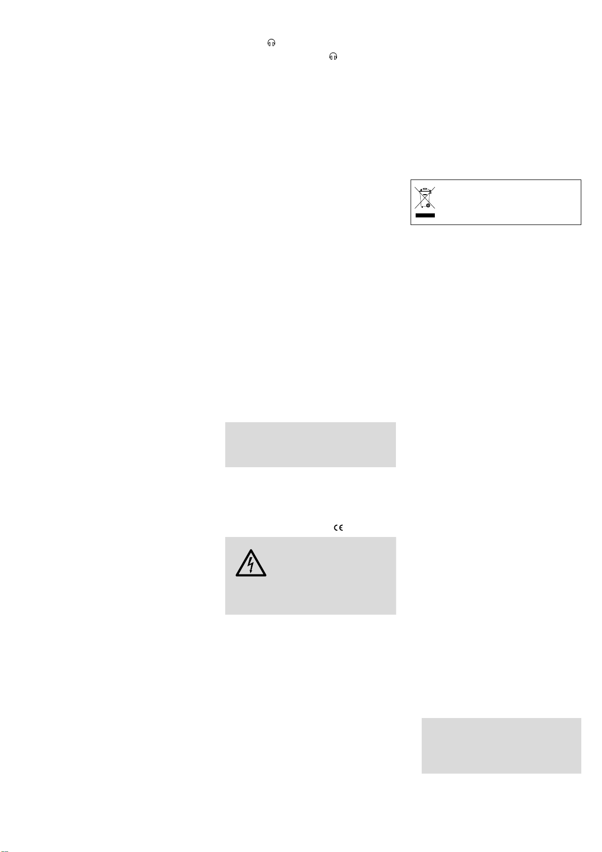
CH5
Aus
Off
Arrêt
JP401
CH1 – JP101
CH2 – JP201
.....
JP501
Ein
On
Marche
JP601
CH6 – JP601
➁
CH6CH4
➂
MONO
STEREO
VU-METER
LEVEL
LEFT/ A
LEVEL
RIGHT/ B
+
–
+
–
LEVEL PHONES
2
3
LEFT/ A
1
LEFT/ A
RIGHT/ B
OUTPUT
2
RIGHT/ B
3
1
REC L
REC R
L
LINE
R
2
MIC
3
1
PHANTOM
+12V
V+
JP101
MMX-602/SW
MIC
LINE
+
MIC
AMP
–
CH1
LEVEL
BALANCE
CH1+2
CH1
TALKOVER
V+
TALKOVER SENSITIVE
TALKOVER
ON
OFF
ON
ACTIVE
PEAK
±12dB
BASS MID TREBLE
±12dB
PEAK
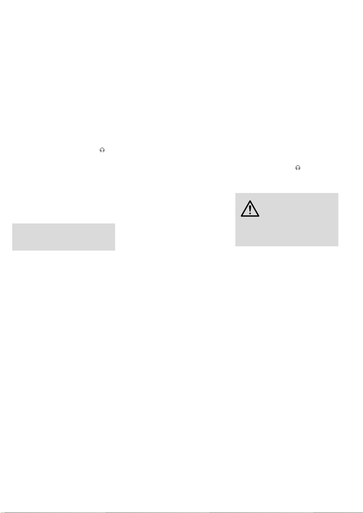
Blockschaltbild / Block diagram
Schéma bloc / Schema di connessione
➃
3
6-Kanal-Mikrofon / Line-Mischpult
Diese Bedienungsanleitung richtet sich an Benutzer ohne besondere Fachkenntnisse. Bitte
Deutsch
lesen Sie die Anleitung vor dem Betrieb gründlich durch und heben Sie sie für ein späteres
Nachlesen auf. Auf der ausklappbaren Seite 3
finden Sie alle beschriebenen Bedienelemente
und Anschlüsse.
1 Übersicht der Anschlüsse und
Bedienelemente
1.1 Frontseite (Abb. 1)
1 Anzeige ON
leuchtet bei eingeschalteter Talk overFunktion, siehe Position 7 Taste OFF/ON
2 Anzeige ACTIVE
leuchtet, wenn über die Talkover-Funktion
die Kanäle CH 2 – CH 6 bzw. CH 3 – CH 6
automatisch in der Lautstärke um 12 dB
abgesenkt sind
3 Übersteuerungsanzeige PEAK
bei Aufleuchten den entsprechenden Kanalpegelregler LEVEL (9) zurückdrehen
4 Pegelanzeige (2 × 5 LEDs) für die Ausgänge
(19) und (20)
5 Betriebsanzeige
6
Regler SENS für die Ansprechschwelle der
Talkover-Funktion
7
Taste OFF / ON zum Ein- /Ausschalten der Talkover-Funktion
8
Umschalter CH 1 + 2 / CH 1 zum Zuweisen der
Talkover-Funktion
Taste gedrückt: Liegt ein Line-Signal an
Kanal CH 1 an oder erfolgt eine Mikrofondurchsage über Kanal CH 1, werden zur besseren Verständlichkeit die Kanäle CH 2 bis
CH 6 in der Lautstärke um 12 dB abgesenkt
nicht gedrückt: Liegt ein Line-Signal an
Kanal CH 1 oder CH 2 an oder erfolgt eine
Mikrofondurchsage über CH 1 oder CH 2,
werden die Kanäle CH 3 bis CH 6 abgesenkt
9
vorderer Drehknopf LEVEL, jeweils für die
Kanäle CH 1 bis CH 6:
zum Einstellen des Kanalpegels
10
hinterer Drehring BAL, jeweils für die Kanäle
CH 1 bis CH 6:
zur Balance-Einstellung der Line-Eingänge
(22) bzw. um ein Mikrofonsignal auf die gewünschte Stelle in der Stereo-Basis zu legen
11
Eingangswahlschalter, jeweils für die Kanäle
CH 1 bis CH 6
Taste gedrückt: Der Mikrofoneingang über
die XLR-Buchse (23) ist angewählt
nicht gedrückt: Der Line-Eingang über die
Cinch-Buchsen (22) ist angewählt
12 Klangregler für alle Ausgänge (19, 20, 21)
LOW = Bassregler
MID = Mittenregler
HIGH = Höhenregler
13
Umschalter STEREO / MONO für den Betriebsmodus [nur für die Ausgänge (19) und
(20) wirksam]
Taste gedrückt: Mono-Betrieb
nicht gedrückt: Stereo-Betrieb
14 Pegelregler für die Ausgänge (19) und(20)
15
Lautstärkeregler LEVEL für einen an der
Buchse (16) angeschlossenen Kopfhörer
16
6,3-mm-Klinkenbuchse zum Anschluss
eines Kopfhörers (Impedanz mindestens
2× 8 Ω)
17 Ein-/Ausschalter POWER
1.2 Rückseite (Abb. 2)
18
Netzkabel zum Anschluss an eine Steckdose
(230 V/ 50 Hz)
19
XLR-Ausgang, symmetrisch, mono oder stereo in Abhängigkeit vom Umschalter(13)
20 Cinch-Ausgang, asymmetrisch, mono oder
stereo in Abhängigkeit vom Umschalter (13)
21
Aufnahme-Ausgang REC (stereo, CinchBuchsen, asym.); die Aufnahmelautstärke
ist von Stellung der Ausgangsregler (14)
unabhängig
22
Stereo-Eingang LINE für Geräte mit LineAusgang, z. B. CD-Spieler, Tape-Deck, Tuner
usw., jeweils für die Kanäle CH 1 bis CH 6
(Cinch-Buchsen, asym.)
23
Mikrofon-Eingang MIC, jeweils für die
Kanäle CH 1 bis CH 6 (XLR, symmetrisch)
1.3 Ausschnitt Innenansicht (Abb. 3)
Die Abbildung 3 zeigt die Lage der Steckbrücken JP101 bis JP601 (Blick von oben, Geräteabdeckung abgenommen). Mit den Brücken
lässt sich eine 12-V- Phantomspeisung für jeden
Mikrofoneingang getrennt dazuschalten. Bei
Auslieferung ab Werk ist die Phantomspeisung
ausgeschaltet. Detaillierte Beschreibung siehe
im Kapitel 4.1.
Achtung! Zum Zuschalten der Phantomspeisung muss das Mischpult geöffnet werden.
Darum darf dies nur durch eine qualifizierte
Fachkraft erfolgen.
2 Hinweise für den
sicherenGebrauch
Das Gerät entspricht allen relevanten Richtlinien
der EU und trägt deshalb das -Zeichen.
WARNUNG
Das Gerät ist nur zur Verwendung im-
•
Innenbereich geeignet. Schützen Sie es vor
Tropf- und Spritzwasser, hoher Luftfeuchtigkeit und Hitze (zulässiger Einsatztemperaturbereich 0 – 40 °C).
Stellen Sie keine mit Flüssigkeit gefüllten Ge-
•
fäße, z. B. Trinkgläser, auf das Gerät.
Nehmen Sie das Gerät nicht in Betrieb bzw.
•
ziehen Sie sofort den Netzstecker aus der
Steckdose,
1.
wenn sichtbare Schäden am Gerät oder am
Netzkabel vorhanden sind,
2.
wenn nach einem Sturz oder Ähnlichem
der Verdacht auf einen Defekt besteht,
3. wenn Funktionsstörungen auftreten.
Lassen Sie das Gerät in jedem Fall in einer
Fachwerkstatt reparieren.
Das Gerät wird mit lebensgefährlicher Netzspannung versorgt.
Nehmen Sie deshalb niemals
selbst Eingriffe daran vor. Durch
uns achbemäßes Vorgehen besteht die Gefahr eines elektrischen Schlages.
Ein beschädigtes Netzkabel darf nur durch
•
eine Fachwerkstatt ersetzt werden.
Ziehen Sie den Netzstecker nie am Kabel aus
•
der Steckdose, fassen Sie immer am Stecker an.
Verwenden Sie für die Reinigung nur ein tro-
•
ckenes, weiches Tuch, niemals Wasser oder
Chemikalien.
Wird das Gerät zweckentfremdet, falsch an-
•
geschlossen, nicht richtig bedient oder nicht
fachgerecht repariert, kann keine Haftung für
daraus resultierende Sach- oder Personenschäden und keine Garantie für das Gerät
übernommen werden.
Soll das Gerät endgültig aus dem Betrieb genommen werden, übergeben
Sie es zur umweltgerechten Entsorgung
einem örtlichen Recyclingbetrieb.
3 Einsatz- und
Aufstellmöglichkeiten
Mit diesem 6-Kanal-Mischpult lassen sich Geräte
mit Line-Ausgang (z. B. CD-Spieler, Tape-Deck,
Tuner) und Mikrofone (auch phantomgespeiste)
auf einen Stereo- oder Mono- Ausgangskanal
mischen. Der MMX-602 / SW eignet sich dadurch
z. B. als Vormischer für eine Mikrofongruppe
(Chor, Schlagzeug usw.) oder als Mischpult in
Beschallungsanlagen.
Das Gerät ist für die Montage in ein Rack
(482 mm / 19”) vorgesehen, kann aber auch als
freistehendes Tischgerät verwendet werden. Für
den Einbau in ein Rack wird 1 HE (Höheneinheit)
= 44,45 mm benötigt.
Hinweis: Werden phantomgespeiste Mikrofone angeschlossen, muss vor dem Einbau in ein Rack die
Phantomspeisung dazugeschaltet werden (siehe Kapitel 4.1).
4 Gerät anschließen
Vor dem Anschluss bzw. vor dem Verändern von
Anschlüssen das Mischpult und die anzuschließenden Geräte ausschalten.
Soll die Talkover-Funktion (siehe Kapitel 5.3)
genutzt werden, bei der Belegung der Kanäle
beachten, dass ein Signal auf Kanal CH 1 oder
CH 2 die Lautstärke der Kanäle CH 2 – CH 6 bzw.
CH 3 – CH 6 verringern kann. Beispiel: Kanäle
CH 1 und CH 2 für die Mikrofone der Sprecher
oder Akteure, die übrigen Kanäle für das Begleit
programm oder die Hintergrundmusik.
1)
Geräte mit Line-Pegel (z. B. CD-Spieler, Tape-Deck, Tuner usw.) an die sechs
Cinch-Buchsenpaare LINE (22) anschließen:
weiße Buchse LEFT = linker Kanal
rote Buchse RIGHT = rechter Kanal
2)
Mikrofone (symmetrisch oder asymmetrisch)
an die sechs XLR-Buchsen MIC (23) anschließen. Für phantomgespeiste Mikrofone die
Phantomspeisung dazuschalten – siehe Kapitel 4.1.
Vorsicht! Ist die Phantomspeisung dazugeschaltet, dürfen keine asymmetrischen
Mikrofone an den entsprechenden Kanälen
angeschlossen werden. Anderenfalls können
diese Mikrofone beschädigt werden.
Soll ein Mikrofonstecker wieder aus dem Mischpult herausgezogen werden, zur Entriegelung
die Taste PUSH der XLR-Buchse drücken.
-
4
3)
Den Endverstärker für die Lautsprecher oder
ein nachfolgendes Gerät mit Line-Eingang
(Hauptmischpult, Effektgerät etc.) an die
passenden Ausgangsbuchsen anschließen:
ein Gerät mit XLR-Eingang an die XLRBuchsen L /A und R/B (19) und /oder
ein Gerät mit Cinch-Eingang an die CinchBuchsen L /A und R / B (20)
4)
Ein Aufnahmegerät für Tonaufnahmen
kann an die Cinch-Buchsen REC (21) angeschlossen werden. Die Aufnahmelautstärke
ist unabhängig von der Einstellung der Ausgangspegelregler (14). Die Aufzeichnung
erfolgt unabhängig von der Stellung des
Schalters STEREO / MONO (13), d. h. immer
stereofon.
5)
Über einen Kopfhörer lässt sich das Ausgangssignal des Mischpultes abhören. Dazu
einen Kopfhörer (Impedanz minimal 2 ×
8 Ω) an die 6,3-mm-Klinkenbuchse (16)
anschließen.
6)
Zuletzt den Netzstecker des Anschlusskabels
(18) in eine Steckdose (230 V/ 50 Hz) stecken.
4.1 Mikrofon-Phantomspeisung dazuschalten
Um auch phantomgespeiste Mikrofone betreiben zu können, lässt sich für jeden Mikrofoneingang getrennt eine 12-V-Phantomspeisung
dazuschalten.
Achtung! Zum Zuschalten der Phantomspeisung muss das Mischpult geöffnet werden.
Darum darf dies nur durch eine qualifizierte
Fachkraft erfolgen.
1) Den Netzstecker aus der Steckdose ziehen.
2) Den Gehäusedeckel abschrauben.
3) Für die gewünschten Mikrofoneingänge die
entsprechenden Steckbrücken JP101 (für
Kanal CH 1) bis JP601 (für Kanal CH 6) von
Aus nach Ein, wie in Abb. 3 dargestellt, umstecken.
4) Den Gehäusedeckel wieder festschrauben.
5 Bedienung
1)
Vor dem Einschalten sollten die Ausgangspegelregler (14) auf Null gestellt werden, um
eventuelle Einschaltgeräusche zu vermeiden.
2) Das Gerät mit dem Ein-/Ausschalter POWER
(17) einschalten. Die rote Betriebsanzeige (5)
leuchtet.
3)
Die angeschlossenen Geräte einschalten,
zuletzt immer den Endverstärker für die
Lautsprecher.
4) Beim Ausschalten der Anlage immer zuerst
den Endverstärker abschalten.
5.1 Grundeinstellung
derEingangskanäle
1)
Zuerst die sechs Kanalpegelregler LEVEL [vorderer Drehknopf (9)] auf Null und die sechs
Balanceregler BAL [hinterer Drehring (10)]
in die Mittelposition stellen. Die Klangregler
LOW, MID und HIGH (12) ebenfalls in die
Mittelposition drehen.
2)
Für jeden Kanal mit dem Eingangswahlschalter LINE / MIC (11) den gewünschten Eingang
anwählen:
Taste gedrückt: Der Mikrofoneingang über
die XLR-Buchse (23) ist angewählt
nicht gedrückt: Der Line-Eingang über die
Cinch-Buchsen (22) ist angewählt
3)
Mit dem Umschalter STEREO / MONO (13) den
Betriebsmodus wählen:
Taste gedrückt: Mono-Betrieb; es stehen die
Mono-Ausgangskänale A und B mit gleichem
Mischsignal zur Verfügung
nicht gedrückt: Stereo-Betrieb; es steht
ein Stereo-Ausgangskanal LEFT/ RIGHT zur
Verfügung
5.2 Mischen der Tonquellen
1) Die Talkover-Funktion vorerst nicht einschalten, d. h. die Taste OFF/ON (7) darf nicht gedrückt sein.
2)
Auf alle angeschlossenen Eingänge ein Signal
geben (Testsignal, Musikstück oder Mikrofondurchsage).
3)
Damit über den Ausgang ein Signal zu hören
ist, die Ausgangspegelregler LEFT/A und
RIGHT/ B (14) vorerst ungefähr in die Position 7 drehen.
4)
Den vorderen Drehknopf LEVEL (9) des Kanals
oder der Kanäle, die am lautesten zu hören
sein sollen, soweit aufdrehen, bis die Anzeige
PEAK (3) bei den lautesten Passagen kurz aufleuchtet. Den oder die Regler wieder etwas
zurückdrehen.
5) Die übrigen Kanäle, die ebenfalls zu hören
sein sollen, mit den zugehörigen Drehknöpfen LEVEL entsprechend dazumischen.
6)
Arbeitet der MMX-602 / SW im Stereo- Betrieb
[Taste STEREO / MONO (13) nicht gedrückt],
für jeden Kanal mit dem hinteren Drehring
BAL (10) entweder die Balance des StereoSignals von den Cinch-Buchsen einstellen
oder das Mikrofonsignal auf die gewünschte
Stelle in der Stereo-Basis legen.
7) Den Klang mit den Reglern (14) einstellen:
LOW für die Bässe
MID für die Mitten
HIGH für die Höhen
8) Den Ausgangspegel mit den Reglern LEFT/A
und RIGHT/ B (14) so einstellen, dass bei den
lautesten Passagen die gelben 0-dB-LEDs der
Pegelanzeige (4) aufleuchten. Wird der Eingang des nachfolgenden Gerätes (Verstärker,
Mischpult) dadurch jedoch übersteuert, die
Regler entsprechend zurückdrehen.
Im Stereo-Betrieb mit den Ausgangspegelreglern (14) gleichzeitig die Balance des
Mischsignals einstellen. Im Mono-Betrieb können für die Ausgänge A und B unterschiedliche Pegel mit den Reglern eingestellt werden.
5.3 Talkover-Funktion
Mit der Talkover-Funktion lässt sich die Verständlichkeit z. B. einer Durchsage über Kanal
CH 1 oder CH 2 verbessern, indem während der
Durchsage automatisch die Lautstärke der anderen Kanäle um 12 dB reduziert wird.
1) Die Talkover-Funktion mit der Taste OFF/ ON
(7) einschalten. Zur Kontrolle leuchtet die
Anzeige ON (1).
2) Mit dem Umschalter CH 1 + 2 / CH 1 wählen,
durch welche Kanäle die anderen Kanäle in
der Lautstärke verringert werden sollen:
Taste gedrückt: Liegt ein Line-Signal an
Kanal CH 1 an oder erfolgt eine Mikrofondurchsage über Kanal CH 1, werden die
Kanäle CH 2 bis CH 6 in der Lautstärke verringert
nicht gedrückt: Liegt ein Line-Signal an
Kanal CH 1 oder CH 2 an oder erfolgt eine
Mikrofondurchsage über einen dieser Kanäle,
werden die Kanäle CH 3 bis CH 6 abgesenkt
3) Ein Signal auf Kanal CH 1 bzw. CH 2 geben
(z. B. eine Durchsage über Mikrofon) und den
Regler SENS (6) soweit aufdrehen, bis die
Anzeige ACTIVE (2) während der Durchsage
aufleuchtet. Die Anzeige ACTIVE leuchtet
immer dann, wenn die entsprechenden Kanäle abgesenkt sind.
Hinweis: Wird der Regler SENS zu weit aufgedreht,
kann die Lautstärkeabsenkung schon durch Störgeräusche ausgelöst werden. Ist der Regler nicht
weit genug aufgedreht, erfolgt gar keine Lautstärkeabsenkung oder nur bei lauten Signalen.
5.4 Abhören über einen Kopfhörer
Über einen an der Buchse (16) angeschlossenen Kopfhörer kann der Mischpultausgang
abgehört werden. Mit dem Regler LEVEL (15)
die Kopfhörerlautstärke einstellen.
VORSICHT
Ohr gewöhnt sich angroße Lautstärken und
empfindet sie nach einiger Zeit als nicht mehr
so hoch. Darum eine hohe Lautstärke nach der
Gewöhnung nicht weiter erhöhen.
Die Kopfhörerlautstärke ist von den Ausgangspegelreglern (14) unabängig. Auch bei auf Null
gestellten Ausgangsreglern kann dadurch das
Signal gehört werden.
Stellen Sie die Kopfhörerlautstärke am Verstärker nie sehr hoch
ein. Hohe Lautstärken können auf
Dauer das Gehör schädigen! Das
6 Technische Daten
Eingänge
6 × Line, stereo: � � � � � � 100 mV/ 10 kΩ, Cinch, asym�
6 × Mikrofon, mono: � � � 1 mV/ 6,6 kΩ, XLR, sym�
Ausgänge
Master, stereo oder mono
XLR, sym�: � � � � � � � � � 1 V/ 600 Ω
Cinch, asym�: � � � � � � � 1 V/ 600 Ω
1 × Record, stereo: � � � � 310 mV/ 600 Ω,Cinch, asym�
1 × Kopfhörer, stereo: � � ≥ 2 × 8 Ω, 6,3-mm-Klinke
Allgemeine Daten
Frequenzbereich: � � � � � � 20 – 20 000 Hz
Klirrfaktor: � � � � � � � � � � � 0,1 %
Störabstand: � � � � � � � � � 62 dB, unbewertet
Klangregler für die Ausgänge
1 × Tiefen: � � � � � � � � � ±12 dB / 50 Hz
1 × Mitten: � � � � � � � � ±12 dB / 1 kHz
1 × Höhen:� � � � � � � � � ±12 dB / 10 kHz
Talkover: � � � � � � � � � � � � −12 dB
Stromversorgung: � � � � � 230 V/ 50 Hz / 12 VA
Einsatztemperatur: � � � � 0 – 40 °C
Abmessungen (B × H × T): 482 × 47 × 208 mm, 1 HE
Gewicht: � � � � � � � � � � � � 2,8 kg
Änderungen vorbehalten.
Diese Bedienungsanleitung ist urheberrechtlich für
MONACOR ® INTERNATIONAL GmbH & Co. KG geschützt. Eine Reproduktion für eigene kommerzielle
Zwecke – auch auszugsweise – ist untersagt.
Deutsch
5

6-Channel Mikrophone / Line Mixer
These instructions are intended for users without
any specific technical knowledge. Please read
English
these instructions carefully prior to operating
the unit and keep them for later reference. All
operating elements and connections de scribed
can be found on the fold-out page 3.
1 Operating Elements
andConnections
1.1 Front panel (fig. 1)
1 Indication ON
lights up with the talkover function switched
on, see item 7 button OFF/ON
2 Indication ACTIVE
lights up if the volume of channels CH 2 to
CH 6 or CH 3 to CH6 is automatically attenuated by 12 dB via the talkover function
3 Overload indication PEAK
if it lights up, turn back the corresponding
channel level control LEVEL (9)
4 Level indication (2 × 5 LEDs) for the outputs
(19) and (20)
5 Power indication
6 Control SENS for the threshold of the talk-
over function
7
Button OFF/ON for switching the talkover
function on and off
8 Selector switch CH 1 + 2 / CH 1 to assign the
talk over function
Button pressed: if a line signal is present at channel CH 1 or if a microphone
announcement is made via chan nel CH 1,
the volume of channels CH 2 to CH 6 is
attenuated by 12 dB for better audibility
not pressed: if a line signal is present at
channel CH 1 or CH 2 or if a microphone
announcement is made via channel CH 1 or
CH 2, channels CH 3 to CH 6 are atten uated
9
Front rotary knob LEVEL, one each for channels CH 1 to CH 6:
to adjust the channel level
10 Rear rotary ring BAL, one each for channels
CH 1 to CH 6:
to adjust the balance of the line inputs
(22) or to place a microphone signal to the
desired spot in the stereo basis
11
Input selector switch, one each for channels
CH 1 to CH 6
button pressed: the microphone input is
select ed via the XLR jack (23)
not pressed: the line input is selected via
the phono jacks (22)
12 Equalizer for all outputs (19, 20, 21)
LOW = bass range control
MID = midrange control
HIGH = high range control
13
Selector switch STEREO / MONO for the
ope r ating mode [only effective for the
outputs (19) and (20)]
button pressed: mono operation
not pressed: stereo operation
14 Level controls for the outputs (19) and (20)
15 Volume control LEVEL for headphones con-
nected to the jack (16)
16 6.3 mm jack to connect headphones (im-
pedance 2 ×
17 POWER switch
8 Ω minimum)
1.2 Rear panel (fig. 2)
18
Mains cable for connection to a mains
socket (230 V/ 50 Hz)
19
XLR output, balanced, mono or stereo
depend ing on the selector switch (13)
20
RCA output, unbalanced, mono or stereo
depending on the selector switch (13)
21
Recording output REC (stereo, RCA jacks,
unbal.); the recording volume is independent of the position of the output level controls (14)
22
Stereo input LINE for units with line output, e. g. CD player, tape deck, tuner, etc.,
one each for channels CH 1 to CH 6 (phono
jacks, unbal.)
23 Microphone input MIC, one each for chan-
nels CH 1 to CH 6 (XLR, balanced)
1.3 Cutout of interior view (fig. 3)
Fig. 3 shows the position of the jumpers JP101
to JP601 (view from above, the cover of the
unit is re moved). With the jumpers, it is possible
to switch on a 12 V phantom power separately
for each microphone input. Upon delivery ex
factory, the phantom power is switched off. For
detailed description, see chapter 4.1.
Attention! To switch on the phantom power,
the mixer must be opened. This must only be
done by qualified personnel.
2 Safety Notes
This unit corresponds to all relevant directives of
the EU and is therefore marked with .
WARNING
The unit is suitable for indoor use only. Protect
•
it against dripping water and splash water,
high air humidity, and heat (admissible ambient temperature range 0 – 40 °C).
Do not place any vessels filled with liquid, e. g.
•
drink ing glasses, on the unit.
Do not set the unit into operation, and
•
immediately disconnect the mains plug from
the mains socket if
1.
there is visible damage to the unit or to
the mains cable,
2. a defect might have occurred after a drop
or similar accident,
3. there are malfunctions.
The unit must in any case be repaired by
skilled personnel.
A damaged mains cable must be replaced by
•
skilled personnel only.
Never pull the mains cable to disconnect the
•
mains plug from the mains socket, always
seize the plug.
For cleaning only use a dry, soft cloth, by no
•
means chemicals or water.
No guarantee claims for the unit and no
•
liability for any resulting personal damage or
The unit uses dangerous mains
voltage. Leave servicing to skilled
personnel only. Inexpert handling
or modification of the unit may
result in electric shock.
material damage will be accepted if the unit
is used for other purposes than originally intended, if it is not correctly operated, or if it
is not repaired in an expert way.
Important for U.K. Customers!
•
The wires in this mains lead are coloured in
accord ance with the following code:
blue = neutral; brown = live
As the colours of the wires in the mains
lead of this appliance may not correspond
with the coloured markings identifying the
terminals in your plug, proceed as follows:
1. The wire which is coloured blue must be
con nected to the terminal in the plug
which is mark ed with the letter N or
coloured black.
2. The wire which is coloured brown must be
connected to the terminal which is marked
with the letter L or coloured red.
If the unit is to be put out of operation
definitively, take it to a local recycling
plant for a disposal which is not harmful
to the environment.
3 Applications and Setting-up
With this 6-channel mixer, it is possible to mix
units with line output (e. g. CD player, tape deck,
tuner) and microphones (also phantom-powered) to a ster eo or mono output channel. Thus,
the MMX-602 / SW is suitable e. g. as pre-mixer
for a microphone group (chorus, drums, etc.) or
as mixer in PA systems.
The unit is provided for mounting into a
rack (482 mm / 19”), but it can also be used as
a table top unit. For the installation into a rack,
1rack space = 44.45 mm is required.
Note: if phantom-powered microphones are connected, the phantom power must be switched on prior
to the rack installation (see chapter 4.1).
4 Connection of the Unit
Prior to making or changing any connections,
switch off the mixer and the units to be connected.
For using the talkover function (see chapter 5.3):
when connecting the channels make sure that
a signal on channel CH 1 or CH 2 can change
the volume of channels CH 2 to CH 6 or CH 3
to CH 6. Example: CH 1 and CH 2 for the microphones of speaking or acting persons, the
remaining channels for the accompanying programme or the background music.
1)
Connect units with line level (e. g. CD
player, tape deck, tuner, etc.) to the six pairs
of phono jacks LINE (22):
white jack LEFT = left channel
red jack RIGHT = right channel
2)
Connect microphones (balanced or unbalanc ed) to the six XLR jacks MIC (23). For
phantom-powered microphones, switch on
the phantom power – see chapter 4.1.
Caution! If the phantom power is switched
on, no unbalanced microphones must be
connected to the corresponding channels.Otherwise these microphones may be
damaged.
For disconnecting a microphone plug from
the mixer, press the button PUSH of the XLR
jack for unlocking.
6

3)
Connect the power amplifier for the speakers or a subsequent unit with line input
(main mixer, effect unit, etc.) to the matching
output jacks:
a unit with XLR
and R / B (19) and / or
a unit with RCA input to the phono jacks
L /A and R / B (20)
4) A recording unit for audio recordings can
be connected to the phono jacks REC (21).
The re cord ing volume is independent of the
adjustment of the output level controls (14).
The record ing is made independent of the
position of switch STEREO / MONO (13), i. e.
it is always stereo phonic.
5)
Headphones can be used to monitor the
output signal of the mixer. For this purpose,
connect headphones (minimum impedance
8 Ω) to the 6.3 mm jack (16).
2 ×
6) Finally connect the mains plug of the cable
(18) to a mains socket (230 V/ 50 Hz).
input to the XLR jacks L /A
4.1 Switching on the microphone
phantom power
To be able to operate phantom-powered microphones as well, it is possible to switch on a 12 V
phantom power separately for each microphone
input.
Attention! To switch on the phantom power,
the mixer must be opened. This must only be
done by qualified personnel.
1) Disconnect the mains plug from the mains
socket.
2) Screw off the housing cover.
3)
For the desired microphone inputs, rearrange
the corresponding jumpers JP101 (for channel CH 1) to JP601 (for channel CH 6) from
Off to On, as shown in fig. 3.
4) Tightly screw on the housing cover again.
5 Operation
1) Prior to switching on, the output level controls (14) should be set to zero to avoid a
possible switching-on noise.
2) Switch on the unit with the POWER switch
(17). The red power indication (5) lights up.
3)
Switch on the connected units, always switch
on the power amplifier for the speakers last
of all.
4)
When switching off the system, always
switch off the power amplifier first.
5.1 Basic setting of the input channels
1) First set the six channel level controls LEVEL
[front rotary knob (9)] to zero and the six
balance controls BAL [rear rotary ring (10)] to
mid-position. Set the equalizer controls LOW,
MID, and HIGH (12) likewise to mid-position.
2)
Select the desired input for each channel with
the input selector switch LINE / MIC (11):
button pressed: the microphone input is
selected via the XLR jack (23)
not pressed: the line input is selected via the
phono jacks (22)
3) Select the operating mode with the selector
switch STEREO / MONO (13):
button pressed: mono operation; the mono
output channels A and B are available with
the same mixing signal
not pressed: stereo operation; a stereo output channel LEFT / RIGHT is available
5.2 Mixing of the audio sources
1) Do not switch on the talkover function for
the time being, i. e. the button OFF/ ON (7)
must not be pressed.
2)
Feed a signal to all connected inputs (test signal, music piece, or microphone announcement).
3)
To be able to hear a signal via the output,
turn the output level controls LEFT/A and
RIGHT/ B (14) approx. to position 7 for the
time being.
4)
Turn up the front rotary knob LEVEL (9) of the
channel(s), which are to be heard at highest
volume, until the indication PEAK (3) shortly
lights up with the music peaks. Slightly turn
back again the control(s).
5) Add the remaining channels which are to be
heard as well with the corresponding rotary
knobs LEVEL accordingly.
6)
If the MMX-602 / SW is in stereo operation
[button STEREO / MONO (13) not pressed],
adjust for each channel with the rear rotary ring BAL (10) either the balance of the
stereo signal of the RCA jacks or apply the
microphone signal to the desired spot in the
stereo basis.
7) Adjust the sound with the controls (14):
LOW for the bass range
MID for the midrange
HIGH for the high range
8)
Adjust the output level with the controls
LEFT/A and RIGHT/ B (14) so that the yellow
0 dB LEDs of the level indication (4) light
up with music peaks. However, if the input
of the subsequent unit (amplifier, mixer) is
overloaded by this, turn back the controls
correspondingly.
In stereo operation, adjust the balance
of the mixing signal with the output level
controls (14) at the same time. In mono
operation, a different level for the outputs
A and B can be adjusted with the controls.
5.3 Talkover function
With the talkover function, the audibility e. g. of
an announcement via channel CH 1 or CH 2 can
be improved if the volume of the other channels
is automatically attenuated by 12 dB during the
announcement.
1)
Switch on the talkover function with the
button OFF/ ON (7). The indication ON (1)
lights up.
2)
Select with the selector switch CH 1 + 2 / CH 1
by which channels the volume of the other
channels is to be attenuated:
button pressed: if a line signal is present at
CH 1 or if a microphone announce-
channel
ment is made via channel
of channels
not pressed: if a line signal is present at
chan nel CH 1 or CH 2 or if a microphone
announcement is made via one of these
CH 2 to CH 6 is attenuated
CH 1, the volume
channels, channels CH 3 to CH 6 are attenuated.
3) Feed a signal to channel CH 1 or CH 2 (e. g.
an announcement via microphone) and turn
up the control SENS (6) until the indication
ACTIVE (2) lights up during the announcement. The indication ACTIVE always lights
up in case the corresponding channels are
attenuated.
Note: If the control SENS is turned up too much,
the volume attenuation can already be released by
interfering noise. If the control is not turned up far
enough, there is either no volume attenuation at
all or only in case of high volume signals.
5.4 Monitoring via headphones
Via headphones connected to one of the jack
(16), the mixer output can be monitored.
Adjust the headphone volume with the control
LEVEL (15).
CAUTION Never adjust the headphones to
a very high volume. Permanent
high volumes may damage your
hearing! The human ear will get
accustomed to high volumes which do not
seem to be that high any more after some
time. Therefore, do not further in crease a high
volume after getting used to it.
The headphone volume is independent of the
output level controls (14). Thus, it is possible to
monitor the signal even if the output controls
are set to zero.
6 Specifications
Inputs
6 × line, stereo:
6 × microphone, mono: � 1 mV/ 6�6 kΩ, XLR, balanced
Outputs
Master, stereo or mono
XLR, bal: � � � � � � � � � � � 1 V/ 600 Ω
RCA, unbal�: � � � � � � � � 1 V/ 600 Ω
1 × Record, stereo: � � � � 310 mV/ 600 Ω, RCA, unbal�
1 × headphones, stereo: ≥ 2 × 8 Ω, 6�3 mm jack
General information
Frequency range:
THD: � � � � � � � � � � � � � � � 0�1 %
S / N ratio: � � � � � � � � � � � 62 dB, unweighted
Equalizer for the outputs
1 × bass: � � � � � � � � � � ±12 dB / 50 Hz
1 × midrange: � � � � � � ±12 dB / 1 kHz
1 × high: � � � � � � � � � � ±12 dB / 10 kHz
Talkover: � � � � � � � � � � � � –12 dB
Power supply: � � � � � � � � 230 V/ 50 Hz /12 VA
Ambient temperature: � � 0 – 40 °C
Dimensions (W × H × D): 482 × 47 × 208 mm,
Weight:
Subject to technical modification.
All rights reserved by MONACOR ® INTERNATIONAL
GmbH & Co. KG. No part of this instruction manual
may be reproduced in any form or by any means for
any commercial use.
� � � � � � � 100 mV/ 10 kΩ RCA, unbal�
� � � � � � 20 – 20 000 Hz
1 rack space
� � � � � � � � � � � � � 2�8 kg
English
7

Mixeur Micro / Ligne 6 canaux
Cette notice s‘adresse aux utilisateurs sans
connaissances techniques particulières. Veuillez
Français
lire la présente notice avant le fonctionnement
et conservez-la pour pouvoir vous y reporter
ultérieurement. Vous trouverez sur la page 3,
dépliable, les éléments et branchements décrits.
1 Eléments et branchements
1.1 Face avant (schéma 1)
1 LED ON
brille lorsque la fonction Talkover est activée,
voir position 7 touche OFF/ ON
2 LED ACTIVE
brille lorsque, via la fonction Talkover, le volume des canaux CH 2 – CH 6 ou CH 3 – CH 6
est diminué automatiquement de 12 dB
3 LED PEAK témoin d’écrêtage
si elle brille, tournez le réglage de niveau
LEVEL (9) du canal dans l’autre sens
4
VU-mètre à LEDs (2 × 5 LEDs) pour les sorties
(19) et (20)
5 Témoin de fonctionnement
6
Réglage SENS pour régler le seuil de déclenchement du fonction Talkover
7
Touche ON / OFF pour activer / désactiver la
fonction Talkover
8 Commutateur CH 1 + 2 / CH 1 pour l’attribu-
tion de la fonction Talkover
touche enfoncée : si un signal Ligne est
présent sur le canal CH 1 ou si une annonce
micro a lieu via le canal CH 1, le volume des
canaux CH 2 à CH 6 sera diminué de 12 dB
pour améliorer la compréhension
touche non enfoncée : si un signal Ligne
est présent sur le canal CH 1 ou CH 2 ou
si une annonce micro a lieu via le canal
CH 1 ou CH 2, les canaux CH 3 à CH 6 sont
diminués.
9 Bouton rotatif avant LEVEL pour les canaux
CH 1 à CH 6 : réglage de niveau du canal
10 Anneau rotatif arrière BAL pour les canaux
CH 1 à CH 6 : réglage de la balance des entrées Ligne (22) ou mise à disposition d’un
signal micro sur la base stéréo souhaitée
11 Sélecteur d’entrée pour les canaux CH 1 à
CH 6
touche enfoncée : l’entrée micro est sélec-
tionnée via la prise XLR (23)
touche non enfoncée : l’entrée Ligne est
sélectionnée via les prises RCA (22)
12
Egaliseur pour toutes les sorties (19, 20, 21)
LOW = réglage des graves
MID = réglage des médiums
HIGH = réglage des aigus
13
Commutateur STEREO / MONO pour le mode
de fonctionnement [effectif uniquement
pour les sorties (19) et (20)] :
touche enfoncée : mode mono
touche non enfoncée : mode stéréo
14
Réglages de niveau pour les sorties (19)
et(20)
15 Réglage de volume LEVEL pour un casque
relié à la prise
(16)
16
Prise jack 6,35 mm pour connecter un
casque (impédance minimale 2 x 8 Ω)
17 Interrupteur général POWER Marche /Arrêt
1.2 Face arrière (schéma 2)
18
Cordon secteur : pour brancher l’appareil
au secteur 230 V/ 50 Hz
19
Sortie XLR, symétrique, mono ou stéréo
selon la position du commutateur (13)
20
Sortie RCA, asymétrique, mono ou stéréo
selon la position du commutateur (13)
21
Sortie enregistrement REC (stéréo, prises
RCA, asymétriques) ; le volume d’enregistrement est indépendant de la position des
réglages de niveau (14) pour les sorties
22 Entrée stéréo LINE pour des appareils à sor-
tie niveau Ligne, p. ex. lecteur CD, tuner,
tape deck, etc., pour les canaux CH 1 à CH 6
(prises RCA, asymétriques)
23 Entrée micro MIC, pour les canaux CH 1 à
CH 6 (XLR, symétriques)
1.3 Vue intérieure (schéma 3)
Le schéma 3 présente la position des cavaliers
JP101 à JP601 (vue de dessus, couvercle retiré).
Avec les cavaliers, il est possible de connecter
séparément pour chaque entrée micro une alimentation fantôme 12 V. L’alimentation fantôme
est déconnectée en sortie d’usine. Pour une description détaillée voir chapitre 4.1.
Attention! Seul un technicien habilité peut
effectuer le branchement de l’alimentation fantôme car la table de mixage doit être ouverte.
2 Conseils d‘utilisation
Cet appareil répond à toutes les directives
nécessaires de l’Union européenne et porte
donc le symbole .
AVERTISSEMENT Cet appareil est alimenté par
une tension dangereuse. Ne
touchez jamais l’intérieur
de l’appareil car, en cas de
mauvaise manipulation, vous
pourriez subir une décharge
électrique.
L’appareil n’est conçu que pour une utilisation
•
en intérieur. Protégez-le des éclaboussures, de
tout type de projections d’eau, de l’humidité
et de la chaleur (température ambiante admissible 0 – 40 °C).
En aucun cas, vous ne devez poser d’objet
•
contenant du liquide ou un verre sur l’appareil.
Ne faites pas fonctionner l’appareil ou dé-
•
branchez immédiatement la prise du cordon
du secteur lorsque :
1. des dommages apparaissent sur l’appareil
ou sur le cordon secteur,
2. après une chute ou un cas similaire, vous
avez un doute sur l’état de l’appareil,
3. des dysfonctionnements apparaissent.
Faites toujours appel à un technicien spécialisé
pour effectuer les réparations.
Tout cordon secteur endommagé doit être
•
remplacé impérativement par un technicien
spécialisé.
Ne débranchez jamais l’appareil en tirant
•
sur le cordon secteur, tenez-le toujours par
la prise.
Pour nettoyer l’appareil, utilisez uniquement
•
un chiffon sec et doux, en aucun cas, de produits chimiques ou d’eau.
Nous déclinons toute responsabilité en cas de
•
dommages corporels ou matériels résultants
si l’appareil est utilisé dans un but autre que
celui pour lequel il a été conçu, s’il n’est pas
correctement branché ou utilisé ou s’il n’est
pas réparé par une personne habilitée, de
même, la garantie deviendrait caduque.
Lorsque l’appareil est définitivement re
tiré du service, vous devez le déposer
dans une usine de recyclage adaptée
pour contribuer à son élimination non
polluante.
CARTONS ET EMBALLAGE
PAPIER À TRIER
3 Possibilités d’utilisation
Cette table de mixage 6 canaux permet de mixer
des appareils à niveau Ligne (p. ex. lecteur CD,
tape deck, tuner) et micros (aussi à alimentation
fan tôme) sur un signal de sortie stéréo ou mono.
Le MMX-602 / SW est bien adapté pour une utilisation comme prémixeur pour un groupe de
micros (chœur, batterie, etc.) ou comme table
de mixage dans des installations de sonorisation.
La table de mixage est conçue pour une
installation en rack (482 mm / 19”), 1 U est nécessaire. Il est également possible de la poser
directement sur une table.
Remarque : si des micros à alimentation fantôme
doivent être branchés, il faut commuter l’alimentation
fantôme avant de placer la table de mixage dans un
rack (voir chapitre 4.1).
4 Branchements
Avant d’effectuer ou de modifier tout branchement, vérifiez que la table de mixage et les
appareils reliés sont bien éteints.
Si la fonction Talkover (voir chapitre 5.3) doit
être utilisée, veillez à la configuration des canaux : un signal sur le canal CH 1 ou CH 2 peut
diminuer le volume des canaux CH 2 – CH 6 ou
CH 3 – CH 6. Exemple : les canaux CH 1 et CH 2
pour les micro d’orateurs ou d’acteurs, les autres
canaux pour le programme d’accompagnement
ou la musique d’arrière-fonds.
1) Reliez les appareils à niveau Ligne (p. ex.
lecteur CD, tape-deck, tuner, etc.) aux
6prises RCA LINE (22) :
prise blanche LEFT = canal gauche
prise rouge RIGHT = canal droit
2)
Reliez les micros (symétriques ou asymétriques) aux 6 prises XLR MIC (23). Commutez l’alimentation fantôme pour les micros
à alimentation fantôme (voir chapitre 4.1).
Attention ! Si l’alimentation fantôme est
con nectée, aucun micro asymétrique ne
doit être relié aux canaux correspondants,
il pourrait être endommagé.
Si une prise micro doit être retirée de la table
de mixage, enfoncez la touche PUSH de la
prise XLR pour la déverrouiller.
-
8

3)
Reliez l’amplificateur de puissance pour
les haut-parleurs ou l’appareil suivant à
entrée Ligne (table de mixage principale,
appareil à effets, etc.) aux prises de sortie
correspondantes :
appareil à entrée XLR
R / B (19) et / ou
appareil à entrée RCA aux prises RCA L /A
et R / B (20)
4) Un enregistreur pour des enregistrements
audio peut être relié aux prises RCA REC (21);
le volume d’enregistrement est indépendant
de la position des réglages de niveau (14)
pour les sorties. L’enregistrement se fait indépendamment de la position du commutateur
STEREO / MONO (13), c’est-à-dire il est toujours stéréophonic.
5) Vous pouvez effectuer une préécoute du signal de sortie de la table de mixage via un
casque : reliez un casque (impédance minimale 2 × 8 Ω) à la prise jack 6,35 mm (16).
6)
Reliez maintenant le cordon secteur (18) à
une prise secteur 230 V/ 50 Hz.
aux prises XLR L /A et
4.1 Commutation alimentation
fantôme pour les micros
Pour pouvoir faire fonctionner des micros à alimentation fantôme, il est possible de connecter
pour chaque entrée micro séparément, une alimentation fantôme 12 V.
Attention! Seul un technicien habilité peut
effectuer le branchement de l’alimentation fantôme car la table de mixage doit être ouverte.
1) Retirez le cordon secteur de la prise.
2) Dévissez le couvercle du boîtier.
3) Pour les entrées micros souhaitées, commutez les cavaliers correspondants JP101 (pour
canal CH 1) à JP601 (pour canal CH 6) de
«Arrêt» vers «Marche» (sché ma 3).
4) Revissez le couvercle.
5 Utilisation
1)
Avant d’allumer la table de mixage, vérifiez que les réglages de niveau (14) pour
les sorties de vraient être sur le minimum,
de manière à éviter tout bruit fort lors de
l’allumage.
2) Allumez la table de mixage avec l’interrupteur POWER (17), le témoin de fonctionnement rouge (5) s’allume.
3) Allumez les appareils reliés, toujours l’amplificateur de puissance pour les haut-parleurs
en dernier.
4) Veillez à toujours éteindre l’amplificateur de
puissance en premier, puis l’ensemble du
système.
5.1 Réglages de base des
canauxd’entrée
1) Mettez les 6 réglages de niveau LEVEL des
ca naux [bouton rotatif avant (9)] sur zéro et
les 6 réglages de balance BAL [anneau rotatif
arrière (10)] sur la position médiane. Mettez
également les réglages égaliseur LOW, MID,
HIGH (12) sur la position médiane.
2)
Pour chaque canal, sélectionnez l’entrée avec
le sélecteur LINE / MIC (11) :
touche enfoncée : l’entrée micro est sélectionnée via la prise XLR (23)
touche non enfoncée : l’entrée LINE est
sélectionnée via les prises RCA (22)
3) Avec le commutateur STEREO / MONO (13),
choisissez le mode de fonctionnement :
touche enfoncée : mode mono ; les sorties
mono A et B sont à disposition avec le même
signal mixé
touche non enfoncée : mode stéréo ; un
signal de sortie stéréo LEFT/ RIGHT est mis à
disposition
5.2 Mixage des sources
1)
N’activez pas la fonction Talkover pour le
moment, c’est-à-dire la touche OFF/ ON (7)
ne doit pas être enfoncée.
2)
Appliquez un signal à toutes les entrées
branchées (signal test, pièce de musique ou
annonce micro).
3) Pour pouvoir écouter un signal sur la sortie,
tournez pour l’instant les réglages de niveau
LEFT/A et RIGHT/ B (14) pour les sorties environ sur la position 7.
4) Tournez le bouton rotatif avant LEVEL (9) du
canal ou des canaux dont le volume doit être
plus fort jusqu’à ce que la LED PEAK (3) brille
brièvement pour les passages les plus forts.
Tournez le bouton ou les boutons un peu
en arrière.
5)
Mixez les canaux restants qui doivent être
également écoutés avec les boutons rotatifs
LEVEL correspondants.
6)
Si la table de mixage fonctionne en mode
stéréo [touche STEREO / MONO (13) non
enfoncée], réglez pour chaque canal avec
l’anneau rotatif arrière BAL (10) la balance
du signal stéréo des prises RCA ou mettez
le signal micro sur la position voulue sur la
base stéréo.
7) Réglez la tonalité avec les réglages (14) :
LOW pour les graves
MID pour les médiums
HIGH pour les aigus
8) Réglez le niveau de sortie avec les réglages
LEFT/A et RIGHT/ B (14) de telle sorte que
pour des passages plus forts, les LEDs jaunes
0 dB du VU-mètre (4) brillent. Pourtant, si
l’entrée de l’appareil suivant (amplificateur,
table de mixage) est en surcharge par cela,
diminuez les réglages correspondamment.
En mode stéréo, réglez simultanément la
ba lance du signal mixé avec les réglages de
niveau (14) pour les sorties. En mode mono,
des ni veaux différents pour les sorties A et B
peuvent être ajustés avec les réglages.
5.3 Fonction Talkover
La fonction Talkover permet d’améliorer la
com préhension, p. ex. d’une annonce effectuée
sur le canal CH 1 ou CH 2, en diminuant automatiquement pendant l’announce le volume des
autres canaux de 12 dB.
1) Allumez la fonction Talkover avec la touche
ON / OFF (7) ; la LED ON (1) brille.
2)
Avec le commutateur CH 1 + 2 / CH 1, sélectionnez par quels canaux le volume des
autres ca naux doit être diminué :
touche enfoncée : si un signal Ligne est présent sur le canal CH 1 ou une annonce micro
est effectuée via le canal CH 1, le volume des
canaux CH 2 à CH 6 est diminué.
touche non enfoncée : si un signal Ligne est
présent sur le canal CH 1 ou CH 2 ou une annonce est effectuée via un de ces canaux, le
volume des canaux CH 3 à CH 6 est diminué.
3)
Appliquez un signal sur le canal CH 1 ou
CH 2 (p. ex. une annonce micro) et tournez
le réglage SENS (6) jusqu’à ce que la LED
ACTIVE (2) s’allume pendant l’annonce. La
LED ACTIVE brille toujours lorsque les canaux
correspondants sont diminués.
Remarque : Si le réglage SENS est trop tourné, la
diminution de volume peut déjà être déclenchée
par les bruits perturbateurs. Si le réglage n’est pas
assez tourné, il n’y a aucune diminution de volume
ou uniquement pour des signaux très forts.
5.4 Préécoute par un casque
Il est possible de faire une préécoute de la sortie
table de mixage via un casque relié à la prise
(16). Réglez le volume du casque avec le ré-
glage LEVEL (15).
ATTENTION
s’habitue à des volumes forts et ne les perçoit
plus, au bout d’un certain temps, aussi forts.
C’est pourquoi n’augmentez pas un volume
élevé une fois habitué.
Le volume du casque est indépendant des
réglages de niveau (14) pour les sorties. Même
s’ils sont sur zéro, le signal peut être écouté.
Ne réglez pas le volume du casque
trop fort. Des volumes élevés
peuvent à la longue générer des
troubles de l’audition. L’oreille
6 Caractéristiques techniques
Entrées
6 × Ligne stéréo :
6 × Ligne micro : � � � � � � 1 mV/ 6,6 kΩ, XLR, sym�
Sorties
1 × Master stéréo ou mono
XLR, sym� : � � � � � � � � � 1 V/ 600 Ω
RCA, asym� : � � � � � � � � 1 V/ 600 Ω
1 × Record, stéréo : � � � � 310 mV/ 600 Ω, RCA, asym�
1 × casque, stéréo : � � � � ≥ 2 × 8 Ω, ack 6,35 mm
Généralités
Bande passante :
Taux de distorsion : � � � � 0,1 %
Rapport signal / bruit : � � 62 dB, non pondéré
Egaliseur pour les sorties
1 × graves : � � � � � � � � ±12 dB / 50 Hz
1 × médiums : � � � � � � ±12 dB / 1 kHz
1 × aigus : � � � � � � � � � ±12 dB / 10 kHz
Talkover : � � � � � � � � � � � −12 dB
Alimentation : � � � � � � � � 230 V/ 50 Hz /12 VA
Température ambiante : � 0 – 40 °C
Dimensions : � � � � � � � � � 482 × 47 × 208 mm, 1 U
Poids : � � � � � � � � � � � � � � 2,8 kg
Tout droit de modification réservé.
Notice d’utilisation protégée par le copyright de
MONACOR ® INTERNATIONAL GmbH & Co. KG. Toute
reproduction même partielle à des fins commerciales
est interdite.
� � � � � 100 mV/10 kΩ, RCA, asym�
� � � � � � 20 – 20 000 Hz
Français
9

Mixer microfono / Line a 6 canali
Queste istruzioni sono rivolte all‘utente senza
conoscenze tecniche specifiche. Vi preghiamo
Italiano
di leggerle attentamente prima della messa in
funzione e di conservarle per un uso futuro. A
pagina 3, se aperta completamente, vedrete
sempre gli elementi di comando e i collegamenti
descritti.
1 Elementi di comando
ecollegamenti
1.1 Pannello frontale (fig. 1)
1 Spia ON
è accesa con funzione talkover attivata, vedi
pos. 7, tasto OFF/ ON
2 Spia ACTIVE
è accesa se con la funzione talkover il volume dei canali CH 2 – CH 6 o CH 3 – CH 6 è
abbassato automaticamente di 12 dB
3 Spia di sovrapilotaggio PEAK
se si accende occorre abbassare il regolatore
LEVEL (9) del relativo canale
4
Indicazione del livello (2 × 5 LED) per le
uscite (19) e (20)
5 Spia di funzionamento
6
Regolatore SENS per la soglia di reazione
della funzione di talkover
7
Tasto OFF/ ON per dis / attivare la funzione
talk over
8
Selettore CH 1 + 2 / CH 1 per assegnare la
funzione talkover
tasto premuto: se al canale CH 1 è presente
un segnale Line oppure se si fa un avviso col
microfono tramite CH 1, il volume dei canali
da CH 2 a CH 6 viene abbassato di 12 dB per
facilitare la comprensione
tasto non premuto: se ai canali CH 1 o
CH 2 è presente un se gnale Line oppure se
si fa un avviso col microfono tramite CH 1
o CH 2, il volume dei canali da CH 3 a CH 6
viene abbassato
9 Manopola anteriore LEVEL per i canali CH 1
a CH 6: per regolare il livello del canale
10
Anello posteriore BAL, per i canali CH 1 a
CH 6:
per impostare il bilanciamento degli ingressi
Line (22) oppure per mettere un segnale del
micro fono sul lato desiderato della base
stereo
11
Selettore d’ingresso, per i canali CH 1 a CH 6
tasto premuto: è selezionato l’ingresso
microfono con la presa XLR (23)
tasto non premuto: è selezionato l’in-
gresso Line con le prese cinch (22)
12 Regolatore toni per le uscite (19, 20, 21)
LOW = regolatore bassi
MID = regolatore medi
HIGH = regolatore alti
13
Commutatore STEREO / MONO per la mo
dalità di funzionamento [solo per le uscite
(19) e (20)]
tasto premuto: funzionamento mono
tasto non premuto: funzionamento stereo
14 Regolatore livello per le uscite (19) e (20)
15
Regolatore volume LEVEL per una cuffia
collegata con la presa (16)
16
Presa jack 6,3 mm per collegare una cuffia
(impedenza minima 2 x 8 Ω)
17 Interruttore on / off POWER
1.2 Pannello posteriore (fig. 2)
18 Cavo rete da collegare ad una presa (230 V/
50 Hz)
19
Uscita XLR, simmetrica, mono o stereo a
se con da del commutatore (13)
20 Uscita cinch, asimmetrica, mono o stereo, a
se con da del commutatore (13)
21
Uscita registrazione REC (stereo, prese cinch,
asimm.); il volume della registrazione è indipendente dalla posizione dei regolatori
d’uscita (14)
22
Ingresso stereo Line per apparecchi con
uscita Line, p. es. lettori CD, tape deck, tuner
ecc., per i canali CH 1 a CH 6 (prese cinch,
asimm.)
23 Ingresso microfono MIC, per i canali CH 1 a
CH 6 (XLR, simmetrico)
1.3 Particolare dell’interno (fig. 3)
La figura 3 indica la posizione dei jumper JP101
a JP601 (visti dall’alto, tolto il coperchio). Con i
jumper è possibile aggiungere per ogni ingresso
microfono un’alimentazione phantom 12 V.
L’apparecchio viene fornito con l’alimentazione
phantom disattivata. Una descrizione particolareggiata si trova nel capitolo 4.1.
Attenzione! Per attivare l’alimentazione phantom occorre aprire il mixer. Tale operazione può
essere eseguita pertanto solo da una persona
esperta e qualificata.
2 Avviso di sicurezza
Quest’apparecchio è conforme a tutte le direttive rilevanti dell’UE e pertanto porta la sigla .
AVVERTIMENTO
L’apparecchio è previsto solo per l’uso all’in-
•
terno di locali. Proteggerlo da acqua gocciolante, dagli spruz zi d‘acqua, da alta umidità
dell‘aria e dal calore (temperatura d’impiego
ammessa fra 0 °C e 40 °C).
Non depositare sull’apparecchio contenitori
•
con li qui di, p. es. bicchieri.
Non mettere in funzione l’apparecchio e stac-
•
care subito la spina rete se:
1. l’apparecchio o il cavo rete presentano dei
danni visibili;
2. dopo una caduta o dopo eventi simili sus-
-
siste il sospetto di un difetto;
3.
l’apparecchio non funziona correttamente.
Per la riparazione rivolgersi sempre ad un’officina competente.
Il cavo rete, se danneggiato, deve essere so-
•
stituito solo da un laboratorio specializzato
Staccare il cavo rete afferrando la spina, senza
•
ti rare il cavo.
L’apparecchio funziona con
pericolosa tensione di rete.
Non intervenire mai personalmente al suo interno. La
manipolazione scorretta può
provocare delle scariche elettriche pericolose.
Per la pulizia usare solo un panno morbido,
•
asciutto; non impiegare in nessun caso prodotti chimici o acqua.
Nel caso d’uso improprio, di collegamenti
•
sbagliati, d’impiego scorretto o di riparazione
non a regola d’arte dell’apparecchio, non si
assume nessuna re sponsabilità per eventuali
danni consequenziali a persone o a cose e non
si assume nessuna garanzia per l’apparecchio.
Se si desidera eliminare l’apparecchio
definitivamente, consegnarlo per lo
smaltimento ad un’istituzione locale
per il riciclaggio.
3 Possibilità d’impiego
edicollocamento
Con questo mixer a 6 canali si possono miscelare
apparecchi con ingresso Line (p. es. lettori CD,
tape deck, tuner) e microfoni (anche con alimentazione phantom) su un canale d’uscita mono
o stereo. L’MMX-602 / SW è pertanto adatto per
esempio come premixer per un gruppo di microfoni (coro, batteria ecc.) oppure come mixer
in un impianto di sonorizzazione.
L’apparecchio è previsto per il montaggio
in un rack (482 mm / 19”), ma può essere collocato anche liberamente su un tavolo. Per il
montaggio in un rack è richiesta un’unità di
altezza (=44,45 mm).
N. B.: Se si usano microfoni con alimentazione phantom, occorre attivare tale alimentazione prima del
montaggio nel rack (vedi cap. 4.1).
4 Collegare l’apparecchio
Spegnere il mixer e gli apparecchi da collegare
prima di effettuare o modificare i collegamenti.
Se si desidera sfruttare la funzione talkover
(vedi capitolo 5.3) si deve tener presente che
un segnale sui canali CH 1 o CH 2 può ridurre
il volume dei canali CH 2 – CH 6 o CH 3 – CH 6.
Esempio: canali CH 1 e CH 2 per i microfoni per
i oratori, gli altri canali per il programma o per
la musica di sottofondo.
1)
Collegare apparecchi con livello Line
(p. es. lettori CD, tape deck, tuner ecc.) con
le 6coppie di prese cinch LINE (22):
presa bianca LEFT = canale di sinistra
presa rossa RIGHT = canale di destra
2)
Collegare i microfoni (simmetrici o asimme
trici) con le 6 prese XLR MIC (23). Per i microfoni con alimentazione phantom attivare tale
alimentazione – vedi capitolo 4.1.
Attenzione! Se è attivata l’alimentazione
phan tom, non si devono collegare microfoni asimmetrici ai relativi canali. Altrimenti
i microfoni po trebbero essere danneggiati.
Per staccare un connettore per microfono
dal mix er, premere il pulsante PUSH della
presa XLR.
3)
Collegare l’amplificatore finale per gli
altoparlanti o un apparecchio a valle con
ingresso Line (mixer principale, unità per
effetti ecc.) con le relative prese d’uscita:
un apparecchio con ingresso XLR con le prese
XLR L /A e R / B (19), e / o
un apparecchio con ingresso cinch con le
prese cinch L /A e R / B (20).
-
10

4)
Un registratore audio può essere collegato
con le prese cinch REC (21). Il volume di registrazione è indipendente dalla posizione dei
regolatori d’uscita (14).
La registrazione si fa indipendentemente
dalla posizione del commutatore STEREO /
MONO (13); infatti, si tratta sempre di una
registrazione stereofonica.
5) Tramite una cuffia è possibile ascoltare il se-
gnale d’uscita del mixer. Per fare ciò collegare
una cuffia (impedenza minima 2 × 8 Ω) con
la presa jack 6,3 mm (16).
6) Alla fine inserire la spina del cavo di rete (16)
in una presa (230 V/ 50 Hz).
4.1 Attivare l’alimentazione phantom
per i microfoni
Per poter usare anche microfoni con alimentazione phantom è possibile attivare per ogni
ingresso mi crofono un’alimentazione phantom
12 V.
Attenzione! Per attivare l’alimentazione phantom occorre aprire il mixer. Tale operazione può
essere eseguita pertanto solo da una persona
esperta e qualificata.
1) Staccare la spina di rete dalla presa.
2) Svitare il coperchio.
3) Spostare i relativi jumper JP101 (per il canale
CH 1) a JP601 (per il canale CH 6) dei vari ingressi microfono da off a on, come illustrato
in figura 3.
4) Avvitare di nuovo il coperchio.
5 Funzionamento
1)
Prima dell’accensione portare i regolatori
d’uscita (14) sullo zero per evitare eventuali
rumori di commutazione.
2) Quindi accendere il mixer con l’interruttore
POWER (17). Si accende la spia rossa di funzionamento (5).
3)
Accendere gli apparecchi collegati, per ultimo sempre l’amplificatore finale per gli
altoparlanti.
4)
Per spegnere l’impianto spegnere sempre per
primo l’amplificatore finale.
5.1 Impostazioni base dei
canalid’ingresso
1) Portare per prima cosa i sei regolatori LEVEL
dei canali [manopola anteriore (9)] sullo
zero e i sei regolatori del bilanciamento BAL
[anello poste riore (10)] in posizione centrale.
Portare anche i regolatori dei toni LOW, MID
e HIGH (12) in posizione centrale.
2) Con il selettore LINE / MIC (11) scegliere l’ingres so desiderato:
tasto premuto: è selezionato l’ingresso micro fono con la presa XLR (23)
tasto non premuto: è selezionato l’ingresso
Line con le prese cinch (22)
3)
Con il commutatore STEREO / MONO (13)
selezionare la modalità di funzionamento:
tasto premuto: funzionamento mono; sono
disponibili i canali d’uscita mono A e B con
un identico segnale misto
tasto non premuto: funzionamento stereo;
è dis ponibile un canale d’uscita stereo LEFT/
RIGHT
5.2 Miscelare le sorgenti
1)
Per il momento non attivare la funzione
talkover: il tasto OFF/ ON (7) non deve essere premuto.
2) Portare un segnale su tutti gli ingressi collegati (segnale di test, brano musicale o avviso
col microfono).
3)
Per poter sentire il segnale all’uscita, portare i regolatori del livello d’uscita LEFT/A
e RIGHT/ B (14) momentaneamente in posizione 7.
4)
Aprire la manopola anteriore LEVEL (9) del
ca nale o dei canali che si vuole che siano più
forti, finché la spia PEAK (3) non si accenda
brevemente nei passaggi più forti. Quindi
ridurre leggermente il livello.
5)
Miscelare gli altri canali che si devono sentire
servendosi delle relative manopole LEVEL.
6)
Se l’MMX-602 / SW è nella modalità stereo
[tasto STEREO / MONO (13) non premuto],
impostare per ogni canale o il bilanciamento
del segnale stereo proveniente dalle prese
cinch, servendosi dell’anello posteriore BAL
(10), oppure portare il segnale microfono sul
lato desiderato della base stereo.
7) Impostare i toni con i regolatori (14):
LOW per i bassi
MID per i medi
HIGH per gli alti
8)
Impostare il livello d’uscita con i regolatori
LEFT/A e RIGHT/ B (14) in modo tale che nei
passaggi più forti si accendano i LED gialli di
0 dB del livello (4). Se l’ingresso dell’appa
recchio a valle (amplificatore, mixer) dovesse
essere sovrapilotato, oc corre abbassare leggermente i regolatori.
Nel funzionamento stereo, impostare il
bilanciamento del segnale misto servendosi
dei regolatori del livello d’uscita (14). Nel
funzionamento mono, per le uscite A e B
si possono impostare con questi regolatori
livelli differenti.
5.3 Funzione talkover
La funzione talkover serve per rendere più comprensibili gli avvisi fatti sui canali CH 1 o CH 2,
perché durante gli avvisi i livelli degli altri canali
vengono abbassati automaticamente di 12 dB.
1)
Attivare la funzione talkover con il tasto OFF/
ON (7). Si accende la spia ON (1).
2)
Con il selettore CH 1 + 2 / CH 1 scegliere i
canali che devono causare la riduzione di
volume degli altri canali:
tasto premuto: se al canale CH 1 è presente
un segnale Line oppure se si fa un avviso col
microfono tramite
CH 2 a CH 6 viene abbassato
da
tasto non premuto: se ai canali CH 1 o CH 2
è presente un segnale Line oppure se si fa un
avviso col microfono tramite CH 1 o CH 2,
il volume dei canali da CH 3 a CH 6 viene
abbassato
CH 1, il volume dei canali
3)
Portare un segnale sul canale CH 1 o CH 2
(p. es. un avviso col microfono) ed aprire il
regolatore SENS (6) finché la spia ACTIVE
(2) non si accenda durante l’avvio. La spia
ACTIVE è accesa ogni volta che il volume dei
relativi canali è abbassato.
N.B.: Se il regolatore SENS viene aperto troppo,
l’abbassamento del volume può essere provocata
anche da disturbi collaterali. Se invece è aperto
troppo poco, l’abbassamento non avviene affatto
o solo con segnali molto forti.
5.4 Ascolto tramite una cuffia
Con una cuffia collegata alla presa (16) è
possibile ascoltare l’uscita del mixer. Impostare
il volume con il regolatore LEVEL (15).
ATTENZIONE Mai tenere molto alto il volume
nelle cuffie. A lungo andare, il
volume eccessivo può procurare
danni all’udito! L’orecchio si abitua agli alti volumi e dopo un certo tempo non
se ne rende più conto. Perciò non aumentare il
volume successivamente.
Il volume della cuffia non dipende dai regolatori
del livello d’uscita (14). Anche se tali regolatori si
trovano sullo zero è possibile ascoltare il segnale.
6 Dati tecnici
Ingressi
6 × Line, stereo:
6 × microfono, mono: � � 1 mV/ 6,6 kΩ, XLR, simm�
Uscite
Master, stereo o mono
-
XLR, simm�: � � � � � � � � 1 V/ 600 Ω
cinch, asimm�: � � � � � � 1 V/ 600 Ω
1 × Record, stereo: � � � � 310 mV/ 600 Ω,
1 × cuffia, stereo: � � � � � ≥ 2 × 8 Ω, jack 6,3 mm
Dati generali
Banda passante:
Fattore di distorsione: � � 0,1 %
Rapporto S / R: � � � � � � � � 62 dB, non valutato
Regolazione toni delle uscita
1 × bassi: � � � � � � � � � � ±12 dB / 50 Hz
1 × medi: � � � � � � � � � � ±12 dB / 1 kHz
1 × alti: � � � � � � � � � � � ±12 dB / 10 kHz
Talkover: � � � � � � � � � � � � –12 dB
Alimentazione: � � � � � � � 230 V/ 50 Hz / 12 VA
Temperatura d’impiego: � 0 – 40 °C
Dimensioni (L × H × P): � 482 × 47 × 208 mm,
� � � � � � � � � � � � � � � 2,8 kg
Peso:
Con riserva di modifiche tecniche.
La MONACOR ® INTERNATIONAL GmbH & Co. KG si
riserva ogni diritto di elaborazione in qualsiasi forma
delle presenti istruzioni per l’uso. La riproduzione –
anche parziale – per propri scopi commerciali è vietata.
� � � � � � 100 mV/10 kΩ, cinch, asimm�
cinch, asimm�
� � � � � � 20 – 20 000 Hz
1 unità di altezza
Italiano
11

Lees aandachtig de onderstaande veiligheidsvoorschriften, alvorens de apparatuur in gebruik
te ne men. Mocht u bijkomende informatie over
de bediening van de apparatuur nodig hebben,
lees dan de Duitse, Engelse, Franse, of Italiaanse
tekst van deze handleiding.
NederlandsEspañol
Veiligheidsvoorschriften
Dit apparaat is in overeenstemming met alle
relevante EU-Richtlijnen en is daarom met
gekenmerkt.
WAARSCHUWING De netspanning van het ap-
paraat is levensgevaarlijk.
Open het apparaat niet,
want door onzorgvuldige
ingrepen loopt u het risico
van elektrische schokken.
Het toestel is enkel geschikt voor gebruik bin-
•
nenshuis. Bescherm het tegen drup-, spatwater, hoge vochtigheid en hitte (toegestane
omgevings tem pe ratuur: 0 – 40 °C).
Plaats geen met vloeistof gevulde voorwerpen
•
zoals drinkglazen, etc. op het apparaat.
Stel het volume van de hoofdtelefoon nooit
•
zeer hoog in. Langdurige blootstelling aan
hoge volumes kan het gehoor beschadigen!
Het gehoor raakt aangepast aan hoge volumes die na een tijdje niet meer zo hoog lijken.
Verhoog daarom het volume niet nog meer,
nadat u er gewoon aan bent geraakt.
Schakel het apparaat niet in resp. trek onmid-
•
dellijk de stekker uit het stopcontact,
1.
wanneer het apparaat of het netsnoer
zichtbaar beschadigd is,
2.
wanneer er een defect zou kunnen optreden nadat het apparaat bijvoorbeeld is
gevallen,
3. wanneer het apparaat slecht functioneert.
Het apparaat moet in elk geval hersteld wor-
den door een gekwalificeerd vakman.
Een defect snoer mag enkel door een gekwa-
•
lificeerd persoon hersteld worden.
Trek de stekker nooit met het snoer uit het
•
stopcontact, maar steeds met de stekker zelf.
Verwijder het stof met een droge, zachte
•
doek. Gebruik zeker geen water of chemicaliën.
In geval van ongeoorloofd of verkeerd ge-
•
bruik, verkeerde aansluiting, foutieve bediening of van herstelling door een niet-gekwalificeerd persoon vervalt de garantie en de
verantwoordelijkheid voor hieruit resulterende
materiële of lichamelijke schade.
Wanneer het apparaat definitief uit bedrijf wordt genomen, bezorg het dan voor
milieuvriendelijke verwerking aan een
plaatselijk recyclagebedrijf�
Deze gebruiksaanwijzing is door de auteurswet be
schermd eigendom van MONACOR ® INTERNATIONAL
GmbH& Co. KG. Een reproductie – ook gedeeltelijk–
voor eigen commerciële doeleinden is verboden.
-
Por favor, antes del uso del aparato observar en
to do caso las instrucciones de seguridad siguientes. Si informaciones adicionales son necesarias
para la operación del aparato, estas se encuentran en el texto alemán, inglés, francés o italiano
de estas instrucciones.
Consejos de utilización
Este aparato cumple con todas las directivas
relevantes por la UE y por lo tanto está marcado
con el símbolo .
ADVERTENCIA El aparato utiliza un voltaje pe-
ligroso. Deje el mantenimiento
en manos del personal cualificado. El manejo inexperto o la
modificación del aparato pueden provocar una descarga.
El aparato está fabricado solo para una uti-
•
lización en interior. Protegerlo de todo tipo
proyecciones de agua, de las salpicaduras,
de la humedad y del calor (temperatura de
funcionamiento autorizado: 0 – 40 °C).
Læs nedenstående sikkerhedsoplysninger opmærksomt igennem før ibrugtagning af enheden. Bortset fra sikkerhedsoplysningerne
Dansk
henvises til den engelske, tyske, franske eller
italienske tekst.
Vigtige sikkerhedsoplysninger
Denne enhed overholder alle relevante EU direktiver og er derfor mærket med .
ADVARSEL
Enheden er kun beregnet til indendørs brug.
•
Beskyt den mod vanddråber og -stænk, høj
luftfugtighed og varme (tilladt omgivelsestemperatur 0 – 40 °C).
Enheden benytter livsfarlig netspænding. Udfør aldrig nogen
form for modifikationer på produktet og indfør aldrig genstande
i ventilationshullerne, da du dermed risikere at få elektrisk stød.
No poner recipientes llenados de líquido, p. ej.
•
vasos, sobre el aparato.
No ajuste nunca los auriculares en un volumen
•
muy elevado. Los volúmenes permanentes muy
elevados pueden dañar su oído. El oído humano se acostumbra a los volúmenes altos que
no lo parecen tanto después de un rato. Por
lo tanto, no aumente un volumen alto que ya
se había ajustado antes de acostumbrarse a él.
No haga funcionar el aparato y desconéctelo
•
inmediatamente cuando:
1.
aparecen daños en el aparato o el cable
de conexión
2.
después de una caída o accidente similar, el
aparato puede presentar un defecto.
3. mal funcionamiento aparece.
En todos los casos solo una persona habili-
tada y calificada está autorizada a efectuar
las reparaciones.
Un cable de corriente dañado sólo puede
•
repararse por el personal cualificado.
Undgå at placere væskefyldte genstande, som
•
f. eks. glas, ovenpå enheden.
Indstil ikke hovedtelefonernes lydniveau for
•
højt. Vedvarende højt lydtryk kan være skadeligt for den lyttende person! Det menneskelige øre vænner sig til højt lydtryk, således
at dette efter en tids forløb ikke føles så højt.
Skru derfor ikke yderligere op for lyden, når
De efter nogen tid har vænnet Dem til det
høje lydtryk.
Tag ikke enheden i brug og tag straks stikket
•
ud af stikkontakten i følgende tilfælde:
1. hvis der er synlig skade på enheden eller
netkablet,
2. hvis der kan være opstået skade, efter at
enheden er tabt eller lignende,
3. hvis der forekommer fejlfunktion.
Enheden skal altid repareres af autoriseret
personel.
Et beskadiget netkabel må kun repareres af
•
forhandleren eller autoriseret personel.
No desconecte nunca el aparato tirando del
•
cable, sujételo siempre por la toma de la
extremidad.
Para limpiar el aparato, utilice únicamente un
•
paño seco y suave, no utilice en ningún caso
productos químicos o agua.
Rechazamos toda responsabilidad en caso de
•
daños corporales o materiales si el aparato se
utiliza en otro fin para el cual ha sido fabricado, si no está correctamente conectado,
utilizado o si las reparaciones no se efectúan
por una persona habilitada; además por todos
estos mismos motivos el aparato carecería de
todo tipo de garantía.
Si va a poner el aparato fuera de servicio
definitivamente, llévelo a la planta de reciclaje de la zona para que su eliminación
no sea perjudicial para el medio ambiente�
Manual de instrucciones protegido por el copyright de
MONACOR ® INTERNATIONAL GmbH & Co. KG. Toda
reproducción mismo parcial para fines comerciales
está prohibida.
Tag aldrig netstikket ud af stikkontakten ved
•
at trække i kablet, tag fat i selve stikket.
Til rengøring må kun benyttes en tør, blød
•
klud; der må under ingen omstændigheder
benyttes kemikalier eller vand.
Hvis enheden benyttes til andre formål, end
•
den oprindeligt er beregnet til, hvis den ikke
er tilsluttet korrekt, hvis den betjenes forkert,
eller hvis den ikke repareres af autoriseret
personel, omfattes eventuelle skader ikke af
ga rantien.
Hvis enhederne skal tages ud af drift for
bestandigt, skal de bringes til en lokal genbrugsstation for bortskaffelse�
Alle rettigheder til denne brugsvejledning tilhører
MONACOR ® INTERNATIONAL GmbH & Co. KG. Ingen
dele af denne vejledning må reproduceres under ingen
omstændigheder til kommerciel anvendelse.
12

Innan enheten tas i bruk, läs först igenom säkerhetsföreskrifterna. Om ytterligare information
önskas, läs igenom den tyska, engelska, franska
eller den italienska texten som medföljer.
Säkerhetsföreskrifter
Enheten uppfyller relevanta Eu-direktiv och har
därför försetts med symbolen
VARNING Enheten använder högspänning
internt. Gör inga modifieringar
i enheten eller stoppa föremål
i ventilhålen. Risk för elskador
föreligger.
Enheten är endast avsedda för inomhusbruk.
•
Skydda enheten mot vätskor, hög luftfuktighet och hög värme (tillåten omgivningstemperatur 0 – 40 °C).
Placera inte föremål innehållande vätskor,
•
t. ex. dricksglas, på enheten.
.
Justera aldrig hörlurarna till en väldigt hög
•
ljudnivå. Permanent höga volymer kan ge
upphov till hörselskador! Örat vänjer sig vid
höga volymer vilken efter ett tag inte längre
verkar så hög. Därför bör man ej ytterligare
höja volymen efter att man vant sig.
Använd inte enheten och ta omedelbart kon-
•
takten ur eluttaget om något av följande fel
uppstår:
1. Enheten eller elsladden har synliga skador.
2. Enheten är skadad av fall e. d.
3. Enheten har andra felfunktioner.
Enheten skall alltid lagas på verkstad av ut-
bildad personal.
En skadad elsladd skall bytas på verkstad.
•
Drag aldrig ut kontakten genom att dra i
•
elsladden utan ta tag i kontaktkroppen.
Rengör endast med en mjuk och torr trasa,
•
använd aldrig kemikalier eller vatten vid rengöring.
Om enheten används för andra ändamål än
•
avsett, om den kopplas in felaktigt, om den
används på fel sätt eller inte repareras av auktoriserad personal upphör alla garantier att
gälla och inget ansvar tas heller för uppkommen skada på person eller materiel.
Om enheten ska tas ur drift slutgiltigt, ta
den till en lokal återvinningsanläggning för
en avyttring som inte är skadligt för miljön�
Alla rättigheter är reserverade av MONACOR ®
INTERNATIONAL GmbH & Co. KG. Ingen del av denna
instruktionsmanual får eftertryckas i någon form eller
på något sätt användas i kommersiellt syfte.
Svenska
Ole hyvä ja huomioi aina seuraavat turvallisuutta
koskevat ohjeet ennen laitteen käyttöön ottoa.
Katso käyttöön liittyviä ohjeita Saksan, Englannin, Ranskan tai Italian kielisistä ohjeista, jos
tarvitset lisää tietoa laitteen käytöstä.
Turvallisuusohjeet
Tämä laite täyttää kaikki siihen kohdistuvat
EU-direktiivit ja sille on myönnetty hyväksyntä.
VAROITUS
Tämä laite soveltuu vain sisätilakäyttöön. Suo-
•
jele laitetta kosteudelta, vedeltä ja kuumuudelta (sallittu ympäröivä lämpötila 0 – 40 °C).
Tämä laite toimii hengenvaarallisella jännitteellä. Älä koskaan
tee mitään muutoksia laitteeseen
taikka asenna mitään ilmanvaihto
aukkoihin, koska siitä saattaa
seurata sähköisku.
Älä sijoita laitteen päälle mitään nestettä
•
sisältävää, kuten vesilasia tms.
Älä säädä kuulokkeiden äänenvoimakkuutta
•
liian kovalle, koska jatkuva voimakas ääni
voi vahingoittaa kuuloa. Ota huomioon, että
korva tottuu kovaan ääneen, joka tuntuu sen
jälkeen todellista hiljaisemmalta, Jos kuuntelet kovaa, älä enää nosta äänenvoimakkuutta
kun olet tottunut siihen.
Irrota virtajohto pistorasiasta välittömästi,
•
äläkä ota laitetta käyttöön jos:
1. laitteessa tai virtajohdossa on näkyvä vaurio,
2. putoaminen tai vastaava vaurio on saattanut aiheuttaa vian,
3. laitteessa on toimintahäiriöitä.
Laite täytyy kaikissa näissä tapauksissa huollattaa valtuutetussa huoltoliikkeessä.
Vahingoittuneen verkkojohdon saa korjata
•
vain hyväksytty huolto.
Älä koskaan irrota virtajohtoa pistorasiasta
•
johdosta vetämällä.
Käytä puhdistamiseen pelkästään kuivaa,
•
pehmeää kangasta. Älä käytä kemikaaleja
tai vettä.
Laitteen takuu raukeaa, eikä valmistaja,
•
maahantuoja tai myyjä ota vastuuta mahdollisista välittömistä tai välillisistä vahingoista,
jos laitetta on käytetty muuhun kuin alkuperäiseen käyttötarkoitukseen, laitetta on
taitamattomasti käytetty tai kytketty tai jos
laitetta on huollettu muussa kuin valtuutetussa huollossa.
Kun laite poistetaan lopullisesti käytösta,
vie se paikalliseen kierrätyskeskukseen jälkikäsittelyä varten�
Kaikki oikeudet pidätetään MONACOR ® INTERNATIONAL GmbH & Co. KG. Mitään tämän käyttöohjeen osaa ei saa jäljentää miltään osin käytettäväksi
mihinkään kaupallisiin tarkoituksiin.
Suomi
13

MONACOR INTERNATIONAL GmbH & Co. KG • Zum Falsch 36 • 28307 Bremen • Germany
Copyright© by MONACOR INTERNATIONAL. All rights reserved.
A-0361.99.03.06.2016
 Loading...