

IMG STAGE LINE MMX-206 Instruction Manual
BEDIENUNGSANLEITUNG • INSTRUCTION MANUAL
MODE D’EMPLOI • ISTRUZIONI PER L‘USO • GEBRUIKSAANWIJZING • MANUAL DE INSTRUCCIONES
SIKKERHEDSOPLYSNINGER • SÄKERHETSFÖRESKRIFTER • TURVALLISUUDESTA
MMX-206 Best.-Nr. 20.1820
PROFESSIONELLES
16-KANAL-AUDIOMISCHPULT
PROFESSIONAL 16-CHANNEL AUDIO MIXER
TABLE DE MIXAGE AUDIO PROFESSIONELLE 16 CANAUX
MIXER AUDIO PROFESSIONALE A 16 CANALI


3
wwwwww..iimmggssttaaggeelliinnee..ccoomm
Bevor Sie einschalten ...
Wir wünschen Ihnen viel Spaß mit Ihren neuen Geräten
von „img Stage Line“. Dabei soll Ihnen diese Bedienungsanleitung helfen, alle Funktionsmöglichkeiten kennen zu
lernen. Die Beachtung der Anleitung vermeidet außerdem
Fehlbedienungen und schützt Sie und Ihre Geräte vor
eventuellen Schäden durch unsachgemäßen Gebrauch.
Den deutschen Text finden Sie auf den Seiten 4–17.
Before you switch on ...
We wish you much pleasure with your new “img Stage
Line” units. With these operating instructions you will be
able to get to know all functions of the units. By following
these instructions false operations will be avoided, and
possible damage to yourself and your units due to improper use will be prevented.
You will find the English text on the pages 4– 17.
D
A
CH
GB
Avant toute mise en service ...
Nous vous remercions d’avoir choisi des appareils “img
Stage Line” et vous souhaitons beaucoup de plaisir à les
utiliser. Cette notice a pour objectif de vous aider à mieux
connaître les multiples facettes des appareils. En outre,
en respectant les conseils donnés, vous éviterez toute
mauvaise manipulation de sorte que vous-même et vos
appareils soient protégés de tout dommage.
La version française se trouve pages 18–31.
Prima di accendere ...
Vi auguriamo buon divertimento con i Vostri apparecchi
nuovi “img Stage Line”. Le istruzioni per l’uso Vi possono
aiutare a conoscere tutte le possibili funzioni. E rispettando quanto spiegato nelle istruzioni, evitate di commettere degli errori, e così proteggete Voi stessi, ma anche gli apparecchi, da eventuali rischi per uso improprio.
Il testo italiano lo potete trovare alle pagine 18–31.
F
B
CH
I
Inden De tænder for apparatet ...
Vi ønsker Dem god fornøjelse med Deres nye system fra
“img Stage Line”. Læs oplysningerne for en sikker brug
af apparaterne før ibrugtagning. Følg sikkerhedsoplysningerne for at undgå forkert betjening og for at beskytte Dem og apparaterne mod skade på grund af forkert brug.
Sikkerhedsoplysningerne finder De på side 46.
Förskrift
Vi önskar dig mycket nöje med din nya enhet från “img
Stage Line”. Läs gärna säkerhetsinstruktionerna innan
du använder enheterna. Genom att följa säkerhetsinstruktionerna kan många problem undvikas, vilket
annars kan skada enheterna.
Du finner säkerhetsinstruktionerna på sidan 46.
DK S
Ennen virran kytkemistä ...
T oivomme, että uusi “img Stage Line”-laitteesi tuo sinulle
paljon iloa ja hyötyä. Ole hyvä ja lue käyttöohjeet ennen
laitteen käyttöönottoa. Luettuasi käyttöohjeet voit käyttää laitetta turvallisesti ja vältyt laitteen väärinkäytöltä.
Käyttöohjeet löydät sivulta 46.
FIN
Voordat u inschakelt ...
Wij wensen u veel plezier met uw nieuw toestel van “img
Stage Line”. Met behulp van bijgaande gebruiksaanwijzing zal u alle functiemogelijkheden leren kennen.
Door deze instructies op te volgen zal een slechte werking vermeden worden, en zal een eventueel letsel aan
uzelf en schade aan uw toestel tengevolge van onzorgvuldig gebruik worden voorkomen.
U vindt de nederlandstalige tekst op de pagina’s 32–45.
Antes de cualquier instalación ...
Tenemos de agradecerle el haber adquirido un aparato
“img Stage Line” y le deseamos un agradable uso. Este
manual quiere ayudarle a conocer las multiples facetas
de este aparato. La observación de las instrucciones
evita operaciones erróneas y protege Vd. y vuestro aparato contra todo daño posible por cualquier uso inadecuado.
La versión española se encuentra en las páginas 32–45.
NL
B
E

4
Inhalt
1 Einsatzmöglichkeiten . . . . . . . . . . . . . . . . .4
2 Wichtige Hinweise für den Gebrauch . . . . 4
3 Übersicht der Bedienelemente und
Anschlüsse . . . . . . . . . . . . . . . . . . . . . . . . . 5
3.1 Mono-Kanalzüge 1–14 . . . . . . . . . . . . . . . . 5
3.2 Stereo-Kanalzüge M1 und M2 . . . . . . . . . . . 7
3.3 Ausgangsfeld . . . . . . . . . . . . . . . . . . . . . . . . 8
3.4 Rückseite . . . . . . . . . . . . . . . . . . . . . . . . . . 10
3.5 Netzgerät . . . . . . . . . . . . . . . . . . . . . . . . . . 10
4 Modifikationen der Kanalzüge . . . . . . . . . 10
4.1 Phantomspeisung für einzelne Mono-
Kanalzüge abschalten . . . . . . . . . . . . . . . . 11
4.2 Phantomspeisung für einzelne Stereo-
Kanalzüge dazuschalten . . . . . . . . . . . . . . . 11
4.3 Signalauskoppelpunkte der Auskoppel-
wege A3 bis A6 ändern . . . . . . . . . . . . . . . . 11
5 Geräte anschließen . . . . . . . . . . . . . . . . . . 11
5.1 Netzgerät . . . . . . . . . . . . . . . . . . . . . . . . . . 11
5.2 Verstärker . . . . . . . . . . . . . . . . . . . . . . . . . . 11
5.3 Kopfhörer . . . . . . . . . . . . . . . . . . . . . . . . . . 11
5.4 Mikrofone . . . . . . . . . . . . . . . . . . . . . . . . . . 12
5.5 Instrumente und Geräte mit Line-Ausgang . 12
5.6 Effektgeräte . . . . . . . . . . . . . . . . . . . . . . . . . 12
5.7 Aufnahmegeräte . . . . . . . . . . . . . . . . . . . . . 13
6 Bedienung . . . . . . . . . . . . . . . . . . . . . . . . . 13
6.1 Grundeinstellung der Eingangskanäle . . . . 13
6.1.1 Vorbereitung . . . . . . . . . . . . . . . . . . . . . . . 13
6.1.2 Kanalzüge auf die Subgruppen oder
auf die Ausgangssumme L-R schalten . . 13
6.1.3 Eingangskanäle aussteuern und
Klang einstellen . . . . . . . . . . . . . . . . . . . . 13
6.2 Eingangssignale mischen . . . . . . . . . . . . . . 14
6.3 Auskoppelwege konfigurieren und
Stage-Modus aktivieren . . . . . . . . . . . . . . . 15
6.4 Abhören der Kanäle . . . . . . . . . . . . . . . . . . 16
7 Technische Daten . . . . . . . . . . . . . . . . . . .17
Blockschaltbild . . . . . . . . . . . . . . . . . . . . . 48
1 Einsatzmöglichkeiten
Das 16-Kanal-Mischpult MMX-206 ist speziell für
Musiker und den Einsatz auf der Bühne ausgelegt.
14 Mono- und 2 Stereo-Eingangskanäle für Mikrofone
oder Geräte mit Line-Pegel-Ausgang lassen sich auf
4 Subgruppen und/ oder auf die Ausgangssumme
mischen. Jeder Eingangskanal befindet sich auf einer
separaten Leiterplatte (Modular PCB Design) und ist
mit diversen Einstellmöglichkeiten ausgestattet, z.B.:
– Gain-Regler
– Insert-Buchse in den Mono-Kanälen
– Trittschallfilter in den Mono-Kanälen
– für die Mikrofoneingänge zuschaltbare Phantom-
speisung (für die Stereo-Kanäle durch Lötbrücke)
– 3fach-Klangregelung (bei den Mono-Kanälen ist
zusätzlich die Mittenfrequenz einstellbar)
– 6 Auskoppel-Regler , umschaltbar pre-/post-fader
– Panorama- bzw. Balanceregler
– Mute-Taste mit Kontroll-LED
– 3 Routingtasten
– LEDs für Peak- und Signalanzeige
Alle Ein- und Ausgangskanäle sowie die Subgruppen können über einen Kopfhörer abgehört werden.
2 Wichtige Hinweise für den Gebrauch
Das Mischpult und das beiliegende Netzgerät entsprechen der Richtlinie 89/ 336/EWG für elektromagnetische Verträglichkeit. Das Netzgerät entspricht zusätzlich der Niederspannungsrichtlinie
73/23/EWG.
Achtung! Das Netzgerät wird mit lebensgefährli-
cher Netzspannung (230 V~) versorgt.
Nehmen Sie deshalb nie selbst Eingriffe in diesem Gerät vor. Durch unsachgemäßes Vorgehen besteht die
Gefahr eines elektrischen Schlages.
Außerdem erlischt beim Öffnen des
Netzgeräts oder des Mischpults jeglicher Garantieanspruch.
Beachten Sie auch unbedingt die folgenden Punkte:
●
Verwenden Sie das Mischpult und das Netzgerät
nur im Innenbereich. Schützen Sie die Geräte vor
Tropf- und Spritzwasser, hoher Luftfeuchtigkeit
und Hitze (zulässiger Einsatztemperaturbereich
0°C bis 40°C).
●
Stellen Sie keine mit Flüssigkeit gefüllten Gefäße,
z.B. Trinkgläser, auf die Geräte.
●
Die in dem Netzgerät entstehende Wärme muss
durch Luftzirkulation abgegeben werden. Decken
Sie darum die Lüftungsöffnungen nicht ab.
●
Stecken Sie nichts durch die Lüftungsöffnungen!
Dabei kann es zu einem elektrischen Schlag kommen.
●
Nehmen Sie das Mischpult nicht in Betrieb und
trennen Sie das Netzgerät sofort vom Stromnetz,
wenn:
1. sichtbare Schäden am Mischpult, am Netzgerät
oder an der Netzleitung des Netzgerätes vorhanden sind,
2. nach einem Sturz oder Ähnlichem der Verdacht
auf einen Defekt besteht,
3. Funktionsstörungen auftreten.
Lassen Sie die Geräte in jedem Fall in einer Fachwerkstatt reparieren.
●
Ziehen Sie den Netzstecker des Netzgerätes nie
an der Zuleitung aus der Steckdose, fassen Sie
immer am Netzstecker an!
●
Verwenden Sie für die Reinigung nur ein trockenes, weiches Tuch, niemals Chemikalien oder
Wasser.
●
Wird das Mischpult bzw. das Netzgerät zweckentfremdet, nicht richtig angeschlossen, falsch bedient oder nicht fachgerecht repariert, kann für
eventuelle Schäden keine Haftung übernommen
werden.
●
Sollen das Mischpult und das Netzgerät endgültig
aus dem Betrieb genommen werden, übergeben
Sie die Geräte zur umweltgerechten Entsorgung
einem örtlichen Recyclingbetrieb.
Contents
1 Applications . . . . . . . . . . . . . . . . . . . . . . . . 4
2 Important Safety Notes . . . . . . . . . . . . . . . 4
3 Operating Elements and Connections . . . 5
3.1 Mono channels 1–14
including control facilities . . . . . . . . . . . . . . . 5
3.2 Stereo channels M1 and M2
including control facilities . . . . . . . . . . . . . . . 7
3.3 Output section . . . . . . . . . . . . . . . . . . . . . . . 8
3.4 Rear side . . . . . . . . . . . . . . . . . . . . . . . . . . 10
3.5 Power supply unit . . . . . . . . . . . . . . . . . . . . 10
4 Modifications of the channels
including control facilities . . . . . . . . . . . . 10
4.1 Switching off the phantom power
for individual mono channels . . . . . . . . . . . 11
4.2 Switching on the phantom power
for individual stereo channels . . . . . . . . . . 11
4.3 Changing the signal take-off points
of the AUX send ways A3 to A6 . . . . . . . . . 11
5 Connection of the Units . . . . . . . . . . . . . . 11
5.1 Power supply unit . . . . . . . . . . . . . . . . . . . . 11
5.2 Amplifiers . . . . . . . . . . . . . . . . . . . . . . . . . . 11
5.3 Headphones . . . . . . . . . . . . . . . . . . . . . . . . 11
5.4 Microphones . . . . . . . . . . . . . . . . . . . . . . . . 12
5.5 Musical instruments
and units with line output . . . . . . . . . . . . . . 12
5.6 Effect units . . . . . . . . . . . . . . . . . . . . . . . . . 12
5.7 Recording units . . . . . . . . . . . . . . . . . . . . . . 13
6 Operation . . . . . . . . . . . . . . . . . . . . . . . . . . 13
6.1 Basic setting of the input channels . . . . . . . 13
6.1.1 Preparation . . . . . . . . . . . . . . . . . . . . . . . 13
6.1.2 Switching the channels to the subgroups
or to the master output L-R . . . . . . . . . . . 13
6.1.3 Adjusting the level of the input channels
and the sound . . . . . . . . . . . . . . . . . . . . . 13
6.2 Adding the input signals . . . . . . . . . . . . . . . 14
6.3 Configuring the AUX send ways
and activating the stage mode . . . . . . . . . . 15
6.4 Monitoring the channels . . . . . . . . . . . . . . . 16
7 Specifications . . . . . . . . . . . . . . . . . . . . . . 17
Block diagrams . . . . . . . . . . . . . . . . . . . . . 48
1 Applications
The 16-channel mixer MMX-206 is especially designed for musicians and stage applications.
14 mono input channels and 2 stereo input channels
for microphones or units with line level output can be
added to 4 subgroups and/ or the master output.
Each input channel is located on a separate PCB
(modular PCB design) and is equipped with various
adjusting facilities, e.g.:
– gain controls
– insert jack in the mono channels
– subsonic filter in the mono channels
– phantom power switchable for the microphone
inputs (for the stereo channels by soldering jumper)
– 3-way equalizer (for the mono channels, the mid-
frequency can additionally be adjusted)
– 6 AUX controls, to be switched pre fader/post
fader
– panorama or balance controls
– mute button with indicating LED
– 3 routing buttons
– LEDs for peak and signal indications
All input and output channels and the subgroups can
be monitored via headphones.
2 Import and Safety Notes
The mixer and the supplied power supply unit correspond to the directive 89/336/EEC for electromagnetic compatibility. The power supply unit corresponds
additionally to the low voltage directive 73/23/EEC.
Attention!The power supply unit is supplied with
hazardous mains voltage (230V~).
Leave servicing to skilled personnel only.
Inexpert handling may cause an electric
shock hazard. Furthermore, any guarantee claim will expire if the power supply
unit or the mixer has been opened.
It is essential to observe the following items:
●
The mixer and the power supply unit are suitable
for indoor use only. Protect them against dripping
water and splash water, high air humidity , and heat
(admissible ambient temperature range 0–40°C).
●
Do not place any vessels filled with liquid, e. g.
drinking glasses, on the units.
●
The heat being generated in the power supply unit
has to be removed via air circulation. Therefore,
the air vents at the housing must not be covered.
●
Do not insert or drop anything into the air vents!
This could result in an electric shock.
●
Do not set the mixer into operation, and immediately disconnect the power supply unit from the
mains if
1. there is visible damage to the mixer, the power
supply unit, or to the mains cable of the power
supply unit,
2. a defect might have occurred after a drop or
similar accident,
3. there are malfunctions.
The units must in any case be repaired by skilled
personnel.
●
Never pull the mains cable to disconnect the mains
plug from the mains socket, always seize the plug!
●
For cleaning only use a dry, soft cloth, by no
means chemicals or water.
●
If the mixer or the power supply unit is used for
purposes other than originally intended, if it is not
connected or operated correctly, or not repaired in
an expert way, there is no liability for possible
damage.
●
If the mixer and the power supply unit are to be put
out of operation definitively, take them to a local
recycling plant for disposal which is not harmful to
the environment.
●
Important for U.K. Customers!
The wires in this mains lead are coloured in accordance with the following code:
green/yellow = earth
blue = neutral
brown = live
D A CH
GB

5
3 Übersicht der Bedienelemente und
Anschlüsse
Um eine bessere Übersicht zu erhalten, sind die
Bedienelemente und Anschlüsse sektionsweise
nummeriert:
1–24 = Mono-Kanalzüge 1–14
30–52 = Stereo-Kanalzüge M1 und M2
60–87 = Ausgangsfeld
90–93 = Mischpultrückseite
95–98 = Netzgerät
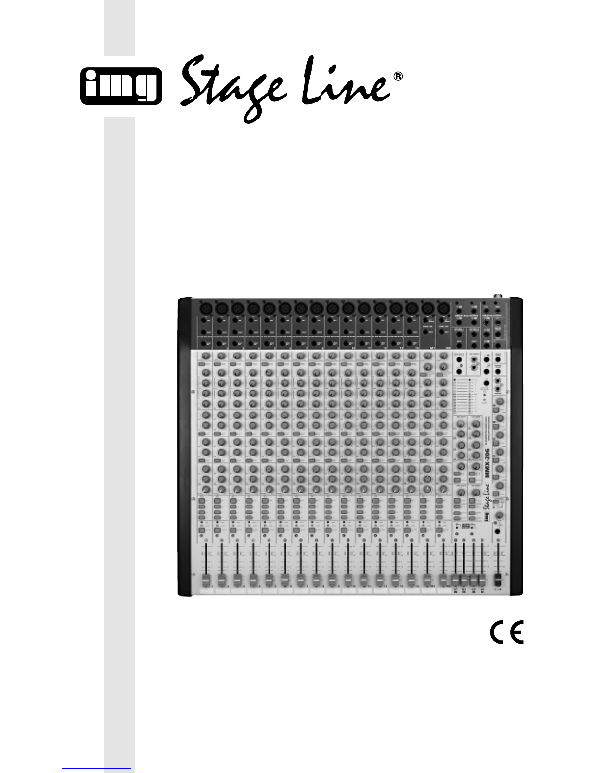
3.1 Mono-Kanalzüge 1 – 14
Die Mono-Eingangskanäle 1–14 sind identisch.
1 XLR-Buchse MIC (sym.) für den Anschluss eines
Mikrofons
Hinweis: Entweder ein Mikrofon an die XLRBuchse anschließen oder ein Gerät mit LinePegelausgang an die Klinkenbuchse LINE (2).
Hinweis: Die aktivierte Phantomspeisung kann
intern für einzelne Mono-Kanäle durch Entfernen
der Drahtbrücke LK1 abgeschaltet werden –
siehe dazu Kapitel 4.1.
2 6,3-mm-Klinkenbuchse LINE (sym.) für den An-
schluss eines Gerätes mit Line-Pegelausgang
Hinweis: Entwederein Gerät mit Line-Pegelausgang an die Klinkenbuchse anschließen oder
ein Mikrofon an die XLR-Buchse MIC (1).
3 Buchse INSERT zum Einschleifen eines Effekt-
gerätes (siehe Kapitel 5.6); Steckeranschlüsse:
Spitze = Send (Ausgang)
Ring = Return (Eingang)
Schaft = Masse
Vorsicht! Keine asymmetrischen Mikrofone
anschließen, wenn die Mikrofon-Phantomspeisung eingeschaltet ist: die gelbe LED PHANTOM POWER +48V (81) im Ausgangsfeld
leuchtet, siehe Abb. 4. Diese Mikrofone können
beschädigt werden.
4 Ausgangsbuchse DIRECT OUT (asym.) für
Mehrspuraufnahmen; hier liegt das bearbeitete
Kanalsignal nach dem Fader (24) an
5 Regler GAIN zum Einstellen der Eingangsver-
stärkung
6 Taste 100Hz zum Ein-/Ausschalten des 100-Hz-
Filters (Hochpass): unterdrückt unerwünschte
Signalanteile unter 100Hz, z.B. Brummen, Trittschall usw.
7 Klangregler HI (High) für die Höhen:
±15dB/12kHz
8 Regler zum Einstellen der Filterfrequenz (350Hz–
6kHz) für die Klangregelung im Mittenbereich
9 Klangregler MID für die Mitten:
±15dB/350Hz – 6 kHz
10 Klangregler LO (Low) für die Bässe:
±15 dB/ 60 Hz
11 Regler A1 und A2 zum Mischen des Kanalsig-
nals auf die Auskoppelwege A1 und A2
12 Umschalter für die Auskoppelwege A1 und A2
Taste gedrückt: das Kanalsignal wird vor dem
Fader ausgekoppelt (pre-fader)
nicht gedrückt: das Kanalsignal wird nach dem
Fader ausgekoppelt (post-fader)
13 Regler A3 und A4 zum Mischen des Kanalsig-
nals auf die Auskoppelwege A3 und A4
14 Umschalter für die Auskoppelwege A3 und A4
Taste gedrückt: das Kanalsignal wird vor dem
Fader ausgekoppelt (pre-fader)
Hinweis: Der Signalauskoppelpunkt kann intern durch Umstecken der Brücke JP2 für jeden
Kanal getrennt von pre-fader auf
pre-equalizer umgestellt werden,
siehe dazu Kapitel 4.3.
nicht gedrückt: das Kanalsignal wird nach dem
Fader ausgekoppelt (post-fader)
As the colours of the wires in the mains lead of this
appliance may not correspond with the coloured
markings identifying the terminals in your plug,
proceed as follows:
1.
The wire which is coloured green and yellow
must
be connected to the terminal in the plug
which is marked with the letter E or by the earth
symbol , or coloured green or green and yel-
low.
2. The wire which is coloured blue must be connected to the terminal which is marked with the
letter N or coloured black.
3. The wire which is coloured brown must be connected to the terminal which is marked with the
letter L or coloured red.
Warning – This appliance must be earthed.
3 Operating Elements and Connections
To obtain a better overview, the operating elements
and connections are numbered according to the
sections:
1–24 = mono channels 1 –14 including control
facilities
30–52 = stereo channels M1 and M2 including
control facilities
60–87 = output section
90–93 = rear side of mixer
95–98 = power supply unit
3.1 Mono channels 1 –14 including control
facilities
The mono input channels 1–14 are identical.
1 XLR jack MIC (bal.) for the connection of a
microphone
Note: Connect either a microphone to the XLR
jack or a unit with line level output to the 6.3mm
jack LINE (2).
Note: The activated phantom power can internally be switched off for individual mono channels
by removing the jumper LK1 – see chapter 4.1.
2 6.3 mm jack LINE (bal.) for the connection of a
unit with line level output
Note: Connect either a unit with line level output
to the 6.3 mm jack or a microphone to the XLR
jack MIC (1).
3 Jack INSERT for inserting an effect unit (see
chapter 5.6); plug connections:
tip = Send (output)
ring = Return (input)
body = ground
4 Output jack DIRECT OUT (unbal.) for multi-track
recordings; in this case the processed channel
signal is present after the fader (24)
5 Control GAIN for adjusting the input amplification
6 Button 100Hz for switching on/off the 100Hz fil-
ter (high pass): suppresses unwanted signal
parts below 100Hz, e.g. hum, rumble, etc.
7 Equalizer control HI (High) for the high frequen-
cies: ±15dB/12kHz
8 Control for adjusting the filter frequency
(350Hz–6kHz) for the equalizer in the
midrange
9 Equalizer control MID for the midrange:
±15dB/350 Hz– 6 kHz
10 Equalizer control LO (Low) for the bass frequen-
cies: ±15dB/60Hz
11 Controls A1 and A2 for adding the channel signal
to the AUX send ways A1 and A2
Attention! Do not connect any unbalanced
microphones if the microphone phantom power
is switched on: the yellow LED PHANTOM
POWER +48 V (81) in the output section lights
up, see fig. 4. These microphones may be
damaged.
LR
010
010
010
010
010
010
–+
–+
350
–+
450
1k
1k8
2k5
5k
6kHz
12 60dB
100Hz
40
15
20
PFL/SOLO
1
SIGNAL
PEAK
3–4
1–2
L–R
MUTE
1
PAN
A6
A5
A4
A3
A2
A1
LO
MID
HI
1
LINE
MIC
INSERT
DIRECT
OUT
1
(TIP: SEND RING: RETURN)
30
GAIN
POST
PRE
POST
PRE
∞
–10
–5
0dB
+5
+10
1
2
3
4
5
6
7
8
9
10
11
12
14
16
17
18
19
20
21
22
23
24
13
15
Mono-Kanalzug 1
Mono channel 1 with control facilities
Fig. 1
6
15 Regler A5 und A6 zum Mischen des Kanalsig-
nals auf die Auskoppelwege A5 und A6
Hinweis: Das Signal wird vor dem Fader ausgekoppelt (pre-fader), kann jedoch intern durch
Umstecken der Brücke JP1 für jeden Kanal getrennt post-fader oder pre-equalizer abgenommen werden – siehe dazu Kapitel 4.3
16 Panoramaregler PAN zum Platzieren des Mono-
Kanalsignals in der Stereo-Basis
17 Taste MUTE zum Stummschalten des Kanals;
bei stummgeschaltetem Kanal leuchtet die darüber liegende gelbe LED
18 Routingtaste L-R: ist diese Taste gedrückt, wird
der Kanal auf die Ausgangssumme L-R gemischt
19 Routingtaste 1-2: ist diese Taste gedrückt, wird
der Kanal abhängig vom Panoramareglers PAN
(16) auf die Subgruppen G1 und G2 gemischt:
PAN in Pos. „L“: nur auf G1
PAN in Mittelpos.: gleichmäßig auf G1 und G2
PAN in Pos. „R“: nur auf G2
20 Routingtaste 3-4: ist diese Taste gedrückt, wird
der Kanal abhängig vom Panoramareglers PAN
(16) auf die Subgruppen G3 und G4 gemischt:
PAN in Pos. „L“: nur auf G3
PAN in Mittelpos.: gleichmäßig auf G3 und G4
PAN in Pos. „R“: nur auf G4
21 Übersteuerungsanzeige PEAK
kurzes Aufleuchten:
der Kanalzug ist maximal ausgesteuert und
wird gerade noch nicht übersteuert
leuchtet permanent:
der Kanal wird übersteuert; den Pegel mit dem
Kanalfader (24) und/oder mit dem Regler
GAIN (5) niedriger einstellen
22 Anzeige SIGNAL: leuchtet, wenn ein Eingangs-
signal anliegt (pre-fader, ab
-
20dB)
23 Taste PFL/SOLO
entweder zum Vorhören des Kanals (PFL = „Pre
Fader Listening”) über einen an der Buchse
PHONES angeschlossenen Kopfhörer und über
eine an der Buchse CONTROL ROOM angeschlossene Monitoranlage;
gleichzeitig wird die Aussteuerungsanzeige auf
den zum Vorhören gewählten Kanal geschaltet
oder zur Kontrolle der gesamten Kanaleinstellung nach dem Fader (SOLO)
Die Umschaltung zwischen PFL und SOLO erfolgt mit der Taste LISTEN MODE im Ausgangsfeld, siehe auch Position 84
24 Kanalfader zum Einstellen des Pegels, mit dem
das Kanalsignal auf den angewählten Weg (L-R,
1-2, 3-4) gemischt wird
12 Selector switch for the AUX send ways A1 and A2
button pressed: the channel signal is taken off
ahead of the fader (pre fader)
not pressed: the channel signal is taken off
after the fader (post fader)
13 Controls A3 and A4 for adding the channel signal
to the AUX send ways A3 and A4
14 Selector switch for the AUX send ways A3 and A4
button pressed: the channel signal is taken off
ahead of the fader (pre fader)
Note: The signal take-off point
can internally be changed by
rearranging the jumper JP2
separately for each channel
from pre fader to pre equalizer,
see chapter 4.3.
not pressed: the channel signal is taken off
after the fader (post fader)
15 Controls A5 and A6 for adding the channel signal
to the AUX send ways A5 and A6
Note: The signal is taken off ahead of the fader
(pre fader) but it can internally be taken off post
fader or pre equalizer by rearranging the jumper
JP1 separately for each channel, see chapter 4.3
16 Panorama control PAN for placing the mono
channel signal in the stereo base
17 Button MUTE for muting the channel;
if the channel is muted, the yellow LED above
the button lights up
18 Routing button L-R: if this button is pressed, the
channel is added to the master output L-R
19 Routing button 1-2: if this button is pressed, the
channel is added to the subgroups G1 and G2
depending on the panorama control PAN (16):
PAN in position “L”: only to G1
PAN in mid-position: equally to G1 and G2
PAN in position “R”: only to G2
20 Routing button 3-4: if this button is pressed, the
channel is added to the subgroups G3 and G4
depending on the panorama control PAN (16):
PAN in position “L”: only to G3
PAN in mid-position: equally to G3 and G4
PAN in position “R”: only to G4
21 Overload indication PEAK
short lighting-up:
the maximum output level of the channel is
obtained, the channel is just not yet overloaded
permanent lighting:
the channel is overloaded: reduce the level
with the channel fader (24) and/or the control
GAIN (5)
22 Indication SIGNAL: lights up if an input signal is
present (pre fader, as from
-
20dB)
23 Button PFL/SOLO
either for pre fader listening (PFL) of the channel
via headphones connected to the jack PHONES
and via a monitoring system connected to the
jack CONTROL ROOM;
at the same time the level display is switched to
the channel selected for pre fader listening
or for checking the complete channel adjustment
after the fader (SOLO)
PFL and SOLO are switched over with button
LISTEN MODE in the output section, also see
position 84
24 Channel fader for adjusting the level with which
the channel signal is added to the selected way
(L-R, 1-2, 3-4)
LR
010
010
010
010
010
010
–+
–+
350
–+
450
1k
1k8
2k5
5k
6kHz
12 60dB
100Hz
40
15
20
PFL/SOLO
1
SIGNAL
PEAK
3–4
1–2
L–R
MUTE
1
PAN
A6
A5
A4
A3
A2
A1
LO
MID
HI
1
LINE
MIC
INSERT
DIRECT
OUT
1
(TIP: SEND RING: RETURN)
30
GAIN
POST
PRE
POST
PRE
∞
–10
–5
0dB
+5
+10
1
2
3
4
5
6
7
8
9
10
11
12
14
16
17
18
19
20
21
22
23
24
13
15
Mono-Kanalzug 1
Mono channel 1 with control facilities
Fig. 2
7
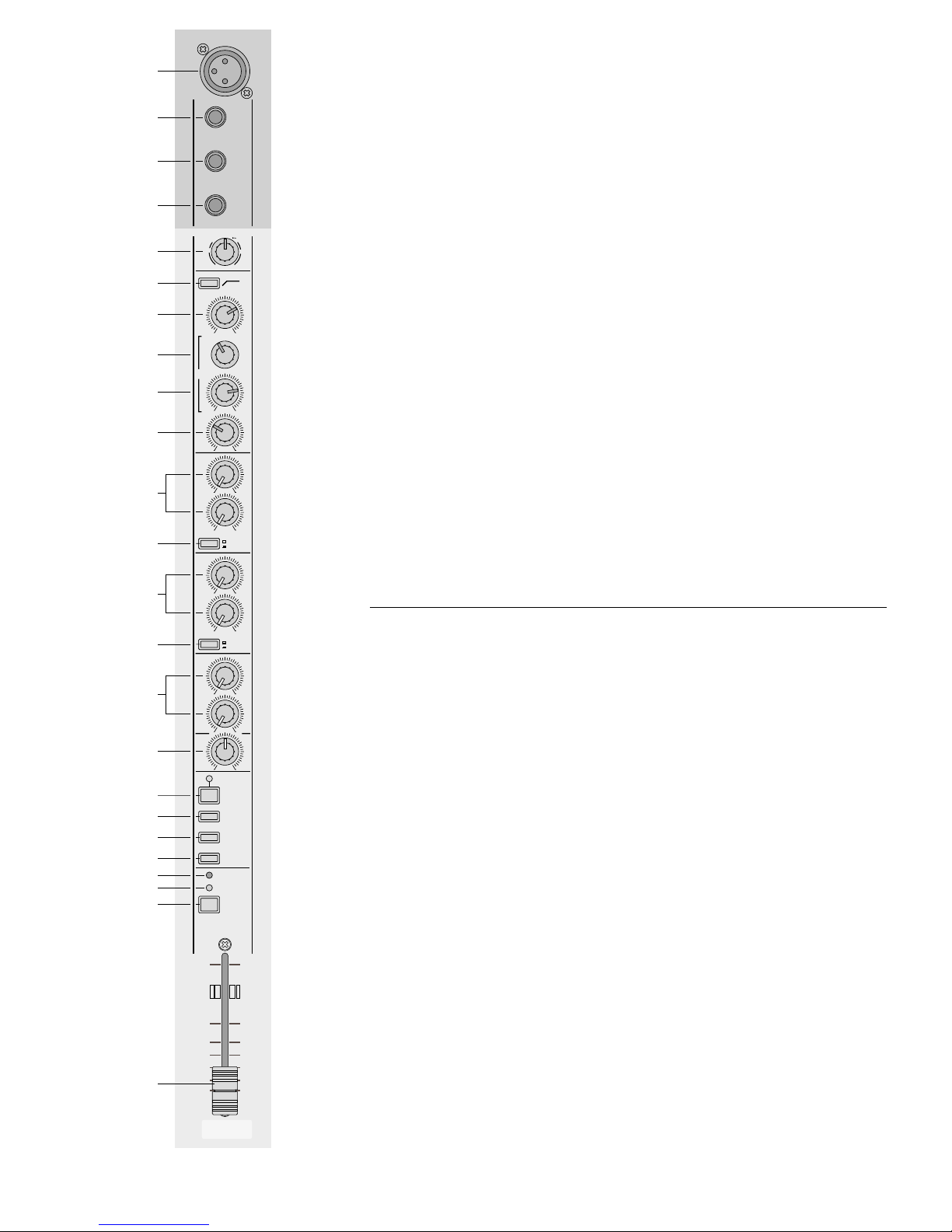
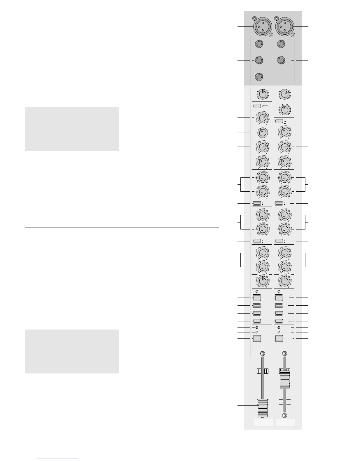
3.2 Stereo-Kanalzüge M1 und M2
Die Stereo-Eingangskanäle M1 und M2 sind identisch. Weil die Bedienelemente 39 bis 52 denen der
in den Mono-Kanalzügen ähneln, werden sie hier
nur kurz erklärt.
30 XLR-Buchse MIC (sym.) für den Anschluss eines
Mikrofons (für phantomgespeiste Mikrofone
nach Kapitel 4.2 die Brücke LK1 einlöten)
Hinweis: Entweder ein Mikrofon an die XLRBuchse anschließen oder ein Gerät mit LinePegelausgang an die Klinkenbuchsen STEREO
LINE (31 und 32).
31 6,3-mm-Klinkenbuchse LEFT (sym.) für den An-
schluss des linken Kanals eines Gerätes mit
Line-Pegelausgang
Hinweis: Bei Monogeräten nur diese Buchse
anschließen. Das Signal wird dann intern auf
den rechten und linken Kanal geschaltet.
32 6,3-mm-Klinkenbuchse RIGHT (sym.) für den
Anschluss des rechten Kanals eines Gerätes mit
Line-Pegelausgang
33 Regler GAIN MIC zum Einstellen der Eingangs-
verstärkung für das Signal der Buchse MIC (30)
34 Regler GAIN LINE zum Einstellen der Ein-
gangsverstärkung für das Signal der Buchsen
STEREO LINE (31 und 32)
35 Zuordnungsschalter EQ ASSIGN für die Klang-
regler HI, MID und LO (36–38)
Taste gedrückt: die Klangregler wirken auf das
Signal von den Klinkenbuchsen
STEREO LINE (31, 32)
nicht gedrückt: die Klangregler wirken auf das
Signal von der XLR-Buchse MIC
(30)
36 Klangregler HI (High) für die Höhen:
±15dB/12kHz
37 Klangregler MID für die Mitten:
±15dB/1,5kHz
38 Klangregler LO (Low) für die Bässe:
±15 dB/ 60 Hz
39 Regler A1 und A2 zum Mischen des Kanalsig-
nals auf die Auskoppelwege A1 und A2
40 Umschalter post-fader/ pre-fader für die Auskop-
pelwege A1 und A2
41 Regler A3 und A4 zum Mischen des Kanalsig-
nals auf die Auskoppelwege A3 und A4
42 Umschalter post-fader/ pre-fader für die Auskop-
pelwege A3 und A4
43 Regler A5 und A6 zum Mischen des Kanalsig-
nals auf die Auskoppelwege A5 und A6
44 Balanceregler BAL; ist nur die Buchse LEFT (31)
angeschlossen oder nur die Buchse MIC (30),
arbeitet er als Panoramaregler
45 Taste MUTE zum Stummschalten des Kanals
46 Routingtaste L-R: ist diese Taste gedrückt, wird
der Kanal auf die Ausgangssumme L-R gemischt
47 Routingtaste 1-2: ist diese Taste gedrückt, wird
der Kanal auf die Subgruppen G1 und G2 gemischt
48 Routingtaste 3-4: ist diese Taste gedrückt, wird
der Kanal auf die Subgruppen G3 und G4 gemischt
49 Übersteuerungsanzeige PEAK
50 Anzeige SIGNAL: leuchtet, wenn ein Eingangs-
signal anliegt (pre-fader, ab
-
20dB)
51 Taste PFL/SOLO zum Vorhören des Kanals
(PFL) oder zur Kontrolle der gesamten Kanaleinstellung nach dem Fader (SOLO),
– siehe auch Position 84
52 Kanalfader
3.2 Stereo channels M1 and M2 including
control facilities
The stereo input channels M1 and M2 are identical.
As the operating elements 39 to 52 are similar to
those of the mono channels, they are explained only
shortly in this place.
30 XLR jack MIC (bal.) for connection of a micro-
phone (for phantom-powered microphones according to channel 4.2, solder in the jumper LK1)
Note: Connect either a microphone to the XLR
jack or a unit with line level output to the 6.3mm
jacks STEREO LINE (31 and 32)
31 6.3mm jack LEFT (bal.) for the connection of the
left channel of a unit with line level output
Note: In case of mono units only connect this
jack. Then the signal is internally switched to the
right and left channels.
32 6.3 mm jack RIGHT (bal.) for the connection of
the right channel of a unit with line level output
33 Control GAIN MIC for adjusting the input amplifi-
cation for the signal of the jack MIC (30)
34 Control GAIN LINE for adjusting the input ampli-
fication for the signal of the jacks STEREO LINE
(31 and 32)
35 Assign switch EQ ASSIGN for the equalizer con-
trols HI, MID, and LO (36–38)
button pressed: the equalizer controls influence
the signal of the 6.3 mm jacks
STEREO LINE (31, 32)
not pressed: the equalizer controls influence
the signal of the XLR jack MIC
(30)
36 Equalizer control HI (High) for the high range:
±15dB/12kHz
37 Equalizer control MID for the midrange:
±15dB/1.5kHz
38 Equalizer control LO (Low) for the bass range:
±15 dB/ 60 Hz
39 Controls A1 and A2 for adding the channel signal
to the AUX send ways A1 and A2
40 Selector switch post fader/pre fader for the AUX
send ways A1 and A2
41 Controls A3 and A4 for adding the channel signal
to the AUX send ways A3 and A4
42 Selector switch post fader/pre fader for the AUX
send ways A3 and A4
43 Controls A5 and A6 for adding the channel signal
to the AUX send ways A5 and A6
44 Balance control BAL; if only jack LEFT (31) or
only jack MIC (30) is connected, it operates as a
panorama control
45 Button MUTE for muting the channel
46 Routing button L-R: if this button is pressed, the
channel is added to the master output L-R
47 Routing button 1-2: if this button is pressed, the
channel is added to the subgroups G1 and G2
48 Routing button 3-4: if this button is pressed, the
channel is added to the subgroups G3 and G4
49 Overload indication PEAK
50 Indication SIGNAL: lights up if an input signal is
present (pre fader, as from
-
20 dB)
51 Button PFL/SOLO for pre fader listening (PFL) of
the channel or for checking the complete channel
adjustment after the fader (SOLO),– also see
position 84
52 Channel fader
SIGNAL
PEAK
3–4
1–2
L–R
MUTE
M1
BAL
30
31
32
33
35
36
37
38
44
45
46
47
48
49
50
51
LEFT
(MONO)
MIC
RIGHT
M1
STEREO LINE
LR
010
010
010
010
010
010
PFL/SOLO
M1
M1
–+
LO
–+
MID
–+
HI
A6
A5
A4
A3
A2
A1
12 60dB
40
15
20
30
0 +20dB
+5
+15
+10
MIC
LINE
EQ ASSIGN
POST
PRE
POST
PRE
MIC
LINE
∞
–10
–5
0dB
+5
+10
34
39
40
42
52
GAIN
41
43
Stereo-Kanalzug M1
Stereo channel M1 with control facilities
Fig. 3
8
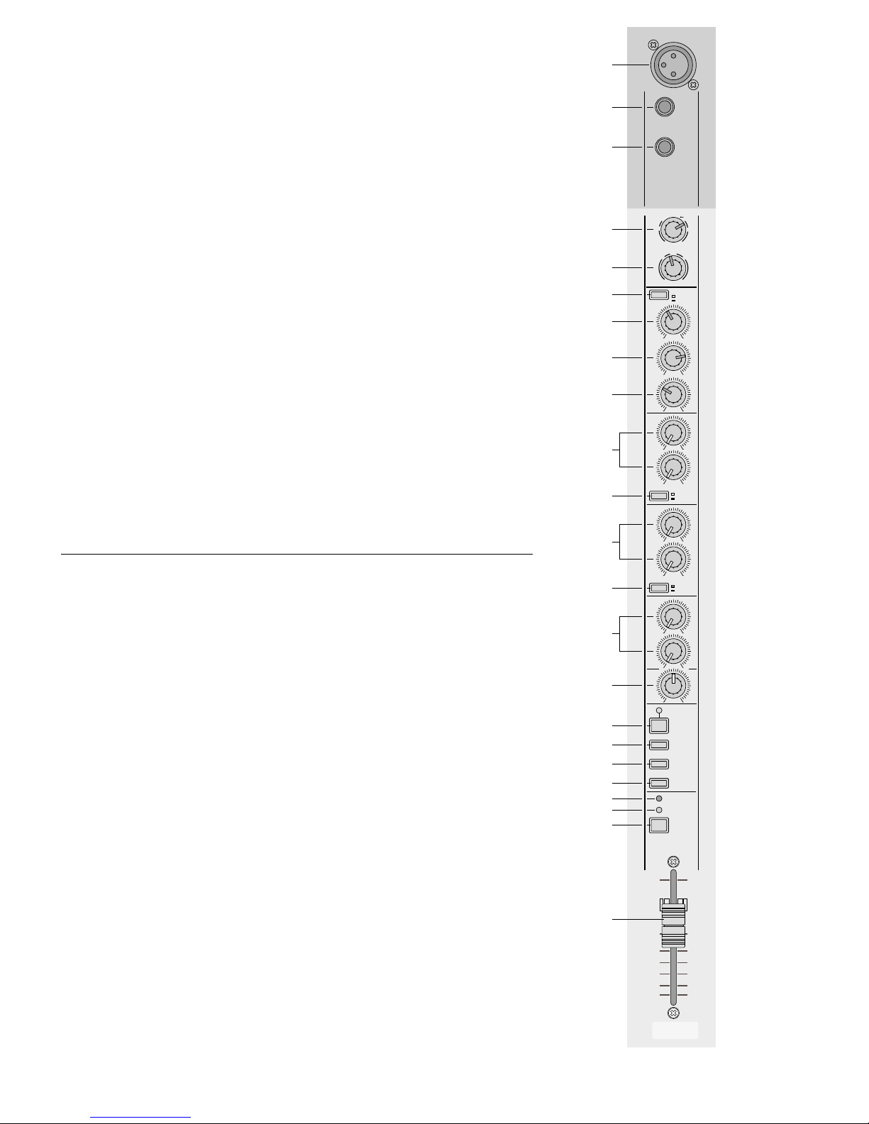
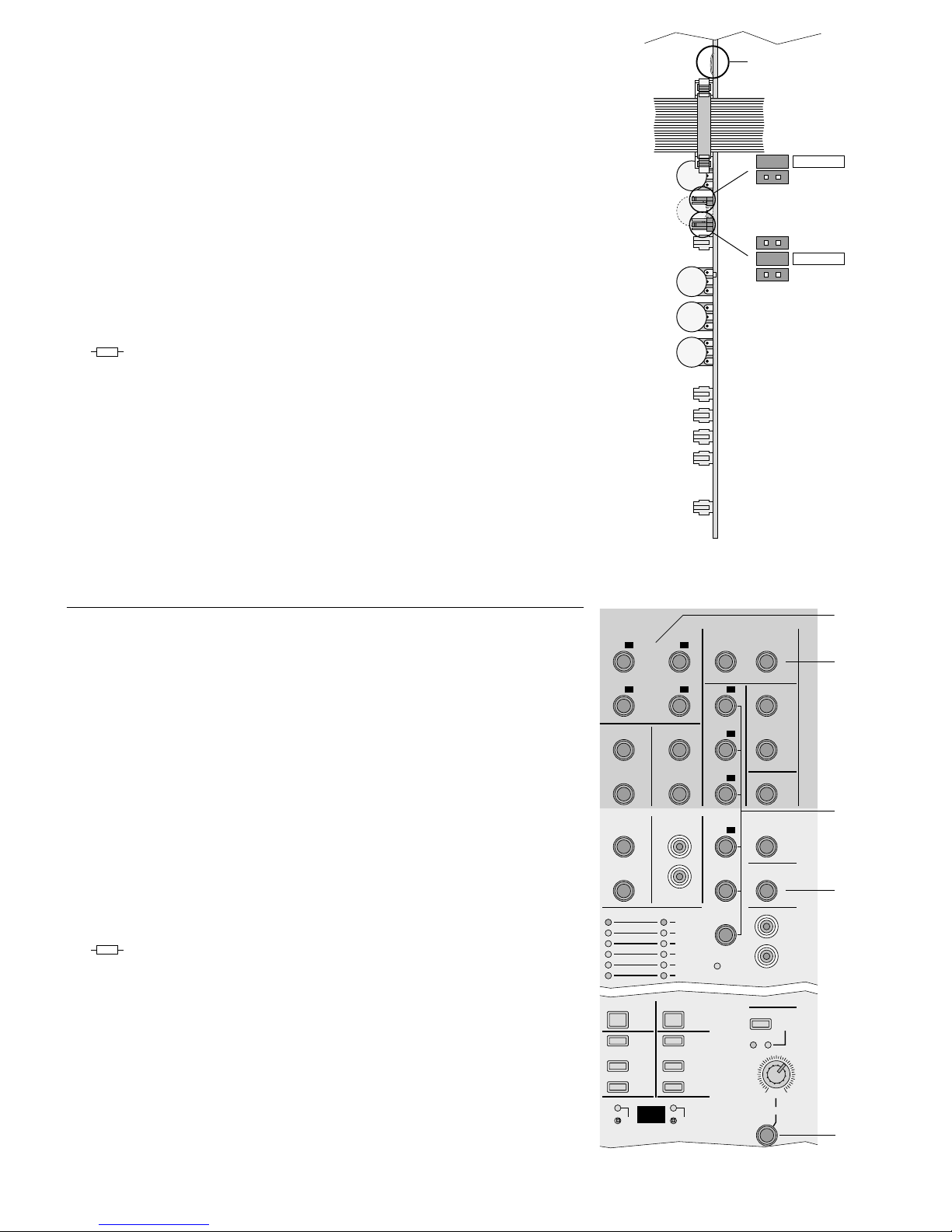
3.3 Ausgangsfeld
60 Ausgänge (asym.) der Subgruppen oder Aus-
koppelwege
im Normal-Modus
[die LEDs STAGE MODE (73) leuchten nicht]:
Ausgänge für die Subgruppen G1 bis G4
im Stage-Modus
[Schalter STAGE MODE „1-2“ und/ oder „3-4“
(73) gedrückt, LEDs darüber leuchten]:
Ausgänge für die Auskoppelwege A1 bis A4
(die Bedruckung bis ist jetzt maßgebend)
61 Stereo-Zusatzeingänge AUX INPUT 1 bis 4;
AUX 1–3: sym., AUX 4: asym.
62 Aussteuerungsanzeige (Spitzenwertanzeige):
a) wenn keine der Tasten PFL/SOLO (68, 70,
72, 83 oder in den Eingangskanälen) gedrückt
ist, wird der Pegel der Ausgangssumme L-R
post-fader angezeigt
b) wenn eine oder mehrere Tasten PFL/ SOLO
gedrückt sind, wird der zugehörige Pegel der
angewählten Kanäle, Subgruppen oder Auskoppelwege pre- oder post-fader angezeigt
– siehe Position 84
63 Betriebsanzeige POWER
64 Klangregler HI (Höhen: ±12 dB /11 kHz) und LO
(Tiefen: ±12dB/70Hz) für die Eingänge AUX
INPUT 1 und 2 (61)
65 Regler A5 und A6 für die Eingänge AUX INPUT1
und 2 zum Mischen der Signale (pre-fader) auf
die Auskoppelwege A5 und A6
66 Regler LEVEL für den Pegel der Eingänge AUX
INPUT 1 und 2
67 Routingtasten der Eingänge AUX INPUT1 und 2
Taste gedrückt: Eingang AUX INPUT 1 wird auf
die Subgruppen G1 und G2 gemischt bzw. AUX INPUT 2 auf
G3 und G4
A4A1
3.3 Output section
60 Outputs (unbal.) of the subgroups or AUX send
ways
in normal mode
[the LEDs STAGE MODE (73) do not light up]:
outputs for the subgroups G1 to G4
in the stage mode
[switch STAGE MODE “1-2” and/ or “3-4” (73)
pressed, LEDs above them light up]:
outputs for the AUX send ways A1 to A4 (the
printings to are relevant now)
61 Additional stereo inputs AUX INPUT 1 to 4;
AUX 1–3: bal., AUX 4: unbal.
62 Level display (peak value display):
a) if none of the buttons PFL/SOLO (68, 70, 72,
83 or in the input channels) is pressed, the
level of the master output L-R is displayed
post fader
b) if one or several buttons PFL/SOLO are
pressed, the corresponding level of the selected channels, subgroups, or AUX send
ways is displayed pre fader or post fader – see
position 84
63 POWER LED
64 Equalizer controls HI (high frequencies: ±12dB /
11 kHz) and LO (low frequencies: ±12dB/70Hz)
for the inputs AUX INPUT1 and 2 (61)
65 Controls A5 and A6 for the inputs AUX INPUT 1
and 2 for adding the signals (pre fader) to the
AUX send ways A5 and A6
66 Controls LEVEL for the level of the inputs AUX
INPUT 1 and 2
67 Routing buttons of the inputs AUX INPUT1 and 2
button pressed: AUX INPUT 1 is added to the
subgroups G1 and G2 or AUX
INPUT 2 to G3 and G4
not pressed: the corresponding input is
added to the master output L-R
A4A1
60
G1 A1
G2
A2
G3
A3
G4
A4
GROUP/ AUX OUTPUT
LEFT RIGHT
A1
G1 LEFT
A2
G2
RIGHT
A3
G3
MASTER OUTPUT
(TIP: SEND RING: RETURN)
MASTER
INSERT
AUX INPUT 1
LEFT (MONO)
AUX INPUT 2
LEFT (MONO)
RIGHT RIGHT
G1
RIGHT
A4
G4
G2
A5
AUX INPUT 3
LEFT (MONO)
AUX INPUT 4
L
R
GROUP
INSERT
(TIP: SEND RING: RETURN)
A6
CONTROL
ROOM
TAPE REC
L
R
PHANTOM
POWER +48V
POWER
LEFT RIGHT
+15
12
9
6
3
0dB
3
6
9
12
15
-20
010
PFL/SOLO
A1
G1
010
PFL/SOLO
A2
G2
010
PFL/SOLO
A3
G3
010
PFL/SOLO
A4
010
PFL/SOLO
A5
010
PFL/SOLO
A6
∞
–10
–5
0dB
+5
+10
∞
–10
–5
0dB
+5
+10
G1 G2 G3 G4
A1 A2 A3 A4
L – R
PHONES
010
LEVEL
CR/ PHONES
PFL SOLO
LISTEN
MODE
PFL/SOLO
G1
1–2
TO L– R
PFL/SOLO
PFL/SOLO
G2
010
PFL/SOLO
L–R
1–2
010
010
–+
010
–+
AUX INPUT 1
LO
HI
A5
A6
LEVEL
AUX INPUT 3
PFL/SOLO
G3
3–4
TO L–R
PFL/SOLO
PFL/SOLO
G4
010
PFL/SOLO
L–R
3–4
010
010
–+
010
–+
AUX INPUT 2
LO
HI
A5
A6
LEVEL
AUX INPUT 4
1–2 3–4
STAGE
MODE
MMX-206
16 CHANNEL PRO AUDIO MIXER
ULTRA LOW NOISE DESIGN
G4
75
76
61 77
79
78
62
80
82
83
81
63
64
65
66
68
67
69
70
71
72
73
74
84
85
86
87
Ausgangsfeld
Output section
Fig. 4

9
nicht gedrückt: der entsprechende Eingang wird
auf die Ausgangssumme L-R
gemischt
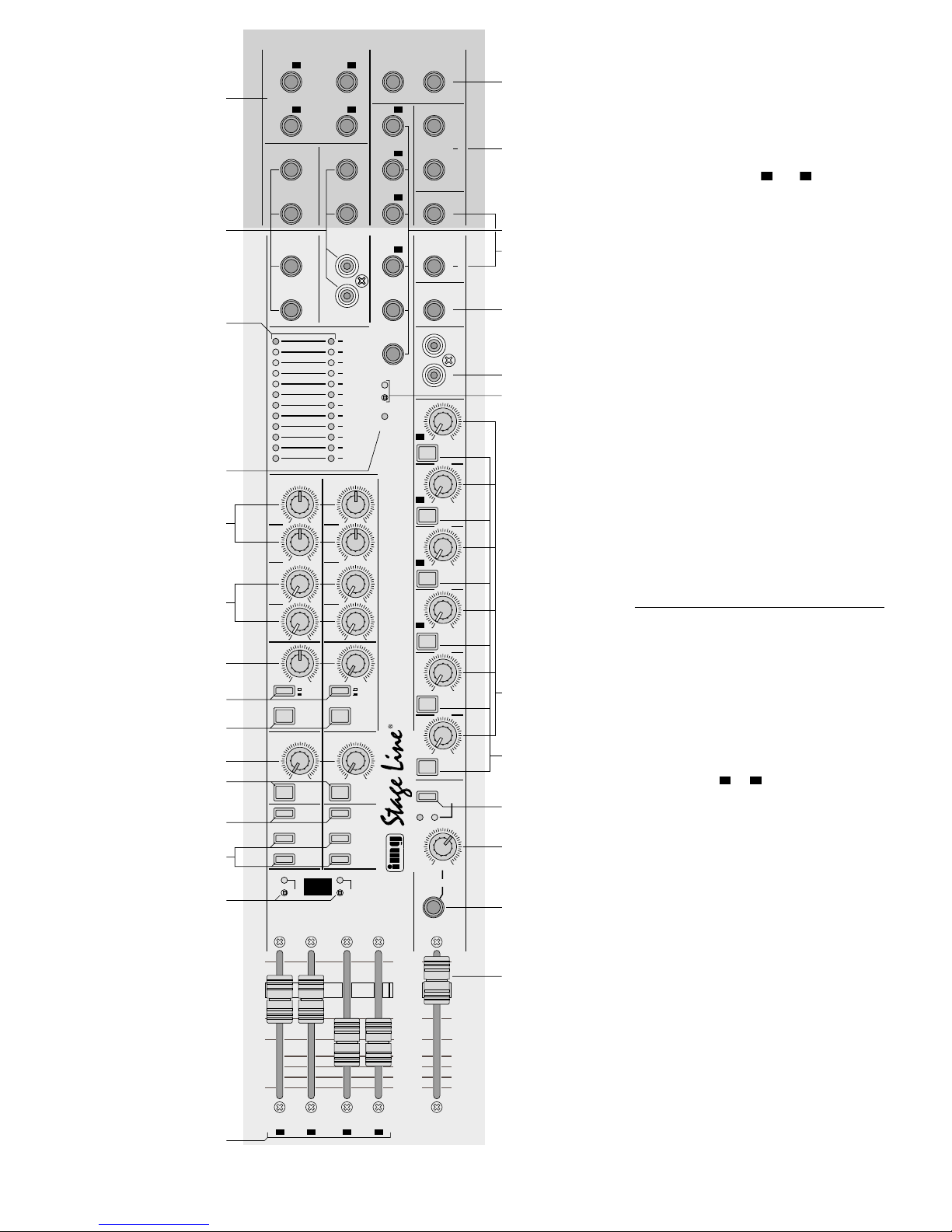
68 Tasten PFL /SOLO zum Vorhören des Eingangs
AUX INPUT 1 bzw. 2 [PFL] oder zur Kontrolle der
gesamten Kanaleinstellung nach dem Pegelregler
(66) [SOLO] – siehe auch Position 84
69 Regler AUX INPUT 3 und 4 für den Pegel der
Eingänge AUX INPUT 3 und 4 zum Mischen auf
die Ausgangssumme L-R
70 Tasten PFL /SOLO zum Vorhören des Eingangs
AUX INPUT 3 bzw.4 [PFL] oder zur Kontrolle der
Pegeleinstellung nach dem Pegelregler (69)
[SOLO] – siehe auch Position 84
71 Routingtasten für die Subgruppen G1 und G2
sowie G3 und G4: bei gedrückter Taste wird die
entsprechende Gruppe auf die Ausgangssumme
L-R gemischt*
72 Tasten PFL / SOLO zum Vorhören der Subgrup-
pen G1 bis G4 [PFL] oder zur Kontrolle nach den
Fadern (74) [SOLO]* – siehe auch Position 84
73 versenkte Tasten mit darüberliegender Kontroll-
LED zum Einschalten des Stage-Modus; bei diesem Modus sind die Summenpegel für die Auskoppelwege A1 bis A4 mit den Fadern G1 bis G4
(74) regelbar, d.h.:
1. Die Fader der Subgruppen G1 bis G4 (74)
sind mit den Pegelreglern (82) für die Auskoppelwege A1 bis A4 vertauscht.
2. Die dazugehörigen Ausgangsbuchsen G1 bis
G4 (60) sind mit den Ausgangsbuchsen A1 bis
A4 (77) vertauscht.
3. Die Summensignale der Auskoppelwege A1
bis A4 können mit der Taste 1-2 TO L-R (71)
bzw. mit der Taste 3-4 TO L-R (71) auf die
Ausgangssumme geschaltet werden.
Die zugehörige grüne LED leuchtet und die
Bedruckungen bis und bis sind
jetzt maßgebend.
74 Fader für die Pegel der Subgruppen G1 bis G4*
G4G1A4A1
75 Buchsen MASTER OUTPUT (sym.) für die Aus-
gangssumme L-R; parallel geschaltet mit den
XLR-Buchsen LEFT und RIGHT auf der Rückseite
76 Buchsen MASTER INSERT zum Einschleifen
eines Effektgerätes in die Ausgangssumme L-R
(siehe auch Kapitel 5.6); Steckeranschlüsse:
Spitze = Send (Ausgang)
Ring = Return (Eingang)
Schaft = Masse
77 Buchsen (asym.) für die Auskoppelwege A1–A6*
78 Buchsen GROUP INSERT zum Einschleifen
eines Effektgerätes in die Subgruppen G1 und
G2 (siehe Kapitel 5.6); Steckeranschlüsse:
Spitze = Send (Ausgang)
Ring = Return (Eingang)
Schaft = Masse
79 Ausgangsbuchse CONTROL ROOM für den
Anschluss einer Monitoranlage in einem separaten (Regie-) Raum;
Ausgangssignal siehe Position 84;
Steckeranschlüsse:
Spitze = linker Kanal
Ring = rechter Kanal
Schaft = Masse
80 Cinch-Ausgangsbuchsen TAPE REC (asym.)
zum Anschluss eines Aufnahmegerätes: hier
liegt die Ausgangssumme L-R an (post-fader)
81 versenkter Schalter (mit gelber Kontroll-LED) zum
zentralen Zuschalten der 48-V-Phantomspeisung
für die XLR-Buchsen MIC der Mono-Eingangskanäle 1 –14; erforderlich beim Anschluss von
Kondensator- oder Elektretmikrofonen, die mit
48-V-Phantomspeisung arbeiten
Achtung! Bei anliegender Phantomspannung
dürfen an den Mikrofoneingängen der MonoKanalzüge keine asymmetrischen Mikrofone
angeschlossen sein, da diese zerstört werden
könnten. Zum Abschalten der Phantomspeisung einzelner Kanäle siehe Kapitel 4.1.
82 Summenregler für die Auskoppelwege A1 bis A6*
83 Tasten PFL / SOLO zur Kontrolle der Signale an
den Buchsen A1 bis A6 (77)
84 Taste LISTEN MODE für die Buchsen PHONES
(86) und CONTROL ROOM (79)
Taste gedrückt Die gelbe LED SOLO leuchtet:
Es lässt sich die Ausgangssumme L-R kontrollieren (postfader) oder
die gelbe LED blinkt (sobald eine
PFL/ SOLO-Taste gedrückt ist):
es lässt sich der Kanal, die Subgruppe oder der Auskoppelweg
kontrollieren (post-fader), dessen
PFL/SOLO-Taste gedrückt ist.
nicht gedrückt Die grüne LED PFL leuchtet:
es lässt sich die Ausgangssumme L-R kontrollieren (postfader) oder
die grüne LED blinkt (sobald eine
PFL/ SOLO-Taste gedrückt ist):
es lässt sich der Kanal, die Subgruppe oder der Auskoppelweg
vorhören (pre-fader), dessen
PFL/SOLO-Taste gedrückt ist
85 Lautstärkeregler LEVEL für einen an der Buchse
PHONES (86) angeschlossenen Kopfhörer und
für die Buchse CONTROL ROOM (79)
86 6,3-mm-Klinkenbuchse PHONES zum Anschluss
eines Stereo-Kopfhörers (Impedanz ≥ 32Ω);
Ausgangssignal siehe Position 84
87 Fader für den Pegel der Ausgangssumme L-R;
die Ausgangssumme liegt an den XLR-Buchsen
auf der Rückseite an und an der Buchse TAPE
REC (80)
*im Normal-Modus, für den Stage-Modus siehe Position 73
68 Buttons PFL/SOLO for pre fader listening of the
input AUX INPUT1 or 2 [PFL] or for checking the
complete channel adjustment after the level control (66) [SOLO] – also see position 84
69 Controls AUX INPUT 3 and 4 for the level of the
inputs AUX INPUT 3 and 4 for adding to the
master output L-R
70 Buttons PFL/SOLO for pre fader listening of the
input AUX INPUT3 or 4 [PFL] or for checking the
level adjustment after the level control (69)
[SOLO] – also see position 84
71 Routing buttons for the subgroups G1 and G2 as
well as G3 and G4: with the button pressed, the
corresponding group is added to the master output L-R*
72 Buttons PFL/SOLO for pre fader listening of the
subgroups G1 to G4 [PFL] or for checking after
the faders (74) [SOLO]* – also see position 84
73 Recessed buttons with indicating LED above
them for switching on the stage mode; with this
mode the master levels for the AUX send ways
A1 to A4 can be adjusted with the faders G1 to
G4 (74), i.e.:
1. The faders of the subgroups G1 to G4 (74) are
exchanged with the level controls (82) for the
AUX send ways A1 to A4.
2. The corresponding output jacks G1 to G4 (60)
are exchanged with the output jacks A1 to A4
(77).
3. The master signals of the AUX send ways A1
to A4 can be switched to the master output
with the button 1-2 TO L-R (71) or with the button 3-4 TO L-R (71)
The corresponding green LED lights up and the
printings to and to are relevant
now.
74 Faders for the levels of the subgroups G1 to G4*
75 Jacks MASTER OUTPUT (bal.) for the master
output L-R; connected in parallel with the XLR
jacks LEFT and RIGHT on the rear side
G4G1A4A1
76 Jacks MASTER INSERT for inserting an effect
unit into the master output L-R (also see chapter
5.6); plug connections:
tip = Send (output)
ring = Return (input)
body = ground
77 Jacks (unbal.) for the AUX send ways A1 to A6*
78 Jacks GROUP INSERT for inserting an effect
unit into the subgroups G1 and G2 (see chapter
5.6); plug connections:
tip = Send (output)
ring = Return (input)
body = ground
79 Output jack CONTROL ROOM for the connec-
tion of a monitoring system in a separate (control) room;
output signal see item 84;
plug connections:
tip = left channel
ring = right channel
body = ground
80 Phono output jacks TAPE REC (unbal.) for
connection of a recording unit: the master output
L-R is present at these jacks (post fader)
81 Recessed switch (with yellow indicating LED) for
central switching of the 48V phantom power for
the XLR jacks MIC of the mono input channels 1
to 14; necessary when connecting capacitor or
electret microphones which operate with 48 V
phantom power
82 Master control for the AUX send ways A1 to A6*
83 Buttons PFL/ SOLO for checking the signals at
the jacks A1 to A6 (77)
Attention! With applied phantom voltage no
unbalanced microphones must be connected to
the microphone inputs of the mono channels as
these microphones may be destroyed. T o switch
off the phantom power of individual channels,
see chapter 4.1.
84 Button LISTEN MODE for the jacks PHONES
(86) and CONTROL ROOM (79)
button pressed the yellow LED SOLO lights up:
it is possible to check the master
output L-R (post fader) or
the yellow LED flashes (as
soon as a PFL/ SOLO button is
pressed):
it is possible to check the
channel, the subgroup, or the
AUX send way (post fader), of
which the PFL/ SOLO button is
pressed.
not pressed the green LED PFL lights up:
it is possible to check the master
output L-R (post fader) or
the green LED flashes (as
soon as a PFL/ SOLO button is
pressed):
it is possible to pre fader listen to
the channel, the subgroup, or
the AUX send way, of which the
PFL/SOLO button is pressed
85 Volume control LEVELfor headphones connect-
ed to the jack PHONES (86) and for the jack
CONTROL ROOM (79)
86 6.3 mm jack PHONES for connection of stereo
headphones (impedance ≥ 32Ω);
for the output signal see position 84
87 Fader for the level of the master output L-R;
the master output is present at the XLR jacks on
the rear side and at the jack TAPE REC (80)
*in the normal mode, for the stage mode see position 73
10
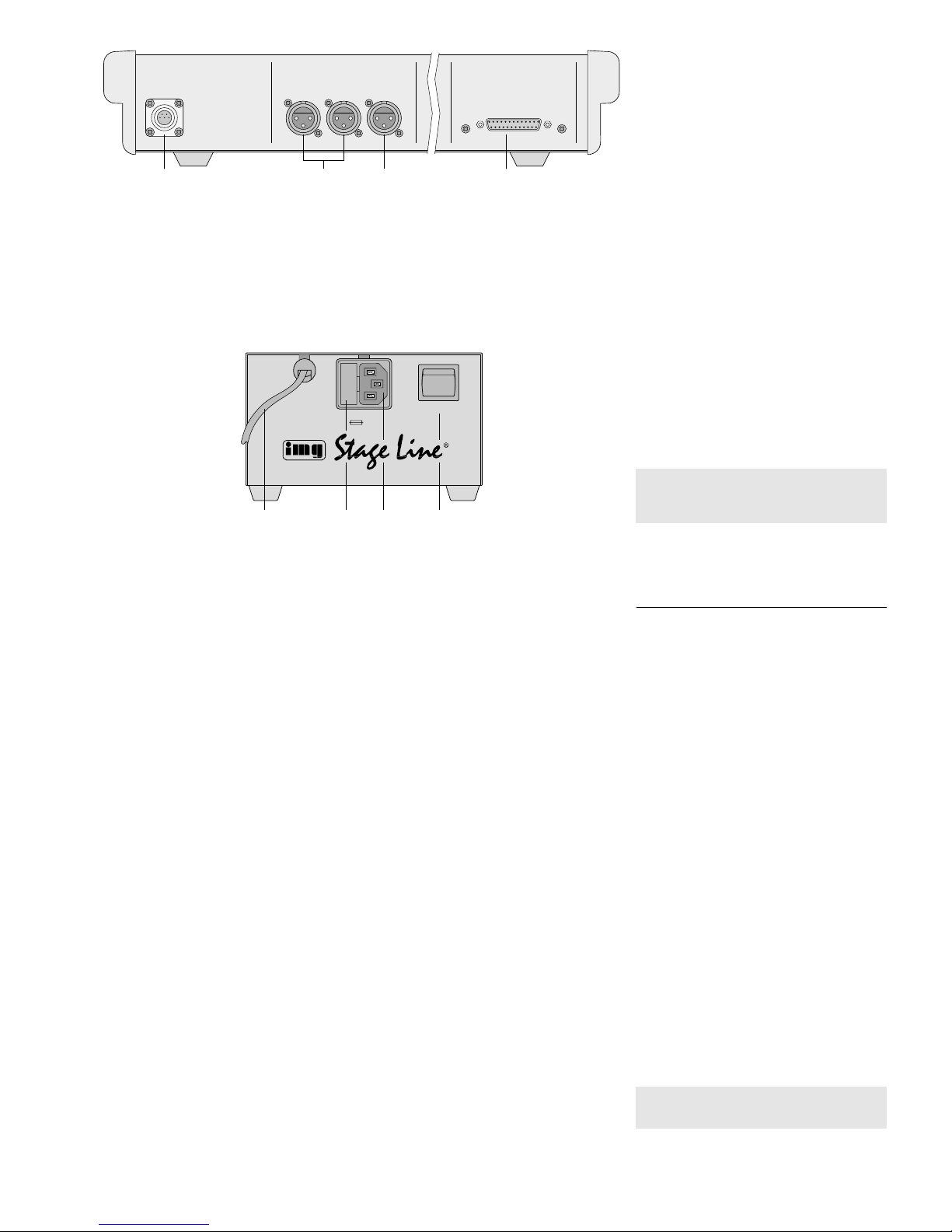
3.4 Rückseite
90 Anschlussbuchse POWER SUPPLY INPUT zur
Stromversorgung über das beiliegende Netzgerät
91 XLR-Buchsen RIGHT und LEFT (sym.) für die
Stereo-Ausgangssumme L-R;
parallel geschaltet mit den Klinkenbuchsen MASTER OUTPUT(79) im Ausgangsfeld, siehe Abb. 4
Hinweis: Werden die Buchsen MASTER OUTPUT asymmetrisch angeschlossen, dann liegt
das Ausgangssignal an den Buchsen RIGHT
und LEFT ebenfalls asymmetrisch an.
92 XLR-Buchse MONO (sym.) für die Mono-Aus-
gangssumme L-R
93 Buchse TR-LINK INPUTzum Anschluss eines Er-
weiterungsmoduls (z.Z. nicht im Liefersortiment)
3.5 Netzgerät
95 Anschlusskabel zur Verbindung mit der Buchse
POWER SUPPLYINPUT (90)
96 Sicherungshalter; eine durchgebrannte Siche-
rung nur durch eine gleichen Typs ersetzen
97 Netzbuchse zum Anschluss an eine Steckdose
(230V~/50Hz) über das beiliegende Netzanschlusskabel
98 Ein-/Ausschalter POWER
4 Modifikationen der Kanalzüge
Bei Bedarf vor dem Anschluss des MMX-206 die folgenden Modifikationen der Kanalzüge durchführen.
1) Falls das Netzgerät angeschlossen und eingeschaltet ist, dieses ausschalten und den Stecker
aus der Steckdose ziehen. Das Netzgerät vom
Mischpult trennen.
Vorsicht! Für diese Änderungen muss das Gerät
geöffnet werden. Darum sollten sie nur
von einer qualifizierten Fachkraft durchgeführt werden.
3.4 Rear side
90 Connection jack POWER SUPPLYINPUTfor the
power supply via the supplied power supply unit
91 XLR jacks RIGHT and LEFT (bal.) for the stereo
master output L-R;
connected in parallel to the 6.3mm jacks
MASTER OUTPUT (79) in the output section,
see fig. 4
Note: If the jacks MASTER OUTPUT are connected unbalanced, then the output signal is also
unbalanced at the jacks RIGHT and LEFT.
92 XLR jack MONO (bal.) for the mono master out-
put L-R
93 Jack TR-LINK INPUT for connection of an exten-
sion module (at present not included in the product range)
3.5 Power supply unit
95 Cable for connection to the jack POWER SUP-
PLYINPUT (90)
96 Fuse holder; only replace a blown fuse by one of
the same type
97 Mains jack for connection to a mains socket
(230V~/50Hz) via the supplied mains cable
98 POWER switch
4 Modifications of the channels includ-
ing control facilities
If necessary, prior to the connection of the MMX206 make the following modifications of the channels including control facilities.
1) If the power supply unit is connected and
switched on, switch it off and disconnect the plug
from the mains socket. Disconnect the power
supply unit from the mixer.
Caution! For these changes the unit must be
opened. Therefore, they should only be
made by qualified, specialized personnel.
POWER SUPPLY
OUTPUT
(FOR USE WITH MMX-206 ONLY)
230V~/50Hz
POWER
ON
OFF
T500mAL
Netzgerät
Power supply unit
95 96 97 98
POWER SUPPLY
INPUT RIGHT LEFT MONO
BALANCED OUTPUTS
TR-LINK INPUT
Anschlüsse auf der Rückseite
Connections at the rear side
90 91 92 93
Fig. 5
Fig. 6
11
2) Die 14 Kreuzschlitzschrauben auf der Mischpultunterseite entfernen und die Bodenplatte abnehmen.
3) Die Modifikationen nach den entsprechenden
Kapiteln 4.1–4.3 durchführen.
4) Die Bodenplatte wieder festschrauben.
4.1 Phantomspeisung für einzelne Mono-
Kanalzüge abschalten
Die 48-V-Phantomspeisung für die Mono-Kanalzüge
ist zentral zuschaltbar. Sie kann jedoch für jeden
dieser Kanäle einzeln abgeschaltet werden, wenn
sowohl asymmetrische als auch phantomgespeiste
Mikrofone angeschlossen werden sollen.
Zum Abschalten der Phantomspeisung auf der
Platine des betreffenden Kanals die Drahtbrücke
LK1 durchtrennen (siehe Abb. 7).
4.2 Phantomspeisung für einzelne Stereo-
Kanalzüge dazuschalten
Wird in einem oder in beiden Stereo-Kanalzügen die
Mikrofon-Phantomspeisung benötigt, die Brücke
LK1 im oberen Bereich der entsprechenden
Leiterplatte einlöten (halb verdeckt durch die Leiterplatte mit den XLR-Ausgangsbuchsen).
4.3 Signalauskoppelpunkte der Auskoppel-
wege A3 bis A6 ändern
1. Für die Wege A3 und A4 wird bei gedrückter
Taste POST/ PRE (14 bzw. 42), siehe Abb. 12,
das Signal pre-fader ausgekoppelt. Durch Umstecken der Brücke JP2 für jeden Kanal getrennt
lässt es sich auch pre-equalizer abnehmen –
siehe Abb. 7.
2. Für die Wege A5 und A6 kann der Signalauskoppelpunkt durch Umstecken der Brücke JP1
für jeden Kanal getrennt von pre-fader auf preequalizer oder post-fader umgestellt werden –
siehe Abb. 7.
LINK
5 Geräte anschließen
Vor dem Anschließen von Geräten bzw. Ändern bestehender Anschlüsse das Mischpult ausschalten.
5.1 Netzgerät
Das Netzgerät an die Buchse POWER SUPPLY
INPUT (90) auf der Mischpultrückseite anschließen.
Das beiliegende Netzkabel zuerst in die Buchse
„230 V~/50 Hz“ (97) des Netzgerätes und dann in
eine Steckdose (230V~/50Hz) stecken.
5.2 Verstärker
1) Den Verstärker für die Saalbeschallung an die
XLR-Buchsen RIGHT und LEFT (91) anschließen
oder bei Mono-Wiedergabe an die Buchse MONO
(92). Alternativ oder zusätzlich für einen weiteren
Verstärker können auch die Klinkenbuchsen
MASTER OUTPUT (75) verwendet werden.
Hinweis: Wird das Buchsenpaar RIGHT und
LEFT oder das Buchsenpaar MASTER OUTPUT
asymmetrisch angeschlossen, dann liegt das
Ausgangssignal auch an dem anderen Buchsenpaar asymmetrisch an.
2) Die Verstärker für die Bühnenbeschallung entsprechend der verwendeten Auskoppelwege an
die Ausgänge A1 bis A6 (77) anschließen oder bei
aktiviertem Stage-Modus an die Ausgänge G1 bis
G4 (60) – siehe auch Kapitel 6.3 „Auskoppelwege
konfigurieren und Stage-Modus aktivieren“.
3) Steht das Mischpult in einem separaten (Regie-)
Raum, den Verstärker für die Monitoranlage an
die Buchse CONTROL ROOM (79) anschließen.
Steckeranschlüsse:
Spitze = linker Kanal
Ring = rechter Kanal
Schaft = Masse
5.3 Kopfhörer
Zur Kontrolle oder zur Einpegelung lassen sich einzelne bzw. mehrere Signale auch über einen Stereo- Kopfhörer (Impedanz ≥ 32Ω) vor den zugehörigen Pegelreglern (PFL) oder nach den Pegelreglern
2) Remove the 14 recessed head screws on the
lower side of the mixer and remove the bottom
plate.
3) Make the modifications according to the corresponding chapters 4.1 to 4.3.
49Fasten the bottom plate with screws.
4.1 Switching off the phantom power for indi-
vidual mono channels
The 48V phantom power for the mono channels can
be centrally switched as a factory setting. However,
it can individually be switched off for each of these
channels for connecting unbalanced microphones
as well as phantom-powered microphones.
To switch off the phantom power on the PCB of
the channel concerned, split the wire jumper LK1
(see fig. 7).
4.2 Switching on the phantom power for indi-
vidual stereo channels
If the phantom power of the microphone is required
in one or in both stereo channels, solder the jumper
LK1 in the upper range of the corresponding
PCB (half concealed by the PCB with XLR output
jacks).
4.3 Changing the signal take-off points of the
AUX send ways A3 to A6
1. For the ways A3 and A4, with the button POST/
PRE (14 or 42) pressed, see fig. 12, the signal is
taken off pre fader. By rearranging the jumper
JP2 separately for each channel it is also possible to take it off pre equalizer – see fig. 7.
2. For the ways A5 and A6 the signal take-off point
can be changed separately for each channel
from pre fader to pre equalizer or post fader by
rearranging the jumper JP1 – see fig. 7.
LINK
5 Connection of the Units
Prior to connecting units or changing existing connections, switch off the mixer.
5.1 Power supply unit
Connect the power supply unit to the jack POWER
SUPPLY INPUT (90) on the rear side of the mixer.
Connect the supplied mains cable to the jack
“230 V~/50 Hz” (97) of the power supply unit first
and then to a mains socket (230V~/50Hz).
5.2 Amplifiers
1) Connect the amplifier for the PA system of the
hall to the XLR jacks RIGHT and LEFT (91) or in
case of mono reproduction to the jack MONO
(92). The 6.3 mm jacks MASTER OUTPUT (75)
can also be used alternatively or additionally for
another amplifier.
Note: If the pair of jacks RIGHT and LEFT or the
pair of jacks MASTER OUTPUT is connected
unbalanced, then the output signal is also unbalanced at the other pair of jacks.
2) Connect the amplifiers for the PAstage system to
the outputs A1 to A6 (77) according to the AUX
send ways used or in case of activated stage
mode to the outputs G1 to G4 (60) – also see
chapter 6.3 “Configuring AUX send ways and
activating the stage mode”.
3) If the mixer is in a separate (control) room,
connect the amplifier for the monitoring system to
the jack CONTROL ROOM (79).
Plug connections:
tip = left channel
ring = right channel
body = ground
5.3 Headphones
For checking or for level adjusting it is possible to
monitor individual or several signals also via stereo
headphones (impedance ≥ 32 Ω) ahead of the corresponding level controls (PFL) or after the level
JP1
LK1
JP2
PRE FADER
PRE EQ
A3+A4
JP1
POST FADER
PRE EQ
PRE FADER
A5+A6
Leiterplatte eines Kanalzugs
PCB of a channel
G1 A1
G2
A2
G3
A3
G4
A4
GROUP/ AUX OUTPUT
LEFT RIGHT
A1
G1 LEFT
A2
G2
RIGHT
A3
G3
MASTER OUTPUT
(TIP: SEND RING: RETURN)
MASTER
INSERT
AUX INPUT 1
LEFT (MONO)
AUX INPUT 2
LEFT (MONO)
RIGHT RIGHT
G1
RIGHT
A4
G4
G2
A5
AUX INPUT 3
LEFT (MONO)
AUX INPUT 4
L
R
GROUP
INSERT
(TIP: SEND RING: RETURN)
A6
CONTROL
ROOM
TAPE REC
L
R
PHANTOM
POWER +48V
+15
12
9
6
3
0dB
75
77
79
60
PHONES
010
LEVEL
CR/ PHONES
PFL SOLO
LISTEN
MODE
PFL/SOLO
G1
1–2
TO L–R
PFL/SOLO
PFL/SOLO
G2
PFL/SOLO
G3
3–4
TO L–R
PFL/SOLO
PFL/SOLO
G4
1–2 3–4
STAGE
MODE
86
Ausschnitte Ausgangsfeld
Details of the output section
Fig. 7
Fig. 8
12
(SOLO) abhören – siehe auch Kap. 6.4 „Abhören
der Kanäle“. Dazu den Kopfhörer an die Buchse
PHONES (86) anschließen.
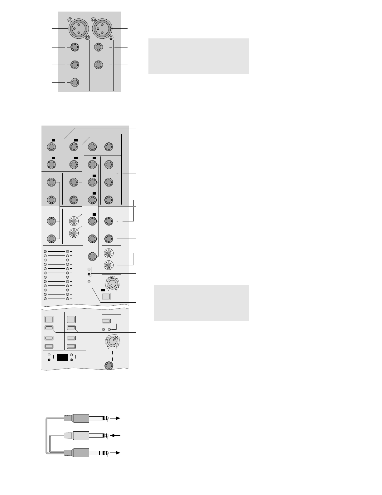
5.4 Mikrofone
1) Benötigen die verwendeten Mikrofone keine Phantomspeisung, den versenken Schalter PHANTOM
POWER +48V (81) nicht drücken. Nach dem Einschalten des Mischpults darf die darüber liegende
gelbe LED nicht leuchten. In diesem Fall können
sowohl symmetrisch als auch asymmetrisch beschaltete Mikrofone angeschlossen werden.
2) Für den Betrieb von phantomgespeisten Mikrofonen den Schalter PHANTOM POWER +48V mit
einem dünnen Gegenstand (z.B. Kugelschreiber)
hineindrücken. Nach dem Einschalten des Mischpults leuchtet die darüber liegende gelbe LED. An
allen XLR-Buchsen MIC (1) der Mono-Eingangskanäle liegt die 48-V-Phantomspeisung an.
In den Mono-Kanälen lässt sich die Phantomspeisung einzeln abschalten (Kap. 4.1) und in den
Stereo-Kanälen einzeln dazuschalten (Kap. 4.2).
3) Die Mikrofone an die XLR-Buchsen MIC (1 und
30) anschließen.
Hinweis: Es kann nicht zwischen den XLR-Buchsen
MIC und den Klinkenbuchsen LINE umgeschaltet
werden. Darum in jedem Kanal entweder die
Buchse MIC oder die Buchse(n) LINE anschließen.
5.5 Instrumente und Geräte mit Line-Ausgang
Signalquellen mit Line-Monoausgang (z.B. Instrumente) an die Buchsen LINE (2) anschließen. Beim
Anschluss von Mono-Geräten an die Stereo-Kanalzüge M1 und M2 jeweils nur die Buchse LEFT (31)
anschließen. Das Eingangssignal wird dann intern auf
Vorsicht!
Die Phantomspeisung nur bei ausgeschaltetem
Mischpult dazu- oder abschalten, sonst entstehen
laute Schaltgeräusche.
An die phantomgespeisten XLR-Buchsen MIC
keine asymmetrischen Mikrofone anschließen.
Diese können beschädigt werden.
den rechten und linken Kanal geschaltet. Stereo-Geräte an die Buchsen LEFT (31) und RIGHT (32) anschließen. Außerdem können die Buchsen AUX INPUT 1 bis 4 (61) im Ausgangsfeld verwendet werden.
Hinweis: In jedem Kanal entweder die XLR-Buchse
MIC oder die Klinkenbuchse(n) LINE anschließen.
5.6 Effektgeräte
A Effektgeräte lassen sich direkt in einen Kanalzug
einschleifen, wobei das zu bearbeitende Signal
komplett über das Effektgerät läuft (z.B. bei
Kompressoren, Noise-Gates, Equalizern) oder
B es werden Signalanteile aus den Eingangs-
kanälen ausgekoppelt, über ein Effektgerät
geführt und nach der Bearbeitung über die Eingänge AUX INPUT 1 bis 4 (61) auf eine Subgruppe G1 bis G4 oder auf die Ausgangssumme
L-R dazugemischt (z.B. bei Hallgeräten).
A Effektgerät einschleifen
Je ein Effektgerät lässt sich in die folgenden Wege
einschleifen:
1. Mono-Kanalzüge: Buchsen INSERT (3)
2. Subgruppen G1 und G2:
Buchsen GROUP INSERT (78)
3. Ausgangssumme L-R:
Buchsen MASTER INSERT (76)
Die benötigten Stecker müssen wie folgt angeschlossen sein:
Spitze = Send (Ausgang)
Ring = Return (Eingang)
Schaft = Masse
Zum Anschluss von Effektgeräten mit getrennten
Ein- und Ausgangsbuchsen werden Y-Kabel benötigt, z.B. MCA-202 aus dem Sortiment von
MONACOR (siehe auch Abb. 11).
B Effektgerät parallel anschließen
1) Die Eingänge des Effektgerätes / der Effektgeräte
an die Ausgänge A1 bis A6 (77) der verwendeten
Auskoppelwege (siehe Kapitel 6.3) anschließen.
2) Die Ausgänge des Effektgerätes/der Effektgeräte an die Eingänge AUX INPUT 1 bis 4 (61) anschließen.
controls (SOLO) – also see chapter 6.4 “Monitoring
the channels”. For this purpose connect the headphones to the jack PHONES (86).
5.4 Microphones
1) If the microphones used do not require any phantom power, do not press the recessed switch
PHANTOM POWER +48 V (81). After switching
on the mixer, the yellow LED above it must not
light up. In this case both balanced and unbalanced microphones can be connected.
2) For the operation of phantom-powered microphones press in the switch PHANTOM POWER
+48V with a thin object (e.g. ball point pen). After
switching on the mixer, the yellow LED above it
lights up. The 48V phantom power is present at
all XLR jacks MIC (1) of the mono input channels.
The phantom power can individually be
switched off in the mono channels (chapter 4.1)
and individually be switched on in the stereo
channels (chapter 4.2).
3) Connect the microphones to the XLR jacks MIC
(1 and 30).
Note: It is not possible to switch between the
XLR jacks MIC and the 6.3mm jacks LINE.
Therefore, connect either the jack MIC or the
jack(s) LINE in each channel.
5.5 Musical instruments and units with line
output
Connect signal sources with mono line output (e. g.
musical instruments) to the jacks LINE (2). When
connecting mono units to the stereo channels M1 and
Attention!
Do not connect any unbalanced microphones to
the phantom-powered XLR jacks MIC. They may
be damaged.
Only switch the phantom power on or off with the
mixer switched off, otherwise loud switching
noise will occur.
M2, only connect the jack LEFT (31) respectively.
Then the input signal is internally switched to the right
and left channels. Connect stereo units to the jacks
LEFT(31) and RIGHT (32). In addition, the jacks AUX
INPUT 1 to 4 (61) in the output section can be used.
Note: Connect either the XLR jack MIC or the
6.3mm jack(s) LINE in each channel.
5.6 Effect units
A Effect units can directly be inserted in a channel,
in which case the signal to be processed is
routed completely via the effect unit (e.g. in case
of compressors, noise-gates, equalizers) or
B signal parts are taken off from the input channels,
guided via an effect unit, and after processing via
the inputs AUX INPUT1 to 4 (61) they are added
to a subgroup G1 to G4 or to the master output
L-R (e.g. in case of reverb units).
A Inserting an effect unit
One effect unit each can be inserted in the following
ways:
1. mono channels: jacks INSERT (3)
2. subgroups G1 and G2:
jacks GROUP INSERT (78)
3. Master output L-R:
jacks MASTER INSERT (76)
The required plugs have to be connected as follows:
tip = Send (output)
ring = Return (input)
body = ground
For the connection of effect units with separate input
jacks and output jacks, Y cables are required, e. g.
MCA-202 of the product range of MONACOR (also
see fig. 11).
B Connecting an effect unit in parallel
1) Connect the inputs of the effect unit(s) to the outputs A1 to A6 (77) of the AUX send ways used
(see chapter 6.3).
2) Connect the outputs of the effect unit(s) to the
inputs AUX INPUT1 to 4 (61).
LINE
MIC
INSERT
DIRECT
OUT
14
(TIP: SEND RING: RETURN)
1
2
3
4
30
31
32
LEFT
(MONO)
MIC
RIGHT
M1
STEREO LINE
Ausschnitt Eingängskanäle 14 und M1
Detail of the input channels 14 and M1
78
60
G1 A1
G2
A2
G3
A3
G4
A4
GROUP/ AUX OUTPUT
LEFT RIGHT
A1
G1 LEFT
A2
G2
RIGHT
A3
G3
MASTER OUTPUT
(TIP: SEND RING: RETURN)
MASTER
INSERT
AUX INPUT 1
LEFT (MONO)
AUX INPUT 2
LEFT (MONO)
RIGHT RIGHT
G1
RIGHT
A4
G4
G2
A5
AUX INPUT 3
LEFT (MONO)
AUX INPUT 4
L
R
GROUP
INSERT
(TIP: SEND RING: RETURN)
A6
CONTROL
ROOM
TAPE REC
L
R
PHANTOM
POWER +48V
POWER
LEFT RIGHT
+15
12
9
6
3
0dB
3
6
9
12
15
-20
010
PFL/SOLO
A1
G1
81
75
76
77
79
80
61
63
PHONES
010
LEVEL
CR/ PHONES
PFL SOLO
LISTEN
MODE
PFL/SOLO
G1
1–2
TO L–R
PFL/SOLO
PFL/SOLO
G2
PFL/SOLO
G3
3–4
TO L–R
PFL/SOLO
PFL/SOLO
G4
1–2 3–4
STAGE
MODE
71
86
Ausschnitte Ausgangsfeld
Details of the output section
Fig. 9
Fig. 10
Y-Kabel MCA-202
Y cable MCA-202
Fig. 11
MMX-206
INSERT
Signal
Signal
RETURN SEND
RETURN
SEND
rot/ red
schwarz/ black
schwarz/ black
13
5.7 Aufnahmegeräte
Ein Mehrspurgerät lässt sich an die Buchsen
DIRECT OUT (4) anschließen. Hier liegt jeweils das
bearbeitete Kanalsignal nach dem Kanal-Fader an.
Für die Aufnahme der Ausgangssumme L-R das
Aufnahmegerät an den Ausgang TAPE REC (80)
anschließen. Der Aufnahmepegel ist abhängig von
der Stellung des Faders R-L (87)*.
6 Bedienung
Vor dem Einschalten sollten die Fader der Subgruppen G1 bis G4 (74)*, der Fader für die Ausgangssumme L-R (87)*, der Pegelregler für die Monitoranlage (85)* und alle Pegelregler der Auskoppelwege
A1 bis A6 (82)* auf Minimum gestellt werden, um Einschaltgeräusche zu vermeiden. Dann das Mischpult
mit dem Schalter POWER am Netzgerät einschalten.
Die Betriebsanzeige POWER (63) leuchtet. Anschließend die angeschlossenen Geräte einschalten.
Nach dem Betrieb das Mischpult wieder mit dem
Schalter POWER ausschalten.
6.1 Grundeinstellung der Eingangskanäle
6.1.1 Vorbereitung
1) Zunächst die folgenden Regler in die Mittelstel-
lung drehen
in den Mono-Kanalzügen:
die Regler GAIN (5) für die Vorverstärkung,
die Klangregler HI (7), MID (8, 9) und LO (10),
die Panoramaregler PAN (16);
*siehe Abb. 4, 14, 16
Vorsicht! Stellen Sie die Lautstärke der Audio-
anlage und die Kopfhörerlautstärke nie
sehr hoch ein. Hohe Lautstärken können auf Dauer das Gehör schädigen!
Das menschliche Ohr gewöhnt sich an
große Lautstärken und empfindet sie
nach einiger Zeit als nicht mehr so
hoch. Darum eine hohe Lautstärke nach
der Gewöhnung nicht weiter erhöhen.
in den Stereo-Kanalzügen:
die Regler GAIN MIC (33) und GAIN LINE (34)
für die Vorverstärkung,
die Klangregler HI (36), MID (37) und LO (38),
die Balanceregler BAL (44).
2) In allen Kanalzügen die Pegelregler für die Auskoppelwege A1 bis A6 (11, 13, 15, 39, 41, 43) auf
Null drehen.
3) Die Tasten MUTE (17, 45) und PFL/ SOLO (23,
51) dürfen nicht gedrückt sein.
4) Vorerst die Kanalfader (24, 52) ganz zuziehen.
6.1.2 Kanalzüge auf die Subgruppen oder
auf die Ausgangssumme L-R schalten
1) Mit den Routing-Tasten die Ausgangssumme und/
oder die Subgruppen, auf die der jeweilige Kanal
geschaltet werden soll, anwählen:
Taste L-R (18, 46) für die Ausgangssumme L-R
Taste 1-2 (19, 47) für die Subgruppe 1-2
Taste 3-4 (20, 48) für die Subgruppe 3-4
2) Soll ein Subgruppenpaar auf die Ausgangssumme L-R geschaltet werden, die Taste 1-2 TO L-R
(71) für das Subgruppenpaar G1, G2 drücken
und/oder die Taste 3-4 TO L-R (71) für das Subgruppenpaar G3, G4.
Hinweis: Bei aktiviertem Stage-Modus (siehe
Kapitel 6.3) werden mit diesen Tasten nicht die
Subgruppen auf die Ausgangssumme geschaltet, sondern die Auskoppelwege A1 und A2 sowie
A3 und A4!
6.1.3 Eingangskanäle aussteuern und
Klang einstellen
1) Jeweils ein Tonsignal (Testsignal oder Musikstück) auf die Kanäle geben. Die zugehörigen
LEDs SIGNAL (22, 50) leuchten bei einer Eingangssignalstärke größer als
-
20dB.
2) Damit ein Signal über die angeschlossene Audioanlage gehört werden kann, zunächst am ersten
verwendeten Kanalzug den Kanalfader (24, 52)
auf ca. 0dB schieben. Falls das Signal über eine
5.7 Recording units
Connect a multi-track unit to the jacks DIRECT OUT
(4). The processed channel signal is present after
the channel fader in each case.
For the recording of the master output L-R
connect the recording unit to the output TAPE REC
(80). The recording level depends on the position of
the fader R-L (87)*.
6 Operation
Prior to switching-on, the faders of the subgroups G1
to G4 (74)*, the fader for the master output L-R (87)*,
the level control for the monitoring system (85)*, and
all level controls of the AUX send ways A1 to A6 (82)*
should be set to minimum to avoid loud switching-on
noise. Then switch on the mixer with the POWER
switch at the power supply unit. The POWER LED
(63) lights up. Then switch on the connected units.
After the operation switch off the mixer with the
POWER switch.
6.1 Basic setting of the input channels
6.1.1 Preparation
1) First turn the following controls to mid-position
for the mono channels:
the controls GAIN (5) for the preamplification,
the equalizer controls HI (7), MID (8, 9), and
LO (10),
the panorama controls PAN (16);
*see figs. 4, 14, 16
Caution! Do not adjust the volume of the audio
system and the headphone volume very
high. Permanent high volumes may
damage your hearing! The human ear
gets accustomed to high volumes which
do not seem to be that high any more
after some time. Therefore, do not further
increase a high volume which has once
been adjusted after getting used to it.
for the stereo channels:
the controls GAIN MIC (33) and GAIN LINE (34)
for the preamplification,
the equalizer controls HI (36), MID (37), and
LO (38), the balance controls BAL (44).
2) For all channels turn the level controls for the
AUX send ways A1 to A6 (11, 13, 15, 39, 41, 43)
to zero.
3) The buttons MUTE (17, 45) and PFL/SOLO (23,
51) must not be pressed.
4) For the time being, completely close the channel
faders (24, 52).
6.1.2 Switching the channels to the subgroups
or to the master output L-R
1) With the routing buttons select the master output
and/ or the subgroups to which the respective
channel is to be switched:
button L-R (18, 46) for the master output L-R
button 1-2 (19, 47) for the subgroup 1-2
button 3-4 (20, 48) for the subgroup 3-4
2) For switching a pair of subgroups to the master
output L-R, press the button 1-2 TO L-R (71) for
the pair of subgroups G1, G2 and/or the button
3-4 TO L-R (71) for the pair of subgroups G3, G4.
Note: With activated stage mode (see chapter
6.3), with these buttons the subgroups are not
switched to the master output but the AUX send
ways A1 and A2 as well as A3 and A4!
6.1.3 Adjusting the level control of the input
channels and the sound
1) Feed one audio signal each (test signal or music
piece) to the channels. The corresponding LEDs
SIGNAL (22, 50) light up with an input signal
value above
-
20dB.
2) For hearing a signal via the connected audio
system, first move the channel fader (24, 52) of
the first channel used to approx. 0dB. If the
signal is guided via one of the subgroups G1 to
G4, move the corresponding faders (74) to
LR
010
010
010
010
010
010
–+
–+
350
–+
450
1k
1k8
2k5
5k
6kHz
12 60dB
100Hz
40
15
20
PFL/SOLO
1
SIGNAL
PEAK
3–4
1–2
L–R
MUTE
14
PAN
A6
A5
A4
A3
A2
A1
LO
MID
HI
14
LINE
MIC
INSERT
DIRECT
OUT
14
(TIP: SEND RING: RETURN)
30
GAIN
POST
PRE
POST
PRE
∞
–10
–5
0dB
+5
+10
1
2
3
4
5
6
7
8
9
10
11
12
14
16
17
18
19
20
21
22
23
24
SIGNAL
PEAK
3–4
1–2
L–R
MUTE
M1
BAL
30
31
32
33
35
36
37
38
41
44
45
46
47
48
49
50
51
LEFT
(MONO)
MIC
RIGHT
M1
STEREO LINE
LR
010
010
010
010
010
010
PFL/SOLO
M1
M1
–+
LO
–+
MID
–+
HI
A6
A5
A4
A3
A2
A1
12 60dB
40
15
20
30
0 +20dB
+5
+15
+10
MIC
LINE
EQ ASSIGN
POST
PRE
POST
PRE
MIC
LINE
∞
–10
–5
0dB
+5
+10
34
40
42
52
GAIN
13
15
43
39
Eingangskanäle 14 und M1
Input channels 14 and M1
Fig. 12
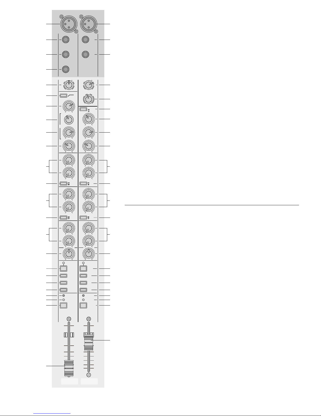
14
der Subgruppen G1 bis G4 geführt wird, die zugehörigen Fader (74) ebenfalls auf ca. 0dB stellen. Den Fader L-R (87) für die Ausgangssumme
L-R so weit aufziehen, dass das Signal zu hören
ist. Das Signal lässt sich auch über einen Kopfhörer oder eine Monitoranlage kontrollieren –
siehe dazu Kapitel 6.4 „Abhören der Kanäle“.
3) Im Ausgangsfeld darf die Taste LISTEN MODE
(84) nicht gedrückt sein. Die grüne LED PFL
unterhalb der Taste leuchtet. Leuchtet die gelbe
LED SOLO, die Taste LISTEN MODE ausrasten.
Blinkt die grüne LED PFL, ist mindestens eine
Taste PFL /SOLO (23, 51) gedrückt. Alle Tasten
PFL/ SOLO, auch die im Ausgangsfeld (68, 70,
72, 83), ausrasten.
4) Die Taste PFL/ SOLO (23, 51) des einzustellenden Kanals drücken. Die grüne LED unterhalb
der Taste LISTEN MODE blinkt. Die Aussteuerungsanzeige (62) zeigt den Pegel vor dem
Fader des gewählten Kanalzugs an.
5) Mit dem zugehörigen Regler GAIN (5) oder im Stereo-Kanalzug mit dem Regler GAIN MIC (33) bzw.
GAIN LINE (34) anhand der Aussteuerungsanzeige den Eingang optimal einpegeln: Bei lauten
Passagen sollte die grüne LED „0dB“ aufleuchten.
Falls erforderlich, kann der Regler auch ganz nach
links oder rechts gedreht werden. Bei Übersteuerung leuchtet permanent die rote LED PEAK (21,
49) im Kanalzug auf. Dann den Regler entsprechend zurückdrehen. Leuchtet die LED nur kurz
auf, wird der Kanal noch nicht übersteuert.
6) In den Stereo-Kanalzügen mit den Zuordnungsschaltern EQ ASSIGN (35) jeweils die Klangregelung für die angeschlossene Eingangsbuchse
[MIC (30) oder LINE (31, 32)] anwählen.
7) Den Klang mit den Reglern HI (7, 36) für die
Höhen, MID (9, 37) für die Mitten und LO (10, 38)
für die Bässe einstellen (±15 dB). In den MonoKanalzügen mit dem oberen Regler MID (8) die
Mittenfrequenz zwischen 350 Hz und 6 kHz einstellen sowie bei Bedarf das 100-Hz-Filter (Hochpass) mit der T aste (6) einschalten. Dadurch wer-
den unerwünschte Signalanteile unter 100Hz,
z. B. Brummen und Trittschall, unterdrückt. Anschließend die Aussteuerung des Kanals überprüfen und ggf. korrigieren.
8) Das Mono-Kanalsignal mit dem Regler PAN (16)
in der Stereo-Basis platzieren oder im StereoKanalzug mit dem Regler BAL (44) die Balance
einstellen.
9) Die Taste MUTE (17, 45) drücken, damit bei den
Einstellungen für den nächsten Kanal das Signal
des ersten Kanals nicht stört. Die Pegel-, Klangund Panorama- bzw. Balanceeinstellung für alle
weiteren Kanalzüge wiederholen.
6.2 Eingangssignale mischen
1) Bei den Kanalzügen, deren Signale auf die Ausgangssumme L-R oder auf eine Subgruppe gemischt werden sollen, die Taste MUTE (17, 45)
wieder ausrasten. Die LED über der T aste erlischt.
2) Mit den Fadern (24, 52) der Eingangskanäle das
gewünschte Lautstärkeverhältnis der Tonquellen
untereinander einstellen: Die Tonquellen, die am
lautesten zu hören sein sollen, optimal aussteuern (siehe Kap. 6.1.3) und die Pegel der übrigen
Tonquellen entsprechend reduzieren.
Wird ein Kanal nicht benutzt, sollte sein Fader
auf Minimum gestellt oder die Taste MUTE
gedrückt werden.
3) Zum Einstellen des Pegels der Ausgangssumme
L-R die Aussteuerungsanzeige (62) auf dieses
Signal schalten: Alle Tasten PFL/ SOLO (23, 51),
auch die im Ausgangsfeld (68, 70, 72, 83), ausrasten. Die grüne LED PFL oder die gelbe LED
SOLO darf nicht blinken.
4) Mit dem Fader L-R (87) den Pegel der Ausgangssumme einstellen. In der Regel wird eine optimale
Aussteuerung erreicht, wenn die Aussteuerungsanzeige bei durchschnittlich lauten Passagen
Werte im 0-dB-Bereich anzeigt (Anzeige 0 dB =
1,23V). Ist der Ausgangspegel jedoch für das
nachfolgende Gerät zu hoch oder zu niedrig,
approx. 0dB as well. Advance the fader L-R (87)
for the master output L-R to such an extent that
the signal can be heard. The signal can also be
checked via headphones or a monitoring system
– see chapter 6.4 “Monitoring the channels”.
3) In the output section the button LISTEN MODE
(84) must not be pressed. The green LED PFL
below the button lights up. If the yellow LED
SOLO lights up, disengage the button LISTEN
MODE.
If the green LED PFLflashes, at least one button PFL/SOLO (23, 51) is pressed. Disengage all
buttons PFL/SOLO, also those in the output section (68, 70, 72, 83).
4) Press the button PFL/SOLO (23, 51) of the channel to be adjusted. The green LED below the button LISTEN MODE flashes. The level display (62)
shows the level ahead of the fader of the selected
channel.
5) Obtain an optimum input level by means of the
level display with the corresponding control GAIN
(5) or for the stereo channel with the control
GAIN MIC (33) or GAIN LINE (34): the green
LED “0 dB” should light up with music peaks. If
required, the control can completely be turned to
the left or right. In case of overload the red LED
PEAK (21, 49) of the channel lights up continuously. Then turn back the control correspondingly. If the LED only lights up shortly, the channel
is not yet overloaded.
6) For the stereo channels select the corresponding
equalizer for the connected input jack [MIC (30)
or LINE (31, 32)] with the assign switches EQ
ASSIGN (35).
7) Adjust the sound with the controls HI (7, 36) for
the high range, MID (9, 37) for the midrange, and
LO (10, 38) for the bass range (±15dB). For the
mono channels, adjust the mid-frequency between 350 Hz and 6 kHz with the upper control
MID (8) and, if required, switch on the 100Hz filter (high pass) with the button (6). Thus, unwanted signal parts below 100Hz, e.g. hum and rum-
ble, are suppressed. Then check the level of the
channel and correct it, if necessary.
8) Place the mono channel signal with the control
PAN (16) in the stereo basis or adjust the balance
with the control BAL (44) in the stereo channel.
9) Press the button MUTE (17, 45) so that the signal
of the first channel does not interfere when
adjustments for the next channel are made.
Repeat the adjustments of level, sound, and panorama or balance for all further channels.
6.2 Adding the input signals
1) Disengage the button MUTE (17, 45) of the channels, the signals of which are to be added to the
master output L-R or to a subgroup. The LED
above the button extinguishes.
2) Adjust the desired volume ratio of the audio sources with each other by means of the faders (24,
52) of the input channels: obtain an optimum
level for the audio sources to be heard at highest
volume (see chapter 6.1.3) and reduce the levels
of the remaining audio sources accordingly.
If a channel is not used, its fader should be
set to minimum or the button MUTE should be
pressed.
3) For adjusting the level of the master output L-R,
switch the level display (62) to this signal: disengage all buttons PFL/SOLO (23, 51), also those
in the output section (68, 70, 72, 83). The green
LED PFLor the yellow LED SOLO must not flash.
4) Adjust the level of the master output with the
fader L-R (87). Generally an optimum level is
obtained if the level display shows values in the
0 dB range at average volume of music pieces
(display 0dB =1.23 V). However, if the output
level is too high or too low for the following unit,
the level of the master output has to be adjusted
lower or higher accordingly.
5) For the additional inputs AUX INPUT 1 and 2 select with the routing buttons (67) the master output or the pair of subgroups to which the respec-
LR
010
010
010
010
010
010
–+
–+
350
–+
450
1k
1k8
2k5
5k
6kHz
12 60dB
100Hz
40
15
20
PFL/SOLO
1
SIGNAL
PEAK
3–4
1–2
L–R
MUTE
14
PAN
A6
A5
A4
A3
A2
A1
LO
MID
HI
14
LINE
MIC
INSERT
DIRECT
OUT
14
(TIP: SEND RING: RETURN)
30
GAIN
POST
PRE
POST
PRE
∞
–10
–5
0dB
+5
+10
1
2
3
4
5
6
7
8
9
10
11
12
14
16
17
18
19
20
21
22
23
24
SIGNAL
PEAK
3–4
1–2
L–R
MUTE
M1
BAL
30
31
32
33
35
36
37
38
41
44
45
46
47
48
49
50
51
LEFT
(MONO)
MIC
RIGHT
M1
STEREO LINE
LR
010
010
010
010
010
010
PFL/SOLO
M1
M1
–+
LO
–+
MID
–+
HI
A6
A5
A4
A3
A2
A1
12 60dB
40
15
20
30
0 +20dB
+5
+15
+10
MIC
LINE
EQ ASSIGN
POST
PRE
POST
PRE
MIC
LINE
∞
–10
–5
0dB
+5
+10
34
40
42
52
GAIN
13
15
43
39
Eingangskanäle 14 und M1
Input channels 14 and M1
Fig. 13
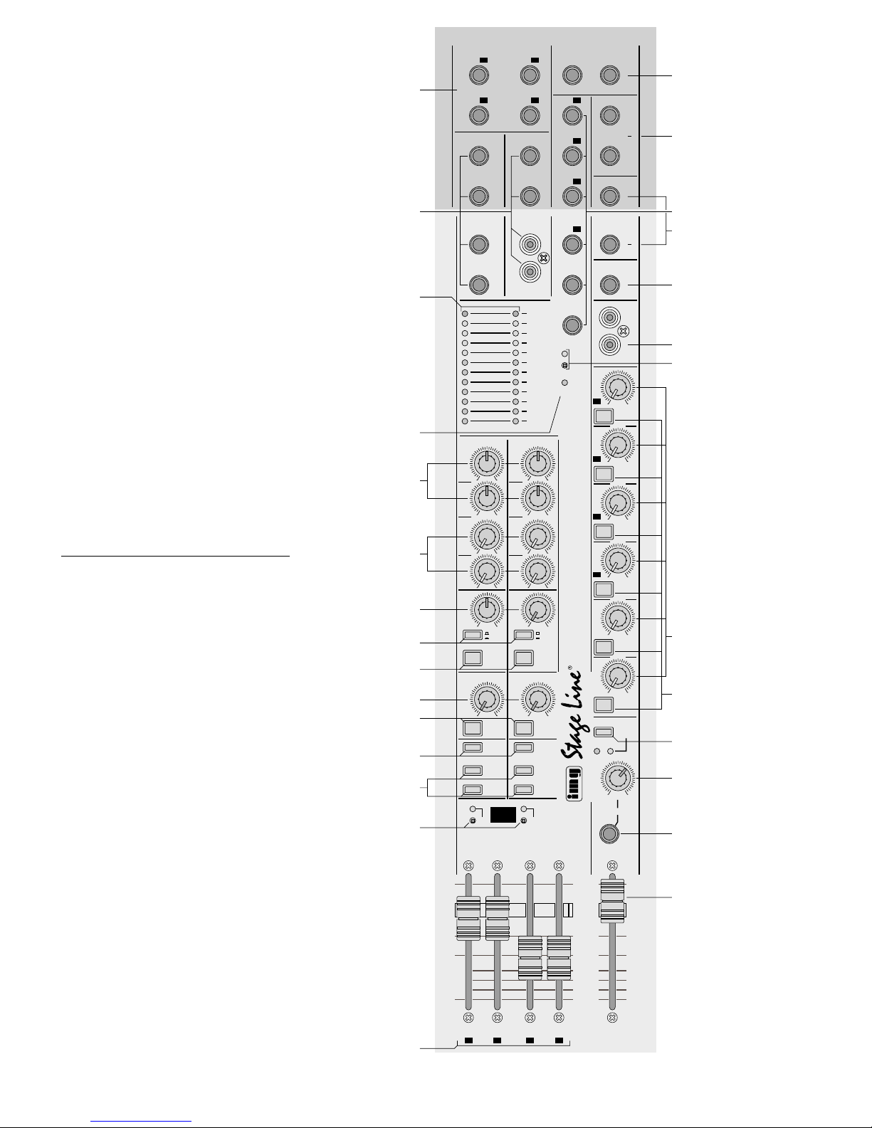
15
muss der Pegel der Ausgangssumme entsprechend niedriger oder höher eingestellt werden.
5) Für die Zusatzeingänge AUX INPUT 1 und 2 mit
den Routing-Tasten (67) die Ausgangssumme
oder das Subgruppenpaar anwählen, auf welches das jeweilige Signal geschaltet werden soll:
Taste nicht gedrückt – Ausgangssumme L-R
Taste gedrückt – AUX 1 auf Gruppe G1 und G2
AUX 2 auf Gruppe G3 und G4
Mit den Reglern LEVEL (66) die Signale auf den
angewählten Weg mischen und mit den Reglern
HI und LO (64) den Klang einstellen.
6) Die Signale der Zusatzeingänge AUX INPUT 3
und 4 mit den Reglern (69) auf die Ausgangssumme L-R mischen.
7) Die Regler der nicht benutzten Zusatzeingänge
auf Null drehen.
8) Werden Kanäle auf eine der Subgruppen gemischt (z.B. alle Mikrofone eines Schlagzeuges),
zuerst die Pegel dieser Kanäle untereinander mit
den Kanalfadern optimal abstimmen und dann die
Lautstärke der Subgruppe mit dem entsprechenden Fader G1 bis G4 (74). Werden die Subgruppen auf die Ausgangssumme geschaltet, liegen
die Gruppen G1 und G3 auf dem linken Kanal und
die Gruppen G2 und G4 auf dem rechten Kanal.
6.3 Auskoppelwege konfigurieren und
Stage-Modus aktivieren
1) Zuerst überlegen, ob es günstiger ist, im NormalModus die Summensignale der Auskoppelwege
A1 bis A4 über die Regler A1 bis A4 (82) zu regeln
oder diese Summensignale im Stage-Modus über
die Fader G1 bis G4 (74).
Soll der Stage-Modus aktiviert werden, kann
das getrennt für die Auskoppelwege A1, A2 und
die Wege A3, A4 erfolgen. Dazu mit einem dünnen
Gegenstand (z. B. kleiner Schraubendreher oder
Kugelschreiber) die versenkte Taste 1-2 und/oder
3-4 (73) drücken. Bei gedrückter Taste leuchtet
die darüber liegende grüne Kontroll-LED und:
tive signal is to be switched:
button not pressed – master output L-R
button pressed – AUX 1 to group G1 and G2
AUX 2 to group G3 and G4
Add the signals to the selected way with the controls LEVEL (66) and adjust the sound with the
controls HI and LO (64).
6) Add the signals of the additional inputs AUX
INPUT 3 and 4 with the controls (69) to the
master output L-R.
7) Turn the controls of the additional inputs not used
to zero.
8) If channels are added to one of the subgroups
(e.g. all microphones of the drums), first tune the
levels of these channels with each other in an
optimum way by means of the channel faders
and then tune the volume of the subgroup with
the corresponding fader G1 to G4 (74). If the subgroups are switched to the master output, the
groups G1 and G3 are on the left channel, and
the groups G2 and G4 are on the right channel.
6.3 Configuring the AUX send ways and
activating the stage mode
1) First consider which way is more advantageous:
in the normal mode to adjust the master signals
of the AUX send ways A1 to A4 via the controls
A1 to A4 (82) or in the stage modeto adjust these
master signals via the faders G1 to G4 (74).
Activating the stage mode can separately be
made for the AUX send ways A1, A2 and the
ways A3, A4. Press the recessed button 1-2 and/
or 3-4 (73) with a thin object (e. g. small screwdriver or ball point pen). With the button pressed,
the green indicating LED above it lights up and:
1. The faders for the subgroups G1 and G2 (74)
are exchanged with the level controls (82) for
the AUX send ways A1 and A2.
2. The corresponding output jacks G1 and G2
(60) are exchanged with the output jacks A1
and A2 (77).
60
G1 A1
G2
A2
G3
A3
G4
A4
GROUP/ AUX OUTPUT
LEFT RIGHT
A1
G1 LEFT
A2
G2
RIGHT
A3
G3
MASTER OUTPUT
(TIP: SEND RING: RETURN)
MASTER
INSERT
AUX INPUT 1
LEFT (MONO)
AUX INPUT 2
LEFT (MONO)
RIGHT RIGHT
G1
RIGHT
A4
G4
G2
A5
AUX INPUT 3
LEFT (MONO)
AUX INPUT 4
L
R
GROUP
INSERT
(TIP: SEND RING: RETURN)
A6
CONTROL
ROOM
TAPE REC
L
R
PHANTOM
POWER +48V
POWER
LEFT RIGHT
+15
12
9
6
3
0dB
3
6
9
12
15
-20
010
PFL/SOLO
A1
G1
010
PFL/SOLO
A2
G2
010
PFL/SOLO
A3
G3
010
PFL/SOLO
A4
010
PFL/SOLO
A5
010
PFL/SOLO
A6
∞
–10
–5
0dB
+5
+10
∞
–10
–5
0dB
+5
+10
G1 G2 G3 G4
A1 A2 A3 A4
L – R
PHONES
010
LEVEL
CR/ PHONES
PFL SOLO
LISTEN
MODE
PFL/SOLO
G1
1–2
TO L–R
PFL/SOLO
PFL/SOLO
G2
010
PFL/SOLO
L–R
1–2
010
010
–+
010
–+
AUX INPUT 1
LO
HI
A5
A6
LEVEL
AUX INPUT 3
PFL/SOLO
G3
3–4
TO L–R
PFL/SOLO
PFL/SOLO
G4
010
PFL/SOLO
L–R
3–4
010
010
–+
010
–+
AUX INPUT 2
LO
HI
A5
A6
LEVEL
AUX INPUT 4
1–2 3–4
STAGE
MODE
MMX-206
16 CHANNEL PRO AUDIO MIXER
ULTRA LOW NOISE DESIGN
G4
75
76
61 77
79
78
62
80
82
83
81
63
64
65
66
68
67
69
70
71
72
73
74
84
85
86
87
Ausgangsfeld
Output section
Fig. 14
 Loading...