

IMG STAGE LINE MMX-142, MMX-182 Instruction Manual
BEDIENUNGSANLEITUNG • INSTRUCTION MANUAL
MODE D’EMPLOI • ISTRUZIONI PER L’USO • GEBRUIKSAANWIJZING • CONSEJOS DE SEGURIDAD
SIKKERHEDSOPLYSNINGER • SÄKERHETSFÖRESKRIFTER • TURVALLISUUDESTA
14-KANAL- UND 18-KANALAUDIOMISCHPULT
14-Channel and 18-Channel Audio Mixer
Table de mixage audio 14 canaux et 16 canaux
Mixer audio a 14 e a 18 canali
MMX-142 Best.-Nr. 20.1900
MMX-182 Best.-Nr. 20.1910

2
wwwwww..iimmggssttaaggeelliinnee..ccoomm
Bevor Sie einschalten ...
Wir wünschen Ihnen viel Spaß mit Ihrem neuen Gerät
von „img Stage Line“. Dabei soll Ihnen diese Bedienungsanleitung helfen, alle Funktionsmöglichkeiten kennen zu lernen. Die Beachtung der Anleitung vermeidet
außerdem Fehlbedienungen und schützt Sie und Ihr
Gerät vor eventuellen Schäden durch unsachgemäßen
Gebrauch.
Den deutschen Text finden Sie auf den Seiten 4– 10.
Before you switch on ...
We wish you much pleasure with your new unit by “img
Stage Line”. With these operating instructions you will be
able to get to know all functions of the unit. By following
these instructions false operations will be avoided, and
possible damage to you and your unit due to improper
use will be prevented.
You will find the English text on the pages 4–10.
D
A
CH
GB
Avant toute mise en service ...
Nous vous remercions d’avoir choisi un appareil “img
Stage Line” et vous souhaitons beaucoup de plaisir à
l’utiliser. Cette notice a pour objectif de vous aider à
mieux connaître les multiples facettes de l’appareil et à
vous éviter toute mauvaise manipulation.
La version française se trouve pages 11–17.
Prima di accendere ...
Vi auguriamo buon divertimento con il Vostro nuovo apparecchio “img Stage Line”. Le istruzioni per l’uso Vi possono
aiutare a conoscere tutte le possibili funzioni. E
rispettando quanto spiegato nelle istruzioni, evitate di
commettere degli errori, e così proteggete Voi stessi, ma
anche l’apparecchio, da eventuali rischi per uso improprio.
Il testo italiano lo potete trovare alle pagine 11–17.
F
B
CH
I
Voordat u inschakelt ...
Wij wensen u veel plezier met uw nieuw toestel van “img
Stage Line”. Met behulp van bijgaande gebruiksaanwijzing zal u alle functiemogelijkheden leren kennen.
Door deze instructies op te volgen zal een slechte werking vermeden worden, en zal een eventueel letsel aan
uzelf en schade aan uw toestel tengevolge van onzorgvuldig gebruik worden voorkomen.
U vindt de nederlandstalige tekst op de pagina’s 18– 21.
Antes de cualquier instalación ...
Tenemos de agradecerle el haber adquirido un equipo
de “img Stage Line” y le deseamos un agrable uso. Por
favor lee las instrucciones de seguridad antes del uso.
La observación de las instrucciones de seguridad evita
operaciones erróneas y protege Vd. y vuestro aparato
contra todo daño posible por cualquier uso inadecuado.
Las instrucciones de seguridad se encuentran en la
página 22.
NL
B
E
Inden De tænder for apparatet ...
Vi ønsker Dem god fornøjelse med Deres nye “img Stage
Line” apparat. Læs oplysningerne for en sikker brug af apparatet før ibrugtagning. Følg sikkerhedsoplysningerne for
at undgå forkert betjening og for at beskytte Dem og
Deres apparat mod skade på grund af forkert brug.
Sikkerhedsoplysningerne finder De på side 22.
Förskrift
Vi önskar dig mycket nöje med din nya enhet från “img
Stage Line”. Läs gärna säkerhetsinstruktionerna innan
du använder enheten. Genom att följa säkerhetsinstruktionerna kan många problem undvikas, vilket annars kan
skada enheten.
Du finner säkerhetsinstruktionerna på sidan 22.
DK
S
Ennen virran kytkemistä...
Toivomme, että uusi “img Stage Line”-laitteesi tuo sinulle
paljon iloa ja hyötyä. Ole hyvä ja lue käyttöohjeet ennen
laitteen käyttöönottoa. Luettuasi käyttöohjeet voit käyttää laitetta turvallisesti ja vältyt laitteen väärinkäytöltä.
Käyttöohjeet löydät sivulta 23.
FIN
3
➃
1 2345678910
TAPE PLAY
LR
TAPE REC
11/12 13/14
∞
0dB
+5
– 5
– 10
– 20
– 30
∞
0dB
+5
– 5
– 10
– 20
– 30
LR
PHONES
LEVEL
AUX1 SEND
AUX2 SEND
AUXINPUT
PHANTOM
POWER +48V
POWER
LEFT RIGHT
+15
12
9
6
3
0dB
3
6
9
12
15
-20
LR
POWER
AUX
SEND
AUX
INPUT
LEFT
(MONO)
RIGHT
1
2
SEND/
RETURN
OUTPUT
BAL.
LEFT RIGHT
LEFT
(MONO)
RIGHT
LEFT
(MONO)
RIGHT
11/12 13/14
∞
0dB
+5
+10
– 5
– 10
– 20
– 30
MMX-142
14 CHANNEL PRO AUDIO MIXER ULTRA LOW NOISE DESIGN
9101 2345678
∞
0dB
+5
+10
– 5
– 10
– 20
– 30
PFL
PK
HI
12kHz
LO
45Hz
LEVEL
+4dB
–10dB
+–
+–
BAL
RL
C
100
AUX2
AUX1
100
PFL
PK
HI
12kHz
LO
45Hz
LEVEL
+4dB
–10dB
+–
+–
BAL
RL
C
100
AUX2
AUX1
100
100 100
100
100
LINE
MIC
LINE
MIC
LINE
MIC
LINE
MIC
LINE
MIC
LINE
MIC
LINE
MIC
LINE
MIC
LINE
MIC
LINE
MIC
PFL
PK
∞
0dB
+5
+10
– 5
– 10
– 20
– 30
PAN
RL
C
100
AUX2
AUX1
LO
60Hz
MID
GAIN
HI
12kHz
10 60dB
40
30
350
450
1k
1k8
2k5
5k
6kHz
20
100
+–
+–
+–
PFL
PK
∞
0dB
+5
+10
– 5
– 10
– 20
– 30
PAN
RL
C
100
AUX2
AUX1
LO
60Hz
MID
GAIN
HI
12kHz
10 60dB
40
30
350
450
1k
1k8
2k5
5k
6kHz
20
100
+–
+–
+–
PFL
PK
∞
0dB
+5
+10
– 5
– 10
– 20
– 30
PAN
RL
C
100
AUX2
AUX1
LO
60Hz
MID
GAIN
HI
12kHz
10 60dB
40
30
350
450
1k
1k8
2k5
5k
6kHz
20
100
+–
+–
+–
PFL
PK
∞
0dB
+5
+10
– 5
– 10
– 20
– 30
PAN
RL
C
100
AUX2
AUX1
LO
60Hz
MID
GAIN
HI
12kHz
10 60dB
40
30
350
450
1k
1k8
2k5
5k
6kHz
20
100
+–
+–
+–
PFL
PK
∞
0dB
+5
+10
– 5
– 10
– 20
– 30
PAN
RL
C
100
AUX2
AUX1
LO
60Hz
MID
GAIN
HI
12kHz
10 60dB
40
30
350
450
1k
1k8
2k5
5k
6kHz
20
100
+–
+–
+–
PFL
PK
∞
0dB
+5
+10
– 5
– 10
– 20
– 30
PAN
RL
C
100
AUX2
AUX1
LO
60Hz
MID
GAIN
HI
12kHz
10 60dB
40
30
350
450
1k
1k8
2k5
5k
6kHz
20
100
+–
+–
+–
PFL
PK
∞
0dB
+5
+10
– 5
– 10
– 20
– 30
PAN
RL
C
100
AUX2
AUX1
LO
60Hz
MID
GAIN
HI
12kHz
10 60dB
40
30
350
450
1k
1k8
2k5
5k
6kHz
20
100
+–
+–
+–
PFL
PK
∞
0dB
+5
+10
– 5
– 10
– 20
– 30
PAN
RL
C
100
AUX2
AUX1
LO
60Hz
MID
GAIN
HI
12kHz
10 60dB
40
30
350
450
1k
1k8
2k5
5k
6kHz
20
100
+–
+–
+–
PFL
PK
∞
0dB
+5
+10
– 5
– 10
– 20
– 30
PAN
RL
C
100
AUX2
AUX1
LO
60Hz
MID
GAIN
HI
12kHz
10 60dB
40
30
350
450
1k
1k8
2k5
5k
6kHz
20
100
+–
+–
+–
PFL
PK
∞
0dB
+5
+10
– 5
– 10
– 20
– 30
PAN
RL
C
100
AUX2
AUX1
LO
60Hz
MID
GAIN
HI
12kHz
10 60dB
40
30
350
450
1k
1k8
2k5
5k
6kHz
20
100
+–
+–
+–
1
11/12
LEFT
(MONO)
RIGHT
11/12
1
∞
0dB
+5
+10
– 5
– 10
– 20
– 30
PFL
PK
HI
12kHz
LO
45Hz
LEVEL
+4dB
–10dB
+–
+–
BAL
RL
C
100
AUX2
AUX1
100
LINE
MIC
PFL
PK
∞
0dB
+5
+10
– 5
– 10
– 20
– 30
PAN
RL
C
100
AUX2
AUX1
LO
60Hz
MID
GAIN
HI
12kHz
10 60dB
40
30
350
450
1k
1k8
2k5
5k
6kHz
20
100
+–
+–
+–
1
2
3
4
5
6
7
8
9
10
12
13
14
15
11
TAPE PLAY
LR
TAPE REC
∞
0dB
+5
– 5
– 10
– 20
– 30
∞
0dB
+5
– 5
– 10
– 20
– 30
LR
PHONES
LEVEL
AUX1 SEND
AUX 2 SEND
AUX INPUT
PHANTOM
POWER +48V
POWER
LEFT RIGHT
+15
12
9
6
3
0dB
3
6
9
12
15
-20
LR
POWER
AUX
SEND
AUX
INPUT
LEFT
(MONO)
RIGHT
1
2
SEND/
RETURN
OUTPUT
BAL.
LEFT RIGHT
MMX-142
14 CHANNEL PRO AUDIO MIXER ULTRA LOW NOISE DESIGN
100 100
100
100
16
17
18
19
20
21
22
23
24
25
26
27
28
29
30
31
➀➁ ➂

Bitte klappen Sie die Seite 3 heraus. Sie sehen
dann immer die beschriebenen Bedienelemente
und Anschlüsse.
Inhalt
1 Übersicht der Bedienelemente und
Anschlüsse . . . . . . . . . . . . . . . . . . . . . . . . . 4
1.1 Eingangskanäle . . . . . . . . . . . . . . . . . . . . . . 4
1.2 Ausgangssektion . . . . . . . . . . . . . . . . . . . . . 5
2 Hinweise für den sicheren Gebrauch . . . . 5
3 Einsatzmöglichkeiten . . . . . . . . . . . . . . . . . 6
4 Modifikation der Eingangskanäle . . . . . . . 6
4.1 Phantomspeisung für einzelne Mikrofonein-
gänge abschalten . . . . . . . . . . . . . . . . . . . . . 6
4.2 Signalauskoppelpunkt der Auskoppelwege
AUX1 und AUX2 ändern . . . . . . . . . . . . . . . 6
5 Rack-Montage für MMX-142 . . . . . . . . . . . . 7
6 Geräte anschließen . . . . . . . . . . . . . . . . . . 7
6.1 Mikrofone . . . . . . . . . . . . . . . . . . . . . . . . . . . 7
6.2 Geräte mit Line-Ausgang . . . . . . . . . . . . . . . 7
6.3 Effektgeräte . . . . . . . . . . . . . . . . . . . . . . . . . 7
6.3.1 Effektgerät in die Ausgangssumme ein-
schleifen . . . . . . . . . . . . . . . . . . . . . . . . . . 7
6.3.2 Effektgeräte für die Eingänge anschließen 7
6.4 Aufnahmegerät . . . . . . . . . . . . . . . . . . . . . . . 8
6.5 Verstärker . . . . . . . . . . . . . . . . . . . . . . . . . . . 8
6.6 Kopfhörer . . . . . . . . . . . . . . . . . . . . . . . . . . . 8
6.7 Stromversorgung . . . . . . . . . . . . . . . . . . . . . 8
7 Bedienung . . . . . . . . . . . . . . . . . . . . . . . . . . 8
7.1 Grundeinstellung der Eingangskanäle . . . . . 8
7.2 Eingangssignale mischen . . . . . . . . . . . . . . . 9
7.3 Auskoppelwege einstellen . . . . . . . . . . . . . . 9
7.4 Abhören der Kanäle . . . . . . . . . . . . . . . . . . . 9
8Technische Daten . . . . . . . . . . . . . . . . . . . . 9
9 Erklärung der Fachbegriffe . . . . . . . . . . . 10
Blockschaltbild . . . . . . . . . . . . . . . . . . . . . . 25
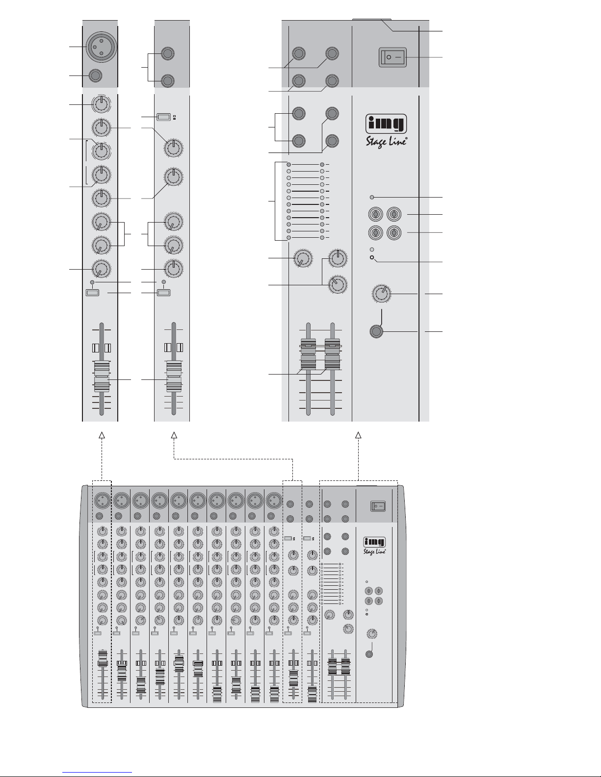
1 Übersicht der Bedienelemente und
Anschlüsse
Die Abbildungen 1–4 zeigen das Modell MMX-142.
Das Modell MMX-182 ist bis auf die Anzahl der
Mono-Eingangskanäle (14 x) vollkommen identisch.
1.1 Eingangskanäle
Abb. 1 Mono-Eingangskanal 1; die weiteren Mono-
Eingangskanäle sind identisch.
Abb. 2 Stereo-Eingangskanal 11/12 (bei MMX-142)
bzw. 15 /16 (bei MMX-182); der zweite Stereo-Eingangskanal ist identisch.
1 XLR-Buchse MIC (sym.) für den Anschluss eines
Mikrofons
Hinweis: Entweder ein Mikrofon an die XLRBuchse anschließen oder ein Gerät mit LinePegelausgang an die Klinkenbuchse LINE (3).
Hinweis: Die aktivierte Phantomspeisung kann
intern für einzelne Mono-Kanäle durch Entfernen
der Drahtbrücke LK1 abgeschaltet werden –
siehe dazu Kapitel 4.1.
2 Stereo-Eingang LEFT/RIGHT (6,3-mm-Klinke,
sym.) für den Anschluss einer Stereo-Signalquelle mit Line-Ausgangspegel (z. B. Mini-DiskRecorder, CD-Spieler, Keyboard)
Hinweis: Bei Monogeräten nur die obere Buchse
LEFT anschließen. Das Signal wird dann intern
auf den rechten und linken Kanal geschaltet.
3 6,3-mm-Klinkenbuchse LINE (sym.) für den An-
schluss eines Mono-Gerätes mit Line-Pegelausgang
Hinweis: Entwederein Gerät mit Line-Pegelausgang an die Klinkenbuchse anschließen oder
ein Mikrofon an die XLR-Buchse MIC (1).
4 Regler GAIN zum Einstellen der Eingangsver-
stärkung
5 Umschalttaste LEVEL zum Einstellen der Ein-
gangsverstärkung
Taste nicht gedrückt
niedrige Verstärkung für professionelle Geräte mit einem Ausgangspegel von +4dBu
(z.B. CD-Spieler)
Taste gedrückt
höhere Verstärkung für semiprofessionelle
Geräte mit einem Ausgangspegel von
-
10dBu
(z.B. Keyboard)
6 Klangregler HI (High) für die Höhen:
±15 dB /12 kHz
7 Regler zum Einstellen der Filterfrequenz (350 Hz–
6kHz) für die Klangregelung im Mittenbereich
8 Klangregler MID für die Mitten:
±15 dB / 350Hz –6kHz
9 Klangregler LO (Low) für die Bässe:
Monokanäle: ±15dB/60 Hz
Stereokanäle: ±15dB/45Hz
10 Regler AUX1 und AUX2 zum Mischen des Kanal-
signals auf die Auskoppelwege AUX 1 (postfader) und AUX 2 (pre-fader)
Die Signalauskoppelpunkte können intern für
jeden Kanal getrennt geändert werden, siehe
dazu Kapitel 4.2.
11 Panoramaregler PAN zum Platzieren des Mono-
Kanalsignals in der Stereo-Basis
12 Balanceregler BAL; ist nur die Buchse LEFT (2)
angeschlossen, arbeitet er als Panoramaregler
13 Anzeige PK
Ist die T aste PFL(14) nicht gedrückt, dient sie als
Übersteuerungsanzeige
kurzes Aufleuchten:
der Kanal ist maximal ausgesteuert und wird
gerade noch nicht übersteuert
leuchtet permanent:
der Kanal wird übersteuert; den Pegel mit dem
Regler GAIN (4) niedriger einstellen bzw. im
Stereo-Kanal die Taste LEVEL (5) ausrasten
Vorsicht! Keine asymmetrischen Mikrofone
anschließen, wenn die MikrofonPhantomspeisung eingeschaltet ist:
die gelbe LED PHANTOM POWER
+48V (29) leuchtet. Diese Mikrofone können beschädigt werden.
Please unfold page 3. Then you can always see the
operating elements and connections described.
Contents
1 Operating Elements and Connections . . . 4
1.1 Input channels . . . . . . . . . . . . . . . . . . . . . . . 4
1.2 Output section . . . . . . . . . . . . . . . . . . . . . . . 5
2 Safety Notes . . . . . . . . . . . . . . . . . . . . . . . . 5
3 Applications . . . . . . . . . . . . . . . . . . . . . . . . 6
4 Modification of the input channels . . . . . . 6
4.1 Switching off the phantom power
for individual microphone inputs . . . . . . . . . . 6
4.2 Modifying the signal take-off point of
the AUX send ways AUX 1 and AUX 2 . . . . . 6
5Rack installation for MMX-142 . . . . . . . . . . 7
6 Connecting Units . . . . . . . . . . . . . . . . . . . . 7
6.1 Microphones . . . . . . . . . . . . . . . . . . . . . . . . . 7
6.2 Units with line output . . . . . . . . . . . . . . . . . . 7
6.3 Effect units . . . . . . . . . . . . . . . . . . . . . . . . . . 7
6.3.1 Inserting an effect unit into
the master output . . . . . . . . . . . . . . . . . . . 7
6.3.2 Connecting effect units for the inputs . . . . 7
6.4 Recorder . . . . . . . . . . . . . . . . . . . . . . . . . . . . 8
6.5 Amplifiers . . . . . . . . . . . . . . . . . . . . . . . . . . . 8
6.6 Headphones . . . . . . . . . . . . . . . . . . . . . . . . . 8
6.7 Power supply . . . . . . . . . . . . . . . . . . . . . . . . 8
7 Operation . . . . . . . . . . . . . . . . . . . . . . . . . . . 8
7.1 Basic adjustment of the input channels . . . . 8
7.2 Mixing the input signals . . . . . . . . . . . . . . . . 9
7.3 Adjusting the AUX send ways . . . . . . . . . . . . 9
7.4 Monitoring the channels . . . . . . . . . . . . . . . . 9
8 Specifications . . . . . . . . . . . . . . . . . . . . . . . 9
9 Glossary . . . . . . . . . . . . . . . . . . . . . . . . . . 10
Block diagram . . . . . . . . . . . . . . . . . . . . . . . 25
1 Operating Elements and Connections
Figures 1 – 4 show model MMX-142. Model MMX182 is identical except for the number of the mono
input channels (14 x).
1.1 Input channels
Fig. 1 Mono input channel 1; the other mono input
channels are identical.
Fig. 2 Stereo input channel 11/12 (for MMX-142) or
15/16 (for MMX-182); the second stereo input channel is identical.
1 XLR jack MIC (bal.) for connecting a microphone
Note: Connect either a microphone to the XLR
jack or a unit with line level output to the jack
LINE (3).
Note: The activated phantom power can be
switched off internally for individual mono channels by removing the jumper LK1 – see chapter
4.1.
2 Stereo input LEFT/RIGHT (6.3mm jack, bal.) for
connecting a stereo signal source with line output level (e.g. minidisc recorder, CD player, keyboard)
Note: With mono units, only connect the upper
jack LEFT. The signal is then switched internally
to the right and left channels.
3 6.3 mm jack LINE (bal.) for connecting a mono
unit with line level output
Note: Connect either a unit with line level output
to the jack or a microphone to the XLR jack
MIC (1).
4 Control GAIN for adjusting the input amplification
5 Selector switch LEVEL for adjusting the input
amplification
button not pressed
low amplification for professional units with
an output level of +4dBu (e. g. CD player)
button pressed
higher amplification for semiprofessional units
with an output level of
-
10 dBu (e.g. key-
board)
6 Equalizer control HI (High) for the high frequen-
cies:
±15 dB / 12kHz
7 Control for adjusting the filter frequency (350 Hz
–6kHz) for the equalizer in the midrange
8 Equalizer control MID for the midrange:
±15 dB / 350Hz –6kHz
9 Equalizer control LO (Low) for the bass frequen-
cies:
mono channels: ±15dB/60 Hz
stereo channels: ±15dB/45 Hz
10 Controls AUX 1 and AUX 2 for mixing the chan-
nel signal to the AUX send ways AUX 1 (postfader) and AUX 2 (pre-fader)
The signal take-off points can be internally modified separately for each individual channel, see
chapter 4.2.
11 Panorama control PAN for placing the mono
channel signal in the stereo base
12 Balance control BAL; if only the jack LEFT (2) is
connected, it will operate as panorama control
13 LED PK
If the button PFL (14) is not pressed, it will serve
as overload indication
LED lights up shortly:
the channel is controlled to its maximum
level, just before being overloaded
LED lights permanently:
the channel is overloaded; reduce the level
with the control GAIN (4) or unlock the button
LEVEL (5) in the stereo channel
Caution! Do not connect any unbalanced
microphones with the microphone
phantom power switched on: the
yellow LED PHANTOM POWER
+48 V (29) lights up. These microphones may be damaged.
4
GB
D
A
CH

Ist die Taste PFL gedrückt, leuchtet die Anzeige
permanent und zeigt die aktivierte Vorhörfunktion an.
14 PFL-Taste zum V orhören des Kanals („Pre Fader
Listening“) über einen an der Buchse PHONES
(31) angeschlossenen Kopfhörer; bei gedrückter
Taste leuchtet die LED PK (13) permanent
15 Kanalfader zum Einstellen des Pegels, mit dem
das Kanalsignal auf die Ausgangssumme gemischt wird
1.2 Ausgangssektion (Abb. 3)
16 Buchsen BAL LEFT/RIGHT (sym.) für die Aus-
gangssumme
17 Buchsen SEND/RETURN zum Einschleifen eines
Effektgerätes in den linken und rechten Kanal der
Ausgangssumme (siehe auch Kapitel 6.3.1);
Steckeranschlüsse:
Spitze = Send (Ausgang)
Ring = Return (Eingang)
Schaft = Masse
18 Stereo-Zusatzeingang AUX INPUT (sym.) für
Geräte mit einem Line-Pegelausgang
Hinweis: Bei Monogeräten nur die obere Buchse
LEFT anschließen. Das Signal wird dann intern
auf den rechten und linken Kanal geschaltet.
19 Buchsen AUX SEND (asym.) für die Auskoppel-
wege AUX 1 und AUX 2
20 Aussteuerungsanzeige (Spitzenwertanzeige):
a) wenn keine der Tasten PFL(14) gedrückt ist,
wird der Pegel der Ausgangssumme an den
Buchsen BAL LEFT/RIGHT (16) post-fader
angezeigt
b) wenn eine oder mehrere Tasten PFL ge-
drückt sind, wird der zugehörige Pegel der
angewählten Kanäle pre-fader angezeigt
21 Regler AUX INPUT für den Pegel des Stereo-
Zusatzeingangs AUX INPUT[Buchsen (18)]
22 Summenregler AUX 1 SEND und AUX 2 SEND
für die Auskoppelwege [Buchsen (19)]
23 Fader für den Pegel der Ausgangssumme;
die Ausgangssumme liegt an den Buchsen OUTPUT BAL (16) an und an der Buchse TAPE
REC (27)
24 Netzbuchse zum Anschluss an eine Steckdose
(230V~/50Hz) über das beiliegende Netzkabel;
darunter befindet sich der Sicherungshalter; eine
durchgebrannte Netzsicherung nur durch eine
gleichen Typs ersetzen
25 Ein-/Ausschalter POWER
26 Betriebsanzeige POWER
27 Ausgangsbuchsen TAPE REC (Cinch, asym.)
zum Anschluss eines Aufnahmegerätes: hier
liegt die Ausgangssumme an (post-fader)
28 Wiedergabeeingang TAPE PLAY (Cinch, asym.)
zum Anschluss an den Ausgang eines Tonaufnahmegerätes;
das Eingangssignal wird vor den Fadern L und R
(23) auf die Ausgangssumme gegeben
29 versenkter Schalter (mit gelber Kontroll-LED)
zum zentralen Zuschalten der 48-V-Phantomspeisung für die XLR-Buchsen MIC (1);
erforderlich beim Anschluss von Kondensatoroder Elektretmikrofonen, die mit 48-V-Phantomspeisung arbeiten
Vorsicht!Den Schalter nur bei ausgeschaltetem
Mischpult betätigen, um Schaltgeräusche zu vermeiden. Bitte beachten Sie auch den grau hinterlegten Hinweis der Position 1!
30 Lautstärkeregler PHONES für einen an der dar-
unter liegenden Buchse angeschlossenen Kopfhörer
31 6,3-mm-Klinkenbuchse PHONES zum Anschluss
eines Stereo-Kopfhörers (Impedanz ≥ 32 Ω);
a) wenn keine der Tasten PFL(14) gedrückt ist,
lässt sich das Signal der Ausgangssumme
post-fader abhören
b) wenn eine oder mehrere Tasten PFL ge-
drückt sind, können die angewählten Kanäle
vorgehört (pre-fader) werden
2 Hinweise für den sicheren Gebrauch
Dieses Gerät entspricht der Richtlinie für elektromagnetische Verträglichkeit 89/ 336/ EWG und der
Niederspannungsrichtlinie 73/23/EWG.
Beachten Sie auch unbedingt die folgenden Punkte:
●
Verwenden Sie das Gerät nur im Innenbereich.
Schützen Sie es vor Tropf- und Spritzwasser,
hoher Luftfeuchtigkeit und Hitze (zulässiger Einsatztemperaturbereich 0– 40°C).
●
Stellen Sie keine mit Flüssigkeit gefüllten Gefäße,
z.B. Trinkgläser, auf das Gerät.
●
Nehmen Sie das Gerät nicht in Betrieb bzw. ziehen Sie sofort den Netzstecker, wenn:
1. sichtbare Schäden am Gerät oder an der Netzanschlussleitung vorhanden sind,
2. nach einem Sturz oder Ähnlichem der Verdacht
auf einen Defekt besteht,
3. Funktionsstörungen auftreten.
Geben Sie das Gerät in jedem Fall zur Reparatur
in eine Fachwerkstatt.
●
Verwenden Sie für die Reinigung nur ein trockenes, weiches Tuch, auf keinen Fall Chemikalien
oder Wasser.
●
Ziehen Sie den Netzstecker nie an der Zuleitung
aus der Steckdose, fassen Sie immer am Stecker
an!
●
Wird das Gerät zweckentfremdet, falsch bedient
oder nicht fachgerecht repariert, kann für eventuelle
Schäden keine Haftung übernommen werden.
●
Soll das Gerät endgültig aus dem Betrieb genommen werden, übergeben Sie es zur umweltgerechten Entsorgung einem örtlichen Recyclingbetrieb.
Achtung! Das Gerät wird mit lebensgefährlicher
Netzspannung (230 V~) versorgt. Nehmen Sie deshalb nie selbst Eingriffe im
Gerät vor. Durch unsachgemäßes Vorgehen besteht die Gefahr eines elektrischen Schlages. Außerdem erlischt
beim Öffnen des Gerätes jeglicher
Garantieanspruch.
If the button PFL is pressed, the LED will light
permanently and indicate the activated prefader
listening facility.
14 PFL button for prefader listening to the channel
via headphones connected to the jack PHONES
(31); with the button pressed, the LED PK (13)
will light permanently
15 Channel fader for adjusting the level at which the
channel signal is mixed to the master output
1.2 Output section (fig. 3)
16 Jacks BAL LEFT/ RIGHT (bal.) for the master
output
17 Jacks SEND/RETURN for inserting an effect
unit into the left and right channels of the master
output (also see chapter 6.3.1);
plug connections:
tip = send (output)
ring = return (input)
body = ground
18 Additional stereo input AUX INPUT (bal.) for
units with a line level output
Note: With mono units, only connect the upper
jack LEFT. The signal is then switched internally
to the right and left channels.
19 Jacks AUX SEND (unbal.) for the AUX send
ways AUX 1 and AUX 2
20 VU-meter (peak value indication):
a) with none of the buttons PFL (14) pressed,
the level of the master output at the jacks BAL
LEFT/RIGHT (16) is indicated post-fader
b) with one or several buttons PFL pressed, the
corresponding level of the selected channels
is indicated prefader
21 Control AUX INPUT for the level of the additional
stereo input AUX INPUT[jacks (18)]
22 Master controls AUX 1 SEND and AUX 2 SEND
for the AUX send ways [jacks (19)]
23 Faders for the level of the master output;
the master output is available at the jacks OUTPUT BAL (16) and at the jack TAPE REC (27)
24 Mains jack for connection to a socket (230 V~ /
50 Hz) via the supplied mains cable; the fuse
holder is below this jack; replace a burnt-out fuse
by one of the same type only
25 POWER switch
26 POWER LED
27 Output jacks TAPE REC (phono, unbal.) for
connecting a recorder: the master output is available at these jacks (post-fader)
28 Replay input TAPE PLAY (phono, unbal.) for
connecting the output of an audio recorder;
the input signal is sent to the master output
ahead of the faders L and R (23)
29 Recessed switch (with yellow indicating LED) for
central connection of the 48V phantom power for
the XLR jacks MIC (1);
required when connecting capacitor microphones
or electret microphones operating at a 48V phantom power
Caution! Only actuate the switch with the mixer
switched off to prevent switching noise. Please
also observe the note with the grey background
in position 1!
30 Volume control PHONES for headphones
connected to the jack below
31 6.3 mm jack PHONES for connecting stereo
headphones (impedance ≥ 32 Ω);
a) with none of the buttons PFL (14) pressed,
the signal of the master output can be monitored post-fader
b) with one or several of the buttons PFL
pressed, prefader listening to the selected
channels is possible
2 Safety Notes
This unit corresponds to the directive for electromagnetic compatibility 89/ 336 /EEC and to the low
voltage directive 73/23/EEC.
Please observe the following items in any case:
●
The unit is suitable for indoor use only. Protect it
against dripping water and splash water, high air
humidity, and heat (admissible ambient temperature range 0– 40°C).
●
Do not place any vessel filled with liquid on the
unit, e.g. a drinking glass.
●
Do not operate the unit or immediately disconnect
the plug from the mains socket
1. if there is visible damage to the unit or to the
mains cable,
2. if a defect might have occurred after the unit
was dropped or suffered a similar accident,
3. if malfunctions occur.
In any case the unit must be repaired by skilled
personnel.
●
For cleaning only use a dry, soft cloth, by no
means chemicals or water.
●
Never pull the mains cable when disconnecting
the mains plug from the socket, always seize the
plug!
●
No liability for any damage will be accepted if the
unit is used for other purposes than originally intended, if it is not correctly operated or not repaired in an expert way.
●
If the unit is to be put out of operation definitively,
take it to a local recycling plant for a disposal
which is not harmful to the environment.
Attention!The unit is supplied with hazardous
mains voltage (230 V~). Leave servicing to skilled personnel only. Inexpert
handling may cause an electric shock
hazard. Furthermore, any guarantee
claim will expire if the unit has been
opened.
5
GB
D
A
CH
3 Einsatzmöglichkeiten
Die Mischpulte MMX-142 und MMX-182 sind speziell für Musiker und den Einsatz auf der Bühne ausgelegt. 10 Mono- (14 bei MMX-182) und 2 StereoEingangskanäle lassen sich auf die Ausgangssumme mischen. Jeder Eingangskanal befindet sich
auf einer separaten Leiterplatte (Modular PCB
Design) und ist mit diversen Einstellmöglichkeiten
ausgestattet, z.B.:
– Gain-Regler
(bei den Stereo-Kanälen Level-Schalter)
– für die Mikrofoneingänge zuschaltbare Phantom-
speisung von +48V
– In den Mono-Kanälen 3fach-Klangregelung mit
einstellbarer Mittenfrequenz
– 2 Auskoppel-Regler, Signalauskoppelpunkt intern
durch Steckbrücke wählbar pre-/post-fader;
für AUX 2 auch pre-equalizer
– Panorama- bzw. Balanceregler
– LED für Peak- und PFL-Anzeige
Die Eingangskanäle und die Ausgangssumme können über einen Kopfhörer abgehört werden.
4 Modifikation der Eingangskanäle
Bei Bedarf vor dem Anschluss des Mischpults die
folgenden Modifikationen in den Eingangskanälen
durchführen.
1) Zuerst unbedingt den Netzstecker aus der Steckdose ziehen.
2) Die beiden Seitenteile abschrauben.
3) Jeweils die 3 Kreuzschlitzschrauben an den Seiten und der Stirnseite entfernen sowie die
4 Schrauben an der Rückseite. Die Bodenplatte
abnehmen.
4) Die Modifikationen nach Kapitel 4.1 und/oder 4.2
durchführen.
5) Das Mischpult wieder zusammenschrauben.
4.1 Phantomspeisung für einzelne Mikrofon-
eingänge abschalten
Die 48-V-Phantomspeisung für die Buchsen MIC (1)
ist zentral zuschaltbar, kann jedoch für jeden MonoKanal einzeln abgeschaltet werden, wenn sowohl
asymmetrische als auch phantomgespeiste Mikrofone angeschlossen werden sollen.
Zum Abschalten der Phantomspeisung auf der
Platine des betreffenden Kanals die Drahtbrücke
LK1 durchtrennen (siehe Abb. 5).
4.2 Signalauskoppelpunkt der Auskoppel-
wege AUX1 und AUX2 ändern
1. Für den Weg AUX 1 wird das Signal post-fader
ausgekoppelt. Durch Umstecken der Brücke JP1
für jeden Kanal getrennt lässt es sich auch prefader abnehmen – siehe Abb. 5.
2. Für den Weg AUX 2 kann der Signalauskoppel-
punkt durch Umstecken der Brücke JP2 für jeden
Kanal getrennt von pre-fader auf pre-equalizer
oder post-fader umgestellt werden – siehe Abb. 5.
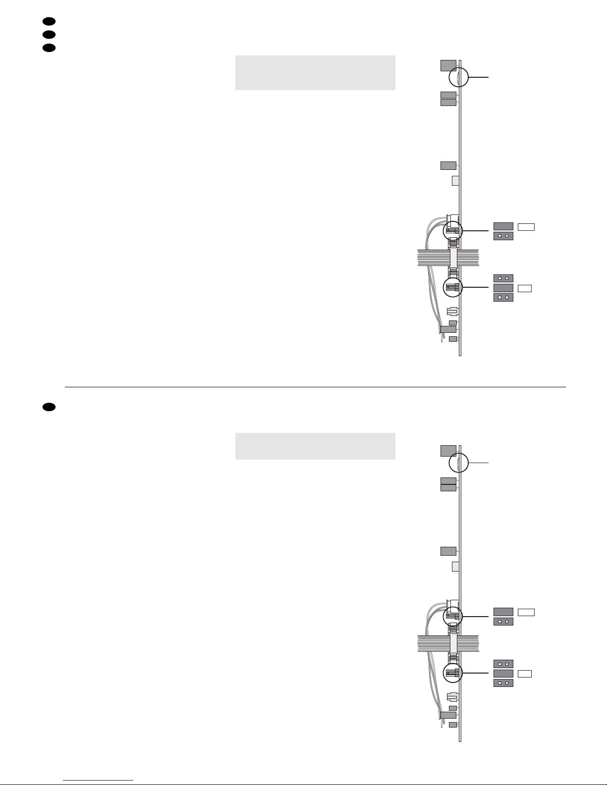
➄ Leiterplatte eines Eingangskanals
LK1
JP1
POST
PRE
JP2
POST
PREEQ
PRE
AUX1
AUX2
Vorsicht! Für diese Änderungen muss das Gerät
geöffnet werden. Darum dürfen sie nur
von einer qualifizierten Fachkraft durchgeführt werden.
●
Important for U.K. Customers!
The wires in this mains lead are coloured in
accordance with the following code:
blue = neutral
brown = live
As the colours of the wires in the mains lead of this
appliance may not correspond with the coloured
markings identifying the terminals in your plug,
proceed as follows:
1. The wire which is coloured blue must be connected to the terminal in the plug which is
marked with the letter N or coloured black.
2. The wire which is coloured brown must be connected to the terminal which is marked with the
letter L or coloured red.
3 Applications
The mixers MMX-142 and MMX-182 are specially
designed for musicians and stage applications. 10
mono input channels (14 for MMX-182) and 2 stereo
input channels can be mixed to the master output.
Each input channel is situated on a separate PCB
(modular PCB design) and offers various adjusting
facilities, e.g.:
– gain control (selector switch for the level of the
stereo channels)
– +48 V phantom power to be connected for the
microphone inputs
– 3-way equalizer with adjustable midrange in the
mono channels
– 2 AUX controls, signal take-off point to be inter-
nally selected (prefader/ post-fader) by jumper;
for AUX 2 also pre-equalizer
– panorama or balance control
– peak and PFL LEDs
The input channels and the master output can be
monitored via headphones.
4 Modification of the Input Channels
If required, perform the following modifications of the
input channels prior to connecting the mixer.
1) Always disconnect the mains plug from the
socket first.
2) Unscrew the two side parts.
3) Remove the 3 recessed head screws each on the
sides and on the face and the 4 screws on the
rear side. Remove the bottom plate.
4) Perform the modifications according to chapter
4.1 and/or 4.2.
5) Reassemble the mixer.
4.1 Switching off the phantom power for indi-
vidual microphone inputs
The 48V phantom power for the jacks MIC (1) can
be centrally connected, however, it can be individually disconnected for each mono channel for
connecting both unbalanced and phantom-powered
microphones.
For disconnecting the phantom power, separate
the jumper LK1 on the PCB of the corresponding
channel (see fig. 5).
4.2 Modifying the signal take-off point of the
AUX send ways AUX 1 and AUX 2
1. For the way AUX 1, the signal is taken off postfader. By rearranging the jumper JP1 separately
for each channel, it can also be taken off prefader
– see fig. 5.
2. For the way AUX 2, the signal take-off point can
be changed from prefader to pre-equalizer or
post-fader, separately for each channel, by rearranging the jumper JP2 – see fig. 5.
➄ PCB of an input channel
LK1
JP1
POST
PRE
JP2
POST
PREEQ
PRE
AUX1
AUX2
Caution! For these modifications, the unit must be
opened. Therefore, they may only be
performed by qualified, skilled personnel.
6
GB
D
A
CH
5 Rack-Montage für MMX-142
Das Mischpult MMX-142 lässt sich sowohl als Tischgerät verwenden als auch in ein Rack (482 mm/19")
einbauen.
1) Für den Rackeinbau die beiden Seitenteile
abschrauben.
2) Jeweils die 3 Kreuzschlitzschrauben an den Seiten abschrauben. Die Schrauben und Seitenteile
aufbewahren, wenn das Gerät später wieder als
Tischgerät betrieben werden soll.
3) Die beiden beiliegenden Seitenwinkel mit den
beiliegenden längeren Schrauben (M3 x 8 mm)
seitlich festschrauben. Die längeren Schrauben
nur für die Winkelbefestigung verwenden, anderenfalls wird das Gerät beschädigt.
6 Geräte anschließen
Vor dem Anschließen von Geräten bzw. Ändern bestehender Anschlüsse das Mischpult und alle anderen Audiogeräte ausschalten.
6.1 Mikrofone
1) Benötigen die verwendeten Mikrofone keine
Phantomspeisung, den versenken Schalter
PHANTOM POWER +48 V (29) nicht drücken.
Nach dem Einschalten des Mischpults darf die
darüber liegende gelbe LED nicht leuchten. In
diesem Fall können sowohl symmetrisch als
auch asymmetrisch beschaltete Mikrofone angeschlossen werden.
2) Für den Betrieb von phantomgespeisten Mikrofonen den Schalter PHANTOM POWER +48V mit
einem dünnen Gegenstand (z.B. Kugelschreiber,
Schraubendreher) hineindrücken. Nach dem Einschalten des Mischpults leuchtet die darüber liegende gelbe LED. An allen XLR-Buchsen MIC (1)
liegt die 48-V-Phantomspeisung an.
Die Phantomspeisung lässt sich für einzelne
Kanäle abschalten. Siehe dazu Kapitel 4.1.
3) Die Mikrofone an die XLR-Buchsen MIC (1) anschließen.
Hinweis: Es kann nicht zwischen den XLR-Buchsen
MIC und den Klinkenbuchsen LINE (3) umgeschaltet werden. Darum in jedem Kanal entweder ein
Mikrofon an die Buchse MIC anschließen oder ein
Gerät mit Line-Pegelausgang an die Buchse LINE.
6.2 Geräte mit Line-Ausgang
Signalquellen mit Line-Monoausgang (z.B. Instrumente) an die Buchsen LINE (3) anschließen. Beim
Anschluss von Mono-Geräten an die Stereo-Kanäle
jeweils nur die Buchse LEFT (2) anschließen. Das
Eingangssignal wird dann intern auf den rechten und
linken Kanal geschaltet.
Stereo-Geräte an die Buchsen LEFT und RIGHT
(2) anschließen. Außerdem können die Buchsen AUX
INPUT (18) im Ausgangsfeld verwendet werden.
Hinweis: In jedem Kanal entweder ein Mikrofon an
die Buchse MIC anschließen oder ein Gerät mit
Line-Pegelausgang an die Buchse LINE.
6.3 Effektgeräte
6.3.1 Effektgerät in die Ausgangssumme ein-
schleifen
Ein Effektgerät lässt sich direkt in die Ausgangssumme einschleifen, wobei das zu bearbeitende
Signal komplett über das Effektgerät läuft (z. B. bei
Kompressoren, Noise-Gates, Equalizern). Das
Effektgerät an die Buchsen SEND/ RETURN (17)
anschließen. Die benötigten Stecker müssen wie
folgt angeschlossen sein:
Spitze = Send (Ausgang)
Ring = Return (Eingang)
Schaft = Masse
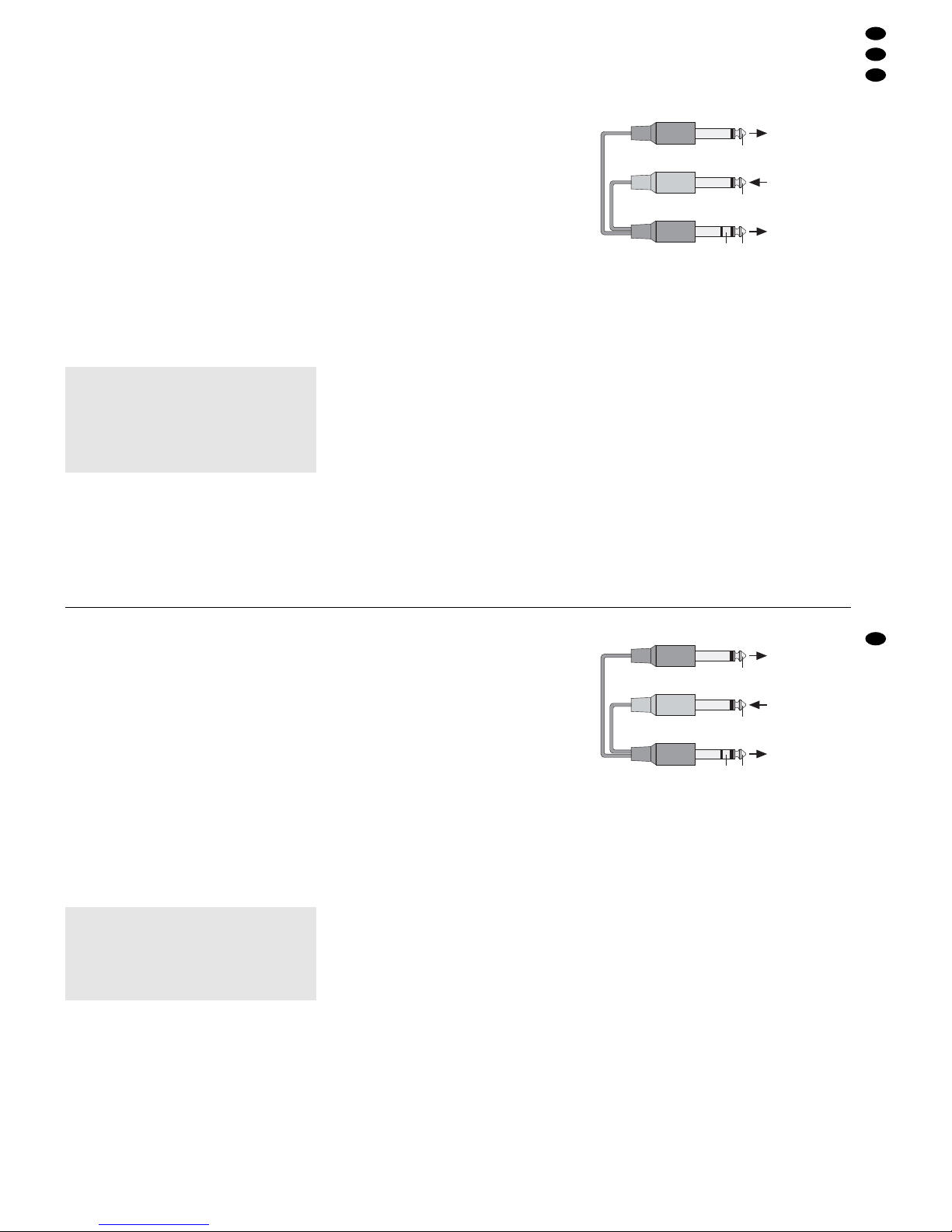
Zum Anschluss von Effektgeräten mit getrennten Einund Ausgangsbuchsen werden Y-Kabel benötigt,
z.B. MCA-202 aus dem Sortiment von MONACOR:
➅ Anschluss des Y-Kabels MCA-202 von MONACOR
6.3.2 Effektgeräte für die Eingänge anschließen
Über den Regler AUX 1 (10) können Signalanteile
post-fader aus den Eingangskanälen ausgekoppelt,
über ein Effektgerät geführt und nach der Bearbeitung über einen Eingangskanal oder den Eingang
AUX INPUT (18) auf die Ausgangssumme dazugemischt werden (z.B. bei Hallgeräten).
1) Den Eingang des Effektgerätes an den Ausgang
AUX SEND 1 (19) anschließen.
2) Den Ausgang des Effektgerätes an einen freien
Eingang LINE (3) oder LEFT/RIGHT (2) anschließen. Zum Anschluss des Effekgeräteausgangs kann auch der Zusatzeingang AUX INPUT
(18) genutzt werden.
3) Werden zwei unterschiedliche Effektsignale benötigt, kann der Auskoppelweg AUX 2 nach
Modifikation, wie im Kap. 4.2 beschrieben, ebenfalls als Effektweg genutzt werden. Den Eingang
des zweiten Effektgeräts dann an den Ausgang
AUX SEND 2 (19) anschließen und den Effektgeräteausgang an einen weiteren freien Eingangskanal.
Mischpult
SEND/RETURN
Eingang
Effektgerät
Ausgang
Effektgerät
RETURN SEND
RETURN
SEND
rot
schwarz
schwarz
Vorsicht! Die Phantomspeisung nur bei ausge-
schaltetem Mischpult dazu- oder abschalten, sonst entstehen laute Schaltgeräusche.
An die phantomgespeisten XLR-Buchsen MIC (1) keine asymmetrischen
Mikrofone anschließen. Diese können
beschädigt werden.
5 Rack Installation for MMX-142
The mixer MMX-142 can either be used as a tabletop unit or be installed into a rack (482mm/19").
1) For rack installation, unscrew the two side parts.
2) Unscrew the 3 recessed head screws each on the
sides. Keep the screws and the side parts in case
the unit will be used as a table-top unit again later.
3) Fasten the two supplied lateral angles with the
supplied long screws (M3 x 8 mm) to the sides.
Only use the long screws for fixing the angles,
otherwise the unit will be damaged.
6 Connecting Units
Prior to connecting any units or to changing existing
connections, switch off the mixer and all other audio
units.
6.1 Microphones
1) If the microphones used do not require phantom
power, do not press the recessed switch PHANTOM POWER +48V (29). After switching on the
mixer, the yellow LED above the switch must not
light up. In this case, both balanced and unbalanced microphones can be connected.
2) For operating phantom-powered microphones,
press the switch PHANTOM POWER +48 V by
means of a thin object (e.g. ball point pen, screwdriver). After switching on the mixer, the yellow
LED above the switch will light up. The 48V phantom power is available at all XLR jacks MIC (1).
The phantom power can be switched off for
individual channels. See chapter 4.1.
3) Connect the microphones to the XLR jacks MIC
(1).
Note: It is impossible to switch from the XLR jacks
MIC to the jacks LINE (3) and vice versa. Therefore,
in each channel, either connect a microphone to the
jack MIC or a unit with line level output to the jack
LINE.
6.2 Units with line output
Connect signal sources with line mono output (e.g.
musical instruments) to the jacks LINE (3). When
connecting mono units to the stereo channels, only
connect the jack LEFT (2) each. The input signal is
then switched internally to the right and left channels.
Connect stereo units to the jacks LEFT and
RIGHT (2). Besides, the jacks AUX INPUT (18) can
be used in the output section.
Note: In each channel, either connect a microphone
to the jack MIC or a unit with line level output to the
jack LINE.
6.3 Effect units
6.3.1 Inserting an effect unit into the master output
An effect unit can be directly inserted into the master
output in which case the signal to be processed is
completely routed via the effect unit (e. g. for compressors, noise gates, equalizers). Connect the
effect unit to the jacks SEND / RETURN (17). The
required plugs must be connected as follows:
tip = send (output)
ring = return (input)
body = ground
For connecting effect units with separate input jacks
and output jacks, Y-cables are required, e.g. MCA202 from the MONACOR range:
➅ Connection of the MONACOR Y-cable MCA-202
6.3.2 Connecting effect units for the inputs
Via the control AUX 1 (10), it is possible to take off
signal parts post-fader from the input channels, route
them via an effect unit and, after processing, mix
them to the master output via an input channel or the
input AUX INPUT(18) [e. g. for reverberation units].
1) Connect the input of the effect unit to the output
AUX SEND 1 (19).
2) Connect the output of the effect unit to an unconnected input LINE (3) or LEFT/ RIGHT (2).
The additional input AUX INPUT(18) can also be
used for connecting the effect unit output.
3) If two different effect signals are required, the
AUX send way AUX 2 can also be used as an
effect way after modification as described in
chapter 4.2. Then connect the input of the second effect unit to the output AUX SEND 2 (19)
and connect the output of the effect unit to another unconnected input channel.
mixer
SEND/RETURN
input
of effect unit
output
of effect unit
RETURN SEND
RETURN
SEND
red
black
black
Caution! Only switch on or off the phantom power
with the mixer switched off, otherwise
there will be loud switching noises.
Do not connect any unbalanced microphones to the phantom-powered XLR
jacks MIC (1); these microphones may
be damaged.
7
GB
D
A
CH

6.4 Aufnahmegerät
Ein Aufnahmegerät kann an den Ausgang T APE REC
(27) angeschlossen werden. Hier liegt die Ausgangssumme abhängig von den Summenfadern R und L
(23) an.
Nach der Aufnahme lässt sich diese über das
Mischpult wiedergeben. Dazu den Ausgang des Aufnahmegerätes an die Cinch-Buchsen TAPE PLAY
(28) anschließen. Das Signal wird vor den Summenfadern L und R auf die Ausgangssumme gegeben.
Darum zur Wiedergabe einer Aufnahme alle Kanalfader (15) zuziehen.
6.5 Verstärker
1) Den Verstärker, auf den die Ausgangssumme
gegeben werden soll (z. B. für die Saalbeschal-
lung), an die Buchsen BAL RIGHT/LEFT (16) an-
schließen.
2) Über den Auskoppelweg AUX2, der vom Herstel-
ler pre-fader geschaltet ist, können die Musiker
ein separat abgemischtes Musiksignal über eine
Monitoranlage auf der Bühne zugespielt bekom-
men. Den Verstärker für diese Bühnenbeschallung
an den Ausgang AUX SEND 2 (19) anschließen.
3) Werden zwei unterschiedliche Monitorsignale
benötigt, kann der Auskoppelweg AUX 1 nach
Modifikation, wie im Kap. 4.2 beschrieben, eben-
falls zur Bühnenbeschallung genutzt werden.
Den zweiten Verstärker zur Bühnenbeschallung
dann an den Ausgang AUX SEND 1 (19) an-
schließen.
6.6 Kopfhörer
Zur Kontrolle oder zur Einpegelung lassen sich einzelne oder auch mehrere Eingangssignale über
einen Stereo-Kopfhörer (Impedanz ≥ 32Ω) vor den
zugehörigen Kanalfadern (15) abhören oder die
Ausgangssumme nach den Summenfadern (23) –
siehe auch Kapitel 7.4 „Abhören der Kanäle“. Dazu
den Kopfhörer an die Buchse PHONES (31) anschließen.
6.7 Stromversorgung
Nachdem alle anderen Anschlüsse hergestellt sind,
das beiliegende Netzanschlusskabel zuerst in die
Netzbuchse (24) auf der Mischpultrückseite stecken
und dann in eine Steckdose (230V~/50Hz).
7Bedienung
Vor dem Einschalten sollten die Fader Lund R (23)
für die Ausgangssumme und die Summenregler
AUX 1 SEND und AUX 2 SEND (22) der Auskoppelwege auf Minimum gestellt werden, um Einschaltgeräusche zu vermeiden. Dann das Mischpult mit dem
Schalter POWER (25) einschalten. Die Betriebsanzeige POWER (26) leuchtet. Anschließend die
angeschlossenen Geräte einschalten.
Nach dem Betrieb das Mischpult wieder mit dem
Schalter POWER (25) ausschalten.
7.1 Grundeinstellung der Eingangskanäle
1) Zur Vorbereitung
a zunächst die folgenden Regler in die Mittel-
stellung drehen
in den Mono-Kanälen:
die Regler GAIN (4) für die Vorverstärkung,
die Klangregler HI (6), MID (7, 8) und LO (9),
die Panoramaregler PAN (11);
in den Stereo-Kanälen:
die Klangregler HI (6) und LO (9),
die Balanceregler BAL (12).
b In allen Kanalzügen die Pegelregler AUX 1
und AUX2 (10) für die Auskoppelwege auf
Null drehen.
c Die Tasten PFL(14) in allen Eingangskanälen
sowie die Tasten LEVEL (5) in den StereoKanälen dürfen nicht gedrückt sein.
dVorerst die Kanalfader (15) ganz zuziehen.
2) Ein Tonsignal (Testsignal oder Musikstück) auf
den ersten verwendeten Kanal geben.
3) Damit ein Signal über die angeschlossene Audioanlage gehört werden kann, zunächst den
zugehörigen Kanalfader (15) auf ca. 0dB schieben. Die Fader L und R (23) für die Ausgangssumme so weit aufziehen, dass das Signal zu
hören ist. Das Signal lässt sich auch über einen
Kopfhörer kontrollieren – siehe dazu Kapitel 7.4
„Abhören der Kanäle“.
4) Die Taste PFL (14) des einzustellenden Kanals
drücken, die anderen T asten PFLmüssen ausgerastet sein. Die rote LED PK (13) über der gedrückten Taste PFL leuchtet kontinuierlich. Die
Aussteuerungsanzeige (20) zeigt den Pegel vor
dem Fader des gewählten Kanalzugs an.
5) In den Mono-Kanälen mit dem zugehörigen Regler GAIN (4) anhand der Aussteuerungsanzeige
den Eingang optimal einpegeln: Bei lauten Passagen sollte die grüne LED „0 dB“ aufleuchten.
Falls erforderlich, kann der Regler auch ganz
nach links oder rechts gedreht werden.
Wird ein Stereo-Kanal trotz ausgerasteter
Taste LEVEL (5) übersteuert, muss der Pegel der
Signalquelle verringert werden. Bei geringer Aussteuerung des Kanals lässt sich der Pegel durch
Drücken der Taste LEVEL um 14dB anheben.
Wird die Taste PFL wieder ausgerastet, lässt
sich die Aussteuerung mit der roten LED PK (13)
grob kontrollieren: Bei Übersteuerung leuchtet
sie permanent auf. Dann den Regler GAIN entsprechend zurückdrehen. Leuchtet die LED nur
kurz auf, ist der Kanal maximal ausgesteuert.
6) Den Klang mit den Reglern HI (6) für die Höhen,
und LO (9) für die Bässe einstellen (±15 dB). In
Vorsicht! Stellen Sie die Lautstärke der Audio-
anlage und die Kopfhörerlautstärke nie
sehr hoch ein. Hohe Lautstärken können auf Dauer das Gehör schädigen!
Das menschliche Ohr gewöhnt sich an
große Lautstärken und empfindet sie
nach einiger Zeit als nicht mehr so
hoch. Darum eine hohe Lautstärke nach
der Gewöhnung nicht weiter erhöhen.
6.4 Recorder
A recorder can be connected to the output TAPE
REC (27). This is where the master output is available depending on the master faders R and L (23).
The recording can be replayed via the mixer. For
this purpose, connect the output of the recorder to
the phono jacks TAPE PLAY (28). The signal is fed
to the master output ahead of the master faders R
and L. Therefore, close all channel faders (15) when
replaying a recording.
6.5 Amplifiers
1) Connect the amplifier to which the master output
is to be fed (e.g. for PAapplication in halls) to the
jacks BAL RIGHT/LEFT (16).
2) The AUX send way AUX 2 which is factory-set to
prefader allows the musicians on stage to receive
a separately mixed music signal from a monitor-
ing system. Connect the amplifier for this stage
PA application to the output AUX SEND 2 (19).
3) If two different monitoring signals are required, the
AUX send way AUX 1 can also be used for PA
stage application after modification as described in
chapter 4.2. Then connect the second amplifier for
PA stage application to the output AUX SEND 1
(19).
6.6 Headphones
As a check or for level control, it is possible to monitor individual or several input signals via stereo
headphones (impedance ≥ 32Ω) ahead of the corresponding channel faders (15) or the master output
after the master faders (23) – also see chapter 7.4
“Monitoring the channels”. For this purpose, connect
the headphones to the jack PHONES (31).
6.7 Power supply
After all other connections have been made,
connect the supplied mains cable first to the mains
jack (24) on the rear side of the mixer and then to a
mains socket (230 V~/50 Hz).
7 Operation
Prior to switching on, it is recommended to set the
faders L and R (23) for the master output and the
master controls AUX 1 SEND and AUX 2 SEND (22)
of the AUX send ways to minimum to prevent
switching noise. Switch on the mixer with the
POWER switch (25). The POWER LED (26) lights
up. Then switch on the connected units.
After operation, switch off the mixer with the
POWER switch (25).
7.1 Basic adjustment of the input channels
1) Preparation
a first set the following controls to mid-position
for the mono channels:
the controls GAIN (4) for preamplification,
the equalizer controls HI (6), MID (7, 8), and
LO (9),
the panorama controls PAN (11);
for the stereo channels:
the tone controls HI (6) and LO (9),
the balance controls BAL (12).
b In all channels, set the level controls AUX 1
and AUX 2 (10) for the AUX send ways to zero.
c The buttons PFL(14) in all input channels and
the buttons LEVEL (5) in the stereo channels
must not be pressed.
d For the time being, completely close the chan-
nel faders (15).
2) Feed an audio signal (test signal or music piece)
to the first channel used.
3) For hearing a signal via the connected audio system, first set the corresponding channel fader (15)
to approx. 0dB. Advance the faders L and R (23)
for the master output until the signal is audible.
The signal can also be checked via headphones –
also see chapter 7.4 “Monitoring the channels”.
4) Press the button PFL (14) of the channel to be
adjusted, all other PFL buttons must be unlocked.
The red LED PK (13) above the PFL button
pressed will light permanently. The VU-meter (20)
indicates the level ahead of the fader of the
selected channel.
5) In the mono channels, adjust the input to an optimum level with the corresponding control GAIN
(4) by means of the VU-meter: The green LED
“0 dB” should light up with music peaks. If required, the control can also be fully turned to the
left or right stop.
If a stereo channel is overloaded despite the
button LEVEL (5) being unlocked, reduce the
level of the signal source. In case of low level
control of the channel, the level can be boosted
by 14dB by pressing the button LEVEL.
With the button PFL being unlocked again, the
level control can be checked coarsely with the red
LED PK (13): In case of overload, it will light permanently. In this case, turn back the control GAIN
correspondingly. If the LED lights up only shortly,
the channel is controlled to its maximum level.
6) Adjust the sound with the controls HI (6) for the
high frequencies and LO (9) for the bass frequencies (±15dB). In the mono channels, adjust
the midrange with the upper control MID (7) between 350Hz and 6 kHz, then adjust the boosting
or reduction of the midrange (±15 dB) with the
lower control MID (8). After that, check the level
of the channel and readjust it, if required.
7) Place the mono channel signal in the stereo base
with the control PAN (11) or adjust the balance in
the stereo channel with the control BAL (12).
8) Close the channel fader (15) again to ensure that
the signal of the first channel will not interfere
when adjusting the next channel. Unlock the corresponding button PFL again. Repeat the adjustments of level, sound, and panorama or balance
for all other channels.
Caution! Do not adjust the audio system or the
headphones to a very high volume. Permanent high volumes may damage your
hearing! The human ear will get accustomed to high volumes which do not
seem to be that high after some time.
Therefore, do not further increase a high
volume after getting used to it.
8
GB
D
A
CH
 Loading...