

12-KANAL-AUDIOMISCHPULT
12-CHANNEL AUDIO MIXER
TABLE DE MIXAGE AUDIO 12 CANAUX
MIXER AUDIO A 12 CANALI
MMX-1202 Best.-Nr. 20.2110
BEDIENUNGSANLEITUNG • INSTRUCTION MANUAL • MODE D’EMPLOI
ISTRUZIONI PER L’USO • GEBRUIKSAANWIJZING • MANUAL DE INSTRUCCIONES • INSTRUKCJA OBSŁUGI
SIKKERHEDSOPLYSNINGER • SÄKERHETSFÖRESKRIFTER • TURVALLISUUDESTA

2
wwwwww..iimmggssttaaggeelliinnee..ccoomm
Bevor Sie einschalten ...
Wir wünschen Ihnen viel Spaß mit Ihrem neuen Gerät von
„img Stage Line“. Dabei soll Ihnen diese Bedienungsanleitung helfen, alle Funktionsmöglichkeiten kennen zu lernen. Die Beachtung der Anleitung vermeidet außerdem
Fehlbedienungen und schützt Sie und Ihr Gerät vor eventuellen Schäden durch unsachgemäßen Gebrauch.
Den deutschen Text finden Sie auf den Seiten 4– 12.
Before you switch on ...
We wish you much pleasure with your new “img Stage
Line” unit. With these operating instructions you will be
able to get to know all functions of the unit. By following
these instructions false operations will be avoided, and
possible damage to yourself and your unit due to improper use will be prevented.
You will find the English text on the pages 4–12.
D
A
CH
GB
Voordat u inschakelt ...
Wij wensen u veel plezier met uw nieuw toestel van “img
Stage Line”. Met behulp van bijgaande gebruiksaanwijzing kunt u alle functiemogelijkheden leren kennen.
Door deze instructies op te volgen zal een slechte werking vermeden worden, en zal een eventueel letsel aan
uzelf en schade aan uw toestel tengevolge van onzorgvuldig gebruik worden voorkomen.
U vindt de nederlandstalige tekst op de pagina’s 22– 30.
Antes de cualquier instalación ...
Tenemos de agradecerle el haber adquirido un aparato
“img Stage Line” y le deseamos un agradable uso. Este
manual quiere ayudarle a conocer las multiples facetas
de este aparato. La observación de las instrucciones
evita operaciones erróneas y protege Vd. y vuestro aparato contra todo daño posible por cualquier uso inadecuado.
La versión española se encuentra en las páginas 22– 30.
NL
B
E
Inden De tænder for apparatet ...
Vi ønsker Dem god fornøjelse med Deres nye “img
Stage Line” apparat. Læs oplysningerne for en sikker
brug af apparatet før ibrugtagning. Følg sikkerhedsoplysningerne for at undgå forkert betjening og for at beskytte Dem og Deres apparat mod skade på grund af forkert brug.
Sikkerhedsoplysningerne finder De på side 36.
Förskrift
Vi önskar dig mycket nöje med din nya enhet från “img
Stage Line”. Läs gärna säkerhetsinstruktionerna innan
du använder enheten. Genom att följa säkerhetsinstruktionerna kan många problem undvikas, vilket annars kan
skada enheten.
Du finner säkerhetsinstruktionerna på sidan 36.
DK
S
Ennen virran kytkemistä ...
T oivomme, että uusi “img Stage Line”-laitteesi tuo sinulle
paljon iloa ja hyötyä. Ole hyvä ja lue käyttöohjeet ennen
laitteen käyttöönottoa. Luettuasi käyttöohjeet voit käyttää laitetta turvallisesti ja vältyt laitteen väärinkäytöltä.
Käyttöohjeet löydät sivulta 36.
FIN
Avant toute mise en service ...
Nous vous remercions d’avoir choisi un appareil “img
Stage Line” et vous souhaitons beaucoup de plaisir à
l’utiliser. Cette notice a pour objectif de vous aider à
mieux connaître les multiples facettes de l’appareil. En
outre, en respectant les conseils donnés, vous éviterez
toute mauvaise manipulation de sorte que vous-même et
votre appareil soient protégés de tout dommage.
La version française se trouve pages 13– 21.
Prima di accendere ...
Vi auguriamo buon divertimento con il Vostro nuovo
apparecchio “img Stage Line”. Le istruzioni per l’uso Vi
possono aiutare a conoscere tutte le possibili funzioni. E
rispettando quanto spiegato nelle istruzioni, evitate di
commettere degli errori, e così proteggete Voi stessi, ma
anche l’apparecchio, da eventuali rischi per uso improprio.
Il testo italiano lo potete trovare alle pagine 13– 21.
F
B
CH
I
Przed uruchomieniem ...
Życzymy zadowolenia z nowego produktu “img Stage
Line”. Dzięki tej instrukcji obsługi będą Państwo w stanie
poznać wszystkie funkcje tego urządzenia. Stosując się
do instrukcji unikną Państwo błędów i ewentualnego
uszkodzenia urządzenia na skutek nieprawidłowego użytkowania.
Tekst polski znajduje się na stronach 31 –34.
PL

3
MMX-1202
WWW.IMGSTAGELINE.COM
WWW.IMGSTAGELINE.COM
MMX-1202
1
GAIN
-
∞
+15
0
5/6
GAIN
-
∞
+15
0
PRE
7/8
GAIN
-
∞
+15
0
PRE
9/10
GAIN
-
∞
+15
0
PRE
MUTE
GROUP 1-2
MUTE
GROUP 1-2
MUTE
GROUP 1-2
MUTE
GROUP 1-2
BAL BAL BAL BAL
11/12
1 GROUP 2 L MAIN R
-
∞
MAX
GROUP 1-2
2-TRACK
GROUP 1-2
TO MIX
2-TRACK
TO MIX
MAIN MIX
CTRL ROOM/
PHONES
FX TO AUX 1
AUX PFL
1
2
GAIN
-
∞
+15
0
PRE
MUTE
GROUP 1-2
PFL/SOLO – GREEN
PEAK– RED
2
GAIN
-
∞
+15
0
MUTE
GROUP 1-2
-
∞
+15
0
-
∞
+15
0
-
∞
+15
0
-
∞
+15
0
-
∞
+15
0
-
∞
+15
0
-
∞
+15
0
-
∞
+15
0
-
∞
+15
0
-
∞
+15
0
RTN AUX SEND
1
2
PFL/SOLO – GREEN
PEAK– RED
PFL/SOLO – GREEN
PEAK– RED
PFL/SOLO – GREEN
PEAK– RED
PFL/SOLO – GREEN
PEAK– RED
PFL/SOLO – GREEN
PEAK– RED
PFL
SOLO
MMX-1202
5
–
6
7
–
8
9
–
10
11
–
12
AUX RETURN (STEREO) AUX SEND
1
CTRL ROOM
L
R
1 L (MONO) 2 L (MONO)
2
PHONES
2-TRACK
REC PLAY
L
R
RRR
L
(MONO)
R
L (MONO) L (MONO) L (MONO)
PFL SOLO
PRE PRE PRE PRE PRE
3
GAIN
-
∞
+15
0
MUTE
GROUP 1-2
-
∞
+15
0
PFL/SOLO – GREEN
PEAK– RED
PRE
4
GAIN
-
∞
+15
0
MUTE
GROUP 1-2
-
∞
+15
0
PFL/SOLO – GREEN
PEAK– RED
PRE
12 CHANNEL PRO AUDIO MIXER
ULTRA LOW NOISE DESIGN
MMX-1202
12 CHANNEL PRO AUDIO MIXER
ULTRA LOW NOISE DESIGN
LEFTRIGHT
MAIN OUTPUT
1 - GND
2 – HOT
3 – COLD
BALANCED
LEFTRIGHT
UNBALANCED
12
GROUP OUTPUT
CHANNEL
4 3 2 1
ON
OFF
PHANTOM
POWER
USE THE SUPPLIED
POWER SUPPLY ONLY
ON
1
GAIN
-
∞
+15
0
5/6
MUTE
GROUP 1-2
BAL
1 GROUP 2 L MAIN R
-
∞
MAX
GROUP 1-2
2-TRACK
GROUP 1-2
TO MIX
2-TRACK
TO MIX
MAIN MIX
CTRL ROOM/
PHONES
FX TO AUX 1
AUX PFL
1
2
GAIN
-
∞
+15
0
PRE
MUTE
GROUP 1-2
PFL/ SOLO – GREEN
PEAK– RED
-
∞
+15
0
-
∞
+15
0
-
∞
+15
0
RTN AUX SEND
1
2
PFL/ SOLO – GREEN
PEAK– RED
PFL
SOLO
PFL SOLO
PRE
MMX-1202
5
–
6
7
–
8
9
–
10
11
–
12
AUX RETURN (STEREO) AUX SEND
1
CTRL ROOM
L
R
1 L (MONO) 2 L (MONO)
2
PHONES
2-TRACK
REC PLAY
L
R
RRR
L
(MONO)
R
L (MONO) L (MONO) L (MONO)
12 CHANNEL PRO AUDIO MIXER
ULTRA LOW NOISE DESIGN
42 43 44 45 46 47
➅
➁
12345678910
11 11
18
12
19
➀
➂➃ ➄
13
14
20
2115
16 22
17
12
13
14
20
2115
16 22
17
23
24
25
26
27
28
29
30
31
32
33
34
35
36
37
38
39
40
41

Bitte klappen Sie die Seite 3 heraus. Sie sehen
dann immer die beschriebenen Bedienelemente
und Anschlüsse.
Inhalt
1 Übersicht der Bedienelemente und Anschlüsse . . 4
1.1 Anschlussfeld auf der Frontseite . . . . . . . . . . . . . . . . . 4
1.2 Eingangskanäle . . . . . . . . . . . . . . . . . . . . . . . . . . . . . . 5
1.3 Ausgangsfeld . . . . . . . . . . . . . . . . . . . . . . . . . . . . . . . 5
1.4 Rückseite . . . . . . . . . . . . . . . . . . . . . . . . . . . . . . . . . . 6
2 Hinweise für den sicheren Gebrauch . . . . . . . . . . . 6
3 Einsatzmöglichkeiten . . . . . . . . . . . . . . . . . . . . . . . . 7
4 Modifikation des Ausspielwegs AUX 1 und
der AUX-RETURN-Abhörfunktion . . . . . . . . . . . . . . 7
4.1 AUX 1 von pre- auf post-fader ändern . . . . . . . . . . . . 7
4.2 Abhörfunktion von AUX RETURN 1 auf
AUX RETURN 2 ändern . . . . . . . . . . . . . . . . . . . . . . . 7
5 Geräte anschließen . . . . . . . . . . . . . . . . . . . . . . . . . . 7
5.1 Mikrofone . . . . . . . . . . . . . . . . . . . . . . . . . . . . . . . . . . 7
5.2 Geräte mit Line-Ausgangspegel . . . . . . . . . . . . . . . . . 7
5.3 Geräte zur Klangbearbeitung einschleifen . . . . . . . . . 8
5.4 Effektgeräte . . . . . . . . . . . . . . . . . . . . . . . . . . . . . . . . . 8
5.5 Kopfhörer und Regie-Monitoranlage . . . . . . . . . . . . . . 8
5.6 Aufnahmegerät . . . . . . . . . . . . . . . . . . . . . . . . . . . . . . 8
5.7 Endverstärker zur Beschallung . . . . . . . . . . . . . . . . . . 8
5.8 Signale der Subgruppen . . . . . . . . . . . . . . . . . . . . . . . 8
5.9 Stromversorgung . . . . . . . . . . . . . . . . . . . . . . . . . . . . . 8
6 Bedienung . . . . . . . . . . . . . . . . . . . . . . . . . . . . . . . . . 9
6.1 Grundeinstellung der Eingangskanäle . . . . . . . . . . . . 9
6.2 Mischen der Tonquellen . . . . . . . . . . . . . . . . . . . . . . . 9
6.3 Eingangssignale auf die Subgruppen mischen . . . . . 10
6.4 Einstellungen für die Ausspielwege . . . . . . . . . . . . . . 10
6.5 Abhören der Kanäle . . . . . . . . . . . . . . . . . . . . . . . . . 10
7 Technische Daten . . . . . . . . . . . . . . . . . . . . . . . . . . 11
8 Erklärung der Fachbegriffe . . . . . . . . . . . . . . . . . . 12
1 Übersicht der Bedienelemente und
Anschlüsse
1.1 Anschlussfeld auf der Frontseite (Fig. 1)
1 Buchsen INS der Mono-Kanäle 1 bis 4 zum Ein-
schleifen von Geräten zur Signalbearbeitung
(Noise-Gate, Kompressor etc.), siehe Kap. 5.3;
Steckeranschlüsse:
Spitze = Send (Ausgang)
Ring = Return (Eingang)
Schaft = Masse
2 Eingangsbuchsen (kombinierte XLR-/6,3-mm-
Klinkenbuchsen, sym.) der Mono-Kanäle 1 bis 4
für den Anschluss von Mikrofonen oder Mono-Geräten mit Line-Ausgang (z.B. Musikinstrumente);
der Anschluss jeder Signalquelle ist wahlweise
über XLR- oder 6,3-mm-Klinkenstecker möglich
3 Eingänge (6,3-mm-Klinke, sym.) der Kanäle 5/6
und 7/8 zum Anschluss von Stereo-Geräten mit
Line-Ausgang*
4 Eingänge AUX RETURN 1 und 2 (6,3-mm-
Klinke, asym.):
können als Return-Eingänge oder als zusätzliche Stereo-Line-Eingänge zum Anschluss weiterer Line-Signalquellen genutzt werden*
5 Eingänge (6,3-mm-Klinke, sym.) der Kanäle
9/10 und 11/12 zum Anschluss von Stereo-Geräten mit Line-Ausgang*
6 Ausgänge AUX SEND (6,3-mm-Klinke, asym.)
der beiden Ausspielwege AUX 1 und AUX 2 (13)
7 Ausgang CTRLROOM („control room“, 6,3-mm-
Klinke, asym.) für den Anschluss einer RegieMonitoranlage; über diesen Ausgang und den
Kopfhörerausgang (10) können folgende Signale
abgehört werden:
1. Das Signal des Kanals, dessen PFL /SOLOT aste (16) gedrückt ist und bei gedrückter Taste AUX PFL(25) das Signal der Buchsen AUX
RETURN 1 (4)
oder wenn keine dieser Tasten gedrückt ist:
2. Das Summensignal der Ausgänge MAIN OUTPUT (44, 45), wenn die Taste MAIN MIX (27)
gedrückt ist.
3. Das Gruppensignal der Ausgänge GROUP
OUTPUT (46), wenn die Taste GROUP 1-2
(28) gedrückt ist.
4. Das Signal des Eingangs PLAY (9), wenn die
Taste 2-TRACK (29) gedrückt ist.
Den Ausgangspegel mit dem Regler CTRL
ROOM/PHONES (26) einstellen.
8 Aufnahmeausgang REC (Cinch, asym.) zum An-
schluss an den Eingang eines Aufnahmegeräts;
der Aufnahmepegel ist von den Summenreglern
MAIN (41) abhängig
9 Wiedergabeeingang PLAY (Cinch, asym.) zum
Anschluss an den Wiedergabeausgang des an
den Buchsen REC (8) angeschlossenen Aufnahmegeräts oder eines anderen Geräts mit LineAusgang (z.B. CD-Spieler)
Um das Signal der Buchsen PLAY über einen
Kopfhörer oder eine Regie-Monitoranlage abzuhören, die Taste 2-TRACK (29) drücken; um
das Signal auf das Summensignal zu schalten,
die Taste 2-TRACK TO MIX (40) drücken.
10 6,3-mm-Klinkenbuchse PHONES für einen Ste-
reo-Kopfhörers (Impedanz min. 32Ω)
Zum Anwählen des abzuhörenden Signals siehe
Position 7. Die Lautstärke mit dem Regler CTRL
ROOM/PHONES (26) einstellen.
Vorsicht! Bei eingeschalteter Phantomspeisung [rote Kontroll-LED „PHANTOM POWER
+48V“ (34) leuchtet] werden die XLR-Kontakte
dieser Buchsen mit 48-V-Phantomspeisung
versorgt. Es dürfen in diesem Fall keine Mikrofone mit asymmetrischem Ausgang an die
XLR-Kontakte angeschlossen sein, da diese
Mikrofone beschädigt werden können.
Die Phantomspeisung lässt sich jedoch separat für jeden XLR-Eingang mit den DIPSchaltern PHANTOM POWER (47) abschalten.
Please unfold page 3. Then you can always see
the operating elements and connections described.
Contents
1 Operating Elements and Connections . . . . . . . . . . 4
1.1 Connection panel on the front side . . . . . . . . . . . . . . . 4
1.2 Input channels . . . . . . . . . . . . . . . . . . . . . . . . . . . . . . . 5
1.3 Output panel . . . . . . . . . . . . . . . . . . . . . . . . . . . . . . . . 5
1.4 Rear panel . . . . . . . . . . . . . . . . . . . . . . . . . . . . . . . . . . 6
2 Safety Notes . . . . . . . . . . . . . . . . . . . . . . . . . . . . . . . 6
3 Applications . . . . . . . . . . . . . . . . . . . . . . . . . . . . . . . . 7
4 Modification of the Send Way AUX 1
and the AUX RETURN Monitor Function . . . . . . . . . 7
4.1 Changing AUX 1 from pre-fader to post-fader . . . . . . . 7
4.2 Changing the monitor function from
AUX RETURN 1 to AUX RETURN 2 . . . . . . . . . . . . . . 7
5 Connecting the Units . . . . . . . . . . . . . . . . . . . . . . . . 7
5.1 Microphones . . . . . . . . . . . . . . . . . . . . . . . . . . . . . . . . 7
5.2 Units with line output level . . . . . . . . . . . . . . . . . . . . . . 7
5.3 Inserting units for sound processing . . . . . . . . . . . . . . 8
5.4 Effect units . . . . . . . . . . . . . . . . . . . . . . . . . . . . . . . . . . 8
5.5 Headphones and control room monitor system . . . . . 8
5.6 Recorder . . . . . . . . . . . . . . . . . . . . . . . . . . . . . . . . . . . 8
5.7 Power amplifier for PA applications . . . . . . . . . . . . . . . 8
5.8 Signals of the subgroups . . . . . . . . . . . . . . . . . . . . . . . 8
5.9 Power supply . . . . . . . . . . . . . . . . . . . . . . . . . . . . . . . . 8
6 Operation . . . . . . . . . . . . . . . . . . . . . . . . . . . . . . . . . . 9
6.1 Basic setting of the input channels . . . . . . . . . . . . . . . 9
6.2 Mixing the audio sources . . . . . . . . . . . . . . . . . . . . . . 9
6.3 Adding the input signals to the subgroups . . . . . . . . 10
6.4 Adjustments for the send ways . . . . . . . . . . . . . . . . . 10
6.5 Monitoring the channels . . . . . . . . . . . . . . . . . . . . . . 10
7 Specifications . . . . . . . . . . . . . . . . . . . . . . . . . . . . . 11
8 Glossary . . . . . . . . . . . . . . . . . . . . . . . . . . . . . . . . . . 12
1 Operating Elements and Connections
1.1 Connection panel on the front side (fig. 1)
1 Jacks INS of the mono channels 1 to 4 for insert-
ing units for signal processing (noise gate, compressor, etc.), see chapter 5.3
plug connections:
tip = Send (output)
ring = Return (input)
body = ground
2 Input jacks (combined XLR/ 6.3 mm jacks, bal.)
of the mono channels 1 to 4 for connection of
microphones or mono units with line output (e.g.
musical instruments); the connection of each signal source is alternatively possible via XLR plug
or 6.3mm plug
3 Inputs (6.3 mm jack, bal.) of the channels 5/ 6
and 7/8 for connection of stereo units with line
output*
4 Inputs AUX RETURN 1 and 2 (6.3mm jack, un-
bal.):
can be used as return inputs or as additional
stereo line inputs for connection of additional line
signal sources*
5 Inputs (6.3 mm jack, bal.) of the channels 9 /10
and 11/12 for connection of stereo units with line
output*
6 Outputs AUX SEND (6.3mm jack, unbal.) of the
two send ways AUX 1 and AUX 2 (13)
7 Output CTRL ROOM (“control room”, 6.3 mm
jack, unbal.) for connection of a control room
monitor system; via this output and the headphone output (10) the following signals can be
monitored:
1. The signal of the channel, of which the PFL /
SOLO button (16) is pressed and, with the
button AUX PFL(25) pressed, the signal of the
jacks AUX RETURN 1 (4)
or if none of these buttons is pressed:
2. The master signal of the outputs MAIN OUTPUT (44, 45) if the button MAIN MIX (27) is
pressed.
3. The group signal of the outputs GROUP OUTPUT (46) if the button GROUP 1-2 (28) is
pressed.
4. The signal of the input PLAY (9) if the button
2-TRACK (29) is pressed.
Adjust the output level with the control CTRL
ROOM/PHONES (26).
8 Recording output REC (phono, unbal.) for con-
nection to the input of a recorder; the recording
level depends on the master faders MAIN (41)
9 Replay input PLAY (phono, unbal.) for connec-
tion to the replay output of the recorder connected to the jacks REC (8) or another unit with line
output (e.g. CD player)
T o monitor the signal of the jacks PLAYvia headphones or a control room monitor system, press
the button 2-TRACK (29); to switch the signal to
the master signal, press the button 2-TRACK TO
MIX (40).
10 6.3mm jack PHONES for stereo headphones
(impedance min. 32Ω)
To select the signal to be monitored, see position 7. Adjust the volume with the control CTRL
ROOM/PHONES (26).
* Note: In case of a mono unit only use the upper jack
“L (
MONO)”. Then the signal is internally switched to the right
and left channels.
Caution! With the phantom power switched on
[red indicating LED “PHANTOM POWER
+48V” (34) lights up], the XLR contacts of these
jacks are supplied with 48V phantom power. In
this case, no microphones with unbalanced output must be connected to the XLR contacts as
these microphones may be damaged.
However, the phantom power can be
switched off separately for each XLR input with
the DIP switches PHANTOM POWER (47).
4
GB
D
A
CH
*Hinweis: Bei einem Mono-Gerät nur die obere Buchse
„L(
MONO)“ verwenden. Das Signal wird dann intern auf den
rechten und linken Kanal geschaltet.

1.2 Eingangskanäle (Fig. 3 und 4)
11 Regler GAIN für die Eingangsverstärkung
12 3fach-Klangregelung:
HI für die Höhen (±15dB/12 kHz)
MID für die Mitten (±15dB/2,5kHz)
LO für die Bässe (±15dB/80Hz)
13 Regler AUX zum Mischen der Signale der
Kanäle 1 bis 12 jeweils auf den Ausspielweg
AUX 1 [pre-fader; oberer Regler] und den Ausspielweg AUX 2 [pre-/post-fader umschaltbar mit
der Taste (20); unterer Regler]
Hinweis: Für den Ausspielweg AUX 1 kann der
Signalabgriffpunkt für jeden Kanal getrennt intern auf post-fader geändert
werden (siehe Kapitel 4.1).
14 Für die Mono-Kanäle 1 bis 4:
Panoramaregler PAN zum Platzieren des
Mono-Signals in der Stereo-Basis;
ist die Taste MUTE/GROUP 1-2 (15) gedrückt, dient der Regler auch zum Zuordnen
des Kanalsignals auf die Subgruppen
Für die Stereo-Kanäle 5/6 bis 11/12:
Balanceregler BAL zum Einstellen des Pegelverhältnisses vom linken und rechten Kanal
15 Tasten MUTE/GROUP 1-2
Taste nicht gedrückt, LED (21) leuchtet nicht:
Der Kanal wird auf das Summensignal der
Ausgänge MAIN OUTPUT (44, 45) und REC
(8) gemischt.
Taste gedrückt, LED leuchtet:
Der Kanal wird auf die Subgruppen der Ausgänge GROUP OUTPUT (46) gemischt.
Sind die Fader GROUP (30) zugezogen, kann
diese Taste auch zum Stummschalten des
Kanalsignals genutzt werden.
16 Tasten PFL/ SOLO zur Kontrolle des gewählten
Kanals über einen an der Buchse PHONES (10)
angeschlossenen Kopfhörer und über eine an
den Buchsen CTRL ROOM (7) angeschlossene
Regie-Monitoranlage:
entweder zum Vorhören (PFL = Pre Fader
Listening), wenn die Taste PFL/ SOLO (38) im
Ausgangsfeld nicht gedrückt ist – die LED (22)
im Eingangskanal leuchtet grün und die grüne
LED PFL (37) unter der Aussteuerungsanzeige
leuchtet auf
oder zur Kontrolle der gesamten Kanaleinstellung nach dem Kanalfader (SOLO), wenn die
T aste PFL/SOLO (38) im Ausgangsfeld gedrückt
ist – die LED (22) im Eingangskanal leuchtet
grün und die rote LED SOLO (36) unter der Aussteuerungsanzeige leuchtet auf
Die Aussteuerungsanzeige (35) zeigt bei gedrückter Taste PFL/ SOLO (16) immer das zugehörige Kanalsignal an.
17 Kanalfader
18 Tasten MIC/LINE für die Mono-Kanäle 1 bis 4:
Taste gedrückt: Zum Anschluss eines Gerätes
mit Line-Ausgang
nicht gedrückt: Zum Anschluss eines Mikrofons
19 Tasten CUT für die Mono-Kanäle 1 bis 4 zum
Ein-/Ausschalten des Low-Cut-Filters: unterdrückt unerwünschte Frequenzen unter 80 Hz,
wie z.B. Brummen, Trittschall
20 Umschalter für den Ausspielweg AUX 2
Taste gedrückt: das Kanalsignal wird vor dem
Fader ausgekoppelt (pre-fader)
nicht gedrückt: das Kanalsignal wird nach dem
Fader ausgekoppelt (post-fader)
21 rote Kontroll-LEDs: leuchten, wenn die zugehörige
Taste MUTE/GROUP 1-2 (15) gedrückt ist
22 Kontroll-LEDs: dienen entweder als Übersteue-
rungs- oder als PFL-Anzeigen
1. Ist die PFL-Funktion für den Kanal nicht aktiviert [ Taste PFL/SOLO (16) nicht gedrückt],
zeigt kurzes, rotes Aufleuchten der LED an,
dass das Kanalsignal seinen Maximalpegel
erreicht hat, bei dem es gerade noch nicht
übersteuert wird; leuchtet die LED ständig rot,
ist der Kanal übersteuert.
2. Bei aktivierter PFL-Funktion für den Kanal
(Taste PFL/SOLO gedrückt) leuchtet die LED
ständig grün.
1.3 Ausgangsfeld (Fig. 5)
23 Pegelregler RTN AUX zum Mischen der an den
Eingängen AUX RETURN (4) anliegenden Signale auf das Summensignal
24 Taste FX TO AUX 1 zum Routen des Signals der
Eingangsbuchsen AUX RETURN 2 (4)
T aste gedrückt: das Signal wird auf den Ausspiel-
weg AUX1 geleitet (Kap. 6.4)
nicht gedrückt: das Signal wird dem Summen-
signal zugemischt
25 Taste AUX PFL zum Abhören des Signals der
Buchsen AUX RETURN 1 (4) über einen an der
Buchse PHONES (10) angeschlossenen Kopfhörer und über eine an den Buchsen CTRL
ROOM (7) angeschlossene Regie-Monitoranlage
Hinweis: Soll nicht AUX RETURN 1 abgehört
werden, sondern AUX RETURN 2,
kann intern die Brücke JP9 umgesteckt werden (siehe Kapitel 4.2).
26 Lautstärkeregler CTRL ROOM/PHONES für
einen an der Buchse PHONES (10) angeschlossenen Kopfhörer und für eine an den Buchsen
CTRL ROOM (7) angeschlossene Regie-Monitoranlage
27 Taste MAIN MIX: schaltet das Summensignal*
zum Abhören auf die Ausgänge CTRLROOM (7)
und PHONES (10)
28 Taste GROUP1-2: schaltet das Signal* der Sub-
gruppen zum Abhören auf die Ausgänge CTRL
ROOM (7) und PHONES (10)
29 Taste 2-TRACK: schaltet das Signal* der Buch-
sen PLAY (9) zum Abhören auf die Ausgänge
CTRL ROOM (7) und PHONES (10)
30 Fader für den Signalpegel der Subgruppen 1 und
2 an den Buchsen GROUP OUTPUT (46)
31 Pegelregler AUX SEND für die an den Buchsen
AUX SEND (6) anliegenden Signale der Ausspielwege AUX 1 und AUX 2
1.2 Input channels (figs. 3 and 4)
11 Controls GAIN for the input amplification
12 3-way equalizer
HI for the high range (±15dB/12kHz)
MID for the midrange (±15dB/2.5 kHz)
LO for the bass range (±15dB/80 Hz)
13 Controls AUX for mixing the signals of the chan-
nels 1 to 12 in each case to the send way AUX 1
[pre-fader, upper control] and the send way
AUX 2 [to be switched pre-fader/post-fader with
the button (20); lower control]
Note: For the send way AUX 1 the signal take-off
point can internally be changed to postfader separately for each channel (see
chapter 4.1).
14 For the mono channels 1 to 4:
Panorama control PAN for placing the mono
signal in the stereo basis;
if the button MUTE/GROUP 1-2 (15) is
pressed, the control is also useful for assigning the channel signal to the subgroups
For the stereo channels 5/6 to 11/12:
Balance control BAL for adjusting the level ratio of the left and right channels
15 Buttons MUTE/GROUP 1-2
button not pressed, LED (21) does not light up:
The channel is added to the master signal of
the outputs MAIN OUTPUT (44, 45) and REC
(8).
Button pressed, LED lights up:
The channel is added to the subgroups of the
outputs GROUP OUTPUT (46).
If the faders GROUP (30) are closed, this button can also be used for muting the channel
signal.
16 Buttons PFL/SOLO to monitor the selected
channel via headphones connected to the jack
PHONES (10) and via a control room monitor
system connected to the jacks CTRL ROOM (7):
either for pre-fader listening (PFL) if the button
PFL/SOLO (38) in the output panel is not
pressed – the LED (22) in the input channel
shows green and the green LED PFL (37) below
the level display lights up
or to monitor the entire channel adjustment after
the channel fader (SOLO) if the button PFL/
SOLO (38) in the output panel is pressed – the
LED (22) in the input channel shows green and
the red LED SOLO (36) below the level display
lights up
With the button PFL/ SOLO (16) pressed, the
level display (35) always shows the respective
channel signal.
17 Channel faders
18 Buttons MIC/LINE for the mono channels 1 to 4:
button pressed: for connection of a unit with line
output
not pressed: for connection of a microphone
19 Buttons CUT for the mono channels 1 to 4 for
switching on/off the low cut filter: suppresses unwanted frequencies below 80Hz, e. g. humming,
rumble noise
20 Selector switches for the send way AUX 2
button pressed: the channel signal is taken off
ahead of the fader (pre-fader)
not pressed: the channel signal is taken off
after the fader (post-fader)
21 Red indicating LEDs: light up if the respective
button MUTE/GROUP 1-2 (15) is pressed
22 Indicating LEDs: serve either as overload indica-
tions or PFL indications
1. If the PFL function for the channel is not activated [button PFL/ SOLO (16) not pressed],
a short, red lighting-up of the LED shows that
the channel signal has reached its maximum
level at which it is not yet overloaded; if the
LED permanently shows red, the channel is
overloaded.
2. With activated PFL function for the channel
(button PFL/SOLO pressed), the LED permanently shows green.
1.3 Output panel (fig. 5)
23 Level controls RTN AUX for adding the signals
which are present at the inputs AUX RETURN
(4) to the master signal
24 Button FX TO AUX 1 for routing the signal of the
input jacks AUX RETURN 2 (4)
button pressed: the signal is guided to the send
way AUX 1 (chapter 6.4)
not pressed: the signal is added to the master
signal
25 Button AUX PFL to monitor the signal of the
jacks AUX RETURN 1 (4) via headphones connected to the jack PHONES (10) and via a control room monitor system connected to the jacks
CTRL ROOM (7)
Note: If AUX RETURN 1 is not to be monitored
but AUX RETURN 2, the jumper JP9 can
internally be rearranged (see chapter 4.2)
26 V olume control CTRLROOM/PHONES for head-
phones connected to the jack PHONES (10) and
for a control room monitor system connected to
the jacks CTRL ROOM (7)
27 Button MAIN MIX: switches the master signal*
for monitoring to the outputs CTRL ROOM (7)
and PHONES (10)
28 Button GROUP 1-2: switches the signal* of the
subgroups for monitoring to the outputs CTRL
ROOM (7) and PHONES (10)
29 Button 2-TRACK: switches the signal* of the
jacks PLAY (9) for monitoring to the outputs
CTRL ROOM (7) and PHONES (10)
30 Faders for the signal level of the subgroups 1
and 2 at the jacks GROUP OUTPUT (46)
31 Level controls AUX SEND for the signals of the
send ways AUX 1 and AUX 2 which are present
at the jacks AUX SEND (6)
* Note: To be able to monitor this signal, neither one of the
buttons PFL/SOLO (16) nor the button AUX PFL (25) must
be pressed.
5
GB
D
A
CH
*Hinweis: Um dieses Signal abhören zu können, darf weder
eine der Tasten PFL/SOLO (16) noch die Taste AUX PFL
(25) gedrückt sein.

32 Betriebsanzeige
33 Schiebeschalter zum Einschalten der 48-V-
Phantomspeisung für die XLR-Eingänge (2); erforderlich beim Anschluss von Kondensatoroder Elektretmikrofonen, die mit 48-V-Phantomspeisung arbeiten; zum Ausschalten der Phantomspeisung einzelner Kanäle siehe Position 47
34 Phantomspeisungsanzeige, leuchtet bei einge-
schalteter 48-V-Phantomspeisung
35 Aussteuerungsanzeige: zeigt die Signale an, die
zum Abhören über einen Kopfhörer und eine
Regie-Monitoranlage angewählt sind – siehe
auch Position 7
Zur Anzeige des Summensignals alle Tasten
PFL/ SOLO (16) in den Eingangskanälen sowie
die Taste AUX PFL(25) ausrasten und die Taste
MAIN MIX (27) drücken.
36 Kontroll-LED SOLO: leuchtet, wenn eine der
Tasten PFL/SOLO (16) oder die Taste AUX PFL
(25) gedrückt ist und durch die gedrückte Taste
PFL/ SOLO (38) die Monitorfunktion SOLO gewählt ist
37 Kontroll-LED PFL: leuchtet, wenn eine der Tas-
ten PFL/SOLO (16) oder die Taste AUX PFL(25)
gedrückt ist und durch die ausgerastete Taste
PFL/SOLO (38) die Monitorfunktion PFL gewählt ist
38 Taste PFL/ SOLO zum Umschalten der Monitor-
funktion für die Eingangskanäle 1 bis 12
Taste gedrückt Monitorfunktion SOLO: Die Sig-
nale der Kanäle, deren Taste
PFL/SOLO (16) gedrückt ist,
lassen sich nach dem Kanalfader (post-fader) abhören.
nicht gedrückt Monitorfunktion PFL: Die Sig-
nale der Kanäle, deren Taste
PFL/SOLO (16) gedrückt ist,
lassen sich vor dem Kanalfader
(pre-fader) abhören.
39 Taste GROUP 1-2 TO MIX, schaltet die Signale
der Subgruppen auf das Summensignal
40 Taste 2-TRACK TO MIX, schaltet das Signal der
Buchsen PLAY(9) auf das Summensignal
41 Fader MAIN für das Summensignal an den
Buchsen MAIN OUTPUT (44, 45) und REC (8)
1.4 Rückseite (Fig. 6)
42 Ein-/Ausschalter
43 Stromversorgungsbuchse zum Anschluss des
beiliegenden Netzgerätes
44 Ausgang für das Summensignal über XLR-Buch-
sen (sym.)
45 Ausgang für das Summensignal über 6,3-mm-
Klinkenbuchsen (asym.)
46 Ausgang für die Signale der Subgruppen über
6,3-mm-Klinkenbuchsen (asym.)
47 DIP-Schalter zum separaten Abschalten der
Phantomspeisung für die XLR-Eingänge (2) der
Kanäle 1 bis 4
2 Hinweise für den sicheren Gebrauch
Das Mischpult und das beiliegende Netzgerät entsprechen der Richtlinie 89/ 336/EWG für elektromagnetische Verträglichkeit. Das Netzgerät entspricht zusätzlich der Niederspannungsrichtlinie
73/23/EWG.
Beachten Sie auch unbedingt die folgenden Punkte:
●
Verwenden Sie das Mischpult und das Netzgerät
nur im Innenbereich. Schützen Sie die Geräte vor
Tropf- und Spritzwasser, hoher Luftfeuchtigkeit
und Hitze (zulässiger Einsatztemperaturbereich
0°C bis 40 °C).
●
Stellen Sie keine mit Flüssigkeit gefüllten Gefäße,
z.B. Trinkgläser, auf die Geräte.
●
Die im Mischpult entstehende Wärme muss durch
Luftzirkulation abgegeben werden. Decken sie darum die Lüftungsschlitze des Gehäuses nicht ab.
●
Nehmen Sie das Mischpult nicht in Betrieb und
trennen Sie das Netzgerät sofort vom Stromnetz,
wenn:
1. sichtbare Schäden am Mischpult, am Netzgerät
oder an der Netzleitung des Netzgerätes vorhanden sind,
2. nach einem Sturz oder Ähnlichem der Verdacht
auf einen Defekt besteht,
3. Funktionsstörungen auftreten.
Lassen Sie die Geräte in jedem Fall in einer Fachwerkstatt reparieren.
●
Eine beschädigte Netzleitung des Netzgerätes
darf nur durch den Hersteller oder durch eine autorisierte Fachwerkstatt ersetzt werden.
●
Ziehen Sie den Netzstecker nie am Kabel aus der
Steckdose, fassen Sie immer am Stecker an.
Achtung!
Das Netzgerät wird mit lebensgefährlicher Netzspannung (230V~) versorgt. Nehmen Sie deshalb
nie selbst Eingriffe in diesem Gerät vor. Durch unsachgemäßes Vorgehen besteht die Gefahr eines
elektrischen Schlages. Außerdem erlischt beim
Öffnen des Netzgeräts oder des Mischpults jeglicher Garantieanspruch.
Vorsicht! Um Schaltgeräusche zu vermeiden,
den Schalter nur bei ausgeschaltetem Mischpult betätigen oder wenn alle Mischpultausgänge zugedreht sind. Bitte beachten Sie auch
den Vorsichtshinweis der Position 2!
32 POWER LED
33 Sliding switch for switching on the 48V phantom
power for the XLR inputs (2); required when connecting capacitor or electret microphones operating with 48V phantom power; to switch off the
phantom power of individual channels, see position 47
34 Phantom power LED, lights up with the 48V
phantom power switched on
35 Level display: shows the signals which are se-
lected for monitoring via headphones and a control room monitor system – also see position 7
To display the master signal, disengage all buttons PFL/ SOLO (16) in the input channels and
the button AUX PFL (25) and press the button
MAIN MIX (27).
36 Indicating LED SOLO: lights up if one of the but-
tons PFL/SOLO (16) or the button AUX PFL (25)
is pressed and, with the button PFL/SOLO (38)
pressed, the monitor function SOLO is selected
37 Indicating LED PFL: lights up if one of the but-
tons PFL/SOLO (16) or the button AUX PFL (25)
is pressed and, with the button PFL/SOLO (38)
disengaged, the monitor function PFLis selected
38 Button PFL/SOLO for switching the monitor
function for the input channels 1 to 12
button pressed monitor function SOLO: The sig-
nals of the channels, of which
the button PFL/SOLO (16) is
pressed, can be monitored after
the channel fader (post-fader).
not pressed monitor function PFL: The sig-
nals of the channels, of which
the button PFL/SOLO (16) is
pressed, can be monitored
ahead of the channel fader (prefader).
39 Button GROUP1-2 TO MIX, switches the signals
of the subgroups to the master signal
40 Button 2-TRACK TO MIX, switches the signal of
the jacks PLAY(9) to the master signal
41 Faders MAIN for the master signal at the jacks
MAIN OUTPUT (44, 45) and REC (8)
1.4 Rear panel (fig. 6)
42 POWER switch
43 Power supply jack for connection of the supplied
power supply unit
44 Output for the master signal via XLR jacks (bal.)
45 Output for the master signal via 6.3 mm jacks
(unbal.)
46 Output for the signals of the subgroups via
6.3mm jacks (unbal.)
47 DIP switches for separately switching off the
phantom power for the XLR inputs (2) of the
channels 1 to 4
2 Safety Notes
The mixer and the supplied power supply unit correspond to the directive 89/336/EEC for electromagnetic compatibility. The power supply unit additionally
corresponds to the low voltage directive 73/23/EEC.
It is essential to observe the following items:
●
The mixer and the power supply unit are suitable for
indoor use only. Protect the units against dripping
water and splash water, high air humidity, and heat
(admissible ambient temperature range 0–40°C).
●
Do not place any vessels filled with liquid, e. g.
drinking glasses, on the units.
●
The heat being generated in the mixer must be
carried off by air circulation. Therefore, the air
vents at the housing must not be covered.
●
Do not set the mixer into operation, and immediately disconnect the power supply unit from the
mains if
1. there is visible damage to the mixer, the power
supply unit, or to the mains cable of the power
supply unit,
2. a defect might have occurred after a drop or
similar accident,
3. malfunctions occur.
The units must in any case be repaired by skilled
personnel.
●
A damaged mains cable of the power supply unit
must only be replaced by the manufacturer or by
authorized, skilled personnel.
●
Never pull the mains cable to disconnect the
mains plug from the mains socket, always seize
the plug.
●
For cleaning only use a dry, soft cloth, by no
means chemicals or water.
Attention!
The power supply unit is supplied with hazardous
mains voltage (230V~). Leave servicing to skilled
personnel only. Inexpert handling may cause an
electric shock hazard. Furthermore, any guarantee
claim will expire if the power supply unit or the mixer has been opened.
Caution! To prevent switching-on noise, only
actuate the switch with the mixer switched off or
if all mixer outputs are closed. Please also observe the cautionary note of item 2!
6
GB
D
A
CH
●
Verwenden Sie zum Reinigen nur ein trockenes,
weiches Tuch, niemals Chemikalien oder Wasser.
●
Wird das Mischpult oder das Netzgerät zweckentfremdet, falsch angeschlossen, nicht richtig bedient oder nicht fachgerecht repariert, kann keine
Haftung für daraus resultierende Sach- oder Personenschäden und keine Garantie für die Geräte
übernommen werden.
3 Einsatzmöglichkeiten
Das Mischpult MMX-1202 ist speziell für Musiker
und den Einsatz auf der Bühne ausgelegt. Die vier
Mono- und die vier Stereo-Eingangskanäle lassen
sich auf einen Stereo-Summenkanal, zwei Subgruppen und zwei Ausspielwege mischen. Die Eingangskanäle sind mit diversen Einstellmöglichkeiten ausgestattet, z.B.:
– Gain-Regler, in den Mono-Kanälen zusätzlich ein
Pegelumschalter MIC/LINE
– Insert-Buchse in den Mono-Kanälen
– Trittschallfilter in den Mono-Kanälen
– für die Mikrofoneingänge separat zuschaltbare
Phantomspeisung
– 3fach-Klangregelung
– 2 Auskoppel-Regler: AUX 1 pre-fader, intern auf
post-fader umsteckbar; AUX 2 umschaltbar pre-/
post-fader
– Panorama- bzw. Balanceregler
– PFL/SOLO-Taste zum Vorhören über einen
Kopfhörer und über eine Regie-Monitoranlage
– LED für Peak- und PFL-Anzeige
Das Mischpult kann frei aufgestellt oder in ein Rack
für Geräte mit einer Breite von 482mm (19") eingesetzt werden. Für den Rackeinbau die beiliegenden
Montagewinkel seitlich anschrauben (Abb. 2).
4 Modifikation des Ausspielwegs AUX1
und der AUX-RETURN-Abhörfunktion
1) Das Mischpult ausschalten.
2) Auf der Geräteunterseite die Abdeckplatte entfernen (6 Schrauben).
3) Die gewünschten Änderungen nach Kapitel 4.1
und 4.2 durchführen.
4) Die Abdeckplatte wieder festschrauben.
4.1 AUX1 von pre- auf post-fader ändern
Der Ausspielweg AUX1 ist ab Werk als Monitorweg
eingestellt: Die Eingangssignale werden vor dem
Kanalfader (17) ausgekoppelt (pre-fader). Soll er als
Effektweg dienen, die Steckbrücken JP1 – JP8 entsprechend dem Aufdruck auf der Geräteunterseite
auf post-fader umstecken.
4.2 Abhörfunktion von AUX RETURN 1 auf
AUX RETURN 2 ändern
Durch Drücken der Taste AUX PFL (25) lässt sich
das Signal der Buchsen AUX RETURN 1 (4) über einen an der Buchse PHONES (10) angeschlossenen
Kopfhörer und über eine an den Buchsen CTRL
ROOM (7) angeschlossene Regie-Monitoranlage
abhören. Soll stattdessen jedoch das Signal der
Buchsen AUX RETURN 2 abgehört werden, die
Steckbrücke JP9 entsprechend dem Aufdruck auf
der Geräteunterseite umstecken.
5 Geräte anschließen
Vor dem Anschließen von Geräten bzw. Ändern bestehender Anschlüsse das Mischpult und alle anderen Audiogeräte ausschalten oder alle Ausgänge
des Mischpultes zudrehen.
5.1 Mikrofone
Mikrofone an die symmetrischen Eingangsbuchsen
MIC/ LINE (2) anschließen. Das kann sowohl über
einen XLR-Stecker als auch über einen 6,3-mmKlinkenstecker erfolgen. Phantomgespeiste Mikrofone jedoch immer über einen XLR-Stecker anschließen, weil die Phantomspeisung nur für die
XLR-Kontakte zugeschaltet werden kann.
Sollen sowohl phantomgespeiste Mikrofone als
auch Mikrofone mit asymmetrischem Ausgang
gleichzeitig betrieben werden, zuerst mit den DIPSchaltern (47) auf der Geräterückseite die Phantomspeisung für die Kanäle ausschalten, an denen
Mikrofone mit asymmetrischem Ausgang angeschlossen sind (DIP-Schalter in die Position OFF
stellen). Dann erst bei ausgeschaltetem Mischpult
die 48-V-Phantomspeisung mit dem Schalter
PHANTOM POWER +48 V (33) einschalten. Nach
dem Einschalten des Mischpults leuchtet zur Kontrolle die rote LED (34) unter dem Schalter.
5.2 Geräte mit Line-Ausgangspegel
Stereo-Geräte mit Line-Ausgangspegel an die
6,3-mm-Klinkenbuchsen (3 und 5) der Kanäle 5/ 6
bis 11/12 anschließen. Als zusätzliche Stereo-LineEingänge lassen sich auch die Klinkenbuchsen AUX
Vorsicht!
●
Für Mikrofone mit asymmetrischem Ausgang die
Phantomspeisung abschalten, sonst können
diese Mikrofone beschädigt werden.
●
Die Phantomspeisung nur bei ausgeschaltetem
Mischpult ein- oder ausschalten bzw. wenn alle
Mischpultausgänge zugedreht sind, sonst entstehen Schaltgeräusche.
Sollen die Geräte endgültig aus dem
Betrieb genommen werden, übergeben
Sie sie zur umweltgerechten Entsorgung
einem örtlichen Recyclingbetrieb.
●
No guarantee claims for the mixer or the power
supply unit and no liability for any resulting personal damage or material damage will be accepted if
the units are used for other purposes than originally intended, if they are not correctly connected
or operated, or not repaired in an expert way.
●
Important for U.K. Customers!
The wires in the mains lead of the power supply
unit are coloured in accordance with the following
code:
blue = neutral
brown = live
As the colours of the wires in the mains lead of this
appliance may not correspond with the coloured
markings identifying the terminals in your plug,
proceed as follows:
1. The wire which is coloured blue must be connected to the terminal in the plug which is
marked with the letter N or coloured black.
2. The wire which is coloured brown must be connected to the terminal which is marked with the
letter L or coloured red.
3 Applications
The mixer MMX-1202 is especially designed for musicians and stage applications. The four mono input
channels and the four stereo input channels can be
mixed to one stereo master channel, two subgroups,
and two send ways. The input channels are equipped with various adjusting facilities, e.g.:
– gain controls, in the mono channels additionally a
level selector switch MIC/LINE
– insert jack in the mono channels
– rumble filter in the mono channels
– phantom power to be connected separately for
the microphone inputs
– 3-way equalizer
– 2 send controls: AUX 1 pre-fader, internally to be
rearranged post-fader, AUX 2 switchable pre-
fader/post-fader
– Panorama or balance control
– PFL/SOLO button for pre-fader listening via head-
phones and via a control room monitor system
– LED for peak indication and PFL indication
The mixer can be placed as desired or be installed
into a rack for units with a width of 482mm (19"). For
rack installation screw the supplied mounting
brackets to the sides (fig. 2).
4 Modification of the Send Way AUX 1
and the AUX RETURN Monitor Function
1) Switch off the mixer.
2) Remove the cover plate (6 screws) on the lower
side of the unit.
3) Make the desired changes according to chapters
4.1 and 4.2.
4) Tightly screw the cover plate again.
4.1 Changing AUX 1 from pre-fader to post-
fader
The send way AUX 1 is factory-set as a monitor way:
The input signals are taken off ahead of the channel
fader (17) [pre-fader]. For using it as an effect way,
rearrange the jumpers JP1 to JP8 to post-fader according to the imprint on the lower side of the unit.
4.2 Changing the monitor function from AUX
RETURN 1 to AUX RETURN 2
By pressing the button AUX PFL(25) it is possible to
monitor the signal of the jacks AUX RETURN 1 (4)
via headphones connected to the jack PHONES
(10) and via a control room monitor system connected to the jacks CTRLROOM (7). However , for monitoring the signal of the jacks AUX RETURN 2 instead, rearrange the jumper JP9 according to the
imprint on the lower side of the unit.
5 Connecting the Units
Prior to connecting any units or to changing any
existing connections, switch off the mixer and all
other audio units or turn off all outputs of the mixer.
5.1 Microphones
Connect microphones to the balanced input jacks
MIC/ LINE (2). This can be made both via an XLR
plug and via a 6.3mm plug. However, always
connect phantom-powered microphones via an XLR
plug because the phantom power can only be
connected for the XLR contacts.
For operating both phantom-powered microphones and microphones with unbalanced output at
the same time, first switch off the phantom power
with the DIPswitches (47) on the rear side of the unit
for the channels to which microphones with unbalanced output are connected (set the DIP switches to
position OFF). Not until then, with the mixer
switched off, switch on the 48V phantom power with
the switch PHANTOM POWER +48V (33). After
switching on the mixer, the red LED (34) below the
switch lights up to indicate the operation.
5.2 Units with line output level
Connect stereo units with line output level to the
6.3mm jacks (3 and 5) of channels 5/ 6 to 11 /12. It
is also possible to use the 6.3 mm jacks AUX RETURN (4) as additional stereo line inputs if these
jacks are not required for inserting an effect unit.
Connect signal sources with line mono output to
the jacks MIC/ LINE (2) of channels 1 to 4. When
connecting mono units to the stereo channels 5/6 to
11/ 12 or to the stereo inputs AUX RETURN, only
Caution!
●
For microphones with unbalanced output switch
off the phantom power, otherwise these microphones may be damaged.
●
Switch on or off the phantom power only with the
mixer switched off or if all mixer outputs are
turned off, otherwise switching noise will occur.
If the units are to be put out of operation
definitively, take them to a local recycling
plant for a disposal which is not harmful
to the environment.
7
GB
D
A
CH
RETURN (4) verwenden, falls diese nicht zum Einschleifen eines Effektgerätes benötigt werden.
Signalquellen mit Line-Mono-Ausgang an die
Buchsen MIC/LINE (2) der Kanäle 1 bis 4 anschließen. Beim Anschluss von Mono-Geräten an die
Stereo-Kanäle 5/6 bis 11/12 bzw. an die Stereo-Eingänge AUX RETURN jeweils nur die obere Buchse
„L“ anschließen. Das Eingangssignal wird dann intern auf den rechten und linken Kanal geschaltet.
5.3 Geräte zur Klangbearbeitung einschleifen
Über die 6,3-mm-Klinkenbuchsen INS (1) lassen
sich Geräte zur Signalbearbeitung (wie z. B. Kompressoren, Noise-Gates) in die Mono-Kanäle 1 bis 4
einschleifen: Das Kanalsignal wird vor dem Kanalfader nach der Klangregelung über die InsertBuchse INS ausgekoppelt, läuft komplett über das
angeschlossene Gerät und wird über dieselbe
Buchse wieder zurückgeführt. Das Gerät zur Klangbearbeitung über ein Y-Kabel, z. B. MCA-202 aus
dem Programm von MONACOR, anschließen.
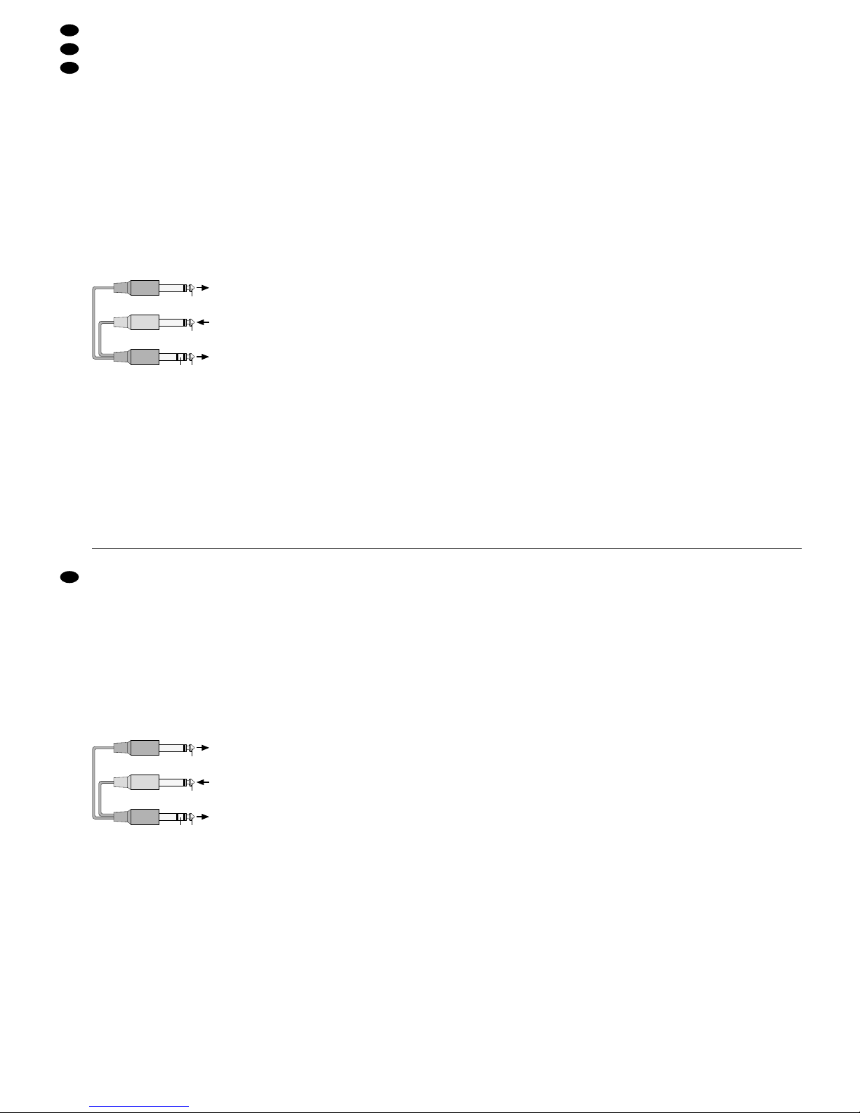
➆
Anschluss des Y-Kabels MCA-202 von MONACOR
Den Stereo-Stecker in die Buchse INS (1) stecken.
Das Ausgangssignal („Send“) liegt an der Spitze des
Stereo-Steckers an, das bearbeitete Eingangssignal
(„Return“) am Ring; am Schaft liegt die gemeinsame
Masse an. Den Mono-Stecker für das Send-Signal
an den Eingang des Gerätes zur Signalbearbeitung
anschließen und den Mono-Stecker für das ReturnSignal an seinen Ausgang.
Hinweis: Bei falsch angeschlossenem, nicht eingeschaltetem oder defektem Effektgerät bleibt der zugehörige Kanal stumm.
5.4 Effektgeräte
Der Ausspielweg AUX 2 ist bei nicht gedrückter Taste
PRE (20) auf post-fader geschaltet und kann dann
als Effektweg genutzt werden. Über diesen Ausspielweg können Signalanteile aus den Eingangskanälen
ausgekoppelt, von einem Effektgerät (z.B. Hallgerät)
bearbeitet und wieder in das Mischpult zurückgeführt und auf die Signalsumme gemischt werden.
Soll zusätzlich der Ausspielweg AUX 1 als Ef fektweg dienen, muss er intern von pre-fader (Grundeinstellung ab Werk) auf post-fader umgestellt werden, siehe Kapitel 4.1.
1) Den Eingang des Effektgerätes an den jeweiligen
Mono-Ausgang AUX SEND (6) anschließen.
2) Den Ausgang des Effektgerätes an den Stereo-
Eingang AUX RETURN (4) anschließen (bei ei-
nem Mono-Effektgerät nur die obere Buchse „L“
verwenden) oder an den Line-Eingang eines
freien Eingangskanals.
5.5 Kopfhörer und Regie-Monitoranlage
Über einen Stereo-Kopfhörer und eine Regie-Monitoranlage lassen sich folgende Signale abhören:
1. das Summensignal
2. das Signal der Subgruppen an den Buchsen
GROUP OUTPUT (46)
3. das Signal eines oder mehrerer Eingangskanäle
4. das Signal der Buchsen AUX RETURN 1 (4)
5. das Signal des Eingangs PLAY (9)
Den Kopfhörer (Impedanz min. 32Ω) an die Buchse
PHONES (10) anschließen, den Eingang der RegieMonitoranlage an die Buchsen CTRL ROOM (7).
Nähere Informationen zu den Abhörfunktionen sind
im Kapitel 6.5 angegeben.
5.6 Aufnahmegerät
Zur Aufnahme der Abmischung das Aufnahmegerät
an die Cinch-Ausgangsbuchsen REC (8) anschließen. Der Aufnahmepegel wird mit den Summenreglern MAIN (41) eingestellt. Während der Aufnahme
darf die Taste 2-TRACK TO MIX (40) nicht gedrückt
sein, sonst kann es zu einer Rückkopplung kommen!
Für die Wiedergabe der Aufzeichnung den Ausgang des Aufnahmegerätes an den Eingang PLAY
(9) anschließen. Um das Wiedergabesignal auf das
Summensignal zu geben, die Taste 2-TRACK TO
MIX (40) drücken; um es über einen Kopfhörer oder
über eine Regie-Monitoranlage abzuhören, die T aste
2-TRACK (29) drücken und alle Tasten PFL/ SOLO
(16) sowie die Taste AUX PFL(25) ausrasten.
5.7 Endverstärker zur Beschallung
Das mit den Summenreglern MAIN (41) ausgesteuerte Summensignal steht im Anschlussfeld MAIN
OUTPUT an den symmetrischen XLR-Buchsen (44)
und an den asymmetrischen 6,3-mm-Klinkenbuchsen (45) zur Verfügung. Hier kann der Endverstärker
für die Saalbeschallung angeschlossen werden.
Über die Ausspielwege AUX, die auf pre-fader
geschaltet sind (siehe Kap. 4.1 und Kap. 6.4), können die Musiker ein separat abgemischtes Musiksignal über Bühnenmonitore zugespielt bekommen.
Die Bühnenmonitore an die entsprechende(n)
Buchse(n) AUX SEND (6) anschließen.
5.8 Signale der Subgruppen
Die Signale der Subgruppen stehen an den Buchsen
GROUPOUTPUT (46) zur Verfügung. Sollen sie z.B.
auf ein weiteres Mischpult oder einen Endverstärker
gegeben werden, dessen Eingang hier anschließen.
5.9 Stromversorgung
Nachdem alle anderen Anschlüsse hergestellt sind,
das beiliegende Netzgerät an die Stromversorgungsbuchse (43) anschließen und den Netzstecker
in eine Steckdose (230V~/50Hz) stecken. Um
Brummeinstrahlungen zu vermeiden, das Netzgerät
möglichst weit vom Mischpult entfernt aufstellen.
Auch wenn das Mischpult ausgeschaltet ist, verbraucht das Netzgerät einen geringen Strom. Darum sollte der Netzstecker aus der Steckdose gezogen werden, wenn das Mischpult längere Zeit nicht
benutzt wird.
Eingang
Gerät zur Klangbearbeitung
Ausgang
Gerät zur Klangbearbeitung
RETURN SEND
RETURN
SEND
rot
schwarz
schwarz
Insert-Buchse
Mischpult
connect the upper jack “L” in each case. Then the
input signal is internally switched to the right and left
channels.
5.3 Inserting units for sound processing
Units for signal processing (like compressors, noise
gates) can be inserted into the mono channels 1 to 4
via the 6.3mm jacks INS (1): The channel signal is
taken off ahead of the channel fader after the equalizer via the insert jack INS, completely runs via the
connected unit and returns via the same jack.
Connect the unit for sound processing via a Y cable,
e.g. MCA-202 from the MONACOR product range.
➆
Connection of the Y cable MCA-202 from MONACOR
Connect the stereo plug to the jack INS (1). The output signal (“Send”) is at the tip of the stereo plug, the
processed input signal (“Return”) at the ring; the
common ground is at the body. Connect the mono
plug for the Send signal to the input of the signal processing unit and the mono plug for the return signal
to its output.
Note: If the effect unit is not correctly connected, not
switched on, or if it is defective, the corresponding
channel remains muted.
5.4 Effect units
The send way AUX 2 is switched to post-fader with
the button PRE (20) not pressed and can then be
used as an effect way. V ia this send way signal parts
can be taken off from the input channels, processed
by an effect unit (e. g. reverb unit) and returned to
the mixer, and added to the master signal.
If the send way AUX 1 is to serve additionally as an
effect way, it must internally be rearranged from prefader (factory setting) to post-fader, see chap. 4.1.
1) Connect the input of the effect unit to the respec-
tive mono output AUX SEND (6).
2) Connect the output of the effect unit to the stereo
input AUX RETURN (4) [in case of a mono effect
unit, only use the upper jack “L”] or to the line
input of an unconnected input channel.
5.5 Headphones and control room monitor
system
Via stereo headphones and a control room monitor
system the following signals can be monitored:
1. the master signal
2. the signal of the subgroups at the jacks GROUP
OUTPUT (46)
3. the signal of one or several input channels
4. the signal of the jacks AUX RETURN 1 (4)
5. the signal of the input PLAY (9)
Connect the headphones (impedance min. 32Ω) to
the jack PHONES (10), the input of the control room
monitor system to the jacks CTRLROOM (7). Detailed information on the monitor functions can be
found in chapter 6.5.
5.6 Recorder
For recording the remixing, connect the recorder to
the phono output jacks REC (8). The recording level
is adjusted with the master faders MAIN (41). During
the recording the button 2-TRACK TO MIX (40) must
not be pressed, otherwise a howlback may occur!
For the replay of the recording, connect the output of
the recorder to the input PLAY(9). T o feed the replay
signal to the master signal, press the button
2-TRACK TO MIX (40); to monitor it via headphones
or via a control room monitor system, press the button 2-TRACK (29) and disengage all buttons PFL/
SOLO (16) and the button AUX PFL(25).
5.7 Power amplifier for PA applications
The master signal controlled with the master faders
MAIN (41) is available at the balanced XLR jacks
(44) and at the unbalanced 6.3mm jacks (45) in the
connection panel MAIN OUTPUT. Here, a power
amplifier for the PA application of the hall can be
connected.
Via the send ways AUX which are switched to
pre-fader (see chapters 4.1 and 6.4), the musicians
can receive a separately mixed music signal via
stage monitors. Connect the stage monitors to the
corresponding jack(s) AUX SEND (6).
5.8 Signals of the subgroups
The signals of the subgroups are available at the
jacks GROUP OUTPUT (46). For feeding them e.g.
to another mixer or to a power amplifier, connect its
input here.
5.9 Power supply
After all other connections have been made,
connect the supplied power supply unit to the power
supply jack (43) and the mains plug to a mains
socket (230 V~ /50 Hz). To avoid hum interference,
set up the power supply unit as far away from the
mixer as possible.
Even if the mixer is switched off, the power supply unit has a low power consumption. Therefore,
the mains plug should be disconnected from the
mains socket if the mixer will not be used for a longer period of time.
input
unit for sound processing
output
unit for sound processing
RETURN SEND
RETURN
SEND
red
black
black
insert jack
mixer
8
GB
D
A
CH

6 Bedienung
Vor dem Einschalten sollten die Summenregler
MAIN (41), die Pegelregler der Ausspielwege AUX
SEND (31), der Lautstärkeregler CTRL ROOM/
PHONES (26) und ggf. die Schieberegler GROUP
(30) auf Minimum gestellt werden, um Einschaltgeräusche zu vermeiden. Dann das Mischpult mit dem
Schalter POWER (42) auf der Geräterückseite einschalten. Die Betriebsanzeige POWER (32) leuchtet. Anschließend die angeschlossenen Geräte einschalten.
6.1 Grundeinstellung der Eingangskanäle
1) Vor dem Einpegeln der Eingangskanäle zuerst:
a) alle Kanalfader (17) und die Fader GROUP
(30) ganz zuziehen sowie alle Gain- (11) und
AUX-Regler (13) auf Minimum drehen
b) folgende Regler in die Mittelstellung drehen:
alle Klangregler (12)
alle Panorama- und Balanceregler (14)
c) folgende Tasten ausrasten:
MUTE/GROUP 1-2 (15) und PFL/SOLO (16) in
allen Eingangskanälen
FX TO AUX 1 (24)
AUX PFL (25)
GROUP 1-2 (28)
2-TRACK (29)
PFL/ SOLO (38) unter der Aussteuerungsan-
zeige
GROUP 1-2 TO MIX (39)
2-TRACK TO MIX (40)
d) in den Mono-Kanälen 1– 4 die Taste MIC/
LINE (18) ausrasten, wenn ein Mikrofon ange-
schlossen ist oder drücken, wenn ein Gerät
mit Line-Ausgang angeschlossen ist
2) Auf den ersten verwendeten Kanal das zugehörige Tonsignal geben und den Kanalfader (17)
auf ca. 0dB aufziehen. Die Summenregler MAIN
(41) so weit aufziehen, dass das Signal über die
angeschlossene PA-Anlage zu hören ist. (Das
Signal lässt sich auch über einen Kopfhörer oder
eine Regie-Monitoranlage kontrollieren – siehe
dazu Kapitel 6.5.)
3) Die Taste PFL/ SOLO (16) des Kanals drücken.
Damit ist die Vorhörfunktion für den Kanal aktiviert:
Die LED (22) neben dieser Taste leuchtet grün
und die LED PFL (37) unter der Aussteuerungsanzeige (35) leuchtet auf. Die Aussteuerungsanzeige zeigt den Pre-fader-Pegel des Kanals an,
wenn die Taste PFL/ SOLO (38) unter der Aussteuerungsanzeige nicht gedrückt ist.
4) Die Eingangsverstärkung mit dem Regler GAIN
(11) anhand der Aussteuerungsanzeige optimal
einstellen: Bei lauten Passagen sollte die Aussteuerungsanzeige Pegelwerte im Bereich von
0dB anzeigen. Falls erforderlich, kann der Regler
auch ganz nach links oder rechts gedreht werden.
5) Den Klang einstellen:
Regler HI für die Höhen (±15dB/12 kHz)
Regler MID für die Mitten (±15dB/2,5kHz)
Regler LO für die Tiefen (±15dB/80 Hz)
Anschließend die Aussteuerung des Kanals überprüfen und ggf. mit dem Regler GAIN korrigieren.
6) Bei einem Mono-Kanal mit der Taste CUT (19)
das Low-Cut-Filter gegen Brummen und Trittschall einschalten, wenn das Tonsignal keine
Frequenzen unter 80Hz enthält.
7) Im Mono-Kanal mit dem Regler PAN (14) das
Signal in der Stereo-Basis platzieren oder im Stereo-Kanal mit dem Regler BAL (14) die Balance
einstellen.
Um diese Einstellung über die Aussteuerungsanzeige und über einen Kopfhörer oder
eine Regie-Monitoranlage zu kontrollieren, die
Taste PFL/SOLO (38) unter der Aussteuerungs-
anzeige drücken. Die LED SOLO (36) leuchtet
und das Kanalsignal wird jetzt nach dem Kanalfader mit entsprechender Panorama- bzw. Balanceeinstellung angezeigt und abgehört.
8) Die Taste PFL/SOLO (16) im Eingangskanal wieder ausrasten. Die LED (22) neben der T aste dient
jetzt als Übersteuerungsanzeige, mit der sich die
Aussteuerung des Kanals grob kontrollieren lässt:
Leuchtet sie kurz rot auf, wird der Kanal gerade
noch nicht übersteuert. Leuchtet sie permanent,
ist der Kanal übersteuert. Dann den Eingangspegel mit dem Regler GAIN (11) reduzieren.
9) Damit bei den Einstellungen für den nächsten
Kanal das Signal des ersten Kanals nicht stört,
die Taste MUTE/GROUP 1-2 (15) des eingepegelten Eingangskanals drücken. Die LED (21)
neben der Taste leuchtet und das Kanalsignal ist
stumm geschaltet, wenn die Fader GROUP (30)
zugezogen sind. Wurde die Taste PFL/SOLO
(38) unter der Aussteuerungsanzeige gedrückt,
diese wieder ausrasten. Die Pegel-, Klang- und
Panorama- bzw. Balanceeinstellung für alle weiteren Eingangskanäle wiederholen.
6.2 Mischen der Tonquellen
1) Die Taste MUTE/ GROUP 1-2 (15) in den Kanälen wieder ausrasten, deren Signale direkt auf
das Summensignal gemischt werden sollen.
2) Die Summenregler MAIN (41) so weit aufziehen,
dass sich das Mischungsverhältnis der angeschlossenen Tonquellen optimal einstellen lässt.
3) Mit den Kanalfadern (17) das gewünschte Lautstärkeverhältnis der Tonquellen einstellen: Die
Tonquellen, die am lautesten zu hören sein sollen, optimal aussteuern (siehe Kap. 6.1) und die
Pegel der übrigen Tonquellen entsprechend reduzieren. Nach Bedarf einzelne Kanäle ein- oder
ausblenden.
Sind zusätzliche Tonquellen an den Eingängen
AUX RETURN (4) angeschlossen, deren Signale
mit den Reglern RTN AUX (23) auf das Summensignal mischen.
Vorsicht!
Stellen Sie die Lautstärke der Audioanlage und die
Kopfhörerlautstärke nie sehr hoch ein. Hohe Lautstärken können auf Dauer das Gehör schädigen!
Das menschliche Ohr gewöhnt sich an große Lautstärken und empfindet sie nach einiger Zeit als nicht
mehr so hoch. Darum eine hohe Lautstärke nach
der Gewöhnung nicht weiter erhöhen.
6 Operation
Prior to switching-on, the master faders MAIN (41),
the level controls of the send ways AUX SEND (31),
the volume control CTRL ROOM/PHONES (26),
and, if required, the sliding controls GROUP (30)
should be set to minimum to avoid switch-on noise.
Then switch on the mixer with the POWER switch
(42) on the rear side of the unit. The operating indication POWER (32) lights up. Then switch on the
connected units.
6.1 Basic setting of the input channels
1) Prior to the level adjustment of the input channels
first:
a) close all channel faders (17) and the faders
GROUP (30) completely and turn all gain controls (11) and AUX controls (13) to minimum
b) turn the following controls to mid-position:
all equalizing controls (12)
all panorama and balance controls (14)
c) disengage the following buttons:
MUTE/GROUP 1-2 (15) and PFL/SOLO (16)
in all input channels
FX TO AUX 1 (24)
AUX PFL (25)
GROUP 1-2 (28)
2-TRACK (29)
PFL/SOLO (38) below the level display
GROUP 1-2 TO MIX (39)
2-TRACK TO MIX (40)
d) disengage the button MIC/ LINE (18) in the
mono channels 1 to 4 if a microphone is
connected or press it if a unit with line output is
connected
2) Feed the corresponding audio signal to the first
channel used and move the channel fader (17)
upwards to approx. 0 dB. Advance the master
faders MAIN (41) until the signal is audible via the
PA system connected. (The signal can also be
monitored via headphones or a control room
monitor system – see chapter 6.5).
3) Press the button PFL/SOLO (16) of the channel.
Thus, the pre-fader listening facility for the channel is activated: The LED (22) next to this button
shows green, and the LED PFL (37) below the
level display (35) lights up. The level display
shows the pre-fader level of the channel if the
button PFL/SOLO (38) below the level display is
not pressed.
4) Adjust the input amplification with the control
GAIN (11) by means of the level display in an optimum way: For high-volume music passages the
level display should display level values in the
0dB range. If required, the control can be turned
fully clockwise or counter-clockwise.
5) Adjust the sound:
control HI for the high range (±15dB/12 kHz)
control MID for the midrange (±15dB/2.5 kHz)
control LO for the bass range (±15dB/80 Hz)
Then check the level adjustment of the channel
and correct it with the control GAIN, if required.
6) In case of a mono channel, switch on the low cut
filter against humming and rumble noise with the
button CUT (19) if the audio signal does not contain any frequencies below 80Hz.
7) In the mono channel place the signal in the
stereo basis with the control PAN (14) or in the
stereo channel adjust the balance with the control BAL (14).
To check this adjustment via the level display
and via headphones or a control room monitor
system, press the button PFL/ SOLO (38) below
the level display. The LED SOLO (36) lights up
and the channel signal is now displayed and monitored after the channel fader with corresponding
panorama and balance adjustment.
8) Disengage the button PFL/SOLO (16) in the
input channel again. The LED (22) next to the
button now serves as an overload LED by which
the level of the channel can coarsely be checked:
If it shortly shows red, the channel is not yet overloaded. If it lights up permanently, the channel is
overloaded. Then reduce the input level with the
control GAIN (11).
9) Press the button MUTE/GROUP 1-2 (15) of the
input channel for which the level has been adjusted so that the signal of the first channel does
not interfere when adjustments are made for the
next channel. The LED (21) next to the button
lights up and the channel signal is muted if the
faders GROUP(30) are closed. If the button PFL/
SOLO (38) below the level display has been
pressed, disengage it again. Repeat the adjustments for level, sound, panorama, and balance
for all further input channels.
6.2 Mixing the audio sources
1) Disengage the button MUTE/GROUP 1-2 (15) in
the channels again, the signals of which are to be
directly added to the master signal.
2) Advance the master faders MAIN (41) so that the
mixing ratio of the audio sources connected can
be adjusted in an optimum way.
3) With the channel faders (17) adjust the desired
volume ratio of the audio sources: Adjust the
audio sources which are to be heard at highest
volume to an optimum level (see chapter 6.1) and
reduce the levels of the remaining audio sources
accordingly. If required, fade in or out individual
channels.
If additional audio sources are connected to
the inputs AUX RETURN (4), add their signals to
the master signal with the controls RTN AUX (23).
4) Fully close or turn off the controls (17, 23) of the
channels which are not used.
5) Press the button MAIN MIX (27) so that the level
display (35) shows the master signal. Disengage
all buttons PFL/SOLO (16) in the input channels
Caution!
Never adjust the audio system and the headphones to a very high volume. Permanent high volumes may damage your hearing! The human ear
will get accustomed to high volumes which do not
seem to be that high any more after some time.
Therefore, do not further increase a high volume
after getting used to it.
9
GB
D
A
CH
4) Die Regler (17, 23) der Kanäle, die nicht benutzt
werden, ganz zuziehen bzw. ganz zudrehen.
5) Damit die Aussteuerungsanzeige (35) das Summensignal anzeigt, die Taste MAIN MIX (27) drücken. Alle Tasten PFL/SOLO (16) in den Eingangskanälen sowie die Taste AUX PFL (25)
ausrasten, so dass unter der Aussteuerungsanzeige weder die LED PFL (37) noch die LED
SOLO (36) leuchtet.
6) Mit den Summenreglern den endgültigen Pegel
des Stereo-Summensignals einstellen, das an
den Ausgängen MAIN OUTPUT (44, 45) und
REC (8) anliegt.
In der Regel wird eine optimale Aussteuerung
erreicht, wenn die Aussteuerungsanzeige bei
durchschnittlich lauten Passagen Werte im 0-dBBereich anzeigt. Ist der Ausgangspegel jedoch
für das nachfolgende Gerät zu hoch oder zu
niedrig, das Summensignal entsprechend niedriger oder höher aussteuern.
6.3 Eingangssignale auf die Subgruppen
mischen
Um mehrere Eingangssignale unabhängig von den
Summenreglern MAIN (41) gemeinsam im Pegel
verändern zu können, lassen sich diese auf die Subgruppen mischen:
auf GROUP 1 immer das linke Kanalsignal und
auf GROUP 2 immer das rechte Kanalsignal.
1) Die Taste MUTE/GROUP 1-2 (15) der Eingangs-
kanäle drücken, deren Signale auf die Subgruppen gemischt werden sollen. Die LED (21) neben
der zugehörigen Taste leuchtet auf.
2) Sollen die Subgruppen auf das Summensignal
gemischt werden, die Taste GROUP 1-2 TO MIX
(39) drücken.
3) Die Fader GROUP (30) für den Pegel der Sub-
gruppen entsprechend auf- und zuziehen.
4) Die Signale der Subgruppen können zur Weiter-
leitung auf z.B. ein anderes Mischpult oder einen
Verstärker an den Buchsen GROUP OUTPUT
(46) abgenommen werden.
6.4 Einstellungen für die Ausspielwege
A Wird ein Ausspielweg als Monitorweg für Büh-
nenmonitore verwendet, sollte er pre-fader ausgelegt sein (Signalabgriffspunkt vor dem Kanalfader). Der Ausspielweg AUX 1 ist ab Werk auf
pre-fader geschaltet. Für den Ausspielweg AUX 2
zum Umschalten auf pre-fader die Tasten PRE
(20) der Eingangskanäle drücken, deren Signale
auf den Monitorweg gemischt werden sollen.
B Wird ein Ausspielweg als Effektweg verwendet,
sollte er post-fader ausgelegt sein (Signalabgriffspunkt nach dem Kanalfader). Der Ausspielweg AUX 2 ist bei nicht gedrückten Tasten
PRE (20) post-fader geschaltet. Der Ausspielweg
AUX 1 kann intern von pre- auf post-fader geändert werden (siehe Kapitel 4.1).
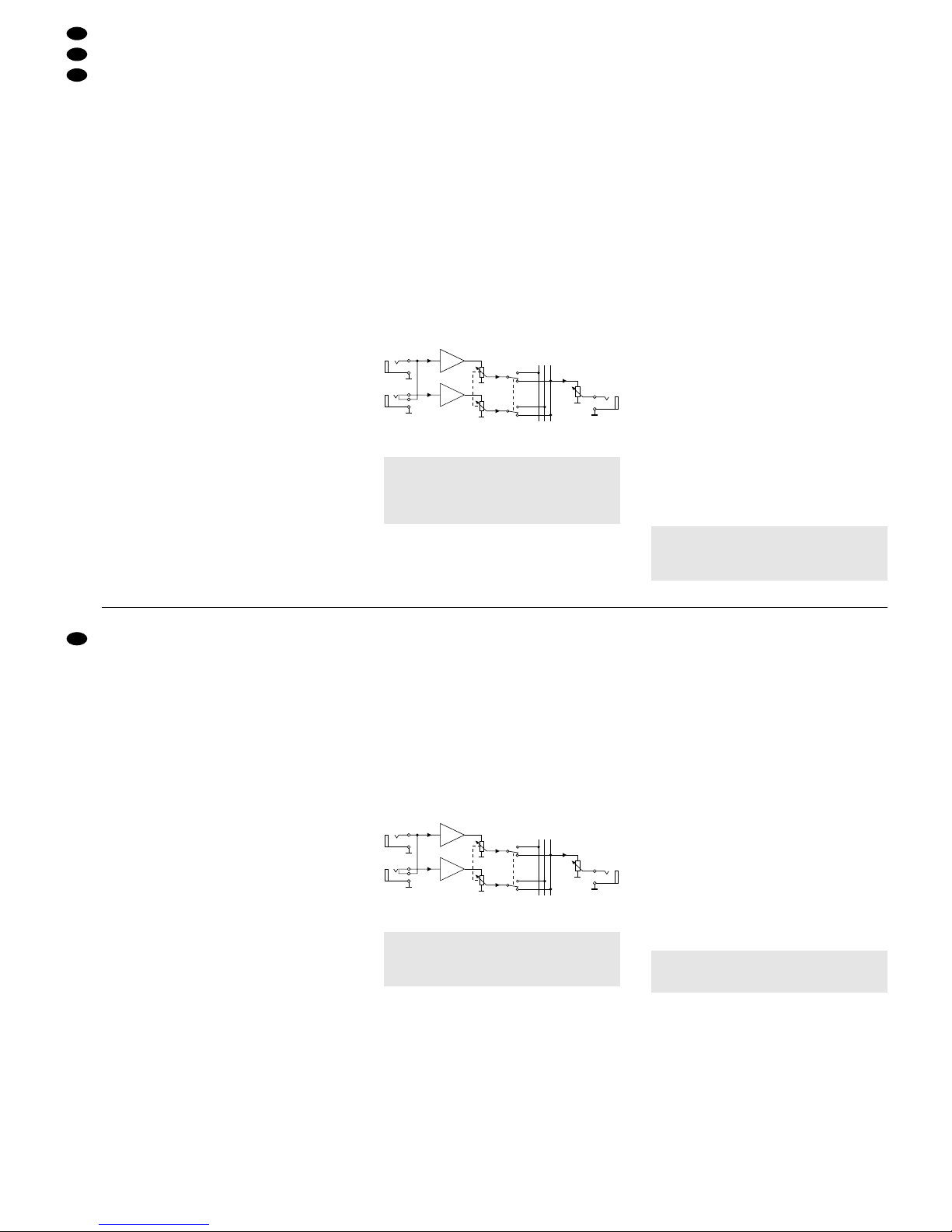
C Wird AUX1 als Monitorweg verwendet und AUX2
als Effektweg, lässt sich das Effektsignal vom
Eingang AUX RETURN 2 anstelle auf das Summensignal auf den Monitorweg AUX 1 schalten.
Dadurch können Effektsignale auf den Monitorweg gegeben werden. Für diese Anwendung die
Taste FX TO AUX 1 (24) drücken.
➇
Signalverlauf bei gedrückter Taste FX TO AUX 1
1) Mit den Reglern AUX (13) – oberer Regler für
AUX 1, unterer für AUX 2 – die Signale der Eingangskanäle wie gewünscht auf die Ausspielwege
mischen. Weil die Ausspielwege monofon ausge-
legt sind, werden die Signale der Stereo-Kanäle
als Mono-Signal auf die Ausspielwege gemischt.
2) Die Signale der Ausspielwege liegen an den zugehörigen Ausgängen AUX SEND (6) an. Den
Ausgangspegel mit dem jeweiligen Pegelregler
AUX SEND (31) einstellen.
3) Wird ein Ausspielweg als Effektweg genutzt,
kann das vom Effektgerät bearbeitete Signal entweder über einen freien Eingangskanal oder
über die Buchsen AUX RETURN (4) wieder in
das Mischpult zurückgeführt werden. Das Signal
mit dem zugehörigen Kanalfader (17) oder dem
zugehörigen Regler RTN AUX (23) auf das Summensignal mischen.
6.5 Abhören der Kanäle
Über einen an der Buchse PHONES (10) angeschlossenen Kopfhörer und über eine an den Buchsen CTRL ROOM (7) angeschlossene Regie-Monitoranlage lassen sich folgende Signale abhören:
A Das Signal des Eingangskanals, dessen PFL/
SOLO-Taste (16) gedrückt ist und
bei gedrückter Taste AUX PFL (25) das Signal
der Buchsen AUX RETURN 1 (4); hierbei darf die
Taste PFL/SOLO (38) unter der Aussteuerungsanzeige nicht gedrückt sein, sonst ist kein Signal
zu hören (zum Abhören des Signals der Buchsen
AUX RETURN 2 siehe Kapitel 4.2)
oder wenn keine dieser Tasten gedrückt ist:
B Das Summensignal der Ausgänge MAIN OUT-
PUT (44, 45), wenn die Taste MAIN MIX (27) gedrückt ist.
C Das Gruppensignal der Ausgänge GROUP OUT-
PUT (46), wenn die Taste GROUP 1-2 (28) gedrückt ist.
D Das Signal des Eingangs PLAY (9), wenn die
Taste 2-TRACK (29) gedrückt ist.
Wichtig! Die Aussteuerungsanzeige (35) zeigt
immer das Signal an, welches über den Kopfhörer und über die Regie-Monitoranlage zu
hören ist.
Wichtig! Für alle anderen Anwendungen als im
Beispiel C angegeben darf die Taste FX TO
AUX1 nicht gedrückt werden. Anderenfalls können Rückkopplungen auftreten oder es wird kein
Effektsignal auf das Summensignal gegeben.
RIGHT
LEFT/
MONO
RTN
AUX 2
FX TO
AUX 1
AUX 1
SEND
L MAIN
BUS
R MAIN
AUX 1
AUX 1
SEND
AUX 2
RETURN
and the button AUX PFL (25) so that neither the
LED PFL (37) nor the LED SOLO (36) below the
level display lights up.
6) With the master faders adjust the final level of the
stereo master signal which is present at the outputs MAIN OUTPUT (44, 45) and REC (8).
Generally, an optimum level is reached if the
level display shows values in the 0dB range for
music passages of average volume. However, if
the output level is too high or too low for the following unit, adjust the level of the master signal
accordingly lower or higher.
6.3 Adding the input signals to the subgroups
To be able to change the level of several input signals together, independent of the master faders
MAIN (41), these input signals can be added to the
subgroups:
to GROUP 1 always the left channel signal and
to GROUP 2 always the right channel signal.
1) Press the button MUTE/GROUP 1-2 (15) of the
input channels, the signals of which are to be
added to the subgroups. The LED (21) next to the
corresponding button lights up.
2) For adding the subgroups to the master signal,
press the button GROUP 1-2 TO MIX (39).
3) Advance or close the faders GROUP (30) for the
level of the subgroups accordingly.
4) The signals of the subgroups can be picked up at
the jacks GROUP OUTPUT (46) for passing
them on e.g. to another mixer or an amplifier.
6.4 Adjustments for the send ways
A If a send way is used as a monitor way for stage
monitors, it should be designed pre-fader (signal
take-off point ahead of the channel fader). The
send way AUX 1 is factory-set to pre-fader. To
switch the send way AUX 2 to pre-fader, press
the buttons PRE (20) of the input channels, the
signals of which are to be added to the monitor
way.
B If a send way is used as an effect way, it should
be designed post-fader (signal take-off point after
the channel fader). The send way AUX 2 is
switched post-fader if the buttons PRE (20) are
not pressed. The send way AUX 1 can internally
be changed from pre-fader to post-fader (see
chapter 4.1).
C If AUX 1 is used as a monitor way and AUX 2 as
an effect way, the effect signal of input AUX RETURN 2 can be switched to the monitor way
AUX 1 instead and not to the master signal. Thus,
effect signals can be fed to the monitor way. Press
the button FX TO AUX 1 (24) for this application.
➇
Signal way with button FX TO AUX 1 pressed
1) Add the signals of the input channels to the send
ways as desired with the controls AUX (13) – upper control for AUX 1, lower control for AUX 2. As
the send ways are designed for mono, the signals of the stereo channels are added to the send
ways as a mono signal.
2) The signals of the send ways are available at the
corresponding outputs AUX SEND (6). Adjust the
output level with the corresponding level control
AUX SEND (31).
3) If a send way is used as an effect way, the signal
processed by the effect unit can either be returned to the mixer via an unconnected input
channel or via the jacks AUX RETURN (4). Add
the signal to the master signal with the corres-
ponding channel fader (17) or the corresponding
control RTN AUX (23).
6.5 Monitoring the channels
The following signals can be monitored via headphones connected to the jack PHONES (10) and via
a control room monitor system connected to the
jacks CTRL ROOM (7):
A The signal of the input channel, of which the but-
ton PFL/SOLO (16) is pressed and,
with the button AUX PFL(25) pressed, the signal
of the jacks AUX RETURN 1 (4); in this case the
button PFL/ SOLO (38) below the level display
must not be pressed, otherwise no signal can be
heard (for monitoring the signal of the jacks AUX
RETURN 2 see chapter 4.2)
or if none of these buttons is pressed:
B The master signal of the outputs MAIN OUTPUT
(44, 45) if the button MAIN MIX (27) is pressed.
C The group signal of the outputs GROUP OUTPUT
(46) if the button GROUP 1-2 (28) is pressed.
D The signal of the input PLAY (9) if the button
2-TRACK (29) is pressed.
1) Select the signals to be monitored with the corresponding buttons. The buttons PFL/ SOLO (16)
of the input channels and the button AUX PFL
(25) take priority over the buttons MAIN MIX (27),
GROUP 1-2 (28), and 2-TRACK (29). For monitoring the master signal, the subgroups, or the
signal of the jacks PLAY (9), all buttons PFL/
SOLO and the button AUX PFLmust therefore be
disengaged so that neither the LED PFL (37) nor
the LED SOLO (36) below the level display lights
up.
2) The signals of the input channels can be monitored pre-fader or post-fader. Select the monitor
function with the button PFL/ SOLO (38) below
the level display:
Important! The level display (35) always shows
the signal which can be heard via the headphones and via the control room monitor system.
Important! The button FX TO AUX 1 must not
be pressed for any other application than stated
in the example C. Otherwise howlbacks may occur or no effect signal is fed to the master signal.
RIGHT
LEFT/
MONO
RTN
AUX 2
FX TO
AUX 1
AUX 1
SEND
L MAIN
BUS
R MAIN
AUX 1
AUX 1
SEND
AUX 2
RETURN
10
GB
D
A
CH

1) Mit den entsprechenden T asten die abzuhörenden
Signale auswählen. Die Tasten PFL/ SOLO (16)
der Eingangskanäle und die Taste AUX PFL(25)
haben Vorrang vor den Tasten MAIN MIX (27),
GROUP 1-2 (28) und 2-TRACK (29). Sollen das
Summensignal, die Subgruppen oder das Signal
der Buchsen PLAY(9) abgehört werden, müssen
darum alle Tasten PFL/SOLO und die Taste AUX
PFL ausgerastet sein, so dass unter der Aussteuerungsanzeige weder die LED PFL(37) noch
die LED SOLO (36) leuchtet.
2) Die Signale der Eingangskanäle lassen sich preoder post-fader abhören. Mit der Taste PFL/
SOLO (38) unter der Aussteuerungsanzeige die
Abhörfunktion wählen:
Taste nicht gedrückt = pre-fader; die LED PFL
(37) leuchtet*. Das Signal ist technisch bedingt nur monofon zu hören.
Taste gedrückt = post-fader; die LED SOLO (36)
leuchtet*. Diese Schalterstellung ist notwendig, wenn z.B. die Panorama- oder Balanceeinstellung überprüft werden soll.
*sobald eine der Tasten PFL/SOLO in einem Ein-
gangskanal oder die Taste AUX PFLgedrückt ist
Das Summensignal und die Subgruppen werden
immer post-fader abgehört, d.h. unabhängig von
der Schalterstellung der Taste PFL/SOLO (38).
3) Die Lautstärke für den Kopfhörer und für die
Regie-Monitoranlage mit dem Regler CTRL
ROOM/ PHONES (26) einstellen.
7 Technische Daten
Eingänge
Eingangsempfindlichkeit/Impedanz
MIC 1– 4, mono: . . . . . . . . 0,1– 20mV/4kΩ,
sym.
LINE1 –4, mono: . . . . . . . 2– 400mV/50kΩ,
sym.
LINE 5/6 –11/12, stereo: . 10– 400mV/20kΩ,
sym.
INSERT 1–4, mono: . . . . . 60mV/12kΩ, asym.
AUX RETURN1 +2, stereo: 110mV/15 kΩ, asym.
PLAY, stereo: . . . . . . . . . . . 250mV/40kΩ, asym.
Klangregelung
Tiefen: . . . . . . . . . . . . . . . . ±15dB/80Hz
Mitten: . . . . . . . . . . . . . . . . ±15dB/2,5 kHz
Höhen: . . . . . . . . . . . . . . . ±15dB/12kHz
Low-Cut-Filter: . . . . . . . . . . . 80Hz
Phantomspeisung: . . . . . . . . +48V
Ausgänge
MAIN OUTPUT, stereo
XLR: . . . . . . . . . . . . . . . . . 1V, sym.
6,3-mm-Klinke: . . . . . . . . . 1 V, asym.
GROUP 1+ 2: . . . . . . . . . . . 1,23V, asym.
REC, stereo: . . . . . . . . . . . . 150mV, asym.
SEND AUX1+ 2, mono: . . . . 1V, asym.
CTRL ROOM, stereo: . . . . . 950mV, asym.
Kopfhörer, stereo: . . . . . . . . ≥ 32 Ω
Frequenzbereich: . . . . . . . . . 20– 30000 Hz
Klirrfaktor: . . . . . . . . . . . . . . < 0,05%
Störabstand: . . . . . . . . . . . . 81dB, bewertet
Aussteuerungsanzeige: . . . . 0dB = 1 V
Allgemeine Daten
Stromversorgung: . . . . . . . . 2 x 19,5V~
über beiliegendes
Netzgerät an
230V~/50Hz/40 VA
zulässige Einsatztemperatur: 0–40°C
Abmessungen
(ohne Montagewinkel): . . . . 340 x 90 x 370mm
Gewicht: . . . . . . . . . . . . . . . . 5kg
Laut Angaben des Herstellers.
Änderungen vorbehalten.
button not pressed = pre-fader, the LED PFL(37)
lights up*. Due to technical reasons, the signal
can only be heard in mono.
button pressed = post-fader, the LED SOLO (36)
lights up*. This switch position is necessary for
checking e. g. the panorama or balance adjustment.
*as soon as one of the buttons PFL/SOLO in an input
channel or the button AUX PFLis pressed
The master signal and the subgroups are always
monitored post-fader, i.e. independent of the
switch position of button PFL/SOLO (38).
3) Adjust the volume for the headphones and for the
control room monitor system with the control
CTRL ROOM/PHONES (26).
7 Specifications
Inputs
Input sensitivity/impedance
MIC 1– 4, mono: . . . . . . . . 0.1– 20mV/4kΩ, bal.
LINE 1– 4, mono: . . . . . . . 2– 400mV/50kΩ,
bal.
LINE 5/6 –11/12, stereo: . 10 –400mV/20 kΩ,
bal.
INSERT 1–4, mono: . . . . . 60mV/12kΩ, unbal.
AUX RETURN 1+ 2,
stereo: . . . . . . . . . . . . . . . . 110mV/15 kΩ, unbal.
PLAY, stereo: . . . . . . . . . . . 250mV/40kΩ, unbal.
Equalizer
bass: . . . . . . . . . . . . . . . . . ±15dB/80Hz
midrange: . . . . . . . . . . . . . ±15dB/2.5 kHz
treble: . . . . . . . . . . . . . . . . ±15dB/12 kHz
Low cut filter: . . . . . . . . . . . . 80Hz
Phantom power: . . . . . . . . . . +48V
Outputs
MAIN OUTPUT, stereo
XLR: . . . . . . . . . . . . . . . . . 1V, bal.
6.3mm jack: . . . . . . . . . . . 1V, unbal.
GROUP 1+ 2: . . . . . . . . . . . 1.23V, unbal.
REC, stereo: . . . . . . . . . . . . 150mV, unbal.
SEND AUX 1+2, mono: . . . 1V, unbal.
CTRL ROOM, stereo: . . . . . 950mV, unbal.
Headphones, stereo: . . . . . . ≥ 32 Ω
Frequency range: . . . . . . . . . 20–30000Hz
THD: . . . . . . . . . . . . . . . . . . < 0.05%
S/N ratio: . . . . . . . . . . . . . . . 81 dB, weighted
Level display: . . . . . . . . . . . . 0dB = 1V
General information
Power supply: . . . . . . . . . . . 2 x 19.5V~ via sup-
plied power supply
unit connected to
230V~/50Hz/40 VA
Ambient temperature: . . . . . 0– 40°C
Dimensions
(w/o mounting brackets): . . . 340 x 90 x 370 mm
Weight: . . . . . . . . . . . . . . . . . 5 kg
According to the manufacturer.
Subject to technical modification.
11
GB
D
A
CH
Diese Bedienungsanleitung ist urheberrechtlich für MONACOR
®
INTERNATIONAL GmbH & Co. KG
geschützt. Eine Reproduktion für eigene kommerzielle Zwecke – auch auszugsweise – ist untersagt.
All rights reserved by MONACOR
®
INTERNATIONAL GmbH & Co. KG. No part of this instruction manual
may be reproduced in any form or by any means for any commercial use.

8 Erklärung der Fachbegriffe
Kursiv gedruckte Wörter sind Stichwörter, die weitererklärt
werden.
asymmetrisch (asym.): Bei asymmetrischer Signalübertra-
gung wird das Signal über eine Signalleitung übertragen. Die
Abschirmung führt das Massepotential.
Gegenteil: symmetrisch.
Ausspielweg (Send): Über einen Ausspielweg lassen sich die
Signale der Eingangskanäle aus dem Mischpult herausführen. Das Signal wird dabei über einen eigenen Regler im
Kanalzug auf den Ausspielweg gemischt. Je nachdem, an
welcher Stelle das Signal abgegriffen wird (pre-fader oder
post-fader), kann der Ausspielweg als Effektweg oder als
Monitorweg genutzt werden. Das Gesamtsignal des Ausspiel-
wegs wird über einen Pegelregler auf den zugehörigen Ausgang gegeben.
CE ( -Zeichen) franz. Communauté Européenne = Europäi-
sche Gemeinschaft: Bestimmte Produkte, die in der EU verkauft werden sollen, müssen das CE-Zeichen tragen. Damit
bestätigt der Hersteller bzw. der Vertreiber, dass das Produkt
die entsprechenden Richtlinien der EU erfüllt (z. B. Richtlinie
für Elektromagnetische Verträglichkeit etc.).
Effektweg: Ein Ausspielweg, der für den Anschluss eines Ef-
fektgerätes (z. B. Hallgerät) genutzt wird. Soll ein Ausspielweg als Effektweg verwendet werden, muss der Abgriffspunkt
des Kanalsignals nach dem Kanalfader (post-fader) liegen.
Elektromagnetische Verträglichkeit (EMV): Die EMV-Richt-
linie 89/ 336 / EWG schreibt vor, wie groß die Störstrahlung
eines Gerätes maximal sein darf und mit welcher Störstrahlung es ohne Probleme belastet werden darf (Störfestigkeit).
Fader engl. to fade in = einblenden: Schieberegler am Misch-
pult, mit dem das Signal eines Kanals ein- und ausgeblendet
sowie der Pegel eingestellt wird.
Gain engl. Verstärkung; hier: Regler im Eingangskanal, mit dem
die Vorverstärkung des Eingangssignals eingestellt wird, um
den Signalpegel an den Arbeitspegel des Mischpults anzupassen. So entstehen bei hohen Eingangspegeln keine Verzerrungen bzw. bei niedrigen Pegeln entsteht kein Rauschen.
Insert engl. to insert = einfügen: Über eine Insert-Buchse lässt
sich ein Gerät zur Klangbearbeitung (z. B. Kompressor) in einen
Signalweg schalten. Das Signal wird über die Buchse herausgeführt, durch das Gerät geschleift und durch dieselbe Buchse
an der gleichen Stelle im Signalweg wieder zurückgeführt.
LED engl. light emitting diode: Elektronisches Bauteil, das elek-
trischen Strom direkt in Licht umwandelt (ohne Erzeugung
von Hitze wie bei einer Glühlampe); leuchtet je nach Material
in verschiedenen Farben oder auch in Weiß.
Line (-Ausgang, -Eingang, -Pegel) engl. Leitung: Um Signale
von einem Gerät zum anderen übertragen zu können, müssen diese einen festgelegten Spannungswert haben, sonst ist
keine optimale Übertragung möglich. Dieser Wert liegt zwischen 0,1 V und 2 V und wird als Line-Pegel bezeichnet. Ein-
und Ausgänge, die für diese Pegel vorgesehen sind, tragen
meistens die Beschriftung LINE.
Monitorweg: Ein Ausspielweg für ein separat abgemischtes
Musiksignal für die Musiker auf der Bühne. Soll ein Ausspielweg als Monitorweg verwendet werden, muss der Abgriffspunkt des Kanalsignals vor dem Kanalfader (pre-fader) liegen.
Niederspannungsrichtlinie (73/23/EWG): Vorschrift für Ge-
räte, die mit Spannungen von 50 – 1500V arbeiten und darum
für den Benutzer entsprechend sicher aufgebaut sein müssen.
Pegel: Spannungswert eines elektrischen Signals bzw. Laut-
stärke eines akustischen Signals.
PFL engl. pre fader listening = (das Signal) vor dem Kanalfader
abhören; siehe auch pre-fader und Vorhören.
Phantomspeisung: Spannungsversorgung für Kondensatormi-
krofone, die an den Kontakten 1 (Masse) und 2, 3 (Pluspol) von
3-poligen XLR-Buchsen anliegt. Das Mikrofonsignal wird nicht
beeinflusst, da nur der Pluspol der Spannungsversorgung auf
den symmetrischen Signalleitungen (Kontakte 2 und 3) liegt.
post-fader lat. post = nach: Ein Signal wird nach dem Kanalfader
abgegriffen, d. h. der Pegel des abgegriffenen Signals wird
vom vorgeschalteten Kanalfader beeinflusst. Ein Post-FaderAusspielweg lässt sich als Effektweg nutzen, bei jeder Verstel-
lung des Kanalfaders ändert sich auch der Pegel des Effektsignals in gleichem Maße.
Gegenteil: pre-fader
pre-fader lat. pre = vor: Ein Signal wird vor dem Kanalfader ab-
gegriffen, d. h. der Pegel des abgegriffenen Signals wird nicht
vom folgenden Kanalfader beeinflusst. Ein Pre-Fader-Aus-
spielweg lässt sich als Monitorweg nutzen, die Bühnenbeschallung für die Musiker kann so unabhängig von der Saalbeschallung erfolgen.
Gegenteil: post-fader
Rack engl. Gestell: In einem Rack für Geräte mit einer genorm-
ten Breite von 482 mm (19") lassen sich z. B. CD-Spieler,
Mischpult, Equalizer, Verstärker zu einer kompletten Audioanlage zusammenstellen.
Return-Eingang engl. to return = zurückkommen: Über diesen
Eingang lässt sich ein Signal, das über einen Ausspielweg
ausgekoppelt und von einem Effektgerät bearbeitet wurde,
wieder in das Mischpult zurückführen
Summenregler, Summensignal: Die Signale der Eingangs-
kanäle werden mit den Kanalfadern zu einem Gesamtsignal,
dem Summensignal, abgemischt; der Pegel dieses Gesamtsignals wird mit den Summenreglern eingestellt.
symmetrisch (sym.): Bei symmetrischer Signalübertragung
wird das Signal über zwei Signalleitungen (+ und -), die von
einer Abschirmung umgeben sind, übertragen. Störeinstrahlungen werden größtenteils unterdrückt, weil sie auf beiden
Signalleitungen gleich auftreten und am Mischpulteingang nur
der Signalunterschied zwischen den Leitungen weiterverstärkt
wird.
Gegenteil: asymmetrisch.
Vorhören: Das Signal eines Eingangskanals wird pre-fader
über einen Kopfhörer abgehört. Auf diese Weise ist es möglich, eine Tonquelle auch bei zugezogenem Kanalfader zu
hören, z. B. um sie zum gewünschten Zeitpunkt einzublenden.
XLR: Geschütztes Warenzeichen für professionelle Steckver-
bindungen. XLR-Stecker und Buchsen sind speziell für sym-
metrische Signalübertragung ausgelegt.
8 Glossary
Words in italics are keywords which are further explained in de-
tail.
AUX send way: Via an AUX send way, the signals of the input
channels can be routed out of the mixer. For this purpose, the
signal is mixed to the AUX send way via an individual control
in the channel. According to the point where the signal is taken (pre-fader or post-fader), the AUX send way can be used
either as an effect way or as a monitor way. The total signal of
the send way is fed via a level control to the corresponding
output.
balanced (bal.): In case of balanced signal transmission, the
signal is transmitted via two signal lines (+ and -) encased in
a screening. Interference will be largely suppressed as it occurs equally on both signal lines and only the signal difference
between the two lines is further amplified at the input of the
mixer.
Opposite: unbalanced
CE ( mark); French: Communauté Européenne = European
Community: Certain products on sale in the EU must have the
CE mark. Thus, the manufacturer or the distributor confirms
that the product meets the corresponding EU requirements
(e. g. directive for electromagnetic compatibility, etc.)
Effect way: An AUX send way used for connecting an effect
unit (e. g. reverberation unit). For using an AUX send way as
an effect way, the channel signal must be taken after the
channel fader (post-fader).
Electromagnetic Compatibility (EMC): The EMC directive
89/ 336 / EEC stipulates the maximum interference of a unit
and the level of interference to which the unit may be subjected without problems (interference resistance).
Fader: Sliding control at the mixer for fading in / fading out the
signal of a channel and for adjusting the level.
Gain; in this context: control in the input channel which adjusts
the preamplification of the input channel for matching the signal level to the operating level of the mixer. Thus, distortions
at high input levels or noise at low levels will be prevented.
Insert: Via an insert jack, a unit for sound processing (e.g.
compressor) can be inserted into a signal way. The signal is
routed out via the jack, fed through the unit and returned via
the same jack at the same point in the signal way.
LED (light emitting diode): Electronic component which directly
converts electric current into light (without generating heat like
an incandescent lamp); according to its material, it shows
different colours or also white.
Level: Voltage value of an electric signal or volume of an
acoustic signal.
Line (line output, line input, line level): For transmitting signals
from one unit to another, these signals must have a fixed voltage value otherwise an optimum transmission is impossible.
This value is between 0.1 V and 2 V and is designated as line
level. Inputs and outputs provided for these levels are mostly
marked LINE.
Low voltage directive (73/ 23 / EEC): Directive for units oper-
ating at voltages from 50 V to 1500 V which must therefore
have a corresponding safe design to protect the user.
Master fader, master signal: The signals of the input channels
are mixed with the channel faders to a total signal, the master
signal; the level of this total signal is adjusted with the master
faders.
Monitor way: An AUX send way for a music signal separately
mixed for the musicians on stage. For using an AUX send way
as a monitor way, the channel signal must be taken ahead of
the channel fader (pre-fader).
Phantom power: Power supply for capacitor microphones
which is applied to the contacts 1 (ground) and 2, 3 (positive
pole) of three-pole XLR jacks. The microphone signal is not
affected as only the positive pole of the power supply is applied to the balanced signal lines (contacts 2 and 3).
Post-fader: A signal is taken after the channel fader, i. e. the
level of the signal taken is influenced by the preceding fader.
A post-fader AUX send way can be used as an effect way;
with each readjustment of the channel fader the level of the
effect signal is changed accordingly.
Opposite: pre-fader
Pre-fader: Asignal is taken ahead of
the channel fader, i. e. the
level of the signal taken is not
influenced by the subsequent
fader. A pre-fader AUX send way can be used as a monitor
way ; thus the PA application on stage can be made independently of the PA application in halls.
Opposite: post-fader
Pre-fader listening (PFL): Pre-fader monitoring of the signal of
an input channel via headphones. Thus, it is possible to listen
to an audio source despite a closed channel fader, e. g. for in-
serting it at the desired time.
Rack: In a rack for units with a standardized width of 482 mm
(19"), e. g. CD players, mixers, equalizers, amplifiers can be
compiled to set up complete audio systems.
Return input: Via this input, a signal taken via an AUX send
way and processed by an effect unit can be returned to the
mixer.
unbalanced (unbal.): In case of unbalanced signal transmis-
sion, the signal is transmitted via a single signal line. The
screening carries the ground potential.
Opposite: balanced
XLR: Registered trade mark for professional connectors. XLR
plugs and jacks are specially designed for balanced signal
transmission.
12
GB
D
A
CH

Ouvrez le présent livret page 3 de manière à visualiser les éléments et branchements.
Table des matières
1 Eléments et branchements . . . . . . . . . . . . . . . . . . 13
1.1 Panneau de branchement sur la face avant . . . . . . . 13
1.2 Canaux d’entrée . . . . . . . . . . . . . . . . . . . . . . . . . . . . 14
1.3 Panneau de branchement en sortie . . . . . . . . . . . . . 14
1.4 Face arrière . . . . . . . . . . . . . . . . . . . . . . . . . . . . . . . . 14
2 Conseils de sécurité et d’utilisation . . . . . . . . . . . 15
3 Possibilités d’utilisation . . . . . . . . . . . . . . . . . . . . . 15
4 Modification de la voie AUX 1 et de la fonction
écoute AUX-RETURN . . . . . . . . . . . . . . . . . . . . . . . 16
4.1 Modification de AUX 1 de pré-fader sur post-fader . . 16
4.2 Modification de la fonction écoute de
AUX RETURN 1 sur AUX RETURN 2 . . . . . . . . . . . . 16
5 Branchements . . . . . . . . . . . . . . . . . . . . . . . . . . . . . 16
5.1 Microphones . . . . . . . . . . . . . . . . . . . . . . . . . . . . . . . 16
5.2 Appareils avec niveau de sortie ligne . . . . . . . . . . . . 16
5.3 Insertion d’appareils pour travailler le son . . . . . . . . .17
5.4 Appareils à effets . . . . . . . . . . . . . . . . . . . . . . . . . . . . 17
5.5 Casque et système moniteur en régie . . . . . . . . . . . 17
5.6 Enregistreur . . . . . . . . . . . . . . . . . . . . . . . . . . . . . . . .17
5.7 Amplificateur pour la sonorisation . . . . . . . . . . . . . . .17
5.8 Signaux des sous-groupes . . . . . . . . . . . . . . . . . . . . 17
5.9 Alimentation . . . . . . . . . . . . . . . . . . . . . . . . . . . . . . . 17
6 Utilisation . . . . . . . . . . . . . . . . . . . . . . . . . . . . . . . . . 18
6.1 Réglage de base des canaux d’entrée . . . . . . . . . . . 18
6.2 Mixage des sources audio . . . . . . . . . . . . . . . . . . . . 18
6.3 Mixage des signaux d’entrée dans les sous-groupes . 19
6.4 Réglages pour les voies . . . . . . . . . . . . . . . . . . . . . . 19
6.5 Ecoute des canaux . . . . . . . . . . . . . . . . . . . . . . . . . . 19
7 Caractéristiques techniques . . . . . . . . . . . . . . . . . 20
8 Glossaire . . . . . . . . . . . . . . . . . . . . . . . . . . . . . . . . . 21
1 Eléments et branchements
1.1 Panneau de branchement sur la face avant
(schéma 1)
1 Prises INS des canaux mono 1 à 4 pour insérer
des appareils pour traiter le signal (noise gate,
compresseur etc), voir chap. 5.3 ; configuration :
pointe : Send (sortie)
anneau : Return (entrée)
corps : masse
2 Prises d’entrée (prises combinées XLR/jack
6,35 femelles, symétriques) des canaux mono 1
à 4 pour brancher des microphones ou des appareils mono à sortie ligne (p.ex. instruments de
musique) ; le branchement de chaque source de
signal est possible au choix par prise XLR mâle
ou prise jack 6,35 mâle.
3 Entrées (jack 6,35, symétriques) des canaux 5/6
et 7/8 pour brancher des appareils stéréo avec
sortie ligne*
4 Entrées AUX RETURN 1 et 2 (prises jack 6,35,
asymétriques) :
peuvent être utilisées comme entrées Return ou
comme entrées ligne stéréo supplémentaires
pour brancher d’autres sources de signal ligne*
5 Entrées (jack 6,35, symétriques) des canaux 9/10
et 11/12 pour brancher des appareils stéréo avec
sortie ligne*
6 Sorties AUX SEND (jack 6,35, asymétriques)
des deux voies AUX 1 et AUX 2 (13)
7 Sortie CTRL ROOM (“control room”, prises jack
6,35, asymétriques) pour brancher un système
moniteur en régie ; via cette sortie et la sortie
casque (10), les signaux suivants peuvent être
écoutés :
1. Le signal du canal dont la touche PFL /SOLO
(16) est enfoncée et si la touche AUX PFL(25)
est enfoncée, le signal des prises AUX RETURN 1 (4).
Ou si aucune de ces touches n’est enfoncée :
2. Le signal master des sorties MAIN OUTPUT
(44, 45) si la touche MAIN MIX (27) est enfoncée.
3. Le signal de groupe des sorties GROUP OUTPUT (46) si la touche GROUP 1-2 (28) est enfoncée.
4. Le signal de l’entrée PLAY (9) si la touche
2-TRACK (29) est enfoncée.
Réglez le niveau de sortie avec le réglage CTRL
ROOM/PHONES (26).
8 Sortie enregistrement REC (RCA, asymétrique)
pour brancher à l’entrée d’un enregistreur ; le niveau d’enregistrement dépend des réglages master MAIN (41).
9 Entrée lecture PLAY (RCA, asymétrique) pour
brancher à la sortie lecture de l’enregistreur relié
aux prises REC (8) ou d’un autre appareil avec
sortie ligne (par exemple lecteur CD)
Pour écouter le signal des prises PLAY via un
casque ou un système moniteur en régie, enfoncez la touche 2-TRACK (29) ; pour commuter le
signal sur le signal master, enfoncez la touche
2-TRACK TO MIX (40).
10 Prise jack 6,35 femelle PHONES pour un casque
stéréo (impédance minimale 32Ω).
Pour sélectionner le signal à écouter, voir position 7. Réglez le volume avec le réglage CTRL
ROOM/PHONES (26).
* Conseil : pour un appareil mono, utilisez uniquement la
prise supérieure “L(
MONO)”. Le signal est commuté alors en
interne sur le canal droit et le canal gauche.
Attention !Si l’alimentation fantôme est allumée
[la LED rouge de contrôle “PHANTOM POWER
+48V” (34) brille], les contacts XLR de ces prises
sont alimentés par une tension fantôme 48V. En
aucun cas, il ne faut brancher de microphones
avec sortie asymétrique à ces contacts XLR, les
microphones peuvent être endommagés.
Il est cependant possible de déconnecter
l’alimentation fantôme séparément pour chaque entrée XLR avec les interrupteurs DIP
PHANTOM POWER (47).
Vi preghiamo di aprire completamente la pagina 3.
Così vedrete sempre gli elementi di comando e i
collegamenti descritti.
Indice
1 Elementi di comando e collegamenti . . . . . . . . . . 13
1.1 Collegamenti sul pannello frontale . . . . . . . . . . . . . . 13
1.2 Canali d’ingresso . . . . . . . . . . . . . . . . . . . . . . . . . . . . 14
1.3 Settore delle uscite . . . . . . . . . . . . . . . . . . . . . . . . . . 14
1.4 Pannello posteriore . . . . . . . . . . . . . . . . . . . . . . . . . . 15
2 Avvertenze di sicurezza . . . . . . . . . . . . . . . . . . . . . 15
3 Possibilità d’impiego . . . . . . . . . . . . . . . . . . . . . . . 16
4 Modifica della via d’uscita AUX 1 e della
funzione di ascolto AUX-RETURN . . . . . . . . . . . . . 16
4.1 Modificare AUX 1 da pre-fader a post-fader . . . . . . . 16
4.2 Modificare la funzione di ascolto
da AUX RETURN 1 a AUX RETURN 2 . . . . . . . . . . . 16
5 Collegamento degli apparecchi . . . . . . . . . . . . . . . 16
5.1 Microfoni . . . . . . . . . . . . . . . . . . . . . . . . . . . . . . . . . . 16
5.2 Apparecchi con uscita LINE . . . . . . . . . . . . . . . . . . . 16
5.3 Inserire apparecchi per l’elaborazione del suono . . . 17
5.4 Unità per effetti . . . . . . . . . . . . . . . . . . . . . . . . . . . . . 17
5.5 Cuffie e impianto di monitoraggio . . . . . . . . . . . . . . . 17
5.6 Registratori . . . . . . . . . . . . . . . . . . . . . . . . . . . . . . . . 17
5.7 Amplificatore finale per sonorizzazione . . . . . . . . . . . 17
5.8 Segnali dei sottogruppi . . . . . . . . . . . . . . . . . . . . . . . 17
5.9 Alimentazione . . . . . . . . . . . . . . . . . . . . . . . . . . . . . . 17
6 Funzionamento . . . . . . . . . . . . . . . . . . . . . . . . . . . . 18
6.1 Impostazione base dei canali d’ingresso . . . . . . . . . 18
6.2 Miscelare le sorgenti audio . . . . . . . . . . . . . . . . . . . . 18
6.3 Miscelare i segnali d’ingresso sui sottogruppi . . . . . . 19
6.4 Impostazione per le vie d’uscita . . . . . . . . . . . . . . . . 19
6.5 Ascolto dei canali . . . . . . . . . . . . . . . . . . . . . . . . . . . 19
7 Dati tecnici . . . . . . . . . . . . . . . . . . . . . . . . . . . . . . . . 20
8 Spiegazione dei termini tecnici . . . . . . . . . . . . . . . 21
1 Elementi di comando e collegamenti
1.1 Collegamenti sul pannello frontale (fig. 1)
1 Prese INS dei canali mono 1 a 4 per l’inserimen-
to di apparecchi per l’elaborazione dei segnali
(noise gate, compressore ecc.), vedi cap. 5.3;
Contatti dei connettori:
punta = Send (uscita)
anello = Return (ingresso)
corpo = Massa
2 Prese d’ingresso (prese combo XLR/jack
6,3mm, simm.) dei canali mono 1 a 4 per il collegamento di microfoni o apparecchi mono con
uscita Line (p.es. strumenti musicali); il collegamento di ogni sorgente è possibile, a scelta, tramite connettore XLR o jack 6,3mm
3 Ingressi (jack 6,3 mm, simm.) dei canali 5/ 6 e
7/8 per il collegamento di apparecchi stereo con
uscita Line *
4 Ingressi AUX RETURN 1 e 2 (jack 6,3mm,
asimm.):
possono essere usati come ingressi Return o
come ingressi supplementari stereo Line per il
collegamento di ulteriori sorgenti Line*
5 Ingressi (jack 6,3 mm, simm.) dei canali 9 /10 e
11/ 12 per il collegamento di apparecchi stereo
con uscita Line*
6 Uscite AUX SEND (jack 6,3 mm, asimm.) delle
due vie d’uscita AUX 1 e AUX 2 (13)
7 Uscita CTRL ROOM (“control room”, jack
6,3 mm, asimm.) per il collegamento di un impianto di monitoraggio per la regia; tramite quest’uscita e l’uscita cuffia (10) si possono ascoltare i seguenti segnali:
1. il segnale del canale, il cui tasto PFL /SOLO
(16) è premuto, e con il tasto AUX PFL (25)
premuto si può ascoltare il segnale delle prese
AUX RETURN 1 (4)
oppure, se nessuno di questi tasti è premuto:
2. il segnale delle somme delle uscite MAIN
OUTPUT (44, 45), se è premuto il tasto MAIN
MIX (27);
3. il segnale di gruppo delle uscite GROUP OUTPUT (46), se è premuto il tasto GROUP 1-2
(28);
4. il segnale dell’ingresso PLAY (9), se è premuto il tasto 2-TRACK (29).
Impostare il livello dell’uscita con il regolatore
CTRL ROOM/PHONES (26).
8 Uscita di registrazione REC (RCA, asimm.) per il
collegamento con l’ingresso di un registratore;
il livello di registrazione dipende dai regolatori
delle somme MAIN (41)
9 Ingresso di riproduzione PLAY (RCA, asimm.)
per il collegamento con l’uscita di riproduzione
del registratore collegato con le prese REC (8) o
di un altro apparecchio con uscita Line (p.es. lettore CD)
Per ascoltare il segnale delle prese PLAYtramite
una cuffia o l’impianto di monitoraggio, premere
il tasto 2-TRACK (29); per portare questo segnale sul segnale delle somme, premere il tasto
2-TRACK TO MIX (40).
10 Presa jack 6,3 mm PHONES per una cuffia ste-
reo (impedenza min. 32Ω)
Per determinare il relativo segnale vedi posizione 7. Impostare il volume con il regolatore
CTRL ROOM/PHONES (26).
*N.B.: Nel caso di un apparecchio mono usare solo la presa
superiore “L (MONO)”. Il segnale viene portato internamente
sul canale destro e sinistro.
Attenzione! Con alimentazione phantom attivata [LED rosso di controllo “PHANTOM POWER +48V” (34) è acceso], i contatti XLR di queste prese sono con alimentazione phantom di
48V. In questo caso, ai contatti XLR non devono
essere collegati dei microfoni con uscita asimmetrica, perché potrebbero subire dei danni.
Tuttavia, l’alimentazione phantom può essere disattivata per ogni ingresso XLR separatamente per mezzo dei dip-switch PHANTOM POWER (47).
13
I
F
B
CH

1.2 Canaux d’entrée (schéma 3 et 4)
11 Potentiomètres de réglage Gain pour l’amplifica-
tion d’entrée
12 Egaliseur 3 voies :
HI pour les aigus (±15dB/12kHz)
MID pour les médiums (±15dB/2,5 kHz)
LO pour les graves (±15dB/80Hz)
13 Potentiomètres de réglage AUX pour mixer les
signaux des canaux 1 à 12 respectivement sur la
voie AUX 1 (pré-fader ; réglage supérieur) et sur
la voie AUX 2 [pré/post-fader, commutable avec
la touche (20) ; réglage inférieur]
Conseil : pour la voie AUX 1, le point de repiqua-
ge du signal peut être modifié, séparément pour chaque canal, en interne sur
post-fader (voir chapitre 4.1).
14 Pour les canaux mono 1 à 4 :
potentiomètres de réglage de panoramique
PAN pour placer le signal mono dans la base
stéréo ;
si la touche MUTE/ GROUP 1-2 (15) est enfoncée, le réglage sert également pour attribuer le signal de canal sur les sous-groupes
Pour les canaux stéréo 5/6 à 11/12 :
potentiomètres de réglage de balance BAL
pour régler le rapport de niveau entre le canal
gauche et le canal droit
15 Touches MUTE/GROUP 1-2
Touche non enfoncée, la LED (21) ne brille pas :
le canal est mixé sur le signal master des sorties MAIN OUTPUT (44, 45) et REC (8).
Touche enfoncée : la LED brille :
le canal est mixé sur les sous-groupes des
sorties GROUP OUTPUT (46).
Si les faders GROUP (30) sont poussés, cette
touche peut être utilisée également pour couper le signal du canal.
16 Touches PFL/SOLO : pour contrôler le canal
sélectionné via un casque relié à la prise PHONES (10) et via un système moniteur en régie relié aux prises CTRL ROOM (7) :
soit pour une préécoute (PFL = Pre Fader Li-
stening) si la touche PFL/ SOLO (38) dans le
champ de connexion en sortie n’est pas enfoncée – la LED (22) dans le canal d’entrée brille en
vert et la LED verte PFL (37) sous le VU-mètre
est allumée.
soit pour contrôler le réglage complet des canaux après le fader du canal (SOLO) si la touche
PFL/ SOLO (38) dans le champ de connexion en
sortie est enfoncée – la LED (22) dans le canal
d’entrée brille en vert et la LED rouge SOLO (36)
sous le VU-mètre est allumée.
Le VU-mètre (35) indique toujours le signal correspondant du canal si la touche PFL/SOLO (16)
est enfoncée.
17 Faders de canaux
18 Touches MIC/LINE pour les canaux mono 1 à 4 :
Touche enfoncée : pour brancher un appa-
reil avec sortie ligne
Touche non enfoncée : pour brancher un micro-
phone
19 Touches CUT pour les canaux mono 1 à 4 pour
allumer/éteindre le filtre Low Cut ; élimine les fréquences non souhaitées sous 80Hz comme les
ronflements ou bruits de pas
20 Commutateur pour la voie AUX 2
Touche enfoncée : le signal du canal est dé-
couplé avant le fader
(pré-fader)
Touche non enfoncée : le signal du canal est dé-
couplé après le fader
(post-fader)
21 LEDs rouges de contrôle : brillent si la touche
MUTE/ GROUP 1-2 (5) correspondante est enfoncée
22 LEDs de contrôle : servent soit comme témoins
d’écrêtage soit comme témoins PFL :
1. Si la fonction PFL pour le canal n’est pas activée [touche PFL/SOLO (16) non enfoncée],
un allumage bref et rouge de la LED indique
que le signal du canal a atteint son niveau maximal pour lequel il n’est pas encore en sur-
charge ; si la LED est tout le temps rouge, le
canal est en surcharge.
2. Lorsque la fonction PFL est activée pour le canal (touche PFL/SOLO est enfoncée), la LED
brille tout le temps en vert.
1.3 Panneau de branchement en sortie
(schéma 5)
23 Potentiomètres de réglage RTN AUX pour mixer
les signaux présents aux entrées AUX RETURN
(4) sur le signal master
24 Touche FX TO AUX 1 pour diriger le signal des
prises d’entrée AUX RETURN 2 (4)
Touche enfoncée : le signal est dirigé sur la
voie AUX 1 (chapitre 6.4)
Touche non enfoncée : le signal est mixé au si-
gnal master
25 Touche AUX PFL pour une écoute du signal des
prises AUX RETURN 1 (4) via un casque relié à
la prise PHONES (10) et via un système moniteur en régie relié aux prises CTRL ROOM (7).
Conseil : Si AUX RETURN 1 ne doit pas être
écouté, mais AUX RETURN 2, le cavalier JP9 peut être repositionné en interne (voir chapitre 4.2).
26 Potentiomètre de réglage de volume CTRL
ROOM/PHONES pour un casque relié à la prise
PHONES (10) et pour un système moniteur en
régie relié aux prises CTRL ROOM (7)
27 Touche MAIN MIX : commute le signal master*
pour une écoute sur les sorties CTRL ROOM (7)
et PHONES (10)
28 Touche GROUP 1-2 : commute le signal* des
sous-groupes pour une écoute sur les sorties
CTRL ROOM (7) et PHONES (10)
29 Touche 2-TRACK : commute le signal* des pri-
ses PLAY (9) pour une écoute sur les sorties
CTRL ROOM (7) et PHONES (10)
* Conseil : Pour pouvoir écouter ce signal, ni une des tou-
ches PFL/SOLO (16) ni la touche AUX PFL(25) ne doivent
être enfoncées.
1.2 Canali d’ingresso (figg. 3 e 4)
11 Regolatori GAIN per l’amplificazione dell’ingresso
12 Regolazione toni a 3 frequenze diverse:
HI per gli alti (±15dB/12 kHz)
MID per i medi (±15dB/2,5kHz)
LO per i bassi (±15dB/80 Hz)
13 Regolatori AUX per miscelare i segnali dei canali
1 a 12 ognuno sulla via d’uscita AUX 1 [pre-fader; regolatore superiore] e sulla via d’uscita
AUX 2 [pre-/post-fader commutabile con il tasto
(20); regolatore inferiore]
N.B.: Per la via d’uscita AUX 1, il punto di pre-
lievo del segnale può essere modificato internamente, separatamente per ogni canale, a post-fader (vedi capitolo 4.1).
14 Per i canali mono 1 a 4:
Regolatore panoramico PAN per posizionare il
segnale mono nella base stereo;
se è premuto il tasto MUTE/GROUP 1-2 (15),
il regolatore serve anche per attribuire il segnale del canale ai sottogruppi
per i canali stereo 5/6 a 11/12:
Regolatore del bilanciamento BAL per impostare il rapporto di livello fra i canali destro e sinistro
15 Tasto MUTE/GROUP 1-2
Tasto non premuto, non si accende il LED (21):
Il canale viene miscelato sul segnale delle
somme delle uscite MAIN OUTPUT (44, 45) e
REC (8).
Tasto premuto, si accende il LED:
Il canale viene miscelato sui sottogruppi delle
uscite GROUP OUTPUT (46).
Se i fader GROUP (30) sono chiusi, questo
tasto può essere usato anche per rendere
muto il segnale del canale.
16 Tasti PFL/ SOLO per controllare il canale scelto
per mezzo di una cuffia collegata con la presa
PHONES (10) e tramite un impianto di monitoraggio collegato con le prese CTRL ROOM (7):
o per il preascolto (PFL = Pre Fader Listening),
se il tasto PFL/SOLO (38) nel settore delle uscite
non è premuto – il LED (22) nel canale d’ingresso è verde, e il LED verde PFL(37) sotto l’indicazione del livello si accende
o per controllare tutta l’impostazione del canale a
valle del fader del canale (SOLO), se il tasto
PFL/ SOLO (38) nel settore delle uscite è premuto – il LED (22) nel canale d’ingresso è verde
e il LED rosso SOLO (36) sotto l’indicazione del
livello si accende
L’indicazione del livello (35), se è premuto il tasto
PFL/SOLO (16), indica sempre il relativo segnale del canale.
17 Fader del canale
18 Tasti MIC/LINE per i canali mono 1 a 4:
Tasto premuto: per il collegamento di un appa-
recchio con uscita Line
non premuto: per il collegamento di un micro-
fono
19 Tasti CUTper i canali mono 1 a 4 per dis/attivare
il filtro low-cut: sopprime le frequenze indesiderate inferiori a 80Hz, come p. es. ronzìo, passi
20 Commutatori per la via d’uscita AUX 2
Tasto premuto: il segnale del canale viene dis-
accoppiato a monte del fader
(pre-fader)
non premuto: il segnale del canale viene dis-
accoppiato a valle del fader
(post-fader)
21 LED rossi di controllo: si accendono se il relativo
tasto MUTE/GROUP 1-2 (15) è premuto
22 LED di controllo: servono per indicare il sovrapi-
lotaggio oppure la condizione PFL
1. Se la funzione PFL non è stata attivata per il
canale [Tasto PFL/ SOLO (16) non premuto],
una breve accensione del LED di colore rosso
indica che il segnale del canale ha raggiunto il
suo livello massimo, appena sotto il livello di
sovrapilotaggio; se il LED rimane acceso di color rosso significa che il canale è sovrapilotato.
2. Se la funzione PFL è stata attivata per il canale (Tasto PFL/ SOLO premuto), il LED rimane acceso di color verde.
1.3 Settore delle uscite (fig. 5)
23 Regolatori di livello RTN AUX per miscelare i
segnali presenti agli ingressi AUX RETURN (4)
sul segnale delle somme
24 Tasto FX TO AUX 1 per inoltrare il segnale delle
prese d’ingresso AUX RETURN 2 (4)
Tasto premuto: il segnale viene inoltrato sulla
via d’uscita AUX 1 (cap. 6.4)
non premuto: il segnale viene miscelato nel
segnale delle somme
25 Tasto AUX PFL per ascoltare il segnale delle
prese AUX RETURN 1 (4) tramite una cuffia collegata con la presa PHONES (10) oppure tramite
un impianto di monitoraggio collegato con le
prese CTRL ROOM (7)
N.B.: Se non si vuole ascoltare AUX RETURN 1
bensì AUX RETURN 2, si può spostare internamente il jumper JP9 (vedi cap. 4.2).
26 Regolatore del volume CTRL ROOM /PHONES
per una cuffia collegata con la presa PHONES
(10) e per un impianto di monitoraggio collegato
con le prese CTRL ROOM (7)
27 Tasto MAIN MIX: porta il segnale delle somme*
sulle uscite CTRLROOM (7) e PHONES (10) per
ascoltarlo
28 Tasto GROUP 1-2: porta il segnale* dei sotto-
gruppi sulle uscite CTRL ROOM (7) e PHONES
(10) per ascoltarlo
29 Tasto 2-TRACK: porta il segnale* delle prese
PLAY (9) sulle uscite CTRL ROOM (7) e PHONES (10) per ascoltarlo
30 Fader per il livello del fader dei sottogruppi 1 e 2
alle prese GROUP OUTPUT (46)
31 Regolatori del livello AUX SEND per i segnali
delle vie d’uscita AUX 1 e AUX 2 presenti alla
prese AUX SEND (6)
* N. B.: Per poter ascoltare questi segnali non deve essere
premuto nessuno dei tasti PFL/ SOLO (16) e neanche il
tasto AUX PFL (25).
14
I
F
B
CH

30 Faders pour le niveau de signal des sous-grou-
pes 1 et 2 aux prises GROUP OUTPUT (46)
31 Potentiomètres de réglage de niveau AUX SEND
pour les signaux présents aux prises AUX SEND
(6) des voies AUX 1 et AUX 2
32 Témoin de fonctionnement
33 Interrupteur pour allumer l’alimentation fantôme
48V pour les entrées XLR (2) ; indispensable si
des microphones à condensateur ou électret
fonctionnant avec une alimentation fantôme 48V
sont branchés. Pour déconnecter l’alimentation
fantôme de chaque canal, voir position 47.
34 Témoin de l’alimentation fantôme, brille lorsque
l’alimentation fantôme 48V est allumée
35 VU-mètre: indique les signaux sélectionnés pour
une écoute via un casque ou un système moniteur en régie – voir également position 7.
Pour afficher le signal master, désenclenchez
toutes les touches PFL/SOLO (16) dans les canaux d’entrée et la touche AUX PFL(25) ; enfoncez la touche MAIN MIX (27).
36 LED de contrôle SOLO: brille si une des touches
PFL/SOLO (16) ou la touche AUX PFL (25) est
enfoncée et si la fonction moniteur SOLO est
sélectionnée en enfonçant la touche PFL/SOLO
(38).
37 LED de contrôle PFL : brille si une des touches
PFL/SOLO (16) ou la touche AUX PFL (25) est
enfoncée et si la fonction moniteur PFLest sélectionnée par la touche PFL/ SOLO (38) désenclenchée.
38 Touche PFL/ SOLO pour commuter la fonction
moniteur pour les canaux d’entrée 1 à 12 :
T ouche enfoncée : fonction moniteur SOLO :
les signaux des canaux
dont la touche PFL/
SOLO (16) est enfoncée
peuvent être écoutés
après le fader du canal
(post-fader)
Touche non enfoncée : fonction moniteur PFL :
les signaux des canaux
dont la touche PFL/
SOLO (16) est enfoncée,
peuvent être écoutés
avant le fader du canal
(pré-fader)
39 Touche GROUP 1-2 TO MIX, commute les si-
gnaux des sous-groupes sur le signal master
40 Touche 2-TRACK TO MIX, commute le signal
des prises PLAY(9) sur le signal master
41 Faders MAIN pour le signal master aux prises
MAIN OUTPUT (44, 45) et REC (8)
1.4 Face arrière (schéma 6)
42 Interrupteur marche/arrêt
43 Prise d’alimentation pour brancher le bloc sec-
teur livré
44 Sortie pour le signal master via les prises XLR
(symétriques)
45 Sortie pour le signal master via les prises jack
6,35 (asymétriques)
46 Sortie pour les signaux des sous-groupes via les
prises jack 6,35 (asymétriques)
47 Interrupteurs DIP pour déconnecter séparément
l’alimentation fantôme pour les entrées XLR (2)
des canaux 1 à 4
2 Conseils de sécurité et d’utilisation
La table de mixage et le bloc secteur livré répondent
à la directive européenne 89/336 /CEE sur la compatibilité électromagnétique ; le bloc secteur répond
en plus à la directive portant sur les appareils à
basse tension 73/23/CEE.
Respectez scrupuleusement les points suivants :
●
La table de mixage et le bloc secteur ne sont
conçus que pour une utilisation en intérieur. Protégez-les des éclaboussures, de tout type de projections d’eau, d’une humidité élevée et de la chaleur (température ambiante admissible 0– 40°C).
●
En aucun cas, vous ne devez poser pas d’objet
contenant du liquide ou un verre sur les appareils.
●
La chaleur dégagée par la table de mixage doit
être évacuée par la circulation d’air. En aucun cas,
les ouïes de ventilation du boîtier ne doivent être
obturées.
●
Ne faites pas fonctionner la table de mixage et
débranchez le bloc secteur immédiatement dans
les cas suivants :
1. la table de mixage, le bloc secteur ou le cordon
secteur du bloc secteur présentent des dommages visibles.
2. après une chute ou accident similaire, vous
avez un doute sur l’état de l’appareil.
3. des dysfonctionnements apparaissent.
Dans tous les cas, les dommages doivent être
réparés par un technicien spécialisé.
●
Tout cordon secteur du bloc secteur endommagé
ne doit être remplacé que par le fabricant ou un
atelier habilité.
●
Ne débranchez jamais l’appareil en tirant sur le
cordon secteur ; retirez toujours le cordon secteur
en tirant la fiche.
Attention ! Le bloc secteur est alimenté par une tension dangereuse en 230V~. Ne touchez jamais l’intérieur de l’appareil car, en cas de mauvaise manipulation, vous pouvez subir une décharge électrique. En outre, l’ouverture de la table de mixage ou
du bloc secteur rend tout droit à la garantie caduque.
Attention : pour éviter les bruits de commutation, n’activez l’interrupteur que si la table de
mixage est éteinte ou que si toutes les sorties
de la table de mixage sont fermées. Respectez
également le conseil de la position 2 !
32 Spia di funzionamento
33 Interruttore per attivare l’alimentazione phantom
48V per gli ingressi XLR (2); indispensabile se si
collegano microfoni a condensatore o a elettrete
che funzionano con alimentazione phantom
48 V; per disattivare l’alimentazione phantom di
singoli canali vedi posizione 47
34 Spia dell’alimentazione phantom, si accende con
l’alimentazione phantom 48V attivata
35 Spia di sovrapilotaggio: indica i segnali scelti per
l’ascolto tramite una cuffia o un impianto di monitoraggio – vedi anche posizione 7
Per indicare il segnale delle somme, sbloccare
tutti i tasti PFL/SOLO (16) nei canali d’ingresso
nonché il tasto AUX PFL (25), e premere il tasto
MAIN MIX (27).
36 LED di controllo SOLO: è acceso se uno dei tasti
PFL/ SOLO (16) o il tasto AUX PFL (25) è premuto e se con il tasto PFL/SOLO (38) premuto è
stata scelta la funzione monitor SOLO
37 LED di controllo PFL: si accende se uno dei tasti
PFL/ SOLO (16) o il tasto AUX PFL (25) e premuto e se con il tasto PFL/SOLO (38) sbloccato
è stata scelta la funzione monitor PFL
38 Tasto PFL/SOLO per cambiare la funzione moni-
tor per i canali d’ingresso 1 a 12
Tasto premuto funzione monitor SOLO: i se-
gnali dei canali, i cui tasti PFL/
SOLO (16) sono premuti, possono essere ascoltati a valle del
fader del canale (post-fader).
non premuto funzione monitor PFL: i segnali
dei canali, i cui tasti PFL/SOLO
(16) sono premuti, possono essere ascoltati a monte del fader
del canale (pre-fader).
39 Tasto GROUP 1-2 TO MIX, porta i segnali dei
sottogruppi sul segnale delle somme
40 Tasto 2-TRACK TO MIX, porta il segnale delle
prese PLAY(9) sul segnale delle somme
41 Fader MAIN per il segnale delle somme alle
prese MAIN OUTPUT (44, 45) e REC (8)
1.4 Pannello posteriore (fig. 6)
42 Interruttore on/off
43 Presa di alimentazione per il collegamento del-
l’alimentatore in dotazione
44 Uscita per segnale delle somme tramite prese
XLR (simm.)
45 Uscita per segnale delle somme tramite prese
jack 6,3mm (asimm.)
46 Uscita per i segnali dei sottogruppi tramite prese
jack 6,3mm (asimm.)
47 Dip-switch per disattivare l’alimentazione phan-
tom separatamente per gli ingressi XLR (2) dei
canali 1 a 4
2 Avvertenze di sicurezza
Il mixer e l’alimentatore in dotazione sono conformi
alla direttiva CE 89/336/CEE sulla compatibilità elettromagnetica. L’alimentatore è in più conforme alla direttiva 73/23/CEE per apparecchi a bassa tensione.
Durante l’uso si devono osservare assolutamente i
seguenti punti:
●
Usare il mixer e l’alimentatore solo all’interno di locali. Proteggerli dall’acqua gocciolante e dagli
spruzzi d’acqua, da alta umidità dell’aria e dal calore
(temperatura d’impiego ammessa fra 0 e 40°C).
●
Non depositare sugli apparecchi dei contenitori
riempiti di liquidi, p.es. bicchieri.
●
Dev’essere garantita la libera circolazione dell’aria
per dissipare il calore che viene prodotto all’interno dell’apparecchio. Non coprire in nessun
modo le fessure d’aerazione.
●
Non mettere in funzione il mixer e staccare subito
l’alimentatore dalla rete se:
1. il mixer, l’alimentatore o il cavo rete presentano
dei danni visibili;
2. dopo una caduta o dopo eventi simili sussiste il
sospetto di un difetto;
3. l’apparecchio non funziona correttamente.
Per la riparazione rivolgersi sempre ad un’officina
competente.
●
Il cavo rete, se danneggiato, deve essere sostituito solo dal costruttore o da un laboratorio autorizzato.
●
Staccare il cavo rete afferrando la spina, senza tirare il cavo.
●
Per la pulizia usare solo un panno morbido,
asciutto; non impiegare in nessun caso prodotti
chimici o acqua.
Attenzione!
L’alimentatore funziona con tensione di rete di
230V~. Non intervenire mai al suo interno; la manipolazione scorretta può provocare delle scariche
pericolose. Se l’alimentatore o il mixer vengono
aperti, cessa ogni diritto di garanzia.
Attenzione! Per escludere rumori di commutazione, azionare l’interruttore solo con il mixer
spento oppure se tutte le uscite del mixer sono
chiuse. Si prega di notare anche la nota della
posizione 2!
15
I
F
B
CH

●
Pour le nettoyage, utilisez un chiffon sec et doux,
en aucun cas de produits chimiques ou d’eau.
●
Nous déclinons toute responsabilité en cas de
dommages corporels ou matériels résultants si la
table de mixage ou le bloc secteur est utilisé dans
un but autre que celui pour lequel il a été conçu,
s’ils ne sont pas correctement branchés, utilisés
ou réparés par une personne habilitée ; en outre,
la garantie deviendrait caduque.
3 Possibilités d’utilisation
La table de mixage MMX-1202 est spécialement
conçue pour une utilisation sur scène et pour les
musiciens. Il est possible de mixer sur un canal master stéréo, deux sous-groupes et deux voies auxiliaires, les 4 canaux d’entrée mono et les 4 canaux
d’entrée stéréo. Les canaux d’entrée sont dotés de
diverses possibilités de réglage, par exemple :
– potentiomètres de réglage de gain, dans les ca-
naux mono, en plus un commutateur de niveau
MIC/LINE
– prise Insert dans les canaux mono
– filtre anti-bruit de pas dans les canaux mono
– pour les entrées micro, alimentation fantôme
commutable séparément
– égaliseur 3 voies
– 2 réglages de découplage : AUX 1 pré-fader, mo-
difiable en interne sur post-fader, AUX 2 commu-
table pré/post-fader
– réglages de panoramique et de balance
– touche PFL/SOLO pour préécoute via un casque
ou un système moniteur en régie
– LED pour affichage Peak et PFL
La table de mixage peut être posée librement ou installée dans un rack pour appareils avec une largeur
de 482mm (19") ; pour une installation en rack, vissez les étriers de montage livrés sur les côtés
(schéma 2).
4 Modification de la voie AUX 1 et de la
fonction écoute AUX-RETURN
1) Eteignez la table de mixage.
2) Retirez la plaque sur la face inférieure de l’appareil (6 vis).
3) Effectuez les modifications souhaitées selon les
indications du chapitre 4.1 et 4.2.
4) Revissez la plaque.
4.1 Modification de AUX 1 de pré-fader sur
post-fader
La voie AUX1 est réglée en usine comme voie moniteur : les signaux d’entrée sont découplés avant le
fader du canal (17) (pré-fader). Si elle doit servir de
voie d’effet, déplacez les cavaliers JP1– JP8 en fonction de l’inscription sur la face inférieure de l’appareil, sur post-fader.
4.2 Modification de la fonction écoute de AUX
RETURN 1 sur AUX RETURN 2
En enfonçant la touche AUX PFL(25), il est possible
d’écouter le signal des prises AUX RETURN 1 (4)
via un casque relié à la prise PHONES (10) et via un
système moniteur en régie relié aux prises CTRL
ROOM (7). Si à la place le signal des prises AUX
RETURN 2 doit être écouté, déplacez le cavalier
JP9 selon l’inscription sur la face inférieure de l’appareil.
5 Branchements
Avant de brancher des appareils ou modifier des
branchements existants, éteignez la table de
mixage et tous les appareils audio reliés ou fermez
toutes les sorties de la table de mixage.
5.1 Microphones
Reliez des microphones aux prises d’entrée symétriques MIC/LINE (2), soit via une fiche XLR mâle soit
via une fiche jack 6,35 mâle. Reliez toujours via une
fiche XLR mâle des microphones à alimentation
fantôme car l’alimentation fantôme ne peut être
commutée que pour les contacts XLR.
Si des microphones à alimentation fantôme et des
microphones avec sortie asymétrique doivent fonctionner simultanément, déconnectez tout d’abord
avec les interrupteurs DIP (47) sur la face arrière de
l’appareil, l’alimentation fantôme pour les canaux
auxquels des microphones avec sortie asymétriques
sont reliés (interrupteurs DIP sur la position OFF).
Ensuite, table de mixage éteinte, allumez avec l’interrupteur PHANTOM POWER +48V (33) l’alimentation
fantôme. Une fois la table de mixage allumée, la LED
rouge (34) sous l’interrupteur sert de contrôle et brille.
5.2 Appareils avec niveau de sortie ligne
Reliez les appareils stéréo avec niveau de sortie ligne aux prises jack 6,35 (3 et 5) des canaux 5/6 à
11/ 12. Comme entrées ligne stéréo supplémentaires, on peut également utiliser les prises jack AUX
RETURN (4) si elles ne sont pas nécessaires pour
insérer un appareil à effets.
Attention !
●
Déconnectez l’alimentation fantôme pour des
microphones à sortie asymétrique, ils peuvent
être endommagés.
●
Allumez ou éteignez l’alimentation fantôme uniquement si la table de mixage est éteinte ou si
toutes les sorties de la table de mixage sont fermées sinon des bruits forts de commutation surviennent.
Lorsque les appareils sont définitivement retirés du marché, vous devez les
déposer dans une usine de recyclage de
proximité pour contribuer à leur élimination non polluante.
●
Nel caso d’uso improprio, di collegamenti sbagliati, d’impiego scorretto o di riparazione scorretta
del mixer o dell’alimentatore, non si assume nessuna responsabilità per eventuali danni consequenziali a persone o a cose e non si assume nessuna garanzia per gli apparecchi.
3 Possibilità d’impiego
Il mixer MMX-1202 è previsto specialmente per musicisti e per spettacoli. I quattro canali mono e i
quattro canali stereo possono essere miscelati su un
canale stereo delle somme, su due sottogruppi e su
due vie d’uscita. I canali sono equipaggiati con diverse possibilità di regolazione, p.es.:
– regolatori gain, per i canali mono in più un com-
mutatore del livello MIC/LINE
– presa Insert per i canali mono
– filtro low-cut per i canali mono
– alimentazione phantom attivabile separatamente
per gli ingressi microfoni
– regolazione toni a 3 frequenze diverse
– due regolatori di disaccoppiamento: AUX 1 pre-
fader, internamente commutabile a post-fader;
AUX 2 commutabile pre-/post-fader
– regolatore panoramico o bilanciamento
– tasto PFL/SOLO per il preascolto tramite cuffia o
impianto di monitoraggio
– LED per visualizzazione picchi e PFL
Il mixer può essere collocato liberamente oppure
può essere inserito in un rack per apparecchi della
larghezza di 482mm (19"). Per il montaggio nel rack
si devono avvitare sui lati gli angoli di montaggio in
dotazione (fig. 2).
4 Modifica della via d’uscita AUX 1 e
della funzione di ascolto AUX-RETURN
1) Spegnere il mixer.
2) Svitare la piastra di copertura sul lato inferiore
(6 viti).
3) Eseguire le modifiche come da capitolo 4.1 e 4.2.
4) Riavvitare la piastra di copertura.
4.1 Modificare AUX 1 da pre-fader a post-fader
Dalla fabbrica, la via d’uscita AUX 1 è impostata
come via di monitoraggio: i segnali d’ingresso vengono disaccoppiati a monte del fader del canale (17)
(pre-fader). Se deve servire come vie per effetti,
spostare i jumper JP1 – JP8 su post-fader, come indicato sul lato inferiore dell’apparecchio.
4.2 Modificare la funzione di ascolto da AUX
RETURN 1 a AUX RETURN 2
Premendo il tasto AUX PFL (25), il segnale delle
prese AUX RETURN 1 (4) può essere ascoltato tramite una cuffia collegata con la presa PHONES (10)
oppure tramite un impianto di monitoraggio collegato con le prese CTRL ROOM (7). Se invece si
vuole ascoltare il segnale delle prese AUX RETURN
2, spostare il jumper JP9 come indicato sul lato inferiore dell’apparecchio.
5 Collegamento degli apparecchi
Prima di collegare altri apparecchi o di modificare
connessioni esistenti occorre spegnere il mixer e
tutti gli altri apparecchi audio oppure chiudere tutte
le uscite del mixer.
5.1 Microfoni
Collegare i microfoni con le prese simmetriche d’ingresso MIC/LINE (2). Lo si può fare con un connettore XLR oppure con un jack 6,3mm. I microfoni con
alimentazione phantom devono sempre essere collegati tramite un connettore XLR, in quanto l’alimentazione phantom può essere attivata solo tramite i
contatti XLR.
Se si devono usare contemporaneamente microfoni con alimentazione phantom e microfoni con
uscita asimmetrica, occorre dapprima disattivare
l’alimentazione phantom per i canali con microfoni
con uscita asimmetrica [mettere i dip-switch (47) sul
retro dell’apparecchio su OFF]. Solo allora, con il
mixer spento, accendere l’alimentazione phantom
48V con l’interruttore PHANTOM POWER +48 V
(33). Dopo l’accensione del mixer si accende, come
controllo, il LED rosso (34) sotto l’interruttore.
5.2 Apparecchi con uscita Line
Collegare gli apparecchi stereo con livello d’uscita
Line con le prese jack 6,3 mm (3 e 5) dei canali 5/6
a 11/12. Anche le prese jack AUX RETURN (4) possono essere utilizzate come ingressi supplementari
stereo Line, se non sono impiegate per l’inserimento
di unità per effetti.
Le sorgenti di segnali con uscita mono Line si collegano alle prese MIC/LINE (2) dei canali 1 a 4. Se
Attenzione!
●
Per microfoni con uscita asimmetrica disattivare
l’alimentazione phantom per non danneggiarli.
●
Attivare e disattivare l’alimentazione phantom
solo con il mixer spento oppure con tutte le uscite del mixer chiuse per escludere rumori di commutazione.
Se si desidera eliminare gli apparecchi
definitivamente, consegnarli per lo smaltimento ad un’istituzione locale per il riciclaggio.
16
I
F
B
CH

Reliez les sources de signal avec sortie ligne
mono aux prises MIC/LINE (2) des canaux 1 à 4. Si
des appareils mono sont branchés aux canaux
stéréo 5/6 à 11/12 ou aux entrées stéréo AUX RETURN, connectez uniquement la prise supérieure
“L”. Le signal d’entrée est commuté ensuite en interne respectivement sur le canal droit et le canal
gauche.
5.3 Insertion d’appareils pour travailler le son
Via les prises jack 6,35 INS (1), il est possible d’insérer des appareils pour travailler le son (p. ex. compresseurs, noise gate) dans les canaux mono 1 à 4 :
le signal du canal est découplé avant le fader du canal après l’égaliseur via la prise Insert INS , il circule
complètement via l’appareil relié, et est redirigé via
la même prise. Reliez l’appareil pour le traitement du
son, via un cordon en Y, par exemple MCA-202 de la
gamme MONACOR.
➆
Branchement du cordon en Y, MCA-202 de MONACOR
Placez la fiche stéréo dans la prise INS (1) ; le signal
de sortie (“Send”) est présent à la pointe de la fiche
stéréo, le signal d’entrée traité (“Return”) est à l’anneau : au corps se trouve la masse commune. Reliez la fiche mono pour le signal Send à l’entrée de
l’appareil pour traiter le son et la fiche mono pour le
signal Return à sa sortie.
Conseil : si l’appareil à effet n’est pas correctement
branché, pas allumé ou défectueux, le canal correspondant reste muet.
5.4 Appareils à effets
La voie AUX 2 est configurée post-fader si la touche
PRE (20) n’est pas enfoncée et peut être ainsi utilisée comme voie d’effet. Via cette sortie des parties
de signal peuvent être découplées des canaux d’entrée, travaillées par un appareil à effets (par exemple appareil à réverbération) puis redirigées vers la
table de mixage et mixées sur le signal master.
Si la voie AUX 1 doit en plus être utilisée comme
voie d’effet, elle doit être réglée en interne de pré-fader (réglage de base à la sortie d’usine) sur post-fader – voir chapitre 4.1.
1) Reliez l’entrée de l’appareil à effets à la sortie
concernée mono AUX SEND (6).
2) Reliez la sortie de l’appareil à effets à l’entrée sté-
réo AUX RETURN (4) [pour un appareil à effets
mono, utilisez uniquement la prise supérieure “L”]
ou à l’entrée ligne d’un canal d’entrée libre.
5.5 Casque et système moniteur en régie
Les signaux suivants peuvent être écoutés via un
casque stéréo ou un système moniteur en régie :
1. Le signal master
2. Le signal des sous-groupes aux prises GROUP
OUTPUT (46)
3. Le signaux d’un ou plusieurs canaux d’effets
4. Le signal des prises AUX RETURN 1 (4)
5. Le signal de l’entrée PLAY (9)
Reliez le casque (impédance minimale 32 Ω) à la
prise PHONES (10), l’entrée du système moniteur
en régie aux prises CTRLROOM (7). Reportez-vous
au chapitre 6.5 pour de plus amples informations.
5.6 Enregistreur
Pour enregistrer le mixage, reliez l’enregistreur aux
prises de sortie RCA REC (8). Le niveau d’enregistrement est réglé via les réglages master MAIN (41).
Pendant l’enregistrement, il ne faut pas enfoncer la
touche 2-TRACK TO MIX (40), sinon on peut avoir
un effet larsen !
Pour la restitution de l’enregistrement, reliez la
sortie de l’enregistreur à l’entrée PLAY(9). Pour appliquer le signal de lecture au signal master, enfoncez la touche 2-TRACK TO MIX (40) ; pour l’écouter
via un casque ou un système moniteur en régie, enfoncez la touche 2-TRACK (29) et désenclenchez
toutes les touches PFL/SOLO (16) ainsi que la touche AUX PFL (25).
5.7 Amplificateur pour la sonorisation
Le signal master géré avec les faders master MAIN
(41) est disponible dans le panneau de branchement MAIN OUTPUT aux prises XLR symétriques
(44) et aux prises jack 6,35 asymétriques (45). On
peut relier ici l’amplificateur final pour la sonorisation
de salle.
Via les voies AUX, branchées sur pré-fader (voir
chap. 4.1 et chapitre 6.4), les musiciens peuvent recevoir un signal mixé séparément via les moniteurs
de scène. Reliez les moniteurs de scène à la prise
(aux prises) AUX SEND (6) correspondante(s).
5.8 Signaux des sous-groupes
Les signaux des sous-groupes sont disponibles aux
prises GROUP OUTPUT (46). S’ils doivent être appliqués par exemple vers une autre table de mixage
ou un amplificateur final, reliez son entrée ici.
5.9 Alimentation
Une fois tous les branchements effectués, reliez le
bloc secteur livré à la prise d’alimentation (43) puis
branchez le cordon secteur à une prise secteur
230 V~/50 Hz. Pour éviter tout ronflements, positionnez le bloc secteur le plus loin possible de la table de mixage.
Même lorsque la table de mixage est éteinte, le
bloc secteur a une faible consommation. Il est recommandé de débrancher la fiche du cordon de la
prise secteur en cas de non utilisation prolongée de
la table de mixage.
Entrée
appareil pour
traitement du son
Sortie
appareil pour
traitement du son
RETURN SEND
RETURN
SEND
rouge
noir
noir
Prise insert
table de mixage
si collegano apparecchi mono ai canali stereo 5/6 a
11/12 oppure agli ingressi stereo AUX RETURN usare solo la presa superiore “L”. Il segnale d’ingresso
sarà portato internamente sui canali di destra e di sinistra.
5.3 Inserire apparecchi per l’elaborazione del
suono
Per mezzo delle prese jack 6,3 mm INS (1) si possono inserire nei canali mono 1 a 4 apparecchi per
elaborare i segnali (come p.es. compressori, noisegate): il segnale del canale viene disaccoppiato a
monte del fader dopo la regolazione toni attraverso
la presa insert INS, passa attraverso l’apparecchio
collegato e viene riportata attraverso la stessa
presa. Collegare tale apparecchio mediante un cavo
ad Y, p.es. MCA-202 del programma MONACOR.
➆
Collegamento del cavo ad Y MCA-202 di MONACOR
Inserire la spina stereo nella presa INS (1). Il segnale d’uscita (“Send”) è presente alla punta del
connettore stereo, il segnale d’ingresso elaborato
(“Return”) all’anello; la massa comune è sul corpo.
Collegare il connettore mono per il segnale Send
con l’ingresso dell’apparecchio per l’elaborazione
del suono e il connettore mono per il segnale Return
con l’uscita dell’apparecchio.
N.B.: Nel caso di un’unità per effetti collegata non
correttamente, non accesa o difettosa, il relativo canale rimane muto.
5.4 Unità per effetti
La via d’uscita AUX 2 è impostata post-fader se il
tasto PRE (20) non è premuto, e pertanto può essere utilizzata come via per effetti. Tramite questa
via d’uscita è possibile disaccoppiare parte dei segnali dei canali d’ingresso, elaborarli in un’unità per
effetti (p.es. di riverbero) e riportarli nel mixer e miscelarli sulla somma del segnali.
Se si vuole utilizzare la via d’uscita AUX 1 anche
come via per effetti, occorre cambiare la via internamente da pre-fader (impostazione base dalla fabbrica) a post-fader – vedi cap. 4.1.
1) Collegare l’ingresso dell’unità per effetti con la re-
lativa uscita mono AUX SEND (6).
2) Collegare l’uscita dell’unità per effetti con l’ingres-
so stereo AUX RETURN (4) [nel caso di un’unità
mono per effetti utilizzare solo la presa superiore
“L”], oppure con l’ingresso Line di un canale li-
bero d’ingresso.
5.5 Cuffia e impianto di monitoraggio
Tramite una cuffia stereo e un impianto di monitoraggio si possono ascoltare i seguenti segnali:
1. il segnale delle somme
2. il segnale dei sottogruppi alle prese GROUP
OUTPUT (46)
3. il segnale di uno o più canali d’ingresso
4. il segnale delle prese AUX RETURN 1 (4)
5. il segnale dell’ingresso PLAY (9)
Collegare la cuffia (impedenza min. 32 Ω) con la
presa PHONES (10), l’ingresso dell’impianto di monitoraggio con le prese CTRLROOM (7). Ulteriori informazioni sulle funzioni di ascolto si trovano nel capitolo 6.5.
5.6 Registratore
Per registrare i segnali miscelati, collegare il registratore con le prese d’uscita RCA REC (8). Il livello
di registrazione viene impostato con i regolatori delle
somme MAIN (41). Durante la registrazione, il tasto
2-TRACK TO MIX (40) non deve essere premuto,
altrimenti si può creare un feedback!
Per la riproduzione della registrazione collegare
l’uscita del registratore con l’ingresso PLAY (9).
Per portare il segnale di riproduzione sul segnale
delle somme premere il tasto 2-TRACK TO MIX
(40); per ascoltarlo tramite cuffia o un impianto di
monitoraggio, premere il tasto 2-TRACK (29) e
sbloccare tutti i tasti PFL/SOLO (16) nonché il tasto
AUX PFL (25).
5.7 Amplificatore finale per la sonorizzazione
Il segnale delle somme regolato con i regolatori delle
somme MAIN (41) è disponibile nel settore dei collegamenti MAIN OUTPUT alla prese XLR simmetriche
(44) e alle prese asimmetriche jack 6,3mm (45). Qui
si può collegare l’amplificatore finale per la sonorizzazione della sala.
Tramite le vie d’uscita AUX, messe su pre-fader
(vedi cap. 4.1 e cap. 6.4), ai musicisti può arrivare un
segnale di musica miscelato separatamente per
mezzo di appositi monitor. Collegare i monitor con la
relativa presa le relative prese AUX SEND (6).
5.8 Segnali dei sottogruppi
I segnali dei sottogruppi sono disponibili alle prese
GROUP OUTPUT (46). Se devono esser portati per
esempio su un altro mixer o su un amplificatore, si
collega qui l’ingresso di detti apparecchi.
5.9 Alimentazione
Dopo aver effettuato tutti i collegamenti collegare
l’alimentatore in dotazione con la presa di alimentazione (43) e inserire la spina in una presa di
rete (230 V~/50 Hz). Per evitare interferenze conviene tener l’alimentatore il più lontano possibile dal
mixer.
Anche con il mixer spento, l’alimentatore consuma un po’di corrente. Perciò conviene staccare la
spina dalla presa di rete se il mixer non viene usato
per un certo periodo.
Ingresso
apparecchio per
l’elaborazione del suono
Uscita
apparecchio per
l’elaborazione del suono
RETURN SEND
RETURN
SEND
rosso
nero
nero
Presa Insert
Mixer
17
I
F
B
CH

6 Utilisation
Avant de mettre la table sous tension, les faders
master MAIN (41), les réglages de niveau des voies
AUX SEND (31), le réglage de volume CTRLROOM/
PHONES (26) et si besoin les potentiomètres
GROUP (30) devraient être mis sur le minimum pour
éviter tout bruit fort à l’allumage. Allumez ensuite la
table de mixage avec l’interrupteur POWER (42) sur
la face arrière. Le témoin de fonctionnement POWER
(32) brille. Ensuite allumez les appareils reliés.
6.1 Réglage de base des canaux d’entrée
1) Avant d’effectuer les réglages des canaux d’entrée, vous devez tout d’abord :
a) Pousser entièrement tous les faders (17) et
les faders GROUP (30), et mettre sur le minimum tous les réglages Gain (11) et AUX (13).
b) Mettre les réglages suivants sur la position
médiane
tous les réglages de l’égaliseur (12)
tous les réglages de panoramique et de ba-
lance (14)
c) Déverrouiller les touches suivantes :
MUTE/ GROUP 1-2 (15) et PFL/ SOLO (16)
dans tous les canaux d’entrée :
FX TO AUX 1 (24)
AUX PFL (25)
GROUP 1-2 (28)
2-TRACK (29)
PFL/SOLO (38) sous le VU-mètre
GROUP 1-2 TO MIX (39)
2-TRACK TO MIX (40)
d) dans les canaux mono 1– 4, désenclenchez la
touche MIC/LINE (18) si un micro est relié ou
enfoncez-la si un appareil avec sortie ligne est
relié.
2) Sur le premier canal utilisé, appliquez le signal audio correspondant et poussez le fader du canal
(17) sur 0dB environ. Poussez les réglages master MAIN (41) jusqu’à ce que le signal soit audible
via l’installation de sonorisation reliée. (Le signal
peut également être contrôlé via un casque ou un
système moniteur en régie, voir chap. 6.5).
3) Enfoncez la touche PFL/SOLO (16) du canal. La
fonction préécoute pour le canal est ainsi activée : la LED (22) à côté de la touche brille en
vert et la LED PFL (37) sous le VU-mètre (35)
brille. Le VU-mètre indique le niveau pré-fader du
canal si la touche PFL/ SOLO (38) sous le VUmètre n’est pas enfoncée.
4) Réglez de manière optimale l’amplification d’entrée avec le réglage GAIN (11) selon les indications du VU-mètre : pour des passages élevés, le
VU-mètre devrait afficher des valeurs dans la
plage 0dB. Si besoin, vous pouvez tourner le potentiomètre entièrement à droite ou à gauche.
5) Réglez la tonalité :
potentiomètre HI pour les aigus
(±15dB/12kHz)
potentiomètre MID pour les médiums
(±15dB/2,5kHz)
potentiomètre LO pour les graves
(±15dB/80Hz)
Ensuite, vérifiez le contrôle du canal, si besoin,
corrigez-le avec le réglage GAIN.
6) Pour un canal mono, allumez le filtre Low Cut
avec la touche CUT(19) contre les ronflements et
bruits de pas si le signal audio ne contient pas de
fréquences sous 80 Hz.
7) Dans le canal mono, avec le réglage PAN (14), placez le signal dans la base stéréo ou dans le canal
stéréo avec le réglage BAL(14), réglez la balance.
Pour contrôler ce réglage via le VU-mètre et
via un casque ou un système moniteur en régie,
enfoncez la touche PFL/SOLO (38) sous le VUmètre. La LED SOLO (36) brille et le signal du ca-
nal est affiché et écouté maintenant après le fader du canal avec le réglage de panoramique et
de balance correspondant.
8) Désenclenchez à nouveau la touche PFL/SOLO
(16) dans le canal d’entrée. La LED (22) à côté
de la touche sert maintenant de témoin d’écrêtage avec lequel on peut contrôler grossièrement
le réglage du canal : si elle brille brièvement en
rouge, le canal n’est pas encore en surcharge. Si
elle brille en permanence en rouge, le canal est
en surcharge. Réduisez alors le niveau d’entrée
avec le réglage GAIN (11).
9) Pour que lors des réglages pour le canal suivant,
le signal du premier canal ne soit pas perturbé,
enfoncez la touche MUTE/ GROUP 1-2 (15) du
canal d’entrée réglé. La LED (21) à côté de la
touche brille et le signal du canal est coupé si les
faders GROUP (30) sont poussés. Si la touche
PFL/ SOLO (38) sous le VU-mètre était enfoncée, désenclenchez-la. Répétez les réglages de
niveau, égaliseur, panoramique et balance pour
tous les autres canaux d’entrée.
6.2 Mixage des sources audio
1) Désenclenchez à nouveau la touche MUTE/
GROUP 1-2 (15) dans les canaux dont les signaux doivent être directement mixés sur le signal master.
2) Poussez les réglages master MAIN (41) jusqu’à
ce que le rapport de mixage des sources audio
reliées soit optimal.
3) Avec les faders des canaux (17), réglez le rapport
de volume souhaité des sources entre elles : réglez les sources audio à écouter le plus fort, de
manière optimale (voir chap. 6.1) et réduisez en
conséquence le niveau des sources restantes. Si
besoin, faites entrer et sortir séparément chaque
canal.
Si des sources audio supplémentaires sont reliées aux entrées AUX RETURN (4) mixez leurs
signaux avec les réglages RTN AUX (23) sur le
signal master.
Attention ! Ne réglez pas le volume de l’installation audio et du casque trop fort. Un volume trop
élevé peut, à long terme, générer des troubles de
l’audition. L’oreille humaine s’habitue à des volumes élevés et ne les perçoit plus comme tels au
bout d’un certain temps. Nous vous conseillons
donc de régler le volume et de ne plus le modifier.
6 Funzionamento
Prima dell’accensione conviene portare sul minimo i
regolatori delle somme MAIN (41), i regolatori delle
vie d’uscita AUX SEND (31), il regolatore del volume
CTRL ROOM / PHONES (26) e eventualmente i regolatori GROUP (30) per escludere rumori di commutazione. Quindi accendere il mixer con l’interruttore POWER (42) posto sul retro dell’apparecchio.
Si accende la spia di funzionamento POWER (32). A
questo punto si possono accendere gli apparecchi
collegati.
6.1 Impostazione base dei canali d’ingresso
1) Prima della regolazione dei canali d’ingresso occorre
a) chiudere completamente tutti i fader dei canali
(17) e i fader GROUP (30), e portare sul minimo tutti i regolatori Gain (11) e AUX (13)
b) portare i seguenti regolatori in posizione cen-
trale:
tutti i regolatore del suono (12)
tutti i regolatori panoramici e di bilanciamento
(14)
c) sbloccare i seguenti tasti:
MUTE/GROUP 1-2 (15) e PFL/ SOLO (16) in
tutti i canali d’ingresso
FX TO AUX 1 (24)
AUX PFL (25)
GROUP 1-2 (28)
2-TRACK (29)
PFL/SOLO (38) sotto l’indicazione del livello
GROUP 1-2 TO MIX (39)
2-TRACK TO MIX (40)
d) nei canali mono 1 – 4 sbloccare il tasto MIC/
LINE (18) se è collegato un microfono oppure
premere se è collegato un apparecchio con
uscita Line
2) Applicare il segnale audio sul primo canale usato
ed aprire il fader (17) a ca. 0dB. Aprire i regolatori
delle somme MAIN (41) fino al punto che il segnale può essere sentito attraverso l’impianto PA
collegato. (Il segnale può essere controllato anche tramite una cuffia o tramite l’impianto di monitoraggio – vedi capitolo 6.5.)
3) Premere il tasto PFL/ SOLO (16) del canale. In
questo modo, la funzione di preascolto è attivata
per questo canale: il LED (22) vicino al tasto si
accende di color verde e il LED PFL (37) sotto
l’indicazione del livello (35) si accende. L’indicazione del livello si riferisce al livello pre-fader del
canale se il tasto PFL/ SOLO (38) sotto l’indicazione del livello non è premuto.
4) Impostare in modo ottimale l’amplificazione dell’ingresso per mezzo del regolatore GAIN (11) osservando l’indicazione del livello: con i brani ad
alto volume, l’indicazione dovrebbe rimanere vicino a 0dB. Se necessario, il regolatore può essere girato anche completamente a destra o a sinistra.
5) Regolare il suono:
regolatore HI per gli alti (±15dB/12 kHz)
regolatore MID per i medi (±15dB/2,5 kHz)
regolatore LO per i bassi (±15dB/80 Hz)
Successivamente controllare il livello del canale e
correggerlo eventualmente con il regolatore GAIN.
6) Nel caso di un canale mono, con il tasto CUT (19)
attivare il filtro low-cut contro ronzii e passi, se il
segnale audio non contiene frequenze inferiori a
80Hz.
7) Nel canale mono, con il regolatore PAN (14) posizionare il segnale nella base stereo oppure, nel
canale stereo, con il regolatore BAL (14) impostare il bilanciamento.
Per controllare l’impostazione tramite l’indicazione del livello e per mezzo di una cuffia o l’impianto di monitoraggio, premere il tasto PFL/
SOLO (38) sotto l’indicazione del livello. Il LED
SOLO (36) si accende e il segnale del canale
viene ora indicato e ascoltato a valle del fader
con la sua impostazione panoramica o di bilanciamento.
8) Sbloccare di nuovo il tasto PFL/ SOLO (16) nel
canale d’ingresso. Il LED (22) vicino al tasto
serve ora come spia di sovrapilotaggio che permette una regolazione grossolana del canale: se
si accende brevemente di color rosso, significa
che il canale è vicino al sovrapilotaggio. Se rimane acceso, il canale è sovrapilotato. In questo
caso occorre ridurre il livello d’ingresso per mezzo del regolatore GAIN (11).
9) Per evitare che il segnale del primo canale disturbi durante le impostazioni del canale successivo, premere il tasto MUTE/GROUP 1-2 (15) del
canale appena impostato. Il LED (21) vicino al
tasto si accende e il segnale del canale è messo
su muto se i fader GROUP (30) sono chiusi. Se è
stato premuto il tasto PFL/SOLO (38) sotto l’indicazione del livello, sbloccarlo. Ripetere le regolazioni di livello, suono, panorama e bilanciamento
per tutti gli altri canali d’ingresso.
6.2 Miscelare le sorgenti audio
1) Sbloccare il tasto MUTE/ GROUP 1-2 (15) dei
canali i cui segnali devono essere miscelati direttamente sul segnale delle somme.
2) Aprire la regolatori delle somme MAIN (41) al
punto tale da poter impostare in modo ottimale il
rapporto di miscela fra le sorgenti collegate.
3) Con i fader (17) si imposta il rapporto desiderato
fra il volume delle sorgenti: regolare in modo ottimale le sorgenti che devono essere più forti (vedi
cap. 6.1) e ridurre il volume delle altre sorgenti
secondo necessità. Eventualmente inserire o chiudere singoli canali.
Se agli ingressi AUX RETURN (4) sono collegati sorgenti supplementari, miscelare i loro segnali con i regolatori RTN AUX (23) sulla somma
dei segnali.
Attenzione!
Mai tenere molto alto il volume dell’impianto audio e
delle cuffie. Alungo andare, il volume eccessivo può
procurare danni all’udito! L’orecchio si abitua agli alti
volumi e dopo un certo tempo non se ne rende più
conto. Non aumentare il volume successivamente.
18
I
F
B
CH

4) Poussez ou tournez entièrement les réglages
(17, 23) des canaux non utilisés.
5) Pour que le VU-mètre (35) affiche le signal master, enfoncez la touche MAIN MIX (27). Désenclenchez toutes les touches PFL/SOLO (16)
dans les canaux d’entrée ainsi que la touche AUX
PFL(25) de sorte que sous le VU-mètre, ni la LED
PFL (37) ni la LED rouge SOLO (36) ne brille.
6) Avec les réglages master, réglez le niveau définitif du signal master stéréo présent aux sorties
MAIN OUTPUT (44, 45) et REC (8).
En règle générale, le réglage est optimal lorsque, pour des volumes en moyenne forts, le VUmètre indique des valeurs dans la zone 0 dB. Si
le niveau de sortie est malgré tout trop élevé ou
trop faible pour l’appareil suivant, le niveau du
signal master doit être réglé plus bas ou plus fort,
en conséquence.
6.3 Mixage des signaux d’entrée dans les
sous-groupes
Pour pouvoir modifier plusieurs signaux d’entrée ensemble dans le niveau indépendamment des réglages master MAIN (41), ils peuvent être mixés sur les
sous-groupes :
sur le GROUP 1, toujours le signal du canal gauche
et
sur le GROUP 2, toujours le signal du canal droit.
1) Enfoncez la touche MUTE/GROUP 1-2 (15) des
canaux d’entrée dont les signaux doivent être
mixés sur les sous-groupes. La LED (21) à côté
de la touche correspondante brille.
2) Si les sous-groupes doivent être mixés sur le si-
gnal master, enfoncez la touche GROUP 1-2 TO
MIX (39).
3) Poussez ou tirez, en fonction, les faders GROUP
(30) pour le réglage du niveau des sous-groupes.
4) Les signaux des sous-groupes peuvent être pris
aux prises GROUP OUTPUT (46) pour être dirigés vers p.ex. une autre table de mixage ou un
amplificateur.
6.4 Réglages pour les voies
A Si une voie est utilisée comme voie moniteur
pour des moniteurs de scène, elle devrait être
configurée en pré-fader (point de prise du signal
avant le fader du canal). La voie AUX 1 est en
usine réglée sur pré-fader. Pour la voie AUX 2,
enfoncez pour commuter sur pré-fader, les touches PRE (20) des canaux d’entrée dont les signaux doivent être mixés sur la voie moniteur.
B Si une voie est utilisée comme voie d’effet, elle
devrait être configurée en post-fader (point de
prise du signal après le fader). La voie AUX 2 est
commutée en post-fader si les touches PRE (20)
ne sont pas enfoncées. La voie AUX 1 peut être
modifiée en interne de pré sur post-fader. (voir
chapitre 4.1).
C Si AUX 1 est utilisée comme voie moniteur et
AUX 2 comme voie d’effet, le signal d’effet de
l’entrée AUX RETURN 2 peut être commuté à la
place du signal master sur la voie moniteur
AUX 1. Ainsi, les signaux d’effet sont appliqués
sur la voie moniteur. Pour cette utilisation, enfoncez la touche FX TO AUX 1 (24).
➇
Déplacement du signal avec touche FX TO AUX 1
enfoncée
1) Avec les réglages AUX (13) – réglage supérieur
pour AUX 1, inférieur pour AUX 2 – mixez les signaux des canaux d’entrée comme voulu sur les
voies. Parce que les voies sont configurées en
mono, les signaux des canaux stéréo sont mixés
en signal mono sur les voies.
2) Les signaux des voies sont présents aux sorties
AUX SEND (6) correspondantes. Réglez le niveau de sortie avec le réglage AUX SEND (31)
correspondant.
3) Si une voie est utilisée comme voie d’effet, le signal travaillé par l’appareil à effets peut être dirigé soit via un canal d’entrée libre soit via les prises AUX RETURN (4) à nouveau dans la table de
mixage. Mixez le signal avec le fader (17) correspondant ou le réglage RTN AUX (23) correspondant sur le signal master.
6.5 Ecoute des canaux
Via un casque stéréo, relié à la prise PHONES (10)
et via un système moniteur en régie relié aux prises
CTRL ROOM (7), les signaux suivants peuvent être
écoutés :
A Le signal du canal d’entrée dont la touche PFL/
SOLO (16) est enfoncée et
si la touche AUX PFL(25) est enfoncée, le signal
des prises AUX RETURN 1 (4) ; ici, la touche
PFL/ SOLO (38) sous le VU-mètre ne doit pas
être enfoncée sinon, aucun signal n’est audible
(pour une écoute du signal des prises AUX RETURN 2 voir chapitre 4.2).
Ou si aucune de ces touches n’est enfoncée :
B Le signal master des sorties MAIN OUTPUT (44,
45) si la touche MAIN MIX (27) est enfoncée.
C Le signal de groupe des sorties GROUP OUT-
PUT (46), si la touche GROUP 1-2 (28) est enfoncée.
D Le signal de l’entrée PLAY (9) si la touche
2-TRACK (29) est enfoncée.
Important ! Le VU-mètre (35) indique toujours
le signal audible via le casque ou le système
moniteur en régie.
Important ! Pour toutes les autres utilisations
que l’exemple C, la touche FX TO AUX 1 ne doit
pas être enfoncée. Sinon, des effets larsen
pourraient survenir ou aucun signal d’effet ne
serait appliqué sur le signal master.
RIGHT
LEFT/
MONO
RTN
AUX 2
FX TO
AUX 1
AUX 1
SEND
L MAIN
BUS
R MAIN
AUX 1
AUX 1
SEND
AUX 2
RETURN
4) Chiudere completamente i regolatori (17, 23) dei
canali che non vengono usati.
5) Perché l’indicazione del livello (35) visualizzi il
segnale dello somme, premere il tasto MAIN MIX
(27). Sbloccare tutti i tasti PFL/ SOLO (16) nei
canali d’ingresso nonché il tasto AUX PFL(25), in
modo che sotto l’indicazione del livello non siano
accesi né il LED PFL (37) né il LED SOLO (36).
6) Con i regolatori delle somme impostare il livello
definitivo del segnale stereo delle somme che è
disponibile alle uscite MAIN OUTPUT (44, 45) e
REC (8).
Generalmente, la regolazione è ottimale se
l’indicazione del livello con brani di volume medio
è vicina a 0dB. Se il livello all’uscita è troppo alto
o troppo basso per l’apparecchio a valle occorre
abbassare o aumentare il livello del segnale delle
somme.
6.3 Miscelare i segnali d’ingresso sui sottogruppi
Per poter modificare il livello di più segnali d’ingresso insieme e indipendentemente dai regolatori
delle somme MAIN (41), questi segnali possono essere miscelati sui sottogruppi:
su GROUP 1 sempre il segnale sinistro del canale e
su GROUP 2 sempre il segnale destro del canale.
1) Premere il tasto MUTE/GROUP 1-2 (15) dei
canali d’ingresso i cui segnali devono essere miscelati sui sottogruppi. Il LED (21) vicino al relativo
tasto si accende.
2) Se i sottogruppi devono essere miscelati sul se-
gnale delle somme, premere il tasto GROUP 1-2
TO MIX (39).
3) Aprire o chiudere in relazione i fader GROUP(30)
per il livello dei sottogruppi.
4) I segnali dei sottogruppi possono essere prele-
vati alle prese GROUP OUTPUT (46) per portarli
p.es. su un altro mixer o un amplificatore.
6.4 Regolazioni per le vie d’uscita
A Se una via d’uscita viene usata come via di moni-
toraggio sul palcoscenico, dovrebbe essere impostato come pre-fader (punto di prelievo del segnale
a monte del fader). Dalla fabbrica, la via d’us- cita
AUX 1 è impostata come pre-fader. Per cambiare
la via d’uscita AUX 2 su pre-fader, premere i tasti
PRE (20) dei canali d’ingresso, i cui segnali devono essere miscelati sulla vie di monitoraggio.
B Se una via d’uscita viene usata come via per ef-
fetti, dovrebbe essere impostata come post-fader
(punto di prelievo del segnale a valle del fader).
La via d’uscita AUX 2, se non sono premuti i tasti
PRE (20), è impostata su post-fader. La via d’uscita AUX 1 può essere cambiata internamente
da pre-fader a post-fader (vedi capitolo 4.1).
C Se AUX 1 viene usata come via di monitoraggio e
AUX 2 come via per effetti, il segnale dell’effetto
dell’ingresso AUX RETURN 2 può essere portato
sulla via di monitoraggio AUX 1 anziché sul segnale delle somme. In questo modo è possibile
portare dei segnali di effetti sulla via di monitoraggio. Per questa applicazione premere il tasto
FX TO AUX 1 (24).
➇
Andamento del segnale con tasto FX TO AUX 1
premuto
1) Con i regolatori AUX (13) – regolatore superiore
per AUX 1, inferiore per AUX 2 – si miscelano i
segnali dei canali d’ingresso secondo i propri desideri sulle vie d’uscita. Dato che le vie d’uscita
sono del tipo mono, i segnali dei canali stereo
vengono miscelati sulle vie d’uscita come segnali
mono.
2) I segnali delle vie d’uscita sono presenti alla relative uscite AUX SEND (6). Impostare il livello
dell’uscita con il relativo regolatore AUX SEND
(31).
3) Se una via d’uscita viene usata come via per effetti, il segnale elaborato dall’unità per effetti può
essere riportato nel mixer attraverso un canale libero d’ingresso o attraverso le prese AUX RETURN (4). Miscelare il segnale con il suo fader
(17) o il suo regolatore RTN AUX (23) sul segnale
delle somme.
6.5 Ascolto dei canali
Per mezzo di una cuffia collegata con la presa PHONES (10) o per mezzo di un impianto di monitoraggio collegato con le prese CTRL ROOM (7) si possono ascoltare i seguenti segnali:
A il segnale del canale d’ingresso, il cui tasto PFL/
SOLO-Tasto (16) è premuto e
con il tasto AUX PFL (25) premuto, il segnale
delle prese AUX RETURN 1 (4); in questo caso, il
tasto PFL/ SOLO (38) sotto l’indicazione del livello non deve essere premuto, altrimenti non si
sente nessun segnale (per ascoltare il segnale
delle prese AUX RETURN 2 vedi capitolo 4.2)
oppure, se non è premuto nessuno di questi tasti:
B il segnale delle somme delle uscite MAIN OUT-
PUT (44, 45), se il tasto MAIN MIX (27) è premuto.
C il segnale di gruppo delle uscite GROUP OUT-
PUT (46), se il tasto GROUP 1-2 (28) è premuto.
D il segnale dell’ingresso PLAY (9), se il tasto
2-TRACK (29) è premuto.
Importante! L’indicazione del livello (35) visualizza sempre il segnale che si può ascoltare tramite cuffia o l’impianto di monitoraggio.
Importante! Per tutte le altre applicazioni che
non sono indicate nell’esempio C, il tasto FX TO
AUX 1 non deve essere premuto. Altrimenti si
possono manifestare dei feedback e sul segnale delle somme non giunge nessun segnale di
effetti.
RIGHT
LEFT/
MONO
RTN
AUX 2
FX TO
AUX 1
AUX 1
SEND
L MAIN
BUS
R MAIN
AUX 1
AUX 1
SEND
AUX 2
RETURN
19
I
F
B
CH

1) Avec les touches correspondantes, sélectionnez
les signaux à écouter. Les touches PFL/ SOLO
(16) des canaux d’entrée et la touche AUX PFL
(25) sont prioritaires sur les touches MAIN MIX
(27), GROUP 1-2 (28) et 2-TRACK (29). Si le
signal master, les sous-groupes ou le signal des
prises PLAY (9) doivent être écoutés, il faut
désenclencher toutes les touches PFL/SOLO
et la touche AUX PFLpour que sous le VU-mètre,
ni la LED PFL (37) ni la LED SOLO (36) ne brille.
2) Les signaux des canaux d’entrée peuvent être
écoutés en pré ou post-fader. Avec la touche
PFL/SOLO (38), sous le VU-mètre, sélectionnez
la fonction d’écoute :
touche non enfoncée : pré-fader ; la LED PFL
(37) brille*. Le signal est audible uniquement
en mono pour des raisons techniques.
touche enfoncée : post-fader ; la LED SOLO (36)
brille*. Cette position d’interrupteur est nécessaire si par exemple le réglage de panoramique ou de balance doit être vérifié.
*dès qu’une des touches PFL / SOLO dans un canal
d’entrée ou la touche AUX PFLest enfoncée.
Le signal master et les sous-groupes sont écoutés toujours en post-fader, c’est-à-dire indépendamment de la position de la touche PFL/SOLO
(38).
3) Réglez le volume pour le casque et pour le système moniteur en régie avec le réglage CTRL
ROOM/PHONES (26).
7 Caractéristiques techniques
Entrées
Sensibilité d’entrée/Impédance
MIC 1– 4, mono : . . . . . . . 0,1–20 mV/4 kΩ,
sym.
LINE 1– 4, mono : . . . . . . . 2– 400mV/50kΩ,
sym.
LINE 5/6 –11/12, stéréo : . 10 –400mV/20 kΩ,
sym.
INSERT 1–4, mono : . . . . 60mV/12kΩ, asym.
AUX RETURN 1+ 2,
stéréo : . . . . . . . . . . . . . . . 110mV/15kΩ, asym.
PLAY, stéréo : . . . . . . . . . . 250 mV/40 kΩ, asym.
Egaliseur
Graves : . . . . . . . . . . . . . . ±15dB/80Hz
Médiums : . . . . . . . . . . . . . ±15dB/2,5kHz
Aigus : . . . . . . . . . . . . . . . . ±15dB/12kHz
Filtre Low Cut : . . . . . . . . . . . 80Hz
Alimentation fantôme : . . . . . +48V
Sorties
MAIN OUTPUT, stéréo
XLR : . . . . . . . . . . . . . . . . . 1V, sym.
Jack 6,35 : . . . . . . . . . . . . . 1V, asym.
GROUP 1+ 2 : . . . . . . . . . . . 1,23V, asym.
REC, stéréo : . . . . . . . . . . . . 150mV, asym.
SEND AUX 1+2, mono : . . . 1V, asym.
CTRL ROOM, stéréo : . . . . . 950mV, asym.
Casque, stéréo : . . . . . . . . . ≥ 32Ω
Bande passante : . . . . . . . . . 20– 30000 Hz
Taux de distorsion : . . . . . . . < 0,05%
Rapport signal/bruit : . . . . . . 81dB, pondéré
VU-mètre : . . . . . . . . . . . . . . 0 dB = 1V
Généralités
Alimentation : . . . . . . . . . . . . 2 x 19,5V~ via bloc
secteur livré relié à
230V~/50Hz/40 VA
Température fonc. : . . . . . . . 0–40°C
Dimensions
(sans étriers de montage) : . 340 x 90 x 370mm
Poids : . . . . . . . . . . . . . . . . . 5kg
D’après les données du constructeur.
Tout droit de modification réservé.
1) Selezionare i segnali da ascoltare con i relativi tasti. I tasti PFL/SOLO (16) dei canali d’ingresso e
il tasto AUX PFL(25) sono prioritari rispetto ai tasti MAIN MIX (27), GROUP 1-2 (28) e 2-TRACK
(29). Perciò, se si vuole ascoltare il segnale delle
somme, dei sottogruppi o delle prese PLAY (9),
tutti i tasti PFL/SOLO e il tasto AUX PFL devono
essere sbloccati, in modo che sotto l’indicazione
del livello non sia acceso né il LED PFL (37) né
quello SOLO (36).
2) I segnali dei canali d’ingresso possono essere
ascoltati pre-fader o post-fader. Con il tasto PFL/
SOLO (38) sotto l’indicazione del livello si sceglie
la funzione di ascolto:
Tasto non premuto = pre-fader; il LED PFL (37) è
acceso*. Per motivi tecnici, il segnale può essere ascoltato solo come segnale mono.
Tasto premuto = post-fader; il LED SOLO (36) è
acceso*. Questa condizione è richiesta se,
p. es. si deve controllare l’impostazione panoramica o di bilanciamento.
*non appena uno dei tasti PFL /SOLO in un canale
d’ingresso o il tasto AUX PFLè premuto
Il segnale delle somme e i sottogruppi sono ascoltati sempre post-fader, indipendentemente dalla
posizione del tasto PFL/SOLO (38).
3) Impostare il volume per la cuffia e per l’impianto
di monitoraggio con il regolatore CTRL ROOM/
PHONES (26).
7 Dati tecnici
Ingressi
Sensibilità d’ingresso/Impedenza
MIC 1– 4, mono: . . . . . . . . 0,1– 20mV/4kΩ,
simm.
LINE 1– 4, mono: . . . . . . . 2– 400mV/50kΩ,
simm.
LINE 5/6 –11/12, stereo: . 10 –400mV/20 kΩ,
simm.
INSERT 1–4, mono: . . . . . 60 mV/ 12 kΩ,
asimm.
AUX RETURN 1 + 2,
stereo: . . . . . . . . . . . . . . . . 110mV/15 kΩ,
asimm.
PLAY, stereo: . . . . . . . . . . . 250mV/40kΩ,
asimm.
Regolazione toni
bassi: . . . . . . . . . . . . . . . . . ±15dB/80Hz
medi: . . . . . . . . . . . . . . . . . ±15dB/2,5 kHz
alti: . . . . . . . . . . . . . . . . . . ±15dB/12kHz
Filtro low-cut: . . . . . . . . . . . . 80 Hz
Alimentazione phantom: . . . +48V
Uscite
MAIN OUTPUT, stereo
XLR: . . . . . . . . . . . . . . . . . 1V, simm.
jack 6,3mm: . . . . . . . . . . . 1V, asimm.
GROUP 1 + 2: . . . . . . . . . . . 1,23V, asimm.
REC, stereo: . . . . . . . . . . . . 150mV, asimm.
SEND AUX 1 + 2, mono: . . . 1 V, asimm.
CTRL ROOM, stereo: . . . . . 950mV, asimm.
Cuffia, stereo: . . . . . . . . . . . ≥ 32Ω
Gamma di frequenze: . . . . . 20– 30000Hz
Fattore di distorsione: . . . . . < 0,05 %
Rapporto S/R: . . . . . . . . . . . 81dB, valutato
Indicazione livello: . . . . . . . . 0dB = 1V
Dati generali
Alimentazione: . . . . . . . . . . . 2 x 19,5V~
tramite alimentatore
in dotazione con
230V~/50Hz/40 VA
Temperatura d’esercizio
ammessa: . . . . . . . . . . . . . . 0– 40°C
Dimensioni
(senza angoli di montaggio): . 340 x 90 x 370 mm
Peso: . . . . . . . . . . . . . . . . . . 5kg
Dati forniti dal costruttore.
Con riserva di modifiche tecniche.
20
I
F
B
CH
La MONACOR
®
INTERNATIONALGmbH & Co. KG si riserva ogni diritto di elaborazione in qualsiasi forma
delle presenti istruzioni per l’uso. La riproduzione – anche parziale – per propri scopi commerciali è vietata.
Notice d’utilisation protégée par le copyright de MONACOR
®
INTERNATIONALGmbH & Co. KG. Toute re-
production même partielle à des fins commerciales est interdite.

8 Glossaire
Les termes en italique sont expliqués ultérieurement.
Alimentation fantôme : une tension d’alimentation pour des
microphones à condensateurs qui est présente aux contacts
1 (masse) et 2, 3 (pôle plus) des prises XLR 3 pôles. Le signal
du micro n’est pas influencé puisque seul le pôle plus de la
tension d’alimentation est présent sur les conducteurs sy-
métriques (contacts 2 et 3).
Asymétrique (asym) : dans une transmission de signal asy-
métrique, le signal est transmis via un seul
conducteur de si-
gnal. Le blindage conduit la masse. Inverse : symétrique
CE (symbole : communauté européenne) : certains pro-
duits devant être commercialisés dans l’Union européenne,
doivent porter le symbole CE. Le fabricant/ le distributeur confirme ainsi que le produit répond à l’ensemble des directives
correspondantes au sein de l’Union européenne (p. ex. directive pour la compatibilité électromagnétique, etc.).
Compatibilité électromagnétique : la directive 89/ 336 / CEE
définit la radiation d’interférences maximale admissible d’un
appareil et le degré de radiations d’interférences auquel l’appareil peut être soumis sans problème (résistance aux interférences).
Directive basse tension (73/ 23 / CEE) : directive selon la-
quelle des appareils qui fonctionnent avec des tensions de
50 V à 1500 V, doivent être construits de manière sûre pour
assurer la protection de l’utilisateur.
Entrée Return : retour : via cette entrée, un signal découplé via
une voie auxiliaire et traité par un appareil à effets, est redirigé
vers la table de mixage.
Fader : potentiomètre à glissières sur une table de mixage avec
lequel le signal d’un canal est entré et sorti, et permettant de
régler le niveau
Gain : amplification : ici, réglage dans le canal d’entrée avec le-
quel la préamplification d’un canal est réglée pour adapter le
niveau de signal au niveau de travail de la table de mixage.
Ainsi, aucune distorsion pour des niveaux élevés ou bruit pour
des niveaux plus faibles, n’apparaît.
Insert : insérer littéralement : via une prise insert, un appareil
pour traiter le son (p. ex. un compresseur) peut être branché
dans une voie. Le signal est sorti via la prise, inséré dans l’appareil et redirigé via cette même prise à la même place
dans la voie.
LED : light emitting diode : composant électronique qui conver-
tit directement un courant électrique en lumière (sans production de chaleur comme pour une lampe à incandescence) ;
brille selon le matériau dans diverses couleurs ou même en
blanc.
Line : ligne : (sortie, entrée, niveau Ligne) : pour pouvoir trans-
mettre des signaux d’un appareil à un autre, les signaux doivent avoir une valeur de tension déterminée sinon aucune
transmission optimale n’est possible. Cette valeur est entre
0,1 V et 2 V et est définie comme niveau Ligne ; les entrées et
sorties prévues pour ces niveaux portent généralement
l’inscription LINE.
Niveau : valeur de tension d’un signal électrique ou volume d’un
signal acoustique
PFL (anglais : pre fader listening : préécoute) : préécoute du
signal avant le fader du canal ; voir pré-fader et préécoute
Post fader : un signal est pris après le fader du canal c’est-à-
dire que le niveau du signal pris est influencé par le fader du
canal branché avant. Une voie auxiliaire branchée post-fader
peut être utilisée comme voie d’effet, à chaque modification
du fader du canal, le niveau du signal d’effet se modifie également dans la même mesure.
Inverse : pré-fader
Préécoute : le signal d’un canal d’entrée est écouté via un cas-
que en mode pré-fader. De cette manière, il est possible
d’écouter une source audio même si le fader du canal est
fermé, p. ex. pour effectuer un fondu enchaîné à l’endroit souhaité.
Pré-fader : un signal est pris avant le fader du canal c’est-à-dire
que le niveau du signal pris n’est pas influencé par le fader
suivant. Une voie auxiliaire branchée pré-fader peut être utilisée comme voie monitor, la sonorisation sur scène pour les
musiciens peut ainsi s’effectuer indépendamment de la sonorisation de la salle.
Inverse: post-fader
Rack : il est possible de placer dans un rack (baie) conçu pour
des appareils ayant une largeur normalisée de 482 mm (19")
des lecteurs CD, table de mixage, égaliseur, amplificateur,
p. ex. de manière à constituer des installations audio complètes.
Réglage master, signal master : les signaux des canaux d’en-
trée sont mixés avec les faders des canaux en un signal global, le signal master ; le niveau du signal global est réglé avec
les réglages master.
Symétrique (sym) : un signal est transmis via deux conduc-
teurs (+ et -) enveloppés par un blindage. Les interférences
sont en grande partie éliminées car elles apparaissent en
même temps sur les deux conducteurs et à l’entrée de la table de mixage, seule la différence de signal entre les deux
conducteurs est amplifiée encore.
Inverse : asymétrique
Voie auxiliaire (Send) ; les signaux des canaux d’entrée peu-
vent, via une voie auxiliaire, être sortis de la table de mixage ;
le signal du canal est mixé sur la voie via un réglage individuel
dans le canal. Selon la position où le signal est pris (pré-fader
ou post-fader), la voie auxiliaire peut être utilisée comme voie
d’effet ou comme voie monitor. Le signal global de la voie est
appliqué via un réglage de niveau sur la sortie correspondante.
Voie d’effet : une voie auxiliaire utilisée pour brancher un ap-
pareil à effets (chambre de réverbération p. ex.). Si une voie
auxiliaire doit être utilisée comme voie d’effet, le signal du canal doit être pris après le fader du canal (post-fader).
Voie monitor : une voie auxiliaire pour un signal mixé séparé-
ment et destiné aux musiciens sur la scène. Si une voie auxiliaire doit être utilisée comme voie monitor, le signal du canal
doit être pris avant le fader du canal (pré-fader).
XLR : symbole protégé pour des connecteurs professionnels.
Les prises XLR mâles et femelles sont spécialement conçues
pour une transmission symétrique des signaux.
8 Spiegazione dei termini tecnici
I vocaboli in corsivo sono spiegati con i relativi lemmi.
Alimentazione phantom: l’alimentazione di tensione per
microfoni a condensatore che è presente ai contatti 1 (massa)
e 2, 3 (positivo) di prese XLR a 3 poli. Il segnale del microfono
non viene influenzato poiché solo il positivo dell’alimentazione
si trova sulle linee simmetriche (contatti 2 e 3).
Asimmetrico (asimm.): nella trasmissione asimmetrica dei
segnali, il segnale viene trasmesso su una sola linea. La
schermatura passa attraverso il potenziale di massa.
Contrario: simmetrico.
CE (simbolo ) franc. Communauté Européenne = Comunità
europea: determinati prodotti destinati alla vendita nell’UE devono avere il simbolo CE con il quale il costruttore o distributore certifica che il prodotto è conforme alle relative norme
dell’UE (p. es. Direttiva per la compatibilità elettromagnetica).
Compatibilità elettromagnetica (ingl. EMC): la direttiva EMC
89/ 336/ CEE stabilisce il valore massimo delle interferenze
che un apparecchio può emanare e a quali interferenze può
essere esposto senza problemi (immunità alle interferenze).
Direttiva per apparecchi a bassa tensione (73/ 23/CEE): di-
rettiva secondo cui gli apparecchi con tensione fra 50 e
1500 Volt devono presentare determinate caratteristiche di sicurezza per l’utente.
Fader ingl. to fade = aprire/ chiudere in dissolvenza: cursore sul
mixer con il quale si apre o si chiude in dissolvenza il segnale
di un canale e con cui si regola il livello.
Gain, ingl. guadagno; qui: regolatore nel canale d’ingresso con
cui si regola l’amplificazione iniziale del canale per adattare il
nivel del segnale al livello del mixer. In questo modo, con gli
alti livelli all’ingresso si escludono le distorsioni e con i livelli
bassi si esclude il fruscio.
Ingresso Return, ingl. ritornare: attraverso questo ingresso, un
segnale disaccoppiato attraverso una via d’uscita e elaborato
da un’unità per effetti, può essere riportato nel mixer.
Insert, ingl = inserire: per mezzo della presa Insert, un appa-
recchio per I’elaborazione del suono (p. es. un compressor)
può essere inserita nel canale. Il segnale del canale viene
esportato attraverso la presa, fatto passare attraverso l’apparecchio e riportato nello stesso punto del canale attraverso
detta presa.
LED ingl. light emitting diode: componente elettronico che con-
verte la corrente elettrica direttamente in luce (senza produrre
calore come la lampada ad incandescenza). A seconda del
materiale sono possibili diversi colori, compreso il bianco.
Line (uscita, ingresso, livello Line) ingl. linea: per trasmettere i
segnali da un apparecchio all’altro è richiesta una tensione
fissa; altrimenti non è possibile una trasmissione ottimale.
Tale valore si trova fra 0,1V e 2 V ed è chiamato livello Line.
Gli ingressi e le uscite previste per tale livello sono generalmente contrassegnati con LINE.
Livello: valore della tensione di un segnale elettrico o del vo-
lume di un segnale acustico.
PFL, ingl. Pre fader listening: ascolto (del segnale) prima del fa-
der del canale; vedi anche Pre-fader e Preascolto
Post-fader: un segnale viene prelevato dopo il fader del canale;
ciò significa che il livello del segnale viene influenzato dal regolatore posto a monte. Una via d’uscita, impostata post-fader può essere usata come una via per effetti. Con ogni
spostamento del regolatore del canale cambia anche nella
stessa misura il livello del segnale degli effetti.
Il contrario: pre-fader.
Preascolto: il segnale di un canale d’ingresso viene ascoltato in
modo pre-fader tramite una cuffia. In questo modo è possibile
ascoltare una sorgente audio, anche se il relativo fader è chiuso, per esempio per inserire il segnale in dissolvenza nel momento giusto.
Pre-fader: un segnale viene prelevato prima il fader del canale;
ciò significa che il livello del segnale non viene influenzato dal
regolatore posto a valle. Una via d’uscita, impostata pre-fader
può essere usata come una via di monitoraggio. In questo
modo la sonorizzazione del palcoscenico per i musicisti è indipendente dalla sonorizzazione della sala.
Il contrario: post-fader.
Rack, ingl. telaio: in un rack per apparecchi con larghezza nor-
malizzata di 482 mm (19") si possono assemblare per esempio lettori CD, mixer, equalizzatori, amplificatori per costruire
impianti audio completi.
Regolatore delle somme, segnale delle somme: I segnali dei
canali d’ingresso vengono miscelati con i fader per formare
una segnale globale, il segnale delle somme; il livello di questo
segnale globale viene impostato con i regolatori delle somme.
Simmetrico (simm.): nella trasmissione simmetrica, un se-
gnale viene trasmesso tramite due linee per segnali (+ e-)
circondati da una schermatura. Interferenze vengono soppresse per la maggior parte perché si manifestano in parti
uguali sulle due linee e perché all’ingresso del mixer viene
amplificato solo la differenza del segnale fra le due linee.
Contrario: asimmetrico.
Via d’uscita (Send): tramite la via d’uscita è possibile esportare
i segnali dei canali d’ingresso dal mixer. Con un apposito regolatore del canale, il segnale viene miscelato sulla via d’uscita. A seconda del punto in cui il segnale viene prelevato
(pre-fader o post-fader), la via d’uscita può essere usata
come via per effetti o come via di monitoraggio. Il segnale glo-
bale della via d’uscita viene portato sulla relativa uscita per
mezzo di un regolatore del livello.
Via di monitoraggio: una via d’uscita per un segnale musicale
miscelato separatamente per i musicisti sul palcoscenico. Se
una via d’uscita deve essere usata come via di monitoraggio,
il punto di prelievo del segnale del canale deve trovarsi a
monte del regolatore del livello del canale (pre-fader).
Via per effetti: una via d’uscita usata per il collegamento di
un’unità per effetti (p. es. riverbero). Se una via d’uscita deve
essere usata come via per effetti, il punto di prelievo del segnale del canale deve trovarsi a valle del regolatore del livello
del canale (post-fader).
XLR: marchio protetto per connettori professionali. I connettori
maschio e femmina sono previsti specialmente per la trasmissione simmetrica dei segnali.
21
I
F
B
CH

Vouw bladzijde 3 helemaal open, zodat u steeds
een overzicht hebt van de bedieningselementen
en de aansluitingen.
Inhoudsopgave
1 Overzicht van de bedieningselementen
en aansluitingen . . . . . . . . . . . . . . . . . . . . . . . . . . . 22
1.1 Aansluitveld op het frontpaneel . . . . . . . . . . . . . . . . . 22
1.2 Ingangskanalen . . . . . . . . . . . . . . . . . . . . . . . . . . . . . 23
1.3 Uitgangsveld . . . . . . . . . . . . . . . . . . . . . . . . . . . . . . . 23
1.4 Achterzijde . . . . . . . . . . . . . . . . . . . . . . . . . . . . . . . . 24
2 Veiligheidsvoorschriften . . . . . . . . . . . . . . . . . . . . 24
3 Toepassingen . . . . . . . . . . . . . . . . . . . . . . . . . . . . . 25
4 Het uitgangskanaal AUX 1 en de
beluisteringsfunctie AUX RETURN wijzigen . . . . . 25
4.1 AUX 1 van pre- naar post-fader omschakelen . . . . . 25
4.2 De beluisteringsfunctie van AUX RETURN 1
naar AUX RETURN 2 omschakelen . . . . . . . . . . . . . 25
5 Apparatuur aansluiten . . . . . . . . . . . . . . . . . . . . . . 25
5.1 Microfoons . . . . . . . . . . . . . . . . . . . . . . . . . . . . . . . . . 25
5.2 Apparatuur met lijnuitgangsniveau . . . . . . . . . . . . . . 25
5.3 Effectenapparaten tussenschakelen . . . . . . . . . . . . . 26
5.4 Effectenapparaten . . . . . . . . . . . . . . . . . . . . . . . . . . . 26
5.5 Hoofdtelefoon en regie-monitorinstallatie . . . . . . . . . 26
5.6 Opnameapparaat . . . . . . . . . . . . . . . . . . . . . . . . . . . 26
5.7 Eindversterker voor de PA-toepassing . . . . . . . . . . . 26
5.8 Signalen van de subgroepen . . . . . . . . . . . . . . . . . . 26
5.9 Voedingsspanning . . . . . . . . . . . . . . . . . . . . . . . . . . . 26
6 Bediening . . . . . . . . . . . . . . . . . . . . . . . . . . . . . . . . . 27
6.1 Basisinstelling van de ingangskanalen . . . . . . . . . . . 27
6.2 De geluidsbronnen mengen . . . . . . . . . . . . . . . . . . . 27
6.3 De ingangssignalen mengen met de signalen
op de subgroepen . . . . . . . . . . . . . . . . . . . . . . . . . . . 28
6.4 Instellingen voor de uitgangskanalen . . . . . . . . . . . . 28
6.5 De kanalen beluisteren . . . . . . . . . . . . . . . . . . . . . . . 28
7 Technische gegevens . . . . . . . . . . . . . . . . . . . . . . . 29
8 Verklaring van de vakbegrippen . . . . . . . . . . . . . . 30
1 Overzicht van de bedieningselemen-
ten en aansluitingen
1.1 Aansluitveld op het frontpaneel (Fig. 1)
1 Jacks INS van de monokanalen 1 tot 4 voor het
tussenschakelen van signaalbewerkende apparatuur (noise-gate, compressor etc.), zie. hfdst.5.3;
Stekkeraansluitingen:
punt = Send (uitgang)
ring = Return (ingang)
schacht= massa
2 Ingangsjacks (gecombineerde XLR-/6,3-mm-
stekkerbus, gebalanceerd) van de monokanalen
1 tot 4 voor de aansluiting van microfoons of monoapparatuur met lijnuitgang (b.v. muziekinstrumenten); elke signaalbron kan naar keuze via
XLR- of 6,3mm-jack worden aangesloten
3 Ingangen (6,3mm-jack, gebalanceerd) van de
kanalen 5/6 en 7/8 voor de aansluiting van stereoapparatuur met lijnuitgang*
4 Ingangen AUX RETURN 1 en 2 (6,3 mm-jack,
ongebalanceerd):
kunnen worden gebruikt als return-ingangen of
als bijkomende stereolijningangen voor de aansluiting van andere lijnsignaalbronnen*
5 Ingangen (6,3mm-jack, gebalanceerd) van de
kanalen 9/10 en 11/ 12 voor de aansluiting van
stereoapparatuur met lijnuitgang*
6 Uitgangen AUX SEND (6,3mm-jack, ongebalan-
ceerd) van de beide uitgangskanalen AUX 1 en
AUX 2 (13)
7 Uitgang CTRL ROOM (“control room”, 6,3 mm-
jack, ongebalanceerd) voor de aansluiting van
een regie-monitorinstallatie; via deze uitgang en
de hoofdtelefoonuitgang (10) kunnen volgende
signalen worden beluisterd:
1. Het signaal van het kanaal waarvan de toets
PFL/SOLO (16) is ingedrukt en bij ingedrukte
toets AUX PFL (25) het signaal van de jacks
AUX RETURN 1 (4).
of wanneer geen van deze toetsen is ingedrukt:
2. Het mastersignaal van de uitgangen MAIN
OUTPUT (44, 45), wanneer de toets MAIN
MIX (27) is ingedrukt.
3. Het groepssignaal van de uitgangen GROUP
OUTPUT (46), wanneer de toets GROUP 1-2
(28) is ingedrukt.
4. Het signaal van de ingang PLAY (9), wanneer
de toets 2-TRACK (29) is ingedrukt.
Stel het uitgangsniveau in met de regelaar CTRL
ROOM/PHONES (26).
8 Opname-uitgang REC (cinch, ongebalanceerd)
voor de aansluiting op de ingang van een opnameapparaat; het opnameniveau is afhankelijk
van de masterregelaars MAIN (41)
9 Weergave-ingang PLAY (cinch, ongebalan-
ceerd) voor de aansluiting op de weergave-uitgang van het opnameapparaat dat op de jacks
REC (8) is aangesloten of een ander apparaat
met lijnuitgang (b.v. cd-speler)
Om het signaal van de jacks PLAY via een
hoofdtelefoon of een regie-monitorinstallatie te
beluisteren, drukt u op de toets 2-TRACK (29);
om het signaal toe te voegen aan het mastersignaal, drukt u op de toets 2-TRACK TO MIX (40).
Opgelet! Bij ingeschakelde fantoomvoeding
[rode controle-LED “PHANTOM POWER
+48V” (34) licht op] worden de XLR-contacten
van deze jacks met een fantoomvoeding van
48 V voorzien. U mag in geen geval microfoons
met ongebalanceerde uitgang aansluiten op de
XLR-contacten. U zou de microfoons immers
kunnen beschadigen.
De fantoomvoeding kan echter voor elke
XLR-ingang afzonderlijk met de DIP-schakelaars
PHANTOM POWER (47) worden uitgeschakeld.
Abrir el libro página 3 de manera a visualizar los
elementos y las conexiones.
Contenido
1 Elementos operativos y conexiones . . . . . . . . . . . 22
1.1 Panel de conexión en la parte delantera . . . . . . . . . . 22
1.2 Canales de entrada . . . . . . . . . . . . . . . . . . . . . . . . . . 23
1.3 Panel de salida . . . . . . . . . . . . . . . . . . . . . . . . . . . . . 23
1.4 Panel trasero . . . . . . . . . . . . . . . . . . . . . . . . . . . . . . . 24
2 Consejos de utilización y seguridad . . . . . . . . . . 24
3 Aplicaciones . . . . . . . . . . . . . . . . . . . . . . . . . . . . . . 25
4 Modificación de la vía AUX 1 y
de la función monitor AUX RETURN . . . . . . . . . . . 25
4.1 Cambiando AUX 1 de pre-fader a post-fader . . . . . . 25
4.2 Cambiando la función monitor de AUX RETURN 1
a AUX RETURN 2 . . . . . . . . . . . . . . . . . . . . . . . . . . . 25
5 Conexión de las unidades . . . . . . . . . . . . . . . . . . . 25
5.1 Micrófonos . . . . . . . . . . . . . . . . . . . . . . . . . . . . . . . . . 25
5.2 Unidades con nivel de salida línea . . . . . . . . . . . . . . 25
5.3 Insertando unidades para el procesamiento
del sonido . . . . . . . . . . . . . . . . . . . . . . . . . . . . . . . . . 26
5.4 Unidades de efectos . . . . . . . . . . . . . . . . . . . . . . . . . 26
5.5 Auriculares y sistema monitor de dirección . . . . . . . . 26
5.6 Grabador . . . . . . . . . . . . . . . . . . . . . . . . . . . . . . . . . . 26
5.7 Amplificador de potencia para aplicaciones
de megafonía . . . . . . . . . . . . . . . . . . . . . . . . . . . . . . 26
5.8 Señales de los subgrupos . . . . . . . . . . . . . . . . . . . . . 26
5.9 Alimentación . . . . . . . . . . . . . . . . . . . . . . . . . . . . . . . 26
6 Funcionamiento . . . . . . . . . . . . . . . . . . . . . . . . . . . 27
6.1 Ajuste básico para los canales de entrada . . . . . . . . 27
6.2 Mezclando las fuentes audio . . . . . . . . . . . . . . . . . . . 27
6.3 Añadiendo las señales de entrada a los subgrupos . 28
6.4 Ajustes para las vías de envío . . . . . . . . . . . . . . . . . 28
6.5 Monitorizando los canales . . . . . . . . . . . . . . . . . . . . . 28
7 Especificaciones . . . . . . . . . . . . . . . . . . . . . . . . . . . 29
8 Glosario . . . . . . . . . . . . . . . . . . . . . . . . . . . . . . . . . . 30
1 Elementos operativos y conexiones
1.1 Panel de conexión en la parte delantera (fig. 1)
1 Tomas INS de los canales mono 1 a 4 para in-
sertar unidades para procesar señales (noise
gate, compresor, etc.),
ver capítulo 5.3
tip = Send (salida)
anillo = Return (entrada)
cuerpo= Masa
2 Tomas de entrada (tomas combinadas XLR/
6,3 mm, bal.) de los canales mono 1 a 4 para
conectar micrófonos o unidades mono con salida línea (ejemplo, instrumentos musicales); la
conexión de cada fuente de señal es posible alternativamente vía una toma XLR o 6,3mm
3 Entradas (toma 6,3mm, bal.) de los canales 5/6
y 7/8 para la conexión de unidades estéreo con
salida línea*
4 Entradas AUX RETURN 1 y 2 (toma 6,3mm, sin
bal.):
Pueden utilizarse como entradas return o
como entradas adicionales estéreo línea para la
conexión de fuentes de señal línea adicionales.*
5 Entradas (toma 6,3mm, bal.) de los canales
9/10 y 11/12 para la conexión de unidades
estéreo con salida línea*
6 Salidas AUX SEND (toma 6,3 mm, sin bal.) de
las dos vías de envío AUX 1 y AUX 2 (13)
7 Salida CTRL ROOM (“control room”, toma
6,3mm, sin bal.) para la conexión de un sistema
monitor de dirección; vía esta salida y la salida
de los auriculares (10) las siguientes señales
pueden ser monitorizadas:
1. La señal del canal, del cual el botón PFL /
SOLO botón (16) está presionado y, con el
botón AUX PFL (25) presionado, la señal de
las tomas AUX RETURN 1 (4)
o si ninguno de estos botones se presiona:
2. La señal master de las salidas MAIN OUTPUT (44, 45) si el botón MAIN MIX (27) está
presionado.
3. La señal de grupo de las salidas GROUP
OUTPUT (46) si el botón GROUP 1-2 (28)
está presionado.
4. La señal de la entrada PLAY (9) si el botón
2-TRACK (29) está presionado.
Ajustar el nivel de salida con el potenciómetro
CTRL ROOM/PHONES (26).
8 Salida de grabación REC (phono, sin bal.) para
la conexión a la entrada de un grabador; el nivel
de grabación depiende de los faders master
MAIN (41)
9 Entrada de reproducción PLAY (phono, sin bal.)
para la conexión a la salida reproducción del
grabador conectado a las tomas REC (8) u otra
unidad con salida línea (por ejemplo lector CD)
Para monitorizar la señal de las tomas PLAYvía
los auriculares o un sistema monitor de dirección, presionar el botón 2-TRACK (29); para
conectar la señal a la señal master, presionar el
botón 2-TRACK TO MIX (40).
10 Toma 6,3 mm PHONES para auriculares estéreo
(impedancia mín. 32Ω)
Para seleccionar la señal a ser monitorizada, ver
posición 7. Ajustar el volumen con el potenciómetro CTRL ROOM/PHONES (26).
¡Precaución! Con la potencia phantom conectada [se ilumina el LED rojo “PHANTOM POWER +48V” (34)], los contactos XLR de estas tomas se alimentan con potencia phantom de
48 V. En este caso, ningún micrófono con salida sin balance debe conectarse a los contactos XLR ya que los micrófonos pueden resultar
dañados.
Aún así, la potencia phantom puede desconectarse separadamente para cada entrada XLR
con las teclas DIP PHANTOM POWER (47).
22
E
NL
B
* Aanwijzing: Gebruik bij een monoapparaat alleen de bo-
venste jack “L (MONO)”. Het signaal wordt dan intern op het
rechter en linker kanaal geschakeld.
*Nota: En caso de una unidad mono sólo utilizar la toma su-
perior “L (MONO)”. Luego la señal se conecta internamente
a los canales derecho e izquierdo.

10 6,3mm-stekkerbus PHONES voor een stereo-
hoofdtelefoon (impedantie min. 32Ω)
Om het te beluisteren signaal te selecteren, zie
pos. 7. Stel het uitgangsniveau in met de regelaar CTRL ROOM/PHONES (26).
1.2 Ingangskanalen (fig. 3 en 4)
11 Regelaars GAIN voor de ingangsversterking
12 3-bandse equalizer:
HI voor de hoge tonen (±15dB/12kHz)
MID voor de middentonen (±15dB/2,5kHz)
LO voor de lage tonen (±15dB/80Hz)
13 Regelaar AUX om de signalen van de kanalen 1
tot 12 te mengen met het signaal op het uitgangskanaal AUX 1 [pre-fader; bovenste regelaar] en
het uitgangskanaal AUX 2 [pre-/post-fader instelbaar met de toets (20); onderste regelaar]
Aanwijzing: Voor het uitgangskanaal AUX 1 kan
het signaalafnamepunt voor elk kanaal afzonderlijk intern naar post-fader worden geschakeld (zie hoofdstuk 4.1).
14 Voor de monokanalen 1 tot 4:
panoramaregelaars PAN om het monosignaal
op de stereobasis te plaatsen;
bij ingedrukte toets MUTE/ GROUP 1-2 (15)
dient de regelaar ook om het kanaalsignaal
aan de subgroepen toe te wijzen
Voor de stereokanalen 5/6 tot 11/12:
Balansregelaars BAL om de niveauver houding van het linker en rechter kanaal in te stellen
15 Toetsen MUTE/GROUP 1-2
Toets niet ingedrukt, LED (21) licht niet op:
Het kanaalsignaal wordt met het mastersignaal van de uitgangen MAIN OUT (44, 45) en
REC (8) gemengd.
Toets ingedrukt, de LED licht op:
Het kanaalsignaal wordt met het signaal op de
subgroepen van de uitgangen GROUP OUTPUT (46) gemengd.
Als de schuifregelaars GROUP (30) dichtgeschoven zijn, kunt u deze toets ook gebruiken
om het kanaalsignaal te dempen.
16 Toetsen PFL/ SOLO om het geselecteerde ka-
naal te controleren via een hoofdtelefoon die op
de jack PHONES (10) is aangesloten, en via een
regie-monitorinstallatie die op de jacks CTRL
ROOM (7) is aangesloten:
ofwel om voor te beluisteren (PFL = Pre Fader
Listening), wanneer de toets PFL/SOLO (38) in
het uitgangsveld niet is ingedrukt – de LED (22)
in het ingangskanaal licht groen op en de groene
LED PFL (37) onder de volume-indicator licht op
ofwel om de volledige kanaalinstelling na de kanaalregelaar (SOLO) te controleren, wanneer de
toets PFL/SOLO (38) in het uitgangsveld is ingedrukt – de LED (22) in het ingangskanaal licht
groen op en de rode LED SOLO (36) onder de
volume-indicator licht op
De volume-indicator (35) geeft bij ingedrukte
toets PFL/ SOLO (16) steeds het overeenkomstige kanaalsignaal aan.
17 Kanaalregelaars
18 Tasten MIC/LINE voor de monokanalen 1 tot 4:
toets ingedrukt: voor de aansluiting van een ap-
paraat met lijnuitgang
niet ingedrukt: voor de aansluiting van een mi-
crofoon
19 Toetsen CUT voor de monokanalen 1 tot 4 voor
het in- en uitschakelen van het Low Cut-filter: onderdrukt ongewenste frequenties onder 80 Hz,
zoals brommen, contactgeluid
20 Keuzeschakelaar voor het uitgangskanaal AUX 2
toets ingedrukt: het kanaalsignaal wordt voor de
fader afgenomen (pre-fader)
niet ingedrukt: het kanaalsignaal wordt na de
fader afgenomen (post-fader)
21 Rode controle-LED’s: lichten op, wanneer de be-
treffende toets MUTE/ GROUP 1-2 (15) is ingedrukt
22 Controle-LED’s: dienen als oversturings- of als
PFL-LED’s
1. Als de PFL-functie voor het kanaal niet is geactiveerd [toets PFL/SOLO (16) niet ingedrukt], geeft een kortstondige, rood oplichtende LED aan dat het kanaalsignaal zijn
maximale niveau heeft bereikt, waarbij het
nog net niet wordt overstuurd; als de LED constant rood oplicht, is het kanaal overstuurd.
2. Bij geactiveerde PFL-functie voor het kanaal
(toets PFL/ SOLO is ingedrukt) licht de LED
continu groen op.
1.3 Uitgangsveld (fig. 5)
23 Niveauregelaar RTN AUX om de signalen op de
ingangen AUX RETURN (4) met het mastersignaal te mengen
24 Toets FX TO AUX 1 om het signaal van de in-
gangsjacks AUX RETURN 2 (4) te leiden
toets ingedrukt: het signaal wordt naar het uit-
gangskanaal AUX 1 gestuurd
(hoofdstuk 6.4)
niet ingedrukt: het signaal wordt toegevoegd
aan het mastersignaal
25 Toets AUX PFLom het signaal van de jacks AUX
RETURN 1 (4) te beluisteren via een hoofdtelefoon die op de jack PHONES (10) is aangesloten, en via een regie-monitorinstallatie die op de
jacks CTRL ROOM (7) is aangesloten
Aanwijzing: Indien niet AUX RETURN 1 moet
worden beluisterd, maar wel AUX
RETURN 2, dan kunt u de brug
JP9 intern omwisselen (zie hoofdstuk 4.2).
26 Volumeregelaar CTRL ROOM/PHONES voor
een hoofdtelefoon die op de jack PHONES (10)
is aangesloten, en voor een regie-monitorinstallatie die op de jacks CTRL ROOM (7) is aangesloten
1.2 Canales de entrada (figs. 3 and 4)
11 Potenciómetros GAIN para la amplificación de
entrada
12 Ecualizador 3-vías:
HI para el rango de agudos (±15dB/12kHz)
MID para el rango medio (±15dB/2,5 kHz)
LO para el rango de graves (±15dB/80 Hz)
13 Potenciómetros AUX para mezclar las señales
de los canales 1 a 12 en cada caso a la vía de
envío AUX 1 [pre-fader; potenciómetro superior]
y la vía de envío AUX 2 [para ser conmutado prefader/post-fader con el botón (20); potenciómetro inferior]
Nota: Para la vía de envío AUX 1 el punto de to-
mar la señal puede cambiarse a post-fader
internamente y separadamente para cada
canal (ver capítulo 4.1).
14 Para los canales mono 1 a 4:
Potenciómetro panorama PAN para establecer la señal mono en la base estéreo;
Si el botón MUTE/GROUP 1-2 (15) está presionado, el potenciómetro es útil también para
asignar la señal del canal a los subgrupos
Para los canales estéreo 5/6 a 11/12:
Potenciómetro de balance BAL para ajustar la
relación del nivel de los canales derecho e izquierdo
15 Botones MUTE/GROUP 1-2
Botón no presionado, LED (21) no se ilumina:
El canal se añade a la señal master de las salidas MAIN OUTPUT (44, 45) y REC (8).
Botón presionado, LED se ilumina:
El canal se añade a los subgrupos de las salidas GROUP OUTPUT (46).
Si los faders GROUP (30) están cerrados,
este botón puede también utilizarse para silenciar la señal del canal.
16 Botones PFL/SOLO para monitorizar el canal se-
leccionado vía los auriculares conectados a la toma PHONES (10) y vía un sistema monitor de dirección conectado a las tomas CTRL ROOM (7):
O bien para la preescucha (PFL = pre fader listening) si el botón PFL/SOLO (38) en el panel de
salida no está presionado – el LED (22) en el canal de entrada se muestra verde y el LED PFL(37)
verde de debajo de la pantalla de nivel se ilumina
o para monitorizar el ajuste entero del canal después del fader de canal (SOLO) si el botón
PFL/SOLO (38) en el panel de salida está presionado – el LED (22) en el canal de entrada
está verde y el LED SOLO (36) rojo de debajo de
la pantalla de nivel se ilumina
Con el botón PFL/SOLO (16) presionado, la
pantalla de nivel (35) siempre muestra la señal
de canal respectiva.
17 Faders de canal
18 Botones MIC/LINE para los canales mono 1 a 4:
Botón presionado: para conectar una unidad con
salida línea
no presionado: para conectar un micrófono
19 Botones CUT para los canales mono 1 a 4 para
conectar/desconectar el filtro Low Cut: suprime
las frecuencias no deseadas por debajo de
80Hz, por ejemplo zumbidos, ruido de pasos
20 Teclas de selección para la vía de envío AUX 2
Botón presionado: la señal de canal se desaco-
pla antes del fader (pre-fader)
no presionado: la señal del canal se desaco-
pla después del fader (postfader)
21 LEDs indicativos rojos: se iluminan si el botón res-
pectivo MUTE/GROUP 1-2 (15) está presionado
22 LEDs indicativos: sirven como indicadores de
sobrecarga o de PFL
1. Si la función PFL para el canal no está activada [botón PFL/SOLO (16) no presionado],
un parpadeo corto y rojo del LED muestra que
la señal del canal ha llegado a su nivel máximo en el cual aún no está sobrecargada; si
el LED está rojo permanentemente, el canal
está sobrecargado.
2. Con la función PFL activada para el canal
(botón PFL/ SOLO presionado), el LED permanentemente está verde.
1.3 Panel de salida (fig. 5)
23 Potenciómetros de nivel RTN AUX para añadir
las señales que están presentes en las entradas
AUX RETURN (4) a la señal master
24 Botón FX TO AUX 1 para enviar la señal de las
tomas de entrada AUX RETURN 2 (4)
Botón presionado: la señal se dirige a la vía de
envío AUX 1 (capítulo 6.4)
no presionado: la señal se añade a la señal
master
25 Botón AUX PFL para monitorizar la señal de las
tomas AUX RETURN 1 (4) vía los auriculares
conectados a la toma PHONES (10) y vía un sistema monitor de dirreción conectado a las tomas
CTRL ROOM (7)
Nota: Si AUX RETURN 1 no debe monitorizarse
pero AUX RETURN 2 si, el puente JP9
puede ser reestablecido internamente (ver
capítulo 4.2)
26 Potenciómetro de volumen CTRL ROOM/ PHO-
NES para los auriculares conectados a la toma
PHONES (10) y para un sistema monitor de dirección conectado a las tomas CTRL ROOM (7)
27 Botón MAIN MIX: contecta la señal master* para
monitorizar a las salidas CTRL ROOM (7) y
PHONES (10)
28 Botón GROUP1-2: conecta la señal* de los sub-
grupos para monitorizar a las salidas CTRL
ROOM (7) y PHONES (10)
29 Botón 2-TRACK: conecta la señal* de las tomas
PLAY (9) para monitorizar a las salidas CTRL
ROOM (7) y PHONES (10)
30 Faders para el nivel de señal de los subgrupos 1
y 2 en las tomas GROUP OUTPUT (46)
23
E
NL
B
*Nota: para poder monitorizar la señal, ninguno de los boto-
nes PFL/SOLO (16) ni el botón AUX PFL (25) debe presionarse.

27 Toets MAIN MIX: schakelt het mastersignaal*
voor beluistering naar de uitgangen CTRL
ROOM (7) en PHONES (10)
28 Toets GROUP 1-2: schakelt het signaal* van de
subgroepen naar de uitgangen CTRL ROOM (7)
en PHONES (10) om te beluisteren
29 Toets 2-TRACK: schakelt het signaal* van de
jacks PLAY (9) naar de uitgangen CTRL ROOM
(7) en PHONES (10) om te beluisteren
30 Schuifregelaars voor het signaalniveau van de
subgroepen 1 en 2 op de jacks GROUP OUTPUT (46)
31 Niveauregelaars AUX SEND voor de signalen
van de uitgangskanalen AUX 1 en AUX 2 op de
jacks AUX SEND (6)
32 POWER-LED
33 Schuifschakelaar om de fantoomvoeding van
48V voor de XLR-ingangen (2) in te schakelen;
vereist bij de aansluiting van condensator- of
elektretmicrofoons die met een fantoomvoeding
van 48V werken; om de fantoomvoeding van afzonderlijke kanalen uit te schakelen, zie pos. 47
34 Fantoomvoedingindicatie, licht op bij ingescha-
kelde fantoomvoeding van 48V
35 Volume-indicator: geeft de signalen aan die zijn
geselecteerd om via een hoofdtelefoon of een
regie-monitorinstallatie te worden beluisterd –
zie ook pos. 7
Voor de aanduiding van het mastersignaal schakelt u alle toetsen PFL/SOLO (16) in de ingangskanalen evenals de toets AUX PFL (25) uit, en
drukt u op de toets MAIN MIX (27).
36 Controle-LED SOLO: licht op, wanneer een van
de toetsen PFL/SOLO (16) of de toets AUX PFL
(25) is ingedrukt en door de ingedrukte toets
PFL/ SOLO (38) de monitorfunctie SOLO is geselecteerd
37 Controle-LED PFL: licht op, wanneer een van de
toetsen PFL/SOLO (16) of de toets AUX PFL(25)
is ingedrukt en door de uitgeschakelde toets PFL/
SOLO (38) de monitorfunctie PFL is geselecteerd
38 Toets PFL/ SOLO om de monitorfunctie voor de
ingangskanalen 1 tot 12 te selecteren
toets ingedrukt monitorfunctie SOLO: De signa-
len van de kanalen, waarvan de
toets PFL/SOLO (16) is ingedrukt, kunnen na de kanaalregelaar (post-fader) worden beluisterd.
niet ingedrukt monitorfunctie PFL: De signalen
van de kanalen, waarvan de toets
PFL/SOLO (16) is ingedrukt,
kunnen voor de kanaalregelaar
(pre-fader) worden beluisterd.
39 Toets GROUP 1-2 TO MIX, voegt de signalen
van de subgroepen toe aan het mastersignaal
40 Toets 2-TRACK TO MIX, voegt het signaal van
de jacks PLAY(9) toe aan het mastersignaal
41 Schuifregelaars MAIN voor het mastersignaal op
de jacks MAIN OUTPUT (44, 45) en REC (8)
1.4 Achterzijde van het apparaat (fig. 6)
42 POWER-schakelaar
43 Voedingsspanningsjack voor de aansluiting van
de bijgeleverde netadapter
44 Uitgang voor het mastersignaal via XLR-jacks
(gebalanceerd)
45 Uitgang voor het mastersignaal via 6,3 mm-jacks
(ongebalanceerd)
46 Uitgang voor de signalen van de subgroepen via
6,3 mm-jacks (ongebalanceerd)
47 DIP-schakelaars voor het individuele uitschake-
len van de fantoomvoeding voor de XLR-ingangen (2) van de kanalen 1 tot 4
2 Veiligheidsvoorschriften
Het mengpaneel en de meegeleverde netadapter
zijn in overeenstemming met de richtlijn 89/ 336/
EEG voor elektromagnetische compatibiliteit. De
netadapter is bovendien in overeenstemming met
EU-Richtlijn 73/23/EEG voor toestellen op laagspanning.
Let eveneens op het volgende:
●
Het mengpaneel en de netadapter zijn enkel geschikt voor gebruik binnenshuis. Vermijd druip- en
spatwater, uitzonderlijk warme plaatsen en
plaatsen met een hoge vochtigheid (toegestaan
omgevingstemperatuurbereik: 0°C tot 40 °C).
●
Plaats geen bekers met vloeistof zoals drinkglazen enz. op de apparatuur.
●
De warmte die in het mengpaneel ontstaat, moet
door ventilatie afgevoerd worden. Dek daarom de
ventilatieopeningen van de behuizing niet af.
●
Schakel het mengpaneel niet in en trek onmiddellijk de stekker van de netadapter uit het stopcontact, wanneer:
1. wanneer het mengpaneel, de netadapter of het
netsnoer van de netadapter zichtbaar zijn beschadigd,
2. er een defect zou kunnen optreden nadat een
apparaat bijvoorbeeld gevallen is,
3. een apparaat slecht functioneert.
De apparaten moeten in elk geval hersteld worden door een gekwalificeerd vakman.
Let op!
De netspanning (230 V~) van de netadapter is levensgevaarlijk. Open het toestel niet, want door
onzorgvuldige ingrepen loopt u het risico van elektrische schokken. Bovendien vervalt elke garantie
bij het eigenhandig openen van de netadapter of
van het mengpaneel.
Opgelet! Bedien de schakelaar alleen bij uitgeschakeld mengpaneel of wanneer alle mengpaneeluitgangen dicht zijn gedraaid. Zo vermijdt u luide schakelploppen. Lees ook de
veiligheidsbemerking van pos. 2!
31 Potenciómetros de nivel AUX SEND para las
señales de las vías de envío AUX 1 y AUX 2 que
están presentes en las tomas AUX SEND (6)
32 POWER LED
33 Tecla deslizante para conectar la potencia phan-
tom de 48 V para las entradas XLR (2); necesario cuando se conecta micrófonos capacidor o
electret que trabajan con potencia phantom de
48 V; para desconectar la potencia phantom de
canales individuales, ver posición 47
34 LED de potencia phantom, se ilumina con la po-
tencia phantom de 48V conectada
35 Pantalla de nivel: muestra las señales que están
seleccionadas para monitorizar vía los auriculares y un sistema monitor de dirección – ver también posición 7
Para visualizar la señal master, desencajar todos los botones PFL/SOLO (16) en los canales
de entrada y el botón AUX PFL (25) y presionar
el botón MAIN MIX (27).
36 LED SOLO indicador: se ilumina si uno de los
botones PFL/ SOLO (16) o el botón AUX PFL
(25) está presionado y, con el botón PFL/ SOLO
(38) presionado, la función monitor SOLO se selecciona
37 LED PFL indicador: se ilumina si uno de los bo-
tones PFL/SOLO (16) o el botón AUX PFL (25)
está presionado y, con el botón PFL/ SOLO (38)
desencajado, la función monitor PFL está seleccionado
38 Botón PFL/SOLO para conmutar la función mo-
nitor para los canales de entrada 1 a 12
Botón presionado función monitor SOLO: Las
señales de los canales, el botón PFL/SOLO (16) de los
cuales está presionado, pue-
den monitorizarse des-pués
del fader del canal (post-fader).
no presionado función monitor PFL: Las se-
ñales de los canales, el botón
PFL/SOLO (16) de los cuales
está presionado, pueden ser
monitorizados antes del fader
del canal (pre-fader).
39 Botón GROUP 1-2 TO MIX, establece las seña-
les de los subgrupos a la señal master
40 Botón 2-TRACK TO MIX, establece la señal de
las tomas PLAY(9) a la señal master
41 Faders MAIN para la señal master en las tomas
MAIN OUTPUT (44, 45) y REC (8)
1.4 Panel trasero (fig. 6)
42 Tecla POWER
43 Toma de alimentación para conectar la unidad
de alimentación entregada
44 Salida para la señal master vía tomas XLR (bal.)
45 Salida para la señal master vía tomas 6,3 mm
(sin bal.)
46 Salida para las señales de los subgrupos vía to-
mas 6,3mm (sin bal.)
47 Teclas DIP para desconectar separadamente la
potencia phantom para las entradas XLR (2) de
los canales 1 a 4
2 Consejos de utilización y seguridad
El mezclador y el alimentador entregado cumplen la
normativa europea 89/336/CEE relacionada con la
compatibilidad electromagnética. El alimentador
adicionalmente cumple la normativa 73/23/CEE relacionada con los aparatos de baja tensión.
Respete escrupulosamente los puntos siguientes:
●
El mezclador y el alimentador están fabricados
solo para una utilización en interior. Protégelos de
cualquier tipo de proyección de agua, de salpicaduras, de la humedad elevada y del calor (temperatura de funcionamiento autorizada: 0– 40°C).
●
En ningún caso, debe depositar objetos que contienen líquidos o vasos sobre los aparatos.
●
El calor destacado en el mezclador debe evacuarse correctamente por la circulación del aire.
En ningún caso, los agujeros de ventilación de la
caja deben estar obturados.
●
No haga nunca funcionar el mezclador y desconecte inmediatamente el alimentador de la red
cuando:
1. Daños aparecen en el mezclador, el alimentador o en el cable de red del alimentador.
2. Después de una caída o accidente similar, el
aparato pueda presentar un defecto.
3. Aparece mal funcionamiento.
En todos los casos, los daños deben repararse
por un técnico especializado.
●
Cualquier cable de red dañado del alimentador
debe cambiarse solo por un técnico habilitado o el
fabricante.
●
No desconecte nunca el aparato tirando el cable
de red, sujételo siempre por la toma.
¡Atención!
El alimentador está alimentado por una tensión peligrosa de 230 V~. No manipule nunca el interior
del aparato, en caso de mala manipulación, podría
sufrir una descarga eléctrica mortal. Además, la
apertura del alimentador o del mezclador carece
de todo tipo de garantía.
¡Precaución! Para prevenir el ruido de conexión, sólo utilizar la tecla con el mezclador desconectado o si todas las salidas del mezclador
están cerradas. Por favor observar también la
nota de precaución en la posición 2!
24
E
NL
B
* Aanwijzing: Om dit signaal te kunnen beluisteren, mag
geen van de toetsen PFL/ SOLO (16) noch de toets AUX
PFL (25) zijn ingedrukt.

●
Een beschadigd netsnoer van de netadapter mag
enkel door de fabrikant of door een gekwalificeerd
persoon hersteld worden.
●
Trek de stekker nooit met het snoer uit het stopcontact, maar met de stekker zelf.
●
Verwijder het stof enkel met een droge doek. Gebruik zeker geen chemicaliën of water.
●
In geval van ongeoorloofd of verkeerd gebruik,
verkeerde aansluiting resp. bediening of van herstelling door een niet-gekwalificeerd persoon vervalt de garantie op de apparatuur en de verantwoordelijkheid voor hieruit resulterende materiële
of lichamelijke schade.
3 Toepassingen
Het mengpaneel MMX-1202 werd speciaal ontworpen voor muzikanten en voor gebruik op het podium.
De signalen van de vier mono- en stereo-ingangskanalen kunnen met het signaal van een stereomasterkanaal, twee subgroepen en twee uitgangskanalen worden gemengd. De ingangskanalen
beschik- ken over diverse instelmogelijkheden, b.v.:
– regelaar GAIN, in de monokanalen bijkomend
een niveaukeuzeschakelaar MIC/LINE
– Insert-jack in de monokanalen
– contactgeluidfilter in de monokanalen
– voor de microfooningangen afzonderlijk inscha-
kelbare fantoomvoeding
– 3-bandse equalizer
– 2 afnameregelaars: AUX 1 pre-fader, intern naar
post-fader omschakelbaar; AUX 2 omschakel-
baar pre-/post-fader
– panorama- of balansregelaars
– toets PFL/ SOLO om voor te beluisteren via een
hoofdtelefoon of een regie-monitorinstallatie
– LED voor PEAK- en PFL-weergave
U kunt het mengpaneel vrij opstellen of inbouwen in
een rack voor apparatuur met een breedte van
482mm (19"). Voor de montage in een rack schroeft
u de bijgeleverde montagebeugels op de zijkanten
(afb. 2).
4 Het uitgangskanaal AUX 1 en de belui-
steringsfunctie AUX RETURN wijzigen
1) Schakel het mengpaneel uit.
2) Verwijder de afdekplaat aan de onderzijde van
het apparaat (6 schroeven).
3) Voer de gewenste wijzigingen door volgens
hoofdstukken 4.1 en 4.2.
4) Schroef de afdekplaat opnieuw vast.
4.1 AUX 1 van pre- naar post-fader omscha-
kelen
Het uitgangskanaal AUX 1 is standaard als monitorkanaal ingesteld: De ingangssignalen worden vóór
de kanaalregelaar (17) afgenomen (pre-fader).
Wenst u het kanaal als effectenkanaal te gebruiken,
schakel dan de jumpers JP1 – JP8 volgens de opdruk aan de onderzijde van het apparaat om naar
post-fader.
4.2 De beluisteringsfunctie van AUX RETURN 1
naar AUX RETURN 2 omschakelen
Met een druk op de toets AUX PFL (25) kunt u het
signaal van de jacks AUX RETURN 1 (4) beluisteren
via een hoofdtelefoon die op de jack PHONES (10)
is aangesloten, of via een regie-monitorinstallatie
die op de jacks CTRL ROOM (7) is aangesloten. Indien u echter het signaal van de jacks AUX RETURN 2 wenst te beluisteren, dan wisselt u de jumper JP9 overeenkomstig de opdruk aan de
onderzijde van het apparaat om.
5 Apparatuur aansluiten
Schakel het mengpaneel en alle andere audioapparaten uit of draai alle uitgangen van het mengpaneel
dicht, alvorens apparaten aan te sluiten resp. bestaande aansluitingen te wijzigen.
5.1 Microfoons
Sluit microfoons aan op de gebalanceerde ingangsjacks MIC/LINE (2). Dit kan zowel via een XLR-stekker als via een 6,3 mm-jack gebeuren. Sluit microfoons met fantoomvoeding echter steeds via een
XLR-stekker aan, omdat de fantoomvoeding alleen
voor de XLR-contacten kan worden ingeschakeld.
Indien u zowel microfoons met fantoomvoeding
als microfoons met ongebalanceerde uitgang tegelijk wenst te gebruiken, schakel dan met de DIPschakelaars (47) aan de achterzijde van het apparaat eerst de fantoomvoeding voor de kanalen uit,
waarop de microfoons met ongebalanceerde uitgang zijn aangesloten (plaats de DIP-schakelaars in
de OFF-stand). Schakel dan pas bij uitgeschakeld
mengpaneel de fantoomvoeding van 48V in met de
schakelaar PHANTOM POWER +48V (33). Na het
inschakelen van het mengpaneel licht de rode LED
(34) onder de schakelaar ter controle op.
5.2 Apparatuur met lijnuitgangsniveau
Sluit stereoapparatuur met lijnuitgangsniveau aan
op de 6,3mm-jacks (3 en 5) van de kanalen 5/6 tot
11/12. Als bijkomende stereolijningangen kunt u ook
de stekkerbussen AUX RETURN (4) gebruiken, indien u ze niet gebruikt om een effectenapparaat tussen te schakelen.
Opgelet!
●
Schakel de fantoomvoeding voor microfoons
met ongebalanceerde uitgang uit. Anders kunnen deze microfoons worden beschadigd.
●
Schakel de fantoomvoeding alleen bij uitgeschakeld mengpaneel in of uit resp. wanneer alle uitgangen van het mengpaneel zijn dichtgedraaid.
Zo vermijdt u luide schakelploppen.
Wanneer de apparaten definitief uit bedrijf worden genomen, bezorg ze dan
voor verwerking aan een plaatselijk
recyclagebedrijf.
●
Para limpiar, utilice solamente un trapo seco y
blando, en ningún caso productos químicos o
agua.
●
Rechazamos cualquier responsabilidad en caso
de daños materiales o corporales resultandos si el
mezclador o el alimentador se utiliza en otro fin
para el cual ha sido fabricado, si no está correctamente conectado, utilizado o reparado por una
persona habilitada: por estos mismos motivos carecería todo tipo de garantía.
3 Aplicaciones
El mezclador MMX-1202 está especialmente diseñado para músicos y aplicaciones de escenario.
Los cuatro canales de entrada mono y los cuatro canales de entrada estéreo pueden mezclarse en un
canal master estéreo, dos subgrupos, y dos vías de
envío. Los canales de entrada están equipados con
varias facilidades de ajustes, p.ej.:
– potenciómetro gain, en los canales mono una
tecla selectora de nivel adicional MIC/LINE
– toma de inserción en los canales mono
– filtro de ruido de pasos en los canales mono
– potencia phantom para ser conectada separada-
mente para las entradas de micrófono
– ecualizador 3-vías
– 2 potenciómetros de desacoplar: AUX 1 pre-fa-
der, internamente para ser reajustado post-fader ,
AUX 2 conmutable entre pre-fader/post-fader
– Potenciómetro de panorama o de balance
– Botón PFL / SOLO para la preescucha pre-fader
vía los auriculares y vía un sistema monitor de di-
rección
––
LED para indicación Peak (pico) e indicación
PFL
El mezclador puede colocarse como se desee o ser
instalado en un rack para unidades con una anchura
de 482 mm (19"). Para instalaciones de rack, atornillar las abrazaderas proporcionadas en cada lado
(fig. 2).
4 Modificación de la vía AUX 1 y de la
función monitor AUX RETURN
1) Desconectar el mezclador.
2) Sacar la tapa de cobertura (6 tornillos) en la parte
inferior de la unidad.
3) Hacer los cambios deseados según los capítulos
4.1 y 4.2.
4) Atornillar fuertemente la tapa de nuevo
4.1 Cambiando AUX 1 de pre-fader a post-fader
La vía de envío AUX 1 está predeterminado de fábrica como vía de monitor: Las señales de entrada
se desacoplan antes del fader de canal (17) [pre-fader]. Para utilizarlo como vía de efecto, reajustar los
puentes JP1 a JP8 en post-fader según lo que está
impreso en la parte inferior de la unidad.
4.2 Cambiando la función monitor de AUX
RETURN 1 a AUX RETURN 2
Presionando el botón AUX PFL (25) es posible monitorizar la señal de las tomas AUX RETURN 1 (4)
vía los auriculares conectados a la toma PHONES
(10) y vía un sistema monitor de dirección conectado a las tomas CTRL ROOM (7). Aun así, para
monitorizar la señal de las tomas AUX RETURN 2,
reajustar el puente JP9 según lo que está impreso
en la parte inferior de la unidad.
5 Conexiones de las unidades
Antes de conectar aparatos o modificar conexiones
existentes, apague el mezclador y todos los aparatos conectados o cerrar todas las salidas del mezclador.
5.1 Micrófonos
Conectar los micrófonos a las tomas de entrada balanceados MIC/LINE (2). Esto puede hacerse o vía
una toma XLR o vía una toma 6,3 mm. Aún así,
siempre conectar los micrófonos de potencia phantom vía una toma XLR porqué la potencia phantom
sólo puede conectarse mediante los contactos XLR.
Para funcionar los dos tipos de micrófonos (de
potencia phantom y con salida sin balance) a la vez,
primero desconectar la potencia phantom con las
teclas DIP (47) en la parte trasera de la unidad para
los canales donde micrófonos sin balance están
conectados (establecer las teclas DIP en posición
OFF). No hasta entonces, con el mezclador desconectado, conectar la potencia phantom de 48 V
con la tecla PHANTOM POWER +48 V (33). Después de conectar el mezclador, el LED (34) rojo de
debajo de la tecla se ilumina para indicar el funcionamiento.
5.2 Unidades con nivel de salida línea
Conectar unidades estéreo con nivel de salida línea
a las tomas 6,3mm (3 y 5) de los canales 5/6 hasta
11/12. También es posible utilizar las tomas 6,3mm
AUX RETURN (4) como entradas línea estéreo adicionales si estas tomas no son necesarios para insertar una unidad de efectos.
¡Precaución!
●
Para micrófonos con salida sin balance desconectar la potencia phantom, sino los micrófonos pueden dañarse.
●
Conectar o desconectar la potencia phantom
sólo con el mezclador desconectado o si todas
las salidas del mezclador están cerradas, sino
se producirá ruido de conexión.
Cuando los aparatos están definitivamente sacado del servicio, debe depositarlos en una fábrica de reciclaje de proximidad para contribuir a una eliminación
no contaminante.
25
E
NL
B

Sluit signaalbronnen met monolijnuitgang aan op
de jacks MIC/LINE (2) van de kanalen 1 tot 4. Bij het
aansluiten van monoapparatuur op de stereokanalen 5/6 tot 11/12 resp. op de stereo-ingangen AUX
RETURN sluit u telkens alleen de bovenste jack “L”
aan. Het ingangssignaal wordt dan intern naar het
rechter en linker kanaal geschakeld.
5.3 Effectenapparaten tussenschakelen
Via de 6,3 mm-jacks INS (1) kunt u effectenapparaten (b.v. compressoren, noise-gates) in de monokanalen 1 tot 4 tussenschakelen: het kanaalsignaal
wordt vóór de kanaalregelaar na de equalizer via de
invoerjack INS afgenomen, loopt volledig langs het
aangesloten apparaat en wordt via diezelfde jack teruggestuurd. Sluit het effectenapparaat aan via een
Y-kabel, b.v. MCA-202 uit het programma van
MONACOR.
➆
De aansluiting van de Y -kabel MCA-202 van MONACOR
Plug de stereostekker in de jack INS (1). Het uitgangssignaal (“Send”) wordt afgenomen aan de
punt van de stereostekker, het bewerkte ingangssignaal (“Return”) aan de ring; op de schacht bevindt
zich de gemeenschappelijke massa. Sluit de monostekker voor het Send-signaal aan op de ingang van
het effectenapparaat en de monostekker voor het
Return-signaal op de uitgang van het effectenapparaat.
Aanwijzing: Bij verkeerd aangesloten, niet ingeschakeld of defect effectenapparaat blijft het betreffende kanaal stil.
5.4 Effectenapparaten
Het uitgangskanaal AUX 2 is bij uitgeschakelde toets
PRE (20) post-fader geschakeld en kan dan als effectenkanaal worden gebruikt. Via dit uitgangskanaal
kunnen delen van het signaal van de ingangskanalen
worden afgenomen, door een effectenapparaat (b.v.
galmapparaat) bewerkt en opnieuw naar het mengpaneel gestuurd en met het mastersignaal gemengd.
Indien het uitgangskanaal AUX 1 ook nog eens
als effectenkanaal dient, moet hij intern van pre-fader (fabrieksinstelling) naar post-fader worden omgeschakeld, zie hoofdstuk 4.1.
1) Sluit de ingang van het effectenapparaat aan op
de betreffende mono-uitgang AUX SEND (6).
2) Verbind de uitgang van het effectenapparaat met
de stereo-ingang AUX RETURN (4) [gebruik bij
een mono-effectenapparaat alleen de bovenste
jack “L”] of met de lijningang van een vrij in-
gangskanaal.
5.5 Hoofdtelefoon en regie-monitorinstallatie
Via een stereohoofdtelefoon en een regie-monitorinstallatie kunt u volgende signalen beluisteren:
1. het mastersignaal
2. het signaal van de subgroepen op de jacks
GROUP OUTPUT (46)
3. het signaal van een of meerdere ingangskanalen
4. het signaal van de jacks AUX RETURN 1 (4)
5. het signaal van de ingang PLAY (9)
Sluit de hoofdtelefoon (impedantie min. 32 Ω) aan
op de jack PHONES (10), de ingang van de regiemonitorinstallatie op de jacks CTRL ROOM (7).
Meer informatie over de beluisteringsfuncties vindt u
in hoofdstuk 6.5.
5.6 Opnameapparaat
Voor de opname van het afgemixte signaal sluit u het
opnameapparaat aan op de cinch-uitgangsjacks
REC (8). Het opnameniveau wordt ingesteld met de
masterregelaars MAIN (41). Tijdens de opname mag
de toets 2-TRACK TO MIX (40) niet zijn ingedrukt,
anders kan dit een terugkoppeling veroorzaken!
Voor de weergave van de opname sluit u de uitgang van het opnameapparaat aan op de ingang
PLAY(9). Om het weergavesignaal met het mastersignaal te mengen, drukt u op de toets 2-TRACK TO
MIX (40); om het signaal via een hoofdtelefoon of
een regie-monitorinstallatie te beluisteren, drukt u
op de toets 2-TRACK (29) en schakelt u alle toetsen
PFL/SOLO (16) evenals toets AUX PFL (25) uit.
5.7 Eindversterker voor de PA-toepassing
Het mastersignaal dat met de masterregelaars MAIN
(41) wordt uitgestuurd, kan in het aansluitveld MAIN
OUTPUT worden afgenomen van de gebalanceerde
XLR-jacks (44) en van de ongebalanceerde 6,3mmjacks (45). Hier kunt u de eindversterker voor de geluidsregeling in de zaal aansluiten.
Via de uitgangskanalen AUX, die naar pre-fader
zijn geschakeld (zie hoofdstukken 4.1 en 6.4), kunnen de muzikanten een afzonderlijk afgemengd muzieksignaal via de monitoren op het podium ontvangen. Sluit de monitoren op het podium aan op de
overeenkomstige jack(s) AUX SEND (6).
5.8 Signalen van de subgroepen
De signalen van de subgroepen kunnen aan de
jacks GROUPOUTPUT(46) worden afgenomen. Indien ze b.v. naar een volgende mengpaneel of een
eindversterker moeten worden gestuurd, dan sluit u
de uitgang ervan hier aan.
5.9 Voedingsspanning
Nadat alle andere aansluitingen tot stand zijn gebracht, sluit u de bijgeleverde netadapter aan op de
voedingsspanningsjack (43) en plugt u de netstekker
in een stopcontact (230 V~/ 50Hz). Plaats de netadapter zo ver mogelijk van het mengpaneel. Zo vermijdt u bromgeluiden door interferentie.
Zelfs bij uitgeschakelde mengpaneel verbruikt
de adapter nog een geringe hoeveelheid stroom.
Daarom moet u de netstekker uit het stopcontact
trekken, als u het mengpaneel gedurende langere
tijd niet gebruikt.
Ingang
Effectenapparaat
Uitgang
Effectenapparaat
RETURN SEND
RETURN
SEND
rood
zwart
zwart
Insert-jack
Mengpaneel
Conectar las fuentes de señal con la salida línea
mono a las tomas MIC/LINE (2) de los canales 1 a
4. Cuando se conectan unidades mono a los canales estéreo 5/6 hasta 11/12 o a las entradas estéreo
AUX RETURN, sólo conectar la toma superior “L”
en cada caso. Luego la señal de entrada se conecta
internamente a los canales derecho e izquierdo.
5.3 Insertando unidades para el procesamiento del sonido
Las unidades para procesar señales (como compresores, noise gates) pueden ser insertadas en los canales mono 1 a 4 vía las tomas 6,3mm INS (1): La
señal del canal se desacopla antes del fader de canal después del ecualizador vía la toma INS, funciona completamente vía la unidad conectada y
vuelve vía la misma toma. Conectar la unidad para
el procesamiento de sonido vía un cable en Y, por
ejemplo MCA-202 de MONACOR.
➆
Conexión del cable en Y, MCA-202 de MONACOR
Conectar la toma estéreo a la toma INS (1). La señal
de salida (“Send”, envío) está en la punta de la toma
estéreo, la señal de entrada procesada (“Return”,
vuelta) en el anillo; la masa común está en el cuerpo. Conectar la toma mono para la señal Send a la
entrada de la unidad para el procesamiento de
señal y la toma mono para la señal Return a la salida.
Nota: Si la unidad de efectos no está correctamente
conectada, no puesta en marcha, o si es defectuosa, el canal correspondiente se mantiene en silencio.
5.4 Unidades de efectos
La vía de envío AUX 2 está conectado en post-fader
con el botón PRE (20) sin presionar y puede ser utilizado como vía de efecto. Vía esta vía de envío,
partes de señales pueden desacoplarse de los canales de entrada, procesados por la unidad de efectos (p.ej. unidad de reverberación) y vueltas al mezclador, y añadidas a la señal master.
Si adicionalmente la vía de envío AUX 1 tiene
que utilizarse como vía de efecto, debe reajustarse
internamente de pre-fader (establecido de fábrica) a
post-fader, ver capítulo 4.1.
1) Conectar la entrada de la unidad de efectos a la
salida mono respectiva AUX SEND (6).
2) Conectar la salida de la unidad de efectos a la
entrada estéreo AUX RETURN (4) [en caso de
una unidad de efectos mono, sólo utilizar la toma
superior “L”] o a la entrada línea de un canal de
entrada libre.
5.5 Auriculares y sistema monitor de direc-
ción
Vía los auriculares estéreos y un sistema monitor de
dirección las siguientes señales pueden monitorizarse:
1. La señal master
2. La señal de los subgrupos en las tomas GROUP
OUTPUT (46)
3. La señal de uno o más canales de entrada
4. La señal de las tomas AUX RETURN 1 (4)
5. La señal de la entrada PLAY (9)
Conectar los auriculares (impedancia mín. 32 Ω) a
la toma PHONES (10), la entrada del sistema monitor de dirección a las tomas CTRL ROOM (7). Información detallada de las funciones del monitor en el
capítulo 6.5.
5.6 Grabador
Para grabar las señales mezcladas, conectar el grabador a las tomas de salida phono REC (8). El nivel
de grabación se ajusta con los faders master MAIN
(41). Durante la grabación el botón 2-TRACK TO
MIX (40) no debe estar presionado, sino puede
ocurrir realimentación acústica!
Para reproducir la grabación, conectar la salida
del grabador a la entrada PLAY (9). Para alimentar
la señal de reproducción a la master señal, presionar el botón 2-TRACK TO MIX (40); para monitorizarlo vía los auriculares o vía un sistema monitor
de dirección, presionar el botón 2-TRACK (29) y
desencajar todos los botones PFL/SOLO (16) y
también el botón AUX PFL(25).
5.7 Amplificador de potencia para aplicacio-
nes de megafonía
La señal master controlada con los faders master
MAIN (41) es a disposición en las tomas XLR con
balance (44) y en las tomas sin balance 6,3mm (45)
en el panel de conexión MAIN OUTPUT. Aquí, un
amplificador para aplicaciones de megafonía puede
conectarse.
Vía las vías de envíos AUX que están establecidos en pre-fader (ver capítulos 4.1 y 6.4), los músicos pueden recibir una señal de música mezclada
separadamente vía monitores de escenario. Conectar los monitores de escenario a la(s) toma(s)
correspondiente(s) AUX SEND (6).
5.8 Señales de los subgrupos
Las señales de los subgrupos son a disposición en
las tomas GROUP OUTPUT (46). Para alimentarlos, por ejemplo, a otro mezclador u otro amplificador, conectar su entrada aquí.
5.9 Alimentación
Después que se hayan llevado a cabo todas las
otras conexiones, conectar el alimentador entregado a la toma de alimentación (43) y la toma principal al enchufe de corriente (230 V~ / 50 Hz). Para
evitar zumbidos de interferencias, establecer el alimentador tan lejo como se pueda del mezclador.
Incluso si el mezclador está desconectado, la undiad de alimentación tiene un consumo mínimo. Aún
así, la toma principal debería desconectarse del enchufe si el mezclador no va a utilizarse durante un
largo periodo de tiempo.
entrada
aparato para tratar el sonido
salida
aparato para tratar el sonido
RETURN SEND
RETURN
SEND
rojo
negro
negro
toma insert
mesa de mezcla
26
E
NL
B

6 Bediening
Plaats de masterregelaars MAIN (41), de niveauregelaars van de uitgangskanalen AUX SEND (31), de
volumeregelaar CTRL ROOM/PHONES (26) en evt.
de schuifregelaars GROUP(30) in de minimumstand,
alvorens in te schakelen. Zo vermijdt u luide inschakelploppen. Schakel vervolgens het mengpaneel in
met de POWER-schakelaar (42) op de achterzijde
van het apparaat. De POWER-LED (32) licht op.
Schakel vervolgens de aangesloten apparatuur in.
6.1 Basisinstelling van de ingangskanalen
1) Alvorens het niveau van de ingangskanalen te
regelen, moet u eerst:
a) alle kanaalregelaars (17) en de schuifrege-
laars GROUP (30) volledig dichtschuiven en
moet u de regelaars GAIN (11) en AUX (13) in
de minimumstand plaatsen
b) volgende regelaars in de middelste stand
draaien:
alle equalizers (12)
alle panorama- en balansregelaars (14)
c) volgende toetsen uitschakelen:
MUTE/ GROUP 1-2 (15) en PFL/ SOLO (16)
in alle ingangskanalen
FX TO AUX 1 (24)
AUX PFL (25)
GROUP 1-2 (28)
2-TRACK (29)
PFL/SOLO (38) onder de volume-indicator
GROUP 1-2 TO MIX (39)
2-TRACK TO MIX (40)
d) in de monokanalen 1 – 4 de toets MIC / LINE
(18) uitschakelen, wanneer een microfoon is
aangesloten, of moet u deze indrukken, wanneer een apparaat met lijnuitgang is aangesloten
2) Stuur het bijbehorende geluidssignaal naar het
eerste gebruikte kanaal en schuif de kanaalregelaar (17) ca. 0 dB open. Schuif de masterregelaars MAIN (41) open tot het signaal via de aangesloten PA-installatie hoorbaar is. (Het signaal
kan ook via een hoofdtelefoon of een regie-monitorinstallatie worden gecontroleerd – zie daarvoor hoofdstuk 6.5.)
3) Druk op de toets PFL/SOLO (16) van het kanaal.
Hiermee hebt u de voorbeluisteringsfunctie voor
het kanaal geactiveerd: De LED (22) naast deze
toets licht groen op en de LED PFL (37) onder de
volume-indicator (35) licht op. De volume-indicator duidt het pre-fader-niveau van het kanaal aan,
wanneer de toets PFL/ SOLO (38) onder de volume-indicator niet is ingedrukt.
4) Stel de ingangsversterking met de regelaar GAIN
(11) optimaal in aan de hand van de volume-indicator: Bij luide passages moet de volume-indicator niveauwaarden aanduiden in het bereik van
0dB. Indien nodig kan de regelaar ook helemaal
naar links of naar rechts gedraaid worden.
5) Stel de klank in:
Regelaar HI voor de hoge tonen
(±15dB/12 kHz)
Regelaar MID voor de middentonen
(±15dB/2,5kHz)
Regelaar LO voor de lage tonen
(±15dB/80Hz)
Controleer aansluitend de uitsturing van het kanaal en corrigeer eventueel met de regelaar GAIN.
6) Bij een monokanaal schakelt u met de toets CUT
(19) het Low Cut-filter in om brom- en contactgeluid te vermijden, wanneer het geluidssignaal
geen frequenties onder 80Hz bevat.
7) Plaats in het monokanaal met de regelaar PAN
(14) het signaal in de stereobasis of stel met de regelaar BAL (14) de balans in het stereokanaal in.
Om deze instelling via de volume-indicator en
via een hoofdtelefoon of regie-monitorinstallatie
te controleren, drukt u op de toets PFL/ SOLO
(38) onder de volume-indicator. De LED SOLO
(36) licht op en het kanaalsignaal wordt nu na de
kanaalregelaar met overeenkomstige panoramaresp. balansregeling weergegeven en beluisterd.
8) Druk de toets PFL/SOLO (16) in het ingangskanaal weer uit. De LED (22) naast de toets dient
nu als oversturings-LED, waarmee u de uitsturing van het kanaal grof kunt regelen: Als de LED
kortstondig rood oplicht, wordt het kanaal net niet
overstuurd. Als ze permanent oplicht, is het kanaal overstuurd. Gebruik dan de regelaar GAIN
(11) om het ingangsniveau te beperken.
9) Om ervoor te zorgen dat het signaal van het eerste kanaal het instellen van het volgende kanaal
niet verstoort, drukt u op de toets MUTE/ GROUP
1-2 (15) van het kanaal waarvan het niveau is geregeld. De LED (21) naast de toets licht op en het
kanaalsignaal is gedempt, wanneer de schuifregelaars GROUP (30) zijn dichtgeschoven. Indien
de toets PFL/SOLO (38) onder de volume-indicator werd ingedrukt, schakelt u deze weer uit. Herhaal de volume-, klank- en panorama- of balansinstelling voor alle overige ingangskanalen.
6.2 De geluidsbronnen mengen
1) Schakel de toets MUTE/ GROUP 1-2 (15) opnieuw uit in de kanalen, waarvan de signalen
rechtstreeks met het mastersignaal worden gemengd.
2) Schuif de masterregelaars MAIN (41) zo ver
open, dat u de mengverhouding van de aangesloten geluidsbronnen optimaal kunt instellen.
3) Stel met de kanaalregelaars (17) de gewenste
volumeverhouding van de geluidsbronnen in:
Stuur de geluidsbronnen die het luidst te horen
moeten zijn, optimaal uit (zie hoofdstuk 6.1) en
verminder het volume van de overige geluidsbronnen dienovereenkomstig. Meng de individuele kanalen desgewenst in of uit.
Opgelet!
Stel het volume van de geluidsinstallatie en dat van
de hoofdtelefoon nooit zeer hoog in. Langdurige
blootstelling aan hoge volumes kan het gehoor beschadigen! Het gehoor raakt aangepast aan hoge
volumes die na een tijdje niet meer zo hoog lijken.
Verhoog daarom het volume niet nog meer, nadat
u er gewoon aan bent geraakt.
6 Funcionamiento
Antes de conectar, los faders master MAIN (41), los
potenciómetros de nivel de las vías de envío AUX
SEND (31), el potenciómetro de volumen CTRL
ROOM/PHONES (26), y, si es necesario, los potenciómetros deslizantes GROUP (30) deberían establecerse en sus valores mínimos para evitar ruidos
de conexión. Luego conectar el mezclador con la
tecla POWER (42) en la parte trasera de la unidad. El
indicador de funcionamiento POWER (32) se ilumina.
Luego poner en marcha las unidades conectadas.
6.1 Ajuste básico de los canales de entrada
1) Antes de ajustar el nivel de los canales de entrada, primero:
a) Cerrar todos los faders de canal (17) y los fa-
ders GROUP (30) completamente y girar todos los potenciómetros gain (11) y AUX (13) al
mínimo
b) Girar los siguientes potenciómetros a su posi-
ción media:
T odos los potenciómetros de ecualización (12)
Todos los potenciómetros de balance y pa-
norama (14)
c) Desencajar los siguientes botones:
MUTE/GROUP 1-2 (15) y PFL/SOLO (16) en
todos los canales de entrada
FX TO AUX 1 (24)
AUX PFL (25)
GROUP 1-2 (28)
2-TRACK (29)
PFL/SOLO (38) debajo de la pantalla de nivel
GROUP 1-2 TO MIX (39)
2-TRACK TO MIX (40)
d) Desencajar el botón MIC/LINE (18) en los ca-
nales mono 1 a 4 si un micrófono está conectado o presionarlo si una unidad con salida línea está conectada
2) Alimentar la señal audio correspondiente en el
primer canal utilizado y mover el fader del canal
(17) hacia arriba aprox. 0dB. Avanzar los faders
master MAIN (41) hasta que la señal sea audible
vía el sistema de megafonía conectado. (La
señal puede también monitorizarse vía los auriculares o un sistema monitor de dirección – ver
capítulo 6.5.)
3) Presionar el botón PFL/ SOLO (16) del canal.
Así, la función preescucha para el canal se activa: el LED (22) al lado de este botón se ilumina
en verde, y el LED PFL(37) debajo de la pantalla
de nivel (35) se ilumina. La pantalla de nivel
muestra el nivel de pre-fader del canal si el botón
PFL/SOLO (38) debajo de la pantalla de nivel no
está presionado.
4) Ajustar la amplificación de entrada con el potenciómetro GAIN (11) mediante la pantalla de nivel
de una manera óptima: para música con volumen elevado la pantalla de nivel debería mostrar
niveles en el rango de 0 dB. Si es necesario, el
potenciómetro puede girarse en sentido horario o
antihorario.
5) Ajustar el sonido:
potenciómetro HI para el rango de agudos
(±15dB/12kHz)
potenciómetro MID para el rango medio
(±15dB/2,5kHz)
potenciómetro LO para el rango de graves
(±15dB/80Hz)
Luego comprobar el nivel de ajuste del canal y
corregirlo con el potenciómetro GAIN, si es necesario.
6) En caso de un canal mono, conectar el filtro Low
Cut contra zumbido y ruido de pasos con el botón
CUT (19) si la señal audio no contiene ninguna
frecuencia por debajo de 80Hz.
7) En el canal mono establecer la señal en base
estéreo con el potenciómetro PAN (14) o en el
canal estéreo ajustar el balance con el potenciómetro BAL (14).
Para comprobar este ajuste vía la pantalla de
nivel y vía auriculares o un sistema monitor de dirección, presionar el botón PFL/ SOLO (38) debajo de la pantalla de nivel. El LED SOLO (36) se
ilumina y la señal del canal se visualiza y monitoriza después del fader de canal con el correspondiente ajuste del balance y del panorama.
8) Desencajar de nuevo el botón PFL/ SOLO (16)
en el canal de entrada. El LED (22) cerca del
botón se utiliza ahora como LED de sobrecarga
con el cual el nivel del canal se puede comprobar
aproximativamente: si se ilumina brevemente en
rojo, aún el canal no está sobrecargado. Si se ilumina permanentemente, el canal está sobrecargado. Luego reducir el nivel de entrada con el potenciómetro GAIN (11).
9) Presionar el botón MUTE/ GROUP 1-2 (15) del
canal de entrada para el cual el nivel está ajustado de manera que la señal del primer canal no
interfiere cuando se hagan los ajustes para el siguiente canal. El LED (21) al lado del botón se
ilumina y la señal del canal se silencia si los faders GROUP (30) están cerrados. Si el botón
PFL/SOLO (38) debajo de la pantalla de nivel ha
sido presionado, desencajarlo de nuevo. Repetir
los ajustes para el nivel, sonido, panorama y balance para todos los canales de entrada.
6.2 Mezclando las fuentes audio
1) Desencajar de nuevo el botón MUTE/ GROUP
1-2 (15) en los canales, las señales de los cuales
deben añadirse directamente en la señal master.
2) Avanzar los faders master MAIN (41) de manera
que la relación de mezcla de las fuentes audio
conectadas puedan ajustarse de manera óptima.
3) Con los faders de canal (17) ajustar el volumen
deseado de las fuentes de señal: ajustar las
fuentes audio que deben oírse en volúmenes
¡Precaución!
Nunca ajustar el sistema de audio y los auriculares
en un volumen muy elevado. Volúmenes elevados
y permanentes pueden dañar su oído. El oído humano tiende a acostumbrarse a esos volúmenes
elevados y después de cierto tiempo no los percibe
de la misma manera. En ningún caso, aumentar un
volumen elevado después de acostumbrarse a él.
27
E
NL
B

Indien extra geluidsbronnen op de ingangen
AUX RETURN (4) zijn aangesloten, mengt u de
signalen van deze geluidsbronnen met de regelaars RTN AUX (23) met het mastersignaal.
4) Schuif resp. draai de regelaars (17, 23) van de
niet gebruikte kanalen volledig dicht.
5) Druk op de toets MAIN MIX (27), zodat de volume-indicator (35) het mastersignaal weergeeft.
Schakel alle toetsen PFL/ SOLO (16) in de ingangskanalen evenals de toets AUX PFL(25) uit,
zodat onder de volume-indicator de LED PFL
(37) noch de LED SOLO (36) oplicht.
6) Stel met de masterregelaars het uiteindelijke niveau in van het stereo-mastersignaal dat van de
uitgangen MAIN OUTPUT (44, 45) en REC (8)
kan worden afgenomen.
In principe wordt een optimale uitsturing bereikt, wanneer de volume-indicator bij gemiddeld
luide passages waarden in het bereik van 0 dB
aanduidt. Indien het uitgangsniveau voor het nageschakelde apparaat echter te hoog of te laag
is, moet u het mastersignaal lager resp. hoger
uitsturen.
6.3 De ingangssignalen mengen met de signalen op de subgroepen
Om het niveau van meerdere ingangssignalen tegelijk en onafhankelijk van de masterregelaars MAIN
(41) te wijzigen, kunt u de signalen naar de subgroepen mengen:
op GROUP 1 steeds het linker kanaalsignaal en
op GROUP 2 steeds het rechter kanaalsignaal.
1) Druk op de toets MUTE/GROUP 1-2 (15) van de
ingangskanalen waarvan de signalen naar de
subgroepen moeten worden gemengd. De LED
(21) naast de bijbehorende toets licht op.
2) Als het signaal van de subgroepen naar het ma-
stersignaal moeten worden gemengd, druk dan
op de toets GROUP 1-2 TO MIX (39).
3) Schuif de regelaars GROUP (30) voor het niveau
van de subgroepen overeenkomstig open en
dicht.
4) De signalen van de subgroepen kunnen voor het
doorsturen naar b.v. een ander mengpaneel of
een versterker van de jacks GROUP OUTPUT
(46) worden afgenomen.
6.4 Instellingen voor de uitgangskanalen
A Indien u een uitgangskanaal als monitorkanaal
voor de monitoren op het podium gebruikt, moet
deze pre-fader zijn ingesteld (signaalafnamepunt
vóór de kanaalregelaar). Het uitgangskanaal
Aux 1 is standaard pre-fader geschakeld. Om uitgangskanaal AUX 2 pre-fader in te stellen, drukt
u op de toets PRE (20) van de ingangskanalen
waarvan u de signalen met dat op het monitorkanaal wenst te mengen.
B Indien u een uitgangskanaal als effectenkanaal
gebruikt, moet deze post-fader zijn ingesteld (signaalafnamepunt na de kanaalregelaar). Bij uitgeschakelde toetsen PRE (20) is het uitgangskanaal AUX 2 post-fader geschakeld. Het uitgangskanaal AUX 1 kan intern van pre- naar
post-fader worden geschakeld (zie hfdst. 4.1).
C Indien u AUX 1 als monitorkanaal gebruikt en
AUX 2 als effectenkanaal, dan kunt u het effectsignaal van de ingang AUX RETURN 2 naar het
monitorkanaal AUX 1 schakelen in plaats van toe
te voegen aan het mastersignaal. Op deze wijze
kunt u effectsignalen naar het monitorkanaal sturen. Druk voor deze toepassing op de toets FX
TO AUX 1 (24).
➇
Signaalverloop bij ingedrukte toets FX TO AUX 1
1) Met de regelaar AUX (13) – bovenste regelaar voor
AUX 1, onderste voor AUX 2 – mengt u de signalen van de ingangskanalen zoals gewenst met de
signalen op de uitgangskanalen. Omdat de uitgangskanalen monofoon zijn uitgevoerd, worden
de signalen van de stereokanalen als monosignaal
met het signaal op de uitgangskanalen gemengd.
2) De signalen van de uitgangskanalen kunnen aan
de betreffende uitgangen AUX SEND (6) worden
afgenomen. Stel het uitgangsniveau in met de
overeenkomstige niveauregelaar AUX SEND (31).
3) Indien het uitgangskanaal als effectenkanaal
wordt gebruikt, kan het signaal dat door het effectenapparaat is bewerkt ofwel via een vrij ingangskanaal of via de jacks AUX RETURN (4) terug naar het mengpaneel worden gestuurd.
Meng het signaal met de bijbehorende kanaalregelaar (17) of de bijbehorende regelaar RTN AUX
(23) met het mastersignaal.
6.5 De kanalen beluisteren
Beluister de volgende signalen via een hoofdtelefoon die op de jack PHONES (10) is aangesloten of
via een regie-monitorinstallatie die op de jacks
CTRL ROOM (7) is aangesloten:
A Het signaal van het ingangskanalen, waarvan de
PFL/SOLO-toets (16) is ingedrukt en
bij ingedrukte toets AUX PFL(25) het signaal van
de jacks AUX RETURN 1 (4); hierbij mag de toets
PFL/ SOLO (38) onder de volume-indicator niet
zijn ingedrukt, anders is er geen signaal hoorbaar
(om het signaal van de jacks AUX RETURN 2 te
beluisteren, zie hoofdstuk 4.2)
of wanneer geen van deze toetsen is ingedrukt:
B Het mastersignaal van de uitgangen MAIN OUT-
PUT (44, 45), wanneer de toets MAIN MIX (27) is
ingedrukt.
Belangrijk! Voor alle andere toepassingen zoals in het voorbeeld C mag de toets FX TO
AUX 1 niet worden ingedrukt. Anders kunnen
terugkoppelingen optreden of wordt er geen effectsignaal aan het mastersignaal toegevoegd.
RIGHT
LEFT/
MONO
RTN
AUX 2
FX TO
AUX 1
AUX 1
SEND
L MAIN
BUS
R MAIN
AUX 1
AUX 1
SEND
AUX 2
RETURN
más elevados a un nivel óptimo (ver capítulo 6.1)
y reducir los niveles de las fuentes audio que
quedan correspondientemente. Si es necesario,
hacer entrar o cortar canales individuales.
Si se conectan fuentes audio adicionales a las
entradas AUX RETURN (4), añadir sus señales a
la señal master con los potenciómetros RTN AUX
(23).
4) Cerrar completamente o girar a cero los potenciómetros (17, 23) de los canales que no se utilizan.
5) Presionar el botón MAIN MIX (27) de manera
que la pantalla de nivel (35) muestre la señal
master. Desencajar todos los botones PFL/
SOLO (16) en los canales de entrada y el botón
AUX PFL (25) de manera que ni el LED PFL(37)
ni el LED SOLO (36) debajo de la pantalla de nivel se ilumine.
6) Con los faders master ajustar el nivel final de la
señal master estéreo que está presente en las
salidas MAIN OUTPUT (44, 45) y REC (8).
Generalmente, un nivel óptimo se consigue si
la pantalla de nivel muestra valores dentro del
rango 0dB para músicas de volumen medio. Aún
así, si el nivel de salida es demasiado elevado o
demasiado bajo para la siguiente unidad, ajustar
el nivel de la señal master más elevada o menos
correspondientemente.
6.3 Añadiendo las señales de entrada a los
subgrupos
Para poder cambiar el nivel de varias señales de
entrada juntas, independientemente de los faders
master MAIN (41), estas señales de entrada pueden
añadirse a los subgrupos:
al GROUP 1 siempre la señal del canal izquierdo y
al GROUP 2 siempre la señal del canal derecho.
1) Presionar el botón MUTE/ GROUP 1-2 (15) de
los canales de entrada, las señales de los cuales
deben añadirse a los subgrupos. El LED (21) al
lado del botón correspondiente se ilumina
2) Para añadir los subgrupos a la señal master, presionar el botón GROUP 1-2 TO MIX (39).
3) Avanzar o cerrar los faders GROUP (30) para el
nivel de los subgrupos correspondientemente.
4) Las señales de los subgrupos pueden ser recogidar en las tomas GROUP OUTPUT (46) para
pasarlas por ejemplo a otro mezclador o a un
amplificador.
6.4 Ajustes para las vías de envío
A Si una vía de envío se utiliza como vía de moni-
tor para monitores de escenario, debería ser designado como pre-fader (punto de tomar la señal
antes del fader de canal). La vía de envío AUX 1
está establecido de fábrica como pre-fader. Para
conmutar la vía de envío AUX 2 a pre-fader, presionar los botones PRE (20) de los canales de
entrada, las señales de los cuales deben añadirse a la vía de monitor.
B Si una vía de envío se utiliza como vía de efecto,
debería designarse como post-fader (punto de tomar la señal después del fader de canal). La vía
de envío AUX 2 está conectado como post-fader
si los botones PRE (20) no están presionados. La
vía de envío AUX 1 puede internamente ser cambiado de pre-fader a post-fader (ver cap. 4.1).
C Si AUX 1 se utiliza como vía de monitor y AUX 2
como vía de efecto, la señal de efecto de la entrada AUX RETURN 2 puede conectarse a la vía
de monitor AUX 1 y no a la señal master. Así, las
señales de efectos pueden alimentarse a la vía
del monitor. Presionar el botón FX TO AUX 1 (24)
para esta aplicación.
➇
Vía de la señal con el botón FX TO AUX 1 presionado
1) Añadir las señales de los canales de entrada a
las vías de envío como se desee con los potenciómetros AUX (13) – potenciómetro superior
para AUX 1, potenciómetro inferior para AUX 2.
Como las vías de envío están designadas como
mono, las señales de canales estéreo se añaden
a las vías de envío como señal mono.
2) Las señales de las vías de envío son presentes
en las salidas correspondientes AUX SEND (6).
Ajustar el nivel de salida con el potenciómetro
correspondiente AUX SEND (31).
3) Si una vía de envío se utiliza como vía de efecto,
la señal procesada por la unidad de efectos puede devolverse al mezclador vía un canal de entrada libre o vía las tomas AUX RETURN (4).
Añadir la señal a la señal master con el fader correspondiente de canal (17) o el potenciómetro
correspondiente RTN AUX (23).
6.5 Monitorizando los canales
Las siguientes señales pueden monitorizarse vía los
auriculares conectados a la toma PHONES (10) y
vía un sistema monitor de dirección conectado a las
tomas CTRL ROOM (7):
A La señal del canal de entrada, del cual el botón
PFL/SOLO (16) está presionado y,
con el botón AUX PFL (25) presionado, la señal
de las tomas AUX RETURN 1 (4); en este caso el
botón PFL/ SOLO (38) debajo de la pantalla de
nivel no debe presionarse, por otra parte no puede oírse ninguna señal (para monitorizar la
señal de las tomas AUX RETURN 2 ver cap. 4.2)
o si ninguno de estos botones está presionado:
B La señal master de las salidas MAIN OUTPUT(44,
45) si el botón MAIN MIX (27) está presionado.
¡Importante! El botón FX TO AUX 1 no debe
ser presionado para ninguna otra aplicación
que la mostrada en el ejemplo C. En otro caso
pueden ocurrir realimentaciones acústicas o
ninguna señal de efecto es alimentada a la
señal master.
RIGHT
LEFT/
MONO
RTN
AUX 2
FX TO
AUX 1
AUX 1
SEND
L MAIN
BUS
R MAIN
AUX 1
AUX 1
SEND
AUX 2
RETURN
28
E
NL
B

C Het groepssignaal van de uitgangen GROUP
OUTPUT (46), wanneer de toets GROUP 1-2
(28) is ingedrukt.
D Het signaal van de ingang PLAY (9), wanneer de
toets 2-TRACK (29) is ingedrukt.
1) Selecteer de te beluisteren signalen met de overeenkomstige toetsen. De toetsen PFL/SOLO
(16) van de ingangskanalen en de toets AUX PFL
(25) hebben voorrang op de toetsen MAIN MIX
(27), GROUP 1-2 (28) en 2-TRACK (29). Indien u
het mastersignaal, de subgroepen of het signaal
van de jacks PLAY (9) wilt beluisteren, moeten
alle toetsen PFL/SOLO en toets AUX PFLzijn uitgeschakeld, zodat de LED PFL (37) noch de LED
SOLO (36) onder de volume-indicator oplicht.
2) De signalen van de ingangskanalen kunnen preof post-fader worden beluisterd. Met de toets
PFL/ SOLO (38) onder de volume-indicator selecteert u de beluisteringsfunctie:
T oets niet ingedrukt = pre-fader; de LED PFL(37)
licht op*. Het signaal is om technische redenen enkel monofoon te horen.
toets ingedrukt = post-fader; de LED SOLO (36)
licht op*. Deze schakelaarstand is noodzakelijk wanneer bijvoorbeeld de panorama- of balansinstelling moet worden gecontroleerd.
*zodra een van de toetsen PFL /SOLO in een in-
gangskanaal of de toets AUX PFLis ingedrukt
Het mastersignaal en de subgroepen worden
steeds post-fader beluisterd, d.w.z. onafhankelijk
van de schakelaarinstelling van de toets PFL/
SOLO (38).
3) Stel het geluidsvolume voor de hoofdtelefoon en
voor de regie-monitorinstallatie in met de regelaar CTRL ROOM/PHONES (26).
7 Technische gegevens
Ingangen
Ingangsgevoeligheid/impedantie
MIC 1– 4, mono: . . . . . . . . 0,1– 20 mV/4 kΩ,
gebalanceerd
LINE 1– 4, mono: . . . . . . . 2– 400mV/50kΩ,
gebalanceerd
LINE 5/6 – 11/12, stereo: . 10– 400mV/20kΩ,
gebalanceerd
INSERT 1–4, mono: . . . . . 60mV/12kΩ,
ongebalanceerd
AUX RETURN 1+ 2,
stereo: . . . . . . . . . . . . . . . . 110mV/15 kΩ,
ongebalanceerd
PLAY, stereo: . . . . . . . . . . . 250mV/40kΩ,
ongebalanceerd
Equalizer
Lage tonen: . . . . . . . . . . . . ±15dB/80Hz
Middentonen: . . . . . . . . . . ±15dB/2,5kHz
Hoge tonen: . . . . . . . . . . . ±15dB/12kHz
Low Cut-filter: . . . . . . . . . . . . 80Hz
Fantoomvoeding: . . . . . . . . . +48V
Uitgangen
MAIN OUTPUT, stereo
XLR: . . . . . . . . . . . . . . . . . 1V, gebalanceerd
6,3mm-jack: . . . . . . . . . . . 1V, ongebalanceerd
GROUP 1+ 2: . . . . . . . . . . . 1,23V,
ongebalanceerd
REC, stereo: . . . . . . . . . . . . 150mV,
ongebalanceerd
SEND AUX 1+2, mono: . . . 1V, ongebalanceerd
CTRL ROOM, stereo: . . . . . 950mV,
ongebalanceerd
Hoofdtelefoon, stereo: . . . . . ≥ 32 Ω
Frequentiebereik: . . . . . . . . . 20– 30000 Hz
THD: . . . . . . . . . . . . . . . . . . < 0,05%
Signaal/Ruis-verhouding: . . 81dB, gemeten
Volume-indicator: . . . . . . . . . 0dB = 1 V
Algemene gegevens
Voedingsspanning: . . . . . . . 2 x 19,5V~
via bijgeleverde
netadapter op
230V~/50Hz/40 VA
Toegestaan omgevings-
temperatuurbereik: . . . . . . . . 0–40°C
Afmetingen
(zonder montagebeugel): . . . 340 x 90 x 370mm
Gewicht: . . . . . . . . . . . . . . . . 5kg
Opgemaakt volgens de gegevens van de fabrikant.
Wijzigingen voorbehouden.
Belangrijk! De volume-indicator (35) geeft
daarbij altijd het signaal aan dat via de hoofdtelefoon of via de regie-monitorinstallatie te
horen is.
C La señal de grupo de las salidas GROUP OUT-
PUT (46) si el botón GROUP 1-2 (28) está presionado.
D La señal de la entrada PLAY (9) si el botón
2-TRACK (29) está presionada.
1) Seleccionar las señales que hay que monitorizar
con los botones correspondientes. Los botones
PFL/ SOLO (16) de los canales de entrada y el
botón AUX PFL(25) tienen prioridad antes de los
botones MAIN MIX (27), GROUP 1-2 (28), y
2-TRACK (29). Para monitorizar la señal master,
los subgrupos, o la señal de las tomas PLAY(9),
todos los botones PFL/ SOLO y el botón AUX
PFLdebe desencajarse de manera que ni el LED
PFL (37) ni el LED SOLO debajo de la pantalla
de nivel se ilumine.
2) Las señales de los canales de entrada pueden
monitorizarse en pre-fader o post-fader. Seleccionar la función de monitor con el botón
PFL/SOLO (38) debajo de la pantalla de nivel:
Botón no presionado = pre-fader, el LED PFL
(37) se ilumina*. Debido a razones técnicas,
la señal sólo puede oírse en mono.
Botón presionado = post-fader, el LED SOLO
(36) se ilumina*. Esta posición de tecla es necesaria para comprobar por ejemplo el ajuste
de panorama o balance.
*tan pronto como uno de los botones PFL/SOLO en
un canal de entrada o el botón AUX PFL esté presionado
La señal master y los subgrupos son siempre monitorizados post-fader, ejemplo independientemente de la posición del botón PFL/SOLO (38).
3) Ajustar el volumen de los auriculares y del sistema monitor de dirección con el potenciómetro
CTRL ROOM/PHONES (26).
7 Especificaciones
Entradas
Entrada sensibilidad/impedancia
MIC 1– 4, mono: . . . . . . . . 0,1– 20mV/4kΩ, bal.
LINE 1– 4, mono: . . . . . . . 2– 400mV/50kΩ,
bal.
LINE 5/6 –11/12, estéreo: 10 –400 mV/20kΩ,
bal.
INSERT 1–4, mono: . . . . . 60mV/12kΩ,
sin bal.
AUX RETURN 1+ 2,
estéreo: . . . . . . . . . . . . . . . 110mV/15 kΩ,
sin bal.
PLAY, estéreo: . . . . . . . . . . 250mV/40kΩ,
sin bal.
Ecualizador
graves: . . . . . . . . . . . . . . . ±15dB/80Hz
medios: . . . . . . . . . . . . . . . ±15dB/2,5kHz
agudos: . . . . . . . . . . . . . . . ±15dB/12 kHz
Filtro Low Cut: . . . . . . . . . . . 80Hz
Potencia phantom: . . . . . . . . +48V
Salidas
MAIN OUTPUT, estéreo
XLR: . . . . . . . . . . . . . . . . . 1V, bal.
6,3 mm toma: . . . . . . . . . . 1V, sin bal.
GROUP 1+ 2: . . . . . . . . . . . 1,23V, sin bal.
REC, estéreo: . . . . . . . . . . . 150mV, sin bal.
SEND AUX 1+2, mono: . . . 1V, sin bal.
CTRL ROOM, estéreo: . . . . 950mV, sin bal.
Auriculares, estéreo: . . . . . . ≥ 32Ω
Rango frecuencia: . . . . . . . . 20–30000Hz
Tasa de distorsión: . . . . . . . . < 0,05%
Relación señal/ruido: . . . . . . 81dB, evaluado
Pantalla de nivel: . . . . . . . . . 0 dB = 1V
Información general
Alimentación: . . . . . . . . . . . . 2 x 19,5V~
vía alimentador entregado, conectado a
230V~/50Hz/40 VA
Temperatura ambiente
admisible: . . . . . . . . . . . . . . . 0–40°C
Dimensiones
(sin abarazaderas
de montaje): . . . . . . . . . . . . . 340 x 90 x 370mm
Peso: . . . . . . . . . . . . . . . . . . 5kg
Datos según fabricante.
Sujeto a modificaciones técnicas.
¡Importante! El nivel de pantalla (35) siempre
muestra la señal que puede oírse por los auriculares y vía el sistema monitor de dirección.
29
E
NL
B
Manual de instrucciones protegido por el copyright de MONACOR®INTERNATIONAL GmbH & Co. KG.
Toda reproducción incluida parcial con fines comerciales está prohibida.
Deze gebruiksaanwijzing is door de auteurswet beschermd aigendom van voor MONACOR
®
INTERNATIONAL
GmbH & Co. KG. Een reproductie – ook gedeeltelijk – voor eigen commerciële doeleinden is verboden.

8 Verklaring van de vakbegrippen
Cursief gedrukte woorden zijn trefwoorden die nader worden
verklaard.
CE ( kenmerk) Fra. Communauté Européenne = Europese
Gemeenschap: Bepaalde producten die in de EU worden verkocht, moeten het CE-kenmerk dragen. Daarmee bevestigt
de producent resp. de verkoper dat het product beantwoordt
aan de betreffende EU-richtlijnen (b. v. richtlijn voor elektro-
magnetische compatibiliteit etc.).
Effectenkanaal: Een uitgangskanaal dat voor de aansluiting
van een effectenapparaat (b. v. galmapparaat) wordt gebruikt.
Indien u een uitgangskanaal als een effectenkanaal wenst te
gebruiken, moet het afnamepunt van het kanaalsignaal voorbij de kanaalregelaar (post-fader) liggen.
Elektromagnetische compatibiliteit (EMC): De EMC-richtlijn
89/ 336/EEG bepaalt hoe groot de stoorstraling van een toestel maximaal mag zijn en met welke stoorstraling het zonder
problemen mag worden belast (storingsongevoeligheid).
Fader Eng. to fade in = inmengen: Schuifregelaar op het meng-
paneel, waarmee het signaal van een kanaal wordt in- en uitgemengd evenals het niveau wordt ingesteld.
Fantoomvoeding: Voedingsspanning voor condensatormicro-
foons die op de contacten 1 (massa) en 2, 3 (positieve pool)
van 3-polige XLR-jacks kan worden afgenomen. Het microfoonsignaal wordt niet beïnvloed, omdat enkel de positieve
pool van de voedingsspanning met de gebalanceerde sig-
naalleidingen (contacten 2 en 3) is verbonden.
Gain Eng. versterking; hier: Regelaar in het ingangskanaal,
waarmee de voorversterking van het ingangskanaal wordt ingesteld om het signaalniveau aan te passen aan het werkniveau van het mengpaneel. Zo treden bij hoge ingangsniveaus
geen vervormingen resp. bij lage niveaus geen geruis op.
gebalanceerd: Bij gebalanceerde signaaloverdracht wordt het
signaal via twee signaalleidingen (+ en -), omgeven door een
afscherming, overgedragen. Interfererende stralingen worden
grotendeels onderdrukt, omdat ze beide signaalleidingen tegelijk beïnvloeden, en omdat op de mengpaneelingang enkel het
signaalverschil tussen de leidingen verder wordt versterkt.
Tegenovergestelde: ongebalanceerd
Insert Eng. to insert = invoegen: Via een insert-jack kan u een
apparaat voor de klankbewerking (b. v. compressor) in een
signaalkanaal tussenschakelen. Het signaal wordt via de jack
verstuurd, langs het apparaat geleid en via dezelfde jack naar
dezelfde plaats in het signaalkanaal teruggestuurd.
Laagspanningsrichtlijn (73/ 23 / EEG): Richtlijn voor appara-
tuur die met spanningswaarden tussen 50 – 1500 V functioneert en daarom voor de gebruiker aangepast veilig moet
zijn geconstrueerd.
LED Eng. light emitting diode: Elektronische component die
elektrische stroom direct omzet in licht (zonder opwekking
van hitte zoals bij de gloeilamp); licht op in verschillende kleuren naargelang van het materiaal, ook in het wit.
Line (-uitgang, -ingang, -niveau) Eng. leiding: Om signalen van
een apparaat naar een ander te kunnen sturen, moeten de apparatuur een welbepaalde spanning hebben, anders is een optimale overdracht niet mogelijk. Deze waarde ligt tussen 0,1 V
en 2 V en wordt lijnniveau genoemd. In- en uitgangen, die voor
dit niveau zijn voorzien, hebben meestal het opschrift LINE.
Masterregelaar, mastersignaal: De signalen van de ingangs-
kanalen worden met de kanaalregelaars afgemengd tot een
compleet signaal: het mastersignaal. Het niveau van dit mastersignaal wordt ingesteld met de masterregelaars.
Monitorkanaal: Een uitgangskanaal voor een afzonderlijk af-
gemixt muzieksignaal voor de muzikanten op het podium. Indien u een uitgangskanaal als een monitorkanaal wenst te gebruiken, moet het afnamepunt van het kanaalsignaal vóór de
kanaalregelaar (pre-fader) liggen.
Niveau: Spanningswaarde van een elektrisch signaal resp. ge-
luidsvolume van een akoestisch signaal.
ongebalanceerd: Bij ongebalanceerde signaaloverdracht
wordt het signaal via een signaalleiding overgedragen. De afscherming voert het massapotentiaal.
Tegenovergestelde: gebalanceerd
PFL Eng. Pre Fader Listening = (het signaal) vóór de kanaalfa-
der beluisteren; zie ook pre-fader en voorbeluisteren.
post-fader Lat. post = na: Een signaal wordt na de kanaalfader
afgenomen, d.w. z. het niveau van het afgenomen signaal
wordt door de kanaalfader ervoor beïnvloed. Een post-fader
uitgangskanaal kan als effectenkanaal worden gebruikt. Telkens als de kanaalfader wordt verplaatst, wijzigt u overeenkomstig ook het niveau van het effectsignaal.
Tegenovergestelde: pre-fader
pre-fader Lat. pre = voor: Een signaal wordt vóór de kanaal-
fader afgenomen, d.w.z. het niveau van het afgenomen signaal wordt niet door de volgende kanaalfader beïnvloed. Een
pre-fader uitgangskanaal kan als monitorkanaal worden gebruikt. Het geluid op het podium voor de muzikanten kan zo
onafhankelijk van het geluid in de zaal worden verzorgd.
Tegenovergestelde: post-fader
Rack Engl. rek: In een rack voor apparatuur met een standaard
breedte van 482 mm (19") kan met b. v. CD-speler, mengpaneel, equalizer, versterker een volledige geluidsinstallatie
worden samengesteld.
Return-ingang Eng. to return = terugkomen: Via deze ingang
kan een signaal dat via een uitgangskanaal werd afgenomen
en door een effectenapparaat bewerkt, naar het mengpaneel
worden teruggestuurd.
Uitgangskanaal (Send): Via een uitgangskanaal kunnen de
signalen van de ingangskanalen uit het mengpaneel worden
gestuurd. Het signaal wordt daarbij via een eigen regelaar in
het kanaal met het signaal op het uitgangskanaal gemengd.
Naargelang op welk punt het signaal wordt afgenomen (pre-
fader of post-fader), kan het uitgangskanaal als effectenkanaal of als monitorkanaal worden gebruikt. Het mastersignaal
van het uitgangskanaal wordt via een niveauregelaar naar de
overeenkomstige uitgang gestuurd.
Voorbeluisteren: Het signaal van een ingangskanaal wordt,
voor de fader, via een hoofdtelefoon afgeluisterd. Op deze
wijze is het mogelijk een geluidsbron, bij dichtgeschoven
kanaalfader, af te luisteren.
XLR: Beschermd handelsmerk voor professionele stekkerver-
bindingen. XLR-stekkers en jacks zijn speciaal voor gebalan-
ceerde signaaloverdracht uitgevoerd.
8 Glosario
Las palabras en itálica están explicadas seguidamente.
Alimentación phantom: una tensión de alimentación para los
micros a condensadores que está presente a los contactos 1
(masa) y 2, 3 (polo positivo) de las tomas XLR 3 polos. La
señal del micro no está influenciada porque solo el polo positivo de la tensión de alimentación está presente en los conductores de señal balanceados (contactos 2 y 3).
Balanceado (bal.): para la transmisión balanceada, la señal se
transmite vía dos conductores (+ y -) equipados con un blindaje. Interferencias están en gran parte eliminadas porque
aparecen igualmente en los dos conductores, y a la entrada de
la mesa de mezcla solo la diferencia de señal entre los dos cables está amplificada.
Inverso: sin balance
CE ( comunidad europea): algunos productos que deben
comercializarse en la unión europea, deben tener este símbolo CE. El fabricante/ el distribuidor confirma así que el producto responde al conjunto de las directivas correspondientes de la Unión europea (p. ej. directiva para la compatibilidad
electromagnética etc.).
Compatibilidad electromagnética: la directiva 89/ 336 / CEE
define la radiación de interferencias máxima admisible de un
aparato y el grado de radiaciones de interferencias al cual el
aparato puede estar sometido sin problema (resistencia a las
interferencias).
Directiva baja tensión (73/ 23 / CEE): directiva según la cual
los aparatos que funcionan con tensiones de 50 V a 1500V,
deben construirse de manera segura para asegurar la protección del utilizador.
Entrada Return: retorno: vía esta entrada, una señal desacop-
lada vía una vía de envío y tratada por un aparato de efectos,
está dirigida de nuevo hacia la mesa de mezcla.
Fader: potenciómetro deslizante de una mesa de mezcla con el
cual la señal de un canal está entrada y sacada, y que permite regular el nivel.
Fader master, señal master: las señales de los canales de
entrada se mezclan con los faders de canal en una señal to-
tal, la señal master; el nivel de esta señal total se ajusta con
los faders master.
Función preescucha: pre fader listening: la señal del canal de
entrada se escucha pre fader vía un auricular. De esta manera es posible de escuchar una fuente audio también si el
fader del canal está cerrado, por ejemplo para introduir la
fuente en un momento deseado.
Gain: amplificación: aquí, reglaje para canal de entrada con el
cual la preamplificación de una señal de entrada está regulada para adaptar el nivel de señal al nivel de operación de la
mesa de mezcla. Así, ninguna distorsión para los niveles elevados o ruidos para niveles más bajos, aparecen.
Insert: insertar literalmente: vía una toma insert, un aparato
para tratar el sonido (por ejemplo un compresor) puede estar
conectado en una vía de señal. La señal sale vía la toma,
está insertada en el aparato y dirigida de nuevo vía esta
misma toma en el mismo lugar en la vía de la señal.
LED: light emitting diode: componente electrónico que con-
vierte directamente una corriente eléctrica en luz (sin producción de calor como para una lámpara incandescente); brilla
según el material en diversos colores o mismo en blanco.
Line: Línea: (salida, entrada, nivel Línea): para poder transmitir
señales de un aparato a un otro, las señales deben tener un
valor de tensión determinada sino ninguna transmisión óptima es posible. Este valor está entre 0,1 V y 2V y está definida como nivel Línea; las entradas y las salidas previstas
para estos niveles tienen generalmente la inscripción LINE.
Nivel: valor de tensión de una señal eléctrica o volumen de una
señal acústica.
PFL pre fader listening: preescucha de la señal antes el fader
de canal; vea también pre fader y función preescucha.
Post fader: una señal está desacoplada después del fader del
canal es decir que el nivel de la señal desacoplada está influenciado por el fader precedente. Una vía de envío post
fader puede utilizarse como vía de efecto, para cada ajuste
del fader se cambia también el nivel de la señal de efecto en
la misma manera. Inversa: pre fader
Pre fader: una señal está antes
del fader del canal es decir que
el nivel de la señal desacoplada no está influenciado por el
fader siguiente. Una vía de envío pre fader puede utilizar
como vía de monitor, la sonorización de escena para los
músicos se puede así efectuar independientemente de la
sonorización en la sala.
Inverso: post fader
Rack: es posible colocar en un rack fabricado para aparatos
que tienen una anchura normalizada de 482 mm (19"), lector
CD, mesa de mezcla, ecualizador, amplificador por ejemplo,
de manera a constituir instalaciones audio completas.
Sin balance (sin bal.): para la transmisión de señal sin balance
de señales, la señal está transmitida vía un
conductor de
señal. El blindaje lleva el potencial de masa.
Inverso: balanceado
Vía de envío (Send); las señales de los canales de entrada
pueden, a través de una vía de envío, salir de la mesa de
mezcla; la señal del canal está mezclada en la vía de envío a
través de un reglaje individual en el canal. Según la posición
donde la señal está desacoplada (pre fader o post fader), la
vía de envío puede estar utilizada como vía de efecto o como
vía de monitor. La señal global de la vía de envío está mezclada con un reglaje de nivel en la salida correspondiente.
Vía de efecto: una vía de envío que está utilizada para la co-
nexión de un aparato de efectos (por ejemplo aparato de reverberación). Si una vía de envío debe estar utilizar como vía
de efecto, el punto de desacoplar la señal del canal debe
estar después el fader del canal (post fader).
Vía de monitor: una vía de envío para una señal musical mez-
clada separadamente para los músicos en escena. Si una vía
de envío debe utilizarse como vía de monitor, el punto de desacoplar la señal del canal debe estar situado antes del fader
del canal (pre fader).
XLR: símbolo protegido para conectores profesionales. Las to-
mas XLR machos y hembras son especialmente fabricados
para una transmisión balanceada de señales.
30
E
NL
B

Prosimy o otworzenie instrukcji na stronie 3,
gdzie znajdą Państwo opisywane elementy
sterujące i gniazda połączeniowe.
Spis treści
1 Elementy użytkowe i złącza . . . . . . . . . 31
1.1 Panel połączeniowy na panelu przednim . 31
1.2 Kanały wejściowe . . . . . . . . . . . . . . . . . . . 31
1.3 Panel wyjściowy . . . . . . . . . . . . . . . . . . . . . 31
1.4 Panel tylni . . . . . . . . . . . . . . . . . . . . . . . . . . 32
2 Środki ostrożności . . . . . . . . . . . . . . . . . 32
3 Zastosowanie . . . . . . . . . . . . . . . . . . . . . 32
4 Modyfikacja ustawień wyjścia AUX 1
oraz odsłuchu AUX RETURN . . . . . . . . . 32
4.1 Zmiana ustawienia wyjścia AUX 1 z
przed tłumikiem na po tłumiku . . . . . . . . . 32
4.2 Zmiana ustawienia odsłuchu z
AUX RETURN 1 na AUX RETURN 2 . . . . . . 32
5 Podłączenie urządzeń . . . . . . . . . . . . . . 32
5.1 Mikrofony . . . . . . . . . . . . . . . . . . . . . . . . . . 32
5.2 Urządzenia z wyjściem o
poziomie liniowym . . . . . . . . . . . . . . . . . . . 32
5.3 Urządzenia insertowe, obróbka sygnału . 33
5.4 Urządzenia efektowe . . . . . . . . . . . . . . . . . 33
5.5 Słuchawki, monitory odsłuchowe . . . . . . 33
5.6 Urządzenia nagrywające . . . . . . . . . . . . . . 33
5.7 Wzmacniacz mocy . . . . . . . . . . . . . . . . . . . 33
5.8 Sygnały podgrup . . . . . . . . . . . . . . . . . . . . 33
5.9 Zasilanie . . . . . . . . . . . . . . . . . . . . . . . . . . . 33
6 Obsługa . . . . . . . . . . . . . . . . . . . . . . . . . . 33
6.1 Podstawowe ustawienia kanałów
wejściowych . . . . . . . . . . . . . . . . . . . . . . . .33
6.2 Miksowanie źródeł audio . . . . . . . . . . . . . 33
6.3 Dodawanie sygnałów wejściowych
do podgrup . . . . . . . . . . . . . . . . . . . . . . . . 34
6.4 Ustawienia dla kanałów wysyłkowych . . . 34
6.5 Odsłuch kanałów . . . . . . . . . . . . . . . . . . . . 34
7 Dane techniczne . . . . . . . . . . . . . . . . . . . 34
1 Elementy użytkowe i złącza
1.1 Panel połączeniowy na panelu prze-
dnim (fig.1)
1 Gniazdo INS kanałów monofonicznych 1– 4 dla
urządzeń insertowych do obróbki dźwięku
(bramka szumów, kompresor, itd.) zobaczyć
rozdział 5.3.
Połączenia na wtyku:
Czubek: wysyłka (wyjście)
Pierścień: powrót (wejście)
Obudowa: masa
2 Gniazda wejściowe (uniwersalne XLR/duży jack
6,3 mm zbal.) kanałów monofonicznych 1 – 4
do podłączenia mikrofonów lub urządzeń monofonicznych z wyjściem liniowym (np. instrumentów muzycznych); do podłączenia można
wykorzystać wtyk XLR lub duży jack 6,3 mm.
3 Wejścia (typu duży jack 6,3 mm, zbal.) kanałów
5/ 6 oraz 7/8 do podłączenia urządzeń stereofonicznych z wyjściem liniowym.*
4 Wejścia AUX RETURN 1 oraz 2 (duży jack
6,3 mm, niezbal.):
Mogą być użyte jako powroty lub jako dodatkowe wejścia stereofoniczne do podłączenia
dodatkowych urządzeń audio z poziomem liniowym.*
5 Wejścia (typu duży jack 6,3 mm, zbal.) kanałów
9/10 oraz 11/12 do podłączenia urządzeń stereofonicznych z wyjściem liniowym.*
6 Wyjścia AUX SEND (duży jack 6,3mm, niezbal.)
dwóch kanałów wyjściowych AUX 1 oraz AUX 2
(13).
7 Wyjście CTRL ROOM (“control room” typu duży
jack 6,3 mm, niezbal.) do podłączenia monitorów odsłuchowych; z tego wyjścia oraz wyjścia
słuchawkowego (10) mogą być odsłuchiwane:
1. Sygnał z kanałów, na których wciśnięty jest
przycisk PFL/SOLO (16) oraz z kanału AUX
RETUTRN 1 (4) przy wciśniętym przycisku
AUX PFL (25)
lub jeśli żaden z tych przycisków jest nie
wcisnięty.
2. Sygnał master z wyjść MAIN OUTPUT (44,
45) przy wciśniętym przycisku MAIN MIX (27).
3. Sygnał grupy z wyjść GROUP OUTPUT (46)
przy wciśniętym przycisku GROUP 1-2 (28).
4. Sygnał z wejścia PLAY (9) przy wciśniętym
przycisku 2-TRACK (29).
Poziom wyjściowy można ustawić za pomocą
regulatora CTRL ROOM/PHONES (26).
8 Wyjście nagrywające REC (chinch, niezbal.) do
podłączenia wejścia urządzenia nagrywającego; poziom sygnału zależy od głównego suwaka MAIN (41).
9 Wejście PLAY (chinch, niezbal.) do podłączenia
wyjścia urządzenia nagrywającego lub innego
urządzenia audio z poziomem liniowym (np.
odtwarzacz CD).
Aby odsłuchać sygnał z wejścia PLAY przez
słuchawki lub monitory odsłuchowe, należy nacisnąć przycisk 2-TRACK (29); aby wysłać sygnał na sygnał master należy nacisnąć przycisk
2-TRACK TO MIX (40).
10 Gniazdo słuchawkowe typu duży jack 6,3mm
do podłączenia słuchawek (o minimalnej impedancji 32 Ω).
Aby wybrać sygnał do odsłuchu, zobaczyć
punkt 7. Ustawić głośność za pomocą regulatora CTRL ROOM/ PHONES (26).
Uwaga! Przy włączonym zasilaniu fantomowym [czerwona dioda “PHANTOM POWER
+48 V” (34) świeci się], do wszystkich wejść
mikrofonowych XLR podłączone jest napięcie
+48 V. Nie wolno podłączać żadnych mikrofonów w wyjściem niesymetrycznych do gniazd
XLR, ponieważ mogą one ulec zniszczeniu.
Można jednak zasilanie phantomowe wyłączyć oddzielnie dla każdego z wyjść za pomocą przełączników typu DIP oznaczonych
PHANTOM POWER (47).
1.2 Kanały wejściowe (rys. 3 oraz 4)
11 Regulatory GAIN wzmocnienia sygnału wej-
ściowego
12 Trójpasmowy korektor:
HI dla tonów wysokich (±15dB/12 kHz)
MID dla tonów średnich (±15 dB/2,5 kHz)
LO dla tonów niskich (±15 dB/80 Hz)
13 Regulatory AUX do miksowania sygnałów z
kanałów 1 do 12 do wysyłki na AUX 1 [przed
tłumikiem, górny regulator] oraz do wysyłki na
AUX 2 [możliwość przełączania: przed tłumikiem lub po tłumiku za pomocą przycisku (20);
dolny regulator]
Uwaga: Dla wysyłki (kanału wyjściowego) AUX 1
punkt zbierania sygnału można wewnętrznie zmienić na po tłumiku osobno dla
każdego kanału (zob. rozdział 4.1).
14 Dla kanałów mono 1 do 4:
Regulator panoramy PAN dla umiejscawiania
zdarzenia mono w bazie stereo;
Jeżeli przycisk MUTE/ GROUP 1-2 (15) jest
wciśnięty, regulator może być także użyteczny
do przyporządkowania sygnału do podgrupy
Dla kanałów stereo 5/6 do 11/12:
Regulator BAL do ustawiania proporcji
pomiędzy prawym a lewym kanałem
15 Przyciski MUTE/GROUP 1-2
przycisk nie wciśnięty, wskaźnik LED (21) nie
świeci:
Kanał jest dodany do sygnału master z wyjść
MAIN OUTPUT (44, 45) oraz REC (8).
przycisk wciśnięty, wskaźnik LED świeci:
Kanał jest dodawany do podgrupy wyjścia
GROUP OUTPUT (46).
Jeśli tłumik (suwak) GROUP (30) jest zamknięty, przycisk ten także może służyć do wyciszania kanału.
16 Przycisk PFL/SOLO do odsłuchu wybranych
kanałów przez słuchawki podłączone do
gniazda PHONES (10) lub monitory aktywne
odsłuchowe podłączone do gniazda CTRL
ROOM (7):
także do odsłuchu przed tłumikiem (PFL) jeśli
przycisk PFL /SOLO (38) jest nie wciśnięty – w
kanale wejściowym będzie zapalony zielony
wskaźnik LED (22) oraz wskaźnik LED PFL (37)
lub do odsłuchu ustawień kanałowych po tłumiku kanałowym (SOLO) przy wciśniętym przycisku PFL/ SOLO (38) – zapalony będzie zielony
wskaźnik LED (22) w kanale wejściowym oraz
czerwony LED SOLO (36)
Przy wciśniętym przycisku PFL/SOLO (16) wskaźnik wysterowania (35) zawsze pokazuje odpowiedni sygnał z kanału.
17 Tłumiki (suwaki) kanałowe
18 Przyciski MIC/LINE dla kanałów monofonicz-
nych 1 do 4:
przycisk wciśnięty: podłączenie urządzenia
z wyjściem o poziomie
liniowym
przycisk nie wciśnięty: podłączenie mikrofonu
19 Przycisk CUT dla kanałów monofonicznych 1
do 4 do włączania/ wyłączania filtru górnoprzepustowego: wycina częstotliwości poniżej
80 Hz, np. przydźwięk
20 Przełącznik dla kanału wyjściowego AUX 2:
przycisk wciśnięty: sygnał z kanału jest
zbierany przed tłumikiem (pre-fader)
przycisk nie wciśnięty: sygnał z kanału jest
zbierany po tłumiku
(post-fader)
21 Czerwony wskźnik LED: zapalony jeśli wybrany
przycisk MUTE/ GROUP 1-2 (15) jest wciśnięty
22 Wskaźniki LED: służą jako wskaźniki przestero-
wania lub jako wskaźniki PFL:
1. Jeśli funkcja PFL dla wybranego kanału jest
nieaktywna [przycisk PFL/ SOLO (16) jest nie
wciśnięty], krótkie zapalenie się wskaźnika
na czerwono oznacza osiągnięcie przez sygnał kanałowy maksymalnego poziomu ale
bez przesterowania, natomiast jeśli wskaźnik
będzie się palił stale oznacza to przesterowanie kanału.
2. Przy włączonej funkcji PFL dla kanału [przycisk PFL/ SOLO wciśnięty], wskaźnik będzie
się palił stale na zielono.
1.3 Panel wyjściowy (rys. 5)
23 Regulatory poziomu RTN AUX do dodawania
sygnałów które są podawane na wejścia AUX
RETURN (4) do sygnału master
24 Przycisk FX TO AUX 1 do kierowania drogą sy-
gnału z wejść AUX RETURN 2 (4)
przycisk wciśnięty: sygnał jest wysyłany na
wyjście AUX 1 (rozd. 6.4)
przycisk nie wciśnięty: sygnał jest dodawany
do sygnału master
25 Przycisk AUX PFL do odsłuchu sygnału z gniazd
AUX RETURN 1 (4) przez słuchawki podłączone
do gniazda PHONES (10) lub monitory aktywne
odsłuchowe podłączone do gniazda CTRL
ROOM (7)
Uwaga: Jeśli chcemy aby odsłuchiwany był
kanał AUX RETURN 2 zamiast AUX RETURN 1, należy zmienić konfigurację
zworki JP9 (zob. rozdział 4.2).
26 Regulator poziomu CTRL ROOM/ PHONES dla
słuchawek podłączonych do gniazd PHONES
(10) oraz monitorów aktywnych odsłuchowych
podłączonych do gniazd CTRL ROOM (7)
27 Przycisk MAIN MIX: przełącza sygnał master*
na odsłuch na wyjścia CTRL ROOM (7) oraz
PHONES (10)
28 Przycisk GROUP 1-2: przełącza sygnał* z pod-
grup na odsłuch na wyjścia CTRL ROOM (7)
oraz PHONES (10)
29 Przycisk 2-TRACK: przełącza sygnał* z gniazd
PLAY (9) na odsłuch na wyjścia CTRL ROOM (7)
oraz PHONES (10)
30 Tłumiki poziomu sygnału podgrupy 1 oraz 2 na
wyjściach GROUP OUTPUT (46)
31
PL
*Uwaga: Dla urządzeń mono używać jedynie górnego
gniazda “L (MONO)”. Sygnał ten będzie wewnętrznie rozdzielany na prawy i lewy kanał.
*Uwaga: Aby móc odsłuchiwać sygnał, żaden z przycisków
PFL/ SOLO (16) oraz AUX PFL (25) nie może być wciśnięty.

31 Regulatory poziomu AUX SEND sygnałów
wyjściowych AUX 1 oraz AUX 2 na wyjściach
AUX SEND (6)
32 Wskaźnik zasilania POWER
33 Przełącznik suwakowy do włączania zasilania
phantomowego 48 V dla wejść typu XLR (2);
wymagane przy podłączaniu mikrofonów pojemnościowych lub elektretowych pracujących
z zasilaniem 48 V; aby wyłączyć zasilanie phantomowe dla wybranych kanałów, zobaczyć pozycję 47
34 Wskaźnik zasilania phantomowego, zapalony
przy włączonym zasilaniu phantomowym 48 V.
35 Wskaźnik poziomu wysterowania: pokazuje po-
ziom wybranego sygnału do odsłuchu na
słuchawkach lub aktywnych monitorach odsłuchowych – zobaczyć także pozycję 7
Aby pokazać poziom sygnału master należy wycisnąć wszystkie przyciski PFL/SOLO (16) dla
kanałów wejściowych oraz przycisk AUX PFL
(25) a następnie nacisnąć przycisk MAIN MIX
(27).
36 Wskaźnik SOLO: zapalony jeśli jeden z przycis-
ków PFL/SOLO (16) lub przycisk AUX PFL (25)
jest wciśnięty oraz przy wciśniętym przycisku
PFL SOLO (38) wybrana jest funkcja SOLO
37 Wskaźnik PFL: zapalony jeśli jeden z przycisków
PFL/ SOLO (16) lub przycisk AUX PFL (25) jest
wciśnięty oraz przy wyciśniętym przycisku PFL
SOLO (38) wybrana jest funkcja PFL
38 Przycisk PFL/SOLO do włączania funkcji od-
słuchu dla kanałów wejściowych 1 –12:
przycisk wciśnięty: funkcja odsłuchu SOLO:
Sygnały z kanałów dla
których wciśnięty jest przy-
cisk PFL /SOLO (16) mogą
być odsłuchiwane za tłumikiem kanałowym (post-fader).
Przycisk wyciśnięty: funkcja odsłuchu PFL: Sy-
gnały z kanałów dla których wciśnięty jest przycisk
PFL/ SOLO (16) mogą być
odsłuchiwane przed tłumikiem kanałowym (pre-fader).
39 Przycisk GROUP 1-2 TO MIX, przełącza sygnały
z podgrup na sygnał master.
40 Przycisk 2-TRACK TO MIX, przełącza sygnał z
gniazda PLAY na sygnał master.
41 Tłumiki MAIN dla sygnału master na wyjściach
MAIN OUTPUT (44, 45) oraz REC (8).
1.4 Panel tylni (rys. 6)
42 Włącznik zasilania
43 Gniazdo zasilające do podłączenia zasilacza (w
zestawie)
44 Wyjścia sygnału master (typu XLR zbal.)
45 Wyjścia sygnału master (typu duży jack 6,3mm,
niezbal.)
46 Wyjścia sygnałów z podgrup (typu duży jack,
niezbal.)
47 Przełącznik typu DIP do wyłączania dla po-
szczególnych kanałów 1 do 4 zasilania phantomowego na gniazdach XLR
2 Środki ostrożności
Urządzenia (mikser oraz zasilacz) są zgodne z wymaganiami normy o zgodności elektromagnetycznej 89/336/EEC. Zasilacz jest także zgodny z wymaganiami normy dotyczącej urządzeń niskonapięciowych 73/ 23/EEC.
Należy bezwzględnie przestrzegać poniższych zasad:
●
Urządzenia są przeznaczone do użytku tylko wewnątrz pomieszczeń. Należy chronić je przed
zalaniem i wilgocią oraz wysoką temperaturą
(dopuszczalna temperatura otoczenia pracy to
0–40°C).
●
Nie wolno stawiać na urządzeniu żadnych naczyń
wypełnionych cieczami, np.: szklanek z napojami.
●
Ciepło wytwarzane podczas pracy urządzenia
musi być odprowadzane przez otwory wentylacyjne. W związku z tym nie wolno ich nigdy
zasłaniać.
●
Nie wolno używać oraz należy natychmiast
odłączyć urządzenie od zasilania:
1. jeżeli widoczne są jakiekolwiek uszkodzenia
urządzenia lub kabla zasilającego,
2. jeżeli urządzenie upadło lub uległo podobnemu wypadkowi, który mógł spowodować
jego uszkodzenie,
3. jeżeli występują nieprawidłowości w działaniu
urządzenia.
W każdym z powyższych przypadków urządzenie
musi zostać poddane naprawie przez odpowiednio wyszkolony personel.
Uwaga!
Zasilacz zasilany jest prądem elektrycznym o
napięciu (230 V~). Wszelkie naprawy powinny być
przeprowadzane tylko przez osoby do tego
upoważnione. Nieostrożne obchodzenie się z
urządzeniem może spowodować porażenie prądem. Wszelkie roszczenia gwarancyjne nie będą
respektowane jeżeli urządzenie zostanie otworzone przez osobę nieupoważnioną.
Uwaga! Aby uniknąć stuku włączenia, należy
używać przełącznika jedynie przy wyłączonym
mikserze lub przy zamkniętych wszystkich
wyjściach. Proszę także przeczytać uwagę
przy pozycji 2!
●
Uszkodzony kabel zasilający może być naprawiany wyłącznie przez producenta lub wyszkolony
personel.
●
Nie wolno odłączać urządzenia z gniazda sieciowego ciągnąc za kabel zasilający, należy zawsze
chwytać za wtyczkę.
●
Do czyszczenia urządzenia zawsze używać czystego i suchego kawałka materiału; nigdy nie
należy używać wody, ani środków chemicznych.
●
Dostawca oraz producent nie ponoszą odpowiedzialności za ewentualnie wynikłe szkody materialne lub uszczerbki na zdrowiu, jeśli urządzenie było używane niezgodnie z przeznaczeniem,
zostało niepoprawnie zainstalowane lub obsługiwane oraz było poddawane naprawom przez nieautoryzowany personel.
3 Zastosowanie
Mikser MMX-1202 jest przeznaczony dla muzyków
do użytku na scenie. Posiada 4 kanały wejściowe
monofoniczne oraz 4 kanały wejściowe stereofoniczne, które można zmiksować do jednego stereofonicznego kanału master, dwóch podgrup oraz
dwóch kanałów wyjściowych (dwie wysyłki). Kanały wejściowe mają możliwość min. następujących regulacji:
– regulatory wzmocnienia, dla kanałów monofo-
nicznych dodatkowo selektor poziomu sygnału
wejściowego MIC/ LINE
– wejścia insertowe dla kanałów monofonicznych
– filtr górnoprzepustowy dla kanałów monofo-
nicznych
– zasilanie phantomowe włączane oddzielnie dla
poszczególnych kanałów
– 3-pasmowy korektor
– regulatory wysyłki: AUX 1 przed tłumikiem, z
możliwością przełączenia na po tłumiku, AUX 2
przełaczanie przed po tłumiku
– regulatory panoramy, balansu
– przycisk PFL/SOLO do odsłuchu przed tłumi-
kiem przez słuchawki lub aktywne monitory
odsłuchowe
– wskaźnik poziomu szczytowego oraz wskaźnik
PFL
Mikser może być instalowany dowolnie, a także
jest przystosowany do montażu rackowego
482 mm (19"). Przy montażu rackowym należy
przykręcić dołączone uchwyty zgodnie z rys. 2.
4 Modyfikacja ustawień wyjścia AUX 1
oraz odsłuchu AUX RETURN
1) Włączyć mikser.
2) Zdjąć pokrywę spodnią (odkręcić 6 śrub).
3) Wykonać żądanych modyfikacji zgodnie z rozd-
ziałem 4.1 oraz 4.2.
4) Założyć pokrywę, dokręcić śruby.
4.1 Zmiana ustawienia wyjścia AUX 1 z
przed tłumikiem na po tłumiku
Fabrycznie wysyłka AUX 1 jest ustawiona jako
wyjście monitorowe: Sygnał wejściowy jest zbierany przed tłumikiem kanałowym (17) (pre-fader).
Aby zbierać go za tłumikiem należy zmienić ustawienia zworek JP1 do JP8 zgodnie z opisem na
spodzie urządzenia.
4.2 Zmiana ustawienia odsłuchu z AUX RE-
TURN 1 na AUX RETURN 2
Naciskając przycisk AUX PFL (25) można w ten
sposób odsłuchać sygnał z gniazd AUX RETURN 1
(4) przez słuchawki podłączone do gniazd PHONES
(10) lub aktywne monitory odsłuchowe podłączone
do gniazd CTRL ROOM (7). Aby odsłuchać sygnał z
gniazd AUX RETURN 2, należy zmienić ustawienia
zworki J9 zgodnie z opisem na spodzie urządzenia.
5 Podłączanie urządzeń
Przed podłączeniem jakich jakichkolwiek urządzeń
lub przed dokonywaniem jakichkolwiek zmian w
dotychczasowych połączeniach, należy wyłączyć
mikser i inne urządzenia audio.
5.1 Mikrofony
Podłączyć mikrofony do zbalansowanych wejść
MIC/ LINE (2). Można wykorzystać zarówno wtyk
typu XLR jak i duży jack 6,3 mm. Należy jednak
pamiętać, aby urządzenia wymagające zasilania
phantomowego podłączać jedynie wykorzystując
wtyki typu XLR, jedynie na tych gniazdach podawane jest to zasilanie.
Aby pracować z mikrofonami wymagającymi zasilania phantomowego oraz takimi które tego zasilania nie potrzebują należy wcześniej za pomocą
przełączników typu DIP (47) znajdujących się z tyłu
miksera ustawić to (pozycja OFF – wyłączone zasilanie phantomowe dla wybranego kanału). Nie
wcześniej, przy wyłączonym mikserze należy włączyć zasilanie phantomowe 48 V przełącznikiem
PHANTOM POWER +48 V (33). Po włączeniu miksera zaświeci się czerwony wskaźnik LED (34).
5.2 Urządzenia z wyjściem o poziomie liniowym
Podłączyć urządzenia stereofoniczne z wyjściem
liniowym do gniazd typu duży jack 6,3 mm (3 oraz
5) kanałów 5/6 do 11/12. Możliwe jest także dodatkowo wykorzystać gniazda AUX RETURN (4)
jako wejścia stereofoniczne liniowe, jeśli nie są one
potrzebne do wykorzystania urządzeń efektowych.
Uwaga!
●
Dla mikrofonów z wyjściem niesymetrycznym
należy wyłączyć zasilanie phantomowe, w przeciwnym wypadku mikrofony te ulegną uszkodzeniu.
●
Zasilanie phantomowe można włączać i wyłączać jedynie wtedy, gdy mikser jest wyłączony, w
przeciwnym wypadku w czasie przełączania
będą słyszalne głośne, niepożądane trzaski.
Jeśli urządzenie nie będzie już nigdy
więcej używane, wskazane jest przekazanie go do miejsca utylizacji odpadów,
aby zostało utylizowane bez szkody dla
środowiska.
32
PL

Podłączyć źródła liniowe monofoniczne do
gniazd MIC/LINE (2) kanałów 1 do 4. Przy podłączaniu urządzeń monofonicznych do kanałów
stereofonicznych 5 /6 do 11/12 lub do wejść AUX
RETURN, należy wykorzystać jedynie górne gniazdo “L”. Sygnał jest wewnętrznie rozdzielany na
prawy i lewy kanał.
5.3 Urządzenia insertowe, obróbka sygnału
W tor miksera do kanałów monofonicznych 1 –4
można do gniazd INS (1) włączyć zewnętrzne urządzenia do obróbki dźwięku (jak kompresory,
bramki szumów) wykorzystując wtyk typu duży jack
6,3 mm. Sygnał kanałowy jest zbierany przed tłumikiem kanałowym po korektorze, wychodzi przez
gniazdo INS, przechodzi przez urządzenie i wraca
do tego samego gniazda. Należy wykorzystać kabel typu Y, np. MCA-202 Monacora.
➆
Podłączanie kabla typu Y MCA-202 Monacor
Podłączyć wtyk stereo do gniazda INS (1). Sygnał
wyjściowy (“Send”) jest na czubku wtyku, sygnał
przetworzony na pierścieniu (“Return”), wspólna
masa to obudowa wtyku. Podłączyć wtyk mono dla
sygnału wyjściowego do wejścia urządzenia
efektowego, a wtyk mono dla sygnału powracającego do wyjścia urządzenia.
Uwaga: Jeśli urządzenie jest nieodpowiednio
podłączone, wyłączone, lub niesprawne, odpowiedni kanał pozostanie wyciszony.
5.4 Urządzenia efektowe
Wyjście AUX 2 jest ustawione po tłumiku przy
wyciśniętym przycisku PRE (2) i w związku z czym
może być używane jako wyjście efektu. Sygnał zebrany z kanału wejściowego i wysłany na urządzenie efektowe (np. urządzenie pogłosowe) po przetworzeniu można z powrotem wpuścić do miksera i
dodać do sygnału master.
Jeżeli dodatkowo AUX 1 ma służyć jako wyjście
efektowe należy zmienić jego konfigurację z przed
tłumikiem na po tłumiku, zobaczyć rozdział 4.1.
1) Podłączyć wejście urządzenia efektu do odpo-
wiedniego wyjścia monofonicznego AUX SEND
(6).
2) Podłączyć wyjście efektu do wejścia stereofo-
nicznego AUX RETURN (4) [w przypadku efektu
mono używać tylko gniazda “L”], lub do wejścia
liniowego nieużywanego kanału wejściowego.
5.5 Słuchawki, monitory odsłuchowe
Przez słuchawki oraz aktywne monitory odsłuchowe można odsłuchiwać następujące sygnały:
1. Sygnał master
2. Sygnał z podgrup z gniazdach GROUP OUTPUT
(46)
3. Sygnał z jednego z kanałów wejściowych
4. Sygnał z gniazd AUX RETURN 1 (4)
5. Sygnał z wejścia PLAY (9)
Podłączyć słuchawki (o impedancji min. 32 Ω) do
gniazd PHONES (10), wejście aktywnych monitorów odsłuchowych do gniazd CTRL ROOM (7).
Bardziej szczegółowe informacje na temat odsłuchu znajdują się w rozdziale 6.5.
5.6 Urządzenie nagrywające
Aby zarejestrować zmiksowany sygnał, podłączyć
urządzenie nagrywające do gniazd REC (8). Poziom sygnału na tych gniazdach jest ustawiany za
pomocą tłumików MAIN (41). Podczas nagrywania
przycisk 2-TRACK TO MIX (40) musi być wyciśnięty, w przeciwnym wypadku wystąpi sprzężenie.
Aby odsłuchiwać nagrywanie, podłączyć wyjście urządzenia nagrywającego do wejścia PLAY
(9). Aby podać ten sygnał na sygnał master, należy
nacisnąć przycisk 2-TRACK TO MIX (40); Aby
odsłuchiwać ten sygnał przez słuchawki lub aktywne monitory odsłuchowe, nacisnąć przycisk
2-TRACK (29) i wycisnąć wszystkie przyciski PFL/
SOLO (16) oraz przycisk AUX PFL (25).
5.7 Wzmacniacz mocy
Sygnał master regulowany tłumikami MAIN (41)
jest podawany na wyjścia zbalansowane typu XLR
(44) oraz wyjścia niezbalansowane typu duży jack
6,3 mm (45) na panelu połączeniowym MAIN
OUTPUT. W tym miejscu można podłączyć
zewnętrzny wzmacniacz mocy.
Przez wyjścia AUX, przełączone na po tłumiku
(zobaczyć rozdział 4.1 oraz 6.4) muzycy mogą jednocześnie odsłuchiwać oddzielnie zmiksowany sygnał na monitorach odsłuchowych. Podłączyć monitory odsłuchowe do odpowiednich gniazd AUX
SEND (6).
5.8 Sygnały podgrup
Sygnały z podgrup są podawane na wyjściach
GROUP OUTPUT(46). Aby podać je np. do kolejnego miksera lub wzmacniacza mocy, tutaj należy
podłączyć ich wejścia.
5.9 Zasilanie
Na koniec należy podłączyć zasilacz do gniazda
zasilającego (43), a następnie wtyczkę sieciową do
sieci energetycznej (230V~/50 Hz). Aby uniknąć
przydźwięku sieciowego, zasilacz należy ułożyć
maksymalnie najdalej od miksera.
Nawet jeśli mikser jest wyłączony, zasilacz
będzie pobierał z sieci nieznaczną ilość energii.
Dlatego też zaleca się przy dłuższym okresie
nieużytkowania, odłączyć wtyczkę sieciową z
gniazdka.
wejście
Urządzenie do obróbki
dźwięku
wyjście
Urządzenie do obróbki
dźwięku
RETURN SEND
RETURN
SEND
Czerwony
Czarny
Czarny
gniazdo insertowe
Mikser
6 Obsługa
Przed włączeniem miksera, należy tłumiki MAIN
(41), regulatory AUX SEND (31), regulatory głośności CTRL ROOM/PHONES (26) oraz jeśli to konieczne regulatory GROUP (30) ustawić na minimum, aby uniknąć stuku włączenia. Następnie
należy włączyć mikser za pomocą przycisku POWER (42) znajdującego się z tyłu urządzenia. Zapali się wskaźnik zasilania POWER (32). Następnie
należy włączyć podłączone do miksera urządzenia.
6.1 Podstawowe ustawienia kanałów wej-
ściowych
1) Przed ustawieniami poziomów dla kanałów
wejściowych należy:
a) zamknąć wszystkie tłumiki kanałowe (17) oraz
tłumiki GROUP (30) i ustawić na minimum regulatory wzmocnienia (11) oraz AUX (13)
b) Ustawić w pozycji środkowej następujące re-
gulatory:
Wszystkie regulatory korektora (12)
Wszystkie regulatory balansu oraz panoramy
(14)
c) wycisnąć następujące przyciski:
MUTE/ GROUP 1-2 (15) oraz PFL/SOLO (16)
we wszystkich kanałach
FX TO AUX 1 (24)
AUX PFL (25)
GROUP 1-2 (28)
2-TRACK (29)
PFL/ SOLO (38) poniżej wskaźnika wystero-
wania
GROUP 1-2 TO MIX (39)
2-TRACK TO MIX (40)
d) wycisnąć przycisk MIC/ LINE (18) dla kana-
łów monofonicznych 1 do 4 jeśli podłączane
będą mikrofony, lub wcisnąć je jeśli podłączane będą urządzenia wyjściem o poziomie liniowym.
2) Podać odpowiedni sygnał audio na wejście
pierwszego używanego kanału, przesunąć odpowiedni tłumik kanałowy (17) na pozycję 0 dB.
Otworzyć tłumik główny MASTER (41) aż będzie
słyszalny sygnał w podłączonym systemie
nagłaśniającym. (Można także sygnał wyjściowy odsłuchiwać przez słuchawki lub aktywne
monitory odsłuchowe zobaczyć rozdział 6.5.)
3) Nacisnąć przycisk PFL/ SOLO (16) dla wybranego kanału. W ten sposób dana jest możliwość
odsłuchu przed tłumikiem. Obok przycisku zapali się na zielono wskaźnik LED (22) oraz wskaźnik PFL (37) poniżej wskaźnika wysterowania
(35). Jeśli przycisk PFL/SOLO (38) jest nie
wciśnięty, wskaźnik wysterowania pokazuje poziom dla kanału przed tłumikiem.
4) Ustawić optymalnie posługując się wskaźnikiem
wysterowania wzmocnienie wejściowe za pomocą regulatora GAIN (11). Dla maksymalnych
poziomów sygnału wskaźnik powinien wskazywać około 0 dB.
5) Ustawić barwę dźwięku:
Regulator HI dla tonów wysokich
(±15 dB/12 kHz)
Regulator MID dla tonów średnich
(±15 dB/2,5 kHz)
Regulator LO dla tonów niskich
(±15 dB/80 Hz)
Następnie sprawdzić poziom sygnału na wskaźniku wysterowania i odpowiednio go skorygować jeśli to konieczne, za pomocą regulatora
GAIN.
6) W przypadku kanałów monofonicznych można
włączyć filtr górnoprzepustowy za pomocą
przycisku CUT (19), wycinający częstotliwości
poniżej 80 Hz (chroniący przed przydźwiękiem,
buczeniem).
7) Dla kanałów monofonicznych za pomocą regulatora PAN (14) ustawić zdarzenie w bazie stereo, natomiast dla kanałów stereofonicznych
ustawić balans regulatorem BAL (14).
Aby sprawdzić te ustawienia na wskaźniku
wysterowania oraz przez słuchawki lub aktywne
monitory odsłuchowe, należy nacisnąć przycisk
PFL/ SOLO (38). Zapali się wskaźnik LED SOLO
(36), a sygnał kanału będzie można teraz zobaczyć na wskaźniku wysterowania oraz odsłuchać po tłumiku kanałowym z ustawioną panoramą oraz balansem.
8) Wycisnąć ponownie przycisk PFL/SOLO (16)
dla kanału wejściowego. Wskaźnik LED obok przycisku służy teraz jako wskaźnik przesterowania. Krótkie zapalenie się wskaźnika na czerwono oznacza osiągnięcie przez sygnał kanałowy maksymalnego poziomu ale bez przesterowania, natomiast jeśli wskaźnik będzie się
palił stale oznacza to przesterowanie kanału. W
takim przypadku należy zmniejszyć wzmocnienie regulatorem GAIN (11).
9) Nacisnąć przycisk MUTE/ GROUP 1-2 (15) dla
kanału wejściowego, dla którego ustawiany jest
poziom, tak aby sygnał z pierwszego kanału nie
przeszkadzał przy ustawieniach dla kolejnych
kanałów. Zapali się wskaźnik LED (21) przy
przycisku , i kanał zostanie wyciszony jeśli tłumik
GROUP (30) zostanie zamknięty. Jeśli przycisk
PFL/ SOLO (38) jest wciśnięty należy go wycisnąć. Powtórzyć ustawienia poziomów, barwy,
panoramy lub balansu dla dalszych kanałów.
6.2 Miksowanie źródeł audio
1) Wycisnąć przycisk MUTE/GROUP 1-2 (15) ponownie dla kanału który ma być bezpośrednio
dodany do sygnału master.
2) Otworzyć tłumik główny MAIN (41) do momentu
uzyskania optymalnych proporcji sygnałów
miksowanych.
3) Za pomocą tłumików kanałowych (17) ustawić
odpowiedni stosunek głośności źródeł audio:
Uwaga!
Nigdy nie należy ustawiać głośności systemu na
bardzo wysokim poziomie. Ciągły hałas może
uszkodzić słuch! Ludzkie ucho adaptuje się do
wysokiego poziomu dźwięku, który po pewnym
czasie nie jest odczuwany jako wysoki. W związku
z tym nie należy zwiększać poziomu głośności po
tym, jak ucho się do niego przyzwyczai.
33
PL

Ustawić najpierw poziom głośności dla najgłośniejszego źródła (zob. rozdział 6.1) a następnie
w stosunku do niego głośność pozostałych
źródeł.
Jeśli podłączone są dodatkowe źródła do
wejść AUX RETURN (4), dodać je do sygnału
master za pomocą regulatorów RTN AUX (23).
4) Zamknąć całkowicie tłumiki (17, 23) dla kana-
łów które nie będą używane.
5) Nacisnąć przycisk MAIN MIX (27), tak aby wska-
źnik wysterowania pokazywał sygnał master.
Wycisnąć wszystkie przyciski PFL /SOLO (16)
dla kanałów wejściowych oraz przycisk AUX PFL
(25) tak aby żaden wskaźnik LED PFL (37) oraz
SOLO (36) nie był zapalony.
6) Za pomocą głównego tłumika ustawić osta-
teczny poziom sygnału master który będzie podawany na wyjścia MAIN OUTPUT (44, 45) oraz
REC (8).
Generalnie przyjmuje się, że optymalnym
średnim poziomem jest poziom 0dB.
6.3 Dodawanie sygnałów wejściowych do
podgrup
Aby można było zmieniać wspólnie poziom kilku
sygnałów niezależnie od tłumika głównego MAIN
(41) można te sygnały dodać do podgrup:
Do podgrupy GROUP 1 sygnały lewych kanałów oraz
Do podgrupy GROUP 2 sygnały prawych kanałów.
1) Nacisnąć przycisk MUTE/GROUP 1-2 (15) dla
kanałów wejściowych które maja być dodane do
podgrupy. Zapali się odpowiedni wskaźnik LED
(21) obok przycisku.
2) Aby dodać podgrupę do sygnału master, należy
wcisnąć przycisk GROUP 1-2 TO MIX (39).
3) Odpowiednio ustawić pozycję tłumika GROUP
(30) dla podgrup.
4) Sygnał z podgrup można zdjąć z wyjść GROUP
OUTPUT (46) i wysłać np. na kolejny mikser.
6.4 Ustawienia dla kanałów wysyłkowych
A Jeśli kanał wysyłkowy jest używany do odsłuchu
na moniotorach, sygnał powinien być zbierany z
przed tłumika. Takie jest ustawienie fabryczne
dla wyjścia AUX 1. Aby przełączyć wyjście AUX 2
na przed tłumikiem należy nacisnąć przycisk
PRE (20) dla kanałów, które mają być dodane
do odsłuchu.
B Jeśli kanał wysyłkowy jest używany jako kanał
efektowy, powinien być ustawiony na po tłumiku
(sygnał jest zbierany po tłumiku). Przy wyciśniętym przycisku PRE (20) wyjście AUX 2 jest
ustawione na po tłumiku. Można zmienić także
ustawienie dla wyjścia AUX 1 z na przed tłumikiem na po tłumiku – zobaczyć rozdział 4.1.
C Jeśli AUX 1 jest używany do odsłuchu natomiast
AUX 2 jako kanał efektowy, sygnał z wejścia AUX
RETURN 2 można przełączyć na AUX 1 zamiast
do sygnału master. W ten sposób sygnał
efektowy można podać na odsłuch. Aby to zrobić nacisnąć przycisk FX TO AUX 1 (24).
➇
Droga sygnału przy wciśniętym przycisku
FX TO AUX 1
1) Sygnały z kanałów wejściowych można podać w
zależności od potrzeb na wysyłki za pomocą regulatorów AUX (13) – dolny regulator dla AUX 2,
górny dla AUX 1. Ponieważ kanały wysyłkowe są
kanałami monofonicznymi sygnały z kanałów
stereofonicznych są podawane na wysyłkę jako
sygnały mono.
2) Sygnały z kanałów wysyłkowych są dostępne na
odpowiednich wyjściach AUX SEND (6). Ustawić ich poziom wyjściowy za pomocą regulatorów AUX SEND (31).
3) Jeśli kanał wysyłkowy jest używany jako kanał
efektowy, przetworzony sygnał może wrócić do
miksera albo przez niewykorzystane kanały
wejściowe albo przez wejścia AUX RETURN (4).
Aby dodać ten sygnał do sygnału master należy
użyć odpowiedniego tłumika (17) lub regulatora
RTN AUX (23).
6.5 Odsłuch kanałów
Następujące sygnały mogą być odsłuchiwane
przez słuchawki podłączone do gniazd PHONES
(10) lub aktywne monitory odsłuchowe podłączone do gniazd CTRL ROOM (7):
A Sygnał z kanałów wejściowych, na których wciś-
nięty jest przycisk PFL/ SOLO (16) oraz
z kanału AUX RETURN 1 (4) przy wciśniętym przycisku AUX PFL (25); w tym przypadku przycisk
PFL/ SOLO (38) powinien być wyciśnięty, inaczej
nie będzie słyszalny żaden sygnał (odsłuch sygnału z gniazd AUX RETURN 2 – zob. rozd. 4.2)
lub jeśli żaden z tych przycisków jest nie
wciśnięty:
B Sygnał master z wyjść MAIN OUTPUT (44, 45)
przy wciśniętym przycisku MAIN MIX (27).
C Sygnał grupy z wyjść GROUP OUTPUT (46) przy
wciśniętym przycisku GROUP 1-2 (28).
D Sygnał z wejścia PLAY (9) przy wciśniętym przy-
cisku 2-TRACK (29).
Ważne! Wskaźnik wysterowania (35) pokazuje
zawsze sygnał, który jest słyszalny na słuchawkach oraz aktywnych monitorach odsłuchowych.
Ważne! Przycisk FX TO AUX 1 nie może być
wciśnięty dla innego przypadku niż to opisano
w przykładzie C. W przeciwnym razie mogą wystąpić sprzężenia lub sygnał efektowy nie
będzie podawany na sygnał master.
RIGHT
LEFT/
MONO
RTN
AUX 2
FX TO
AUX 1
AUX 1
SEND
L MAIN
BUS
R MAIN
AUX 1
AUX 1
SEND
AUX 2
RETURN
1) Wybrać za pomocą odpowiedniego przycisku
sygnał który ma być odsłuchiwany. Przyciski
PFL/ SOLO (16) kanałów wejściowych oraz przycisk AUX PFL (25) mają wyższy priorytet nad
przyciskami MAIN MIX (27), GROUP 1-2 (28)
oraz 2-TRACK (29).Dlatego też, aby odsłuchać
sygnał master, sygnał z podgrup lub sygnał z
wejścia PLAY (9), wszystkie przyciski PFL/SOLO
oraz przycisk AUX PFL muszą być wyciśnięte
[nie mogą się palić wskaźniki PFL (37) oraz
SOLO (36)].
2) Sygnały z kanałów wejściowych mogą być od-
słuchiwane przed lub po tłumiku. Wybrać odpowiedni tryb przyciskiem PFL/ SOLO (38):
Przycisk nie wciśnięty: przed tłumikiem, wskaź-
nik PFL (37) zapalony*. Z powodów technicznych jest to sygnał monofoniczny.
Przycisk wciśnięty: za tłumikiem, zapalony
wskaźnik SOLO (36)*. Taka pozycja przycisku jest konieczna dla sprawdzenia np.
panoramy lub balansu.
*dopóki wciśnięty jest jeden z przycisków PFL/
SOLO lub AUX PFL.
Sygnał master oraz sygnał z podgrup są zawsze
odsłuchiwane po tłumiku, tzn. są niezależne od
pozycji przełącznika PFL/ SOLO (38).
3) Ustawić poziom głośności dla słuchawek oraz
dla aktywnych monitorów odsłuchowych za pomocą regulatorów CTRL ROOM/PHONES (26).
7 Dane techniczne
Wejścia
Czułość wejściowa/ impedancja
MIC 1 –4, mono: . . . . . . . . 0,1 –20 mV/4 kΩ,
zbal.
LINE 1 –4, mono: . . . . . . . 2 –400 mV/50 kΩ,
zbal.
LINE 5/ 6– 11/12, stereo: 10 – 400mV/ 20kΩ,
zbal.
INSERT 1 –4, mono: . . . . . 60 mV/12 kΩ,
niezbal.
AUX RETURN 1 +2,
stereo: . . . . . . . . . . . . . . . . 110 mV/15 kΩ, niez-
bal.
PLAY, stereo: . . . . . . . . . . . 250 mV/40 kΩ, niez-
bal.
Korektor
niskie częstotliwości: . . . . ±15 dB/ 80Hz
średnie częstotliwości: . . . ±15dB/ 2,5kHz
wysokie częstotliwości: . . ±15dB/ 12kHz
Filtr przeciwzakłóceniowy: . 80 Hz
Zasilanie phantomowe: . . . . +48 V
Wyjścia
MAIN OUTPUT, stereo
XLR: . . . . . . . . . . . . . . . . . . 1 V, zbal.
Duży jack 6,3 mm . . . . . . . 1 V, niezbal.
GROUP 1 +2: . . . . . . . . . . 1,23 V, niezbal.
REC, stereo: . . . . . . . . . . . 150 mV, niezbal.
SEND AUX 1 +2, mono: . . 1 V, niezbal.
CTRL ROOM, stereo: . . . . 950 mV, niezbal.
Słuchawki, stereo: . . . . . . ≥ 32 Ω
Pasmo przenoszenia: . . . . . 20 – 30 000Hz
THD: . . . . . . . . . . . . . . . . . . . < 0,05 %
Stosunek S/ N: . . . . . . . . . . . 81 dB, ważony
Wskaźnik wysterowania: . . . 0 dB = 1V
Informacje ogólne
Zasilanie: . . . . . . . . . . . . . . . 2 x19,5 V~przez
dołączony zasilacz
podłączony do sieci
230 V~/50Hz/40VA
Temperatura pracy: . . . . . . . 0– 40 °C
Wymiary (bez uchwytów
montażowych): . . . . . . . . . . 340 x 90 x 370mm
Waga: . . . . . . . . . . . . . . . . . . 5 kg
Zgodnie z danymi producenta.
Z zastrzeżeniem do możliwych zmian.
34
PL
Instrukcje obsługi są chronione prawem copyright for MONACOR®INTERNATIONAL GmbH & Co. KG. Przetwarzanie całości lub części instrukcji dla osobistych korzyści finansowych jest zabronione.

35

36
12-kanavainen audiomikseri
Ole hyvä ja huomioi aina seuraavat turvallisuutta
koskevat ohjeet ennen laitteen käyttöön ottoa. Katso
käyttöön liittyviä ohjeita Englannin kielisistä ohjeista,
jos tarvitset lisää tietoa laitteen käytöstä.
Turvallisuudesta
Laitteet (mikseri ja virtalähde) vastaavat direktiiviä
89/336/EEC sähkömageettisesta yhteensopivuudesta. Liitettävä virtalähde vastaa lisäksi matalajännite
direktiiviä 73/23/EEC.
Huomioi seuraavat seikat:
●
Nämä laitteet soveltuvat käytettäviksi ainoastaan
sisätiloissa. Suojele laitetta kosteudelta, vedeltä
Huomio!
Liitettävä virtalähde toimii hengenvaarallisella jännitteellä (230 V~). Jätä huoltotoimet valtuutetulle
huoltoliikkeelle. Epäpätevä huolto ja käsittely saattavat aiheuttaa sähköiskun vaaran. T akuu raukeaa,
jos laite tai virtalähde on avattu.
ja kuumuudelta (sallittu ympäröivä lämpötila
0–40°C).
●
Älä sijoita laitteen päälle mitään nestettä sisältävää, kuten vesilasia tms.
●
Laitteessa kehittyvä lämpö poistetaan ilmanvaihdolla. Tämän vuoksi laitteen tuuletusaukkoja ei
saa peittää.
●
Irrota virtalähteen johto pistorasiasta, äläkä käynnistä laitetta, jos:
1. laitteessa, virtalähteessä tai verkkovirtajohdossa on havaittava vaurio on havaittava vaurio,
2. laitteiden putoaminen tai vastaava vahinko on
saattanut aiheuttaa vaurion,
3. laitteessa esiintyy toimintahäiriöitä.
Kaikissa näissä tapauksissa laite tulee toimittaa
valtuutettuun huoltoliikkeeseen korjattavaksi.
●
Vioittunut verkkojohto tulee korjauttaa joko valmistajalla tai valtuutetussa huoltoliikkeessä.
●
Älä koskaan irrota virtajohtoa pistorasiasta johdosta vetämällä.
●
Käytä puhdistamiseen pelkästään kuivaa, pehmeää kangasta. Älä käytä kemikaaleja tai vettä.
●
Jos mikseriä tai virtalähdettä käytetään muuhun
tarkoitukseen kuin ne alun perin on suunniteltu, ne
kytketään tai niitä käytetään väärin sekä, jos laitetta on korjannut muu kuin valtuutettu huoltoliike,
ei maahantuoja tai valmistaja kanna vastuuta
mahdollisesta vahingosta.
Kun laite joskus poistetaan lopullisesti
käytöstä, huolehdi, että laite hävitetään
asianmukaisesti jätteen käsittelylaitoksessa.
S
FIN
DK
12-kanals audio mixer
Læs nedenstående sikkerhedsoplysninger opmærksomt igennem før ibrugtagning af enheden. Bortset
fra sikkerhedsoplysningerne henvises til den engelske tekst.
Vigtige sikkerhedsoplysninger
Mixeren og strømforsyningen overholder EU-direktivet 89/336/EØF vedrørende elektromagnetisk kompatibilitet. Strømforsyningen overholder desuden lavspændingsdirektivet 73/23/EØF.
Vær altid opmærksom på følgende:
●
Mixeren og strømforsyningen er kun beregnet til
indendørs brug. Beskyt enhederne mod vanddråber og -stænk, høg luftfugtighed og varme (tilladt
omgivelsestemperatur 0– 40°C).
Forsigtig!
Strømforsyningen benytter livsfarlig netspænding
(230V~). Overlad servicering til autoriseret personel. Forkert håndtering kan forårsage fare for elektrisk stød. Desuden bortfalder enhver reklamationsret, hvis strømforsyningen og mixeren har
været åbnet.
●
Undgå at placere væskefyldte genstande, som
f.eks. glas, ovenpå enheden.
●
Varmen, der udvikles i enheden, skal kunne slippe
ud ved hjælp af luftcirkulation. Enhedens ventilationshuller må derfor aldrig tildækkes.
●
Tag ikke mixeren i brug og tag straks strømforsyningens netstik ud af stikkontakten i følgende tilfælde:
1. hvis der er synlig skade på mixeren, strømforsyningen eller strømforsyningens netkabel.
2. hvis der kan være opstået skade, efter at enhederne er tabt eller lignende,
3. hvis der forekommer fejlfunktion.
Enhederne skal altid repareres af autoriseret personel.
●
Et beskadiget netkabel på strømforsyningen må
kun repareres af producenten eller af autoriseret
personel.
●
Tag aldrig stikket ud af stikkontakten ved at
trække i kablet, tag fat i selve stikket.
●
Til rengøring må kun benyttes en tør, blød klud;
der må under ingen omstændigheder benyttes kemikalier eller vand.
●
Hvis mixeren eller strømforsyningen benyttes til
andre formål, end den oprindeligt er beregnet til,
hvis den ikke er tilsluttet korrekt, hvis den betjenes
forkert, eller hvis den ikke repareres af autoriseret
personel, omfattes eventuelle skader ikke af garantien.
Hvis mixeren og strømforsyningen skal
tages ud af drift for bestandigt, skal de
bringes til en lokal genbrugsstation for
bortskaffelse.
12 kanalers audio mixer
Innan enheten tas i bruk, läs först igenom säkerhetsföreskrifterna. Om ytterligare information önskas,
läs igenom den engelska texten som medföljer.
Säkerhetsföreskrifter
Mixern och nätdelen uppfyller EG-direktiv 89/ 336 /
EWG avseende elektromagnetiska störfält. Nätdelen uppfyller dessutom EG-direktiv 73/23/EWG avseende lågspänningsapplikationer.
Ge även akt på följande:
●
Mixern och nätdelen är endast avsedda för inomhusbruk. Skydda enheterna mot vätskor, hög luftfuktighet och hög värme (tillåten omgivningstemperatur 0– 40°C).
OBS!
Nätdelen använder livsfarligt hög spänning internt
(230 V~). For att undvika en elektrisk stöt, öppna
aldrig chassit på egen hand utan överlåt all service
till auktoriserad verkstad. Alla garantier upphör om
nätdelen eller enheten har varit öppnad.
●
Placera inte föremål innehållande vätskor, t. ex.
dricksglass, på enheten.
●
Värmen som alstras vid användning leds bort
genom självcirkulering. Täck därför aldrig över enheten eller ställ den så att luftcirkuleringen försämras.
●
Använd inte mixern och tag omedelbart ut nätdelens kontakt ur elurtaget om något av följande fel
uppstår:
1. Om det finns synliga skador på mixern, nätdelen eller nätdelens elsladd.
2. Om någon av enheterna skadats av fall ed.
3. Om enheterna har andra felfunktioner.
Enheterna skall alltid lagas på verkstad av utbildad personal.
●
En skadad elsladd på nätdelen skall endast bytas
på verkstad eller på tillverkaren.
●
Dra aldrig ut kontakten genom att dra i sladden
utan ta tag i kontaktkroppen.
●
Rengör endast med en mjuk och torr trasa, använd aldrig kemikalier eller vatten vid rengöring.
●
Om mixern eller nätedelen används för andra ändamål än avsett, om den kopplas in felaktigt, om
den används på fel sätt eller inte repareras av
auktoriserad personal upphör alla garantier att
gälla och inget ansvar tas heller för uppkommen
skada på person eller materiel.
Om mixern och nätdelen skall kasseras
bör de lämnas in till återvinning.

Copyright©by MONACOR INTERNATIONAL GmbH & Co. KG, Bremen, Germany. All rights reserved. A-0288.99.01.10.2004
®
 Loading...