

IMG STAGELINE MFX-102 Instruction Manual
BEDIENUNGSANLEITUNG • INSTRUCTION MANUAL • MODE D’EMPLOI
ISTRUZIONI PER L’USO • GEBRUIKSAANWIJZING • HANDLEIDING
CONSEJOS DE SEGURIDAD • SIKKERHEDSOPLYSNINGER • SÄKERHETSFÖRESKRIFTER • TURVALLISUUDESTA
STEREO-MULTI-EFFEKTGERÄT
STEREO MULTI EFFECT UNIT
APPAREIL À EFFETS MULTIPLES STÉRÉO
UNITÀ STEREO PER EFFETTI MULTIPLI
PEAK
GAIN LOW
EFFECT SELECT
PUSH – ENTER
ESC EFFECT
MIX LEVEL
LEVEL
OUTPUT
DSP EFFECTS
POWER
GREEN: ON
RED: OFF
PHASE
0°
180°
INPUT
010
5
DRY EFF
MIN MAX –12+12
0
MID
–12+12
0
HIGH
–12+12
0
PROFESSIONAL DSP MULTI EFFECT UNIT
MFX-102 Best.-Nr. 24.1290

2
wwwwww..iimmggssttaaggeelliinnee..ccoomm
Bevor Sie einschalten ...
Wir wünschen Ihnen viel Spaß mit Ihrem neuen Gerät
von „img Stage Line“. Dabei soll Ihnen diese Bedienungsanleitung helfen, alle Funktionsmöglichkeiten
kennenzulernen. Die Beachtung der Anleitung vermeidet
außerdem Fehlbedienungen und schützt Sie und Ihr
Gerät vor eventuellen Schäden durch unsachgemäßen
Gebrauch.
Den deutschen Text finden Sie auf den Seiten 4– 6.
Before you switch on ...
We wish you much pleasure with your new unit by “img
Stage Line”. With these operating instructions you will be
able to get to know all functions of the unit. By following
these instructions false operations will be avoided, and
possible damage to you and your unit due to improper
use will be prevented.
You will find the English text on the pages 4–6.
D
A
CH
GB
Avant toute mise en service ...
Nous vous remercions d’avoir choisi un appareil “img
Stage Line” et vous souhaitons beaucoup de plaisir à
l’utiliser. Cette notice a pour objectif de vous aider à
mieux connaître les multiples facettes de l’appareil et à
vous éviter toute mauvaise manipulation.
La version française se trouve pages 7– 9.
Prima di accendere ...
Vi auguriamo buon divertimento con il Vostro nuovo apparecchio “img Stage Line”. Le istruzioni per l’uso Vi possono aiutare a conoscere tutte le possibili funzioni. E
rispettando quanto spiegato nelle istruzioni, evitate di
commettere degli errori, e così proteggete Voi stessi, ma
anche l’apparecchio, da eventuali rischi per uso improprio.
Il testo italiano lo potete trovare alle pagine 7– 9.
F
B
CH
I
Voordat u inschakelt ...
Wij wensen u veel plezier met uw nieuw toestel van “img
Stage Line”. Met behulp van bijgaande gebruiksaanwijzing zal u alle functiemogelijkheden leren kennen.
Door deze instructies op te volgen zal een slechte werking vermeden worden, en zal een eventueel letsel aan
uzelf en schade aan uw toestel tengevolge van onzorgvuldig gebruik worden voorkomen.
U vindt de nederlandstalige tekst op de pagina’s 10– 11.
Antes de cualquier instalación ...
Tenemos de agradecerle el haber adquirido un equipo
de “img Stage Line” y le deseamos un agrable uso. Por
favor lee las instrucciones de seguridad antes del uso.
La observación de las instrucciones de seguridad evita
operaciones erróneas y protege Vd. y vuestro aparato
contra todo daño posible por cualquier uso inadecuado.
Las instrucciones de seguridad se encuentran en la
página 12.
NL
B
E
Inden De tænder for apparatet ...
Vi ønsker Dem god fornøjelse med Deres nye “img Stage
Line” apparat. Læs oplysningerne for en sikker brug af apparatet før ibrugtagning. Følg sikkerhedsoplysningerne for
at undgå forkert betjening og for at beskytte Dem og
Deres apparat mod skade på grund af forkert brug.
Sikkerhedsoplysningerne finder De på side 12.
Förskrift
Vi önskar dig mycket nöje med din nya enhet från “img
Stage Line”. Läs gärna säkerhetsinstruktionerna innan
du använder enheten. Genom att följa säkerhetsinstruktionerna kan många problem undvikas, vilket annars kan
skada enheten.
Du finner säkerhetsinstruktionerna på sidan 12.
DK
S
Ennen virran kytkemistä…
T oivomme, että uusi “img Stage Line”-laitteesi tuo sinulle
paljon iloa ja hyötyä. Ole hyvä ja lue käyttöohjeet ennen
laitteen käyttöönottoa. Luettuasi käyttöohjeet voit käyttää laitetta turvallisesti ja vältyt laitteen väärinkäytöltä.
Käyttöohjeet löydät sivulta 13.
FIN
3
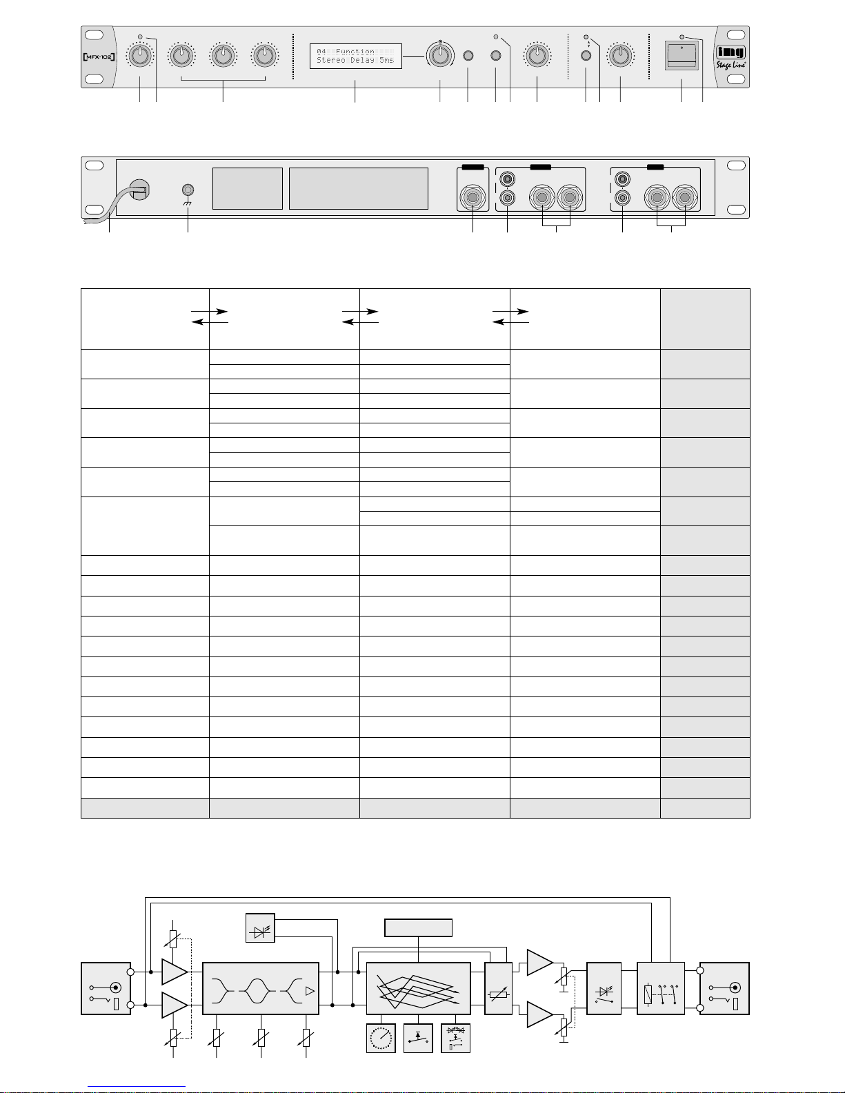
12 3 4 5 6 78 9 101112 1314
➀
➁
EFFECT SELECT
PUSH – ENTER
ESC EFFECT
MIX LEVEL
LEVEL
OUTPUT
DSP EFFECTS
POWER
GREEN:ON
RED:O FF
PHASE
0°
180°
010
5
DRY EFF
PROFESSIONAL DSP MULTI EFFECT UNIT
PEAK
GAIN LOW
INPUT
MIN MAX –12+12
0
MID
–12+12
0
HIGH
–12+12
0
15 16 17 18 19 20 21
230V~/50Hz
EFFECT ON/OFF
RIGHT LEFT/
MONO
RIGHT LEF T
INPUT
RIGHT LEFT/
MONO
RIGHT LEF T
OUTPUTREMOTE
TONE CONTROL ±12dB
DSP CIRCUIT
MIX
LEVEL
HARD
BYPASS
PHASE
REVERSE
ESCEFFECT SELECT
PUSH - ENTER
LCD DISPLAY
PEAK
L
R
OUTPUT
TERMINAL
INPUT
TERMINAL
LEVEL
R
L
GAIN
EFFECT
ON/OFF
Blockschaltbild• Block diagram
Schéma-bloc • Schema a blocchi • Blokschema
➃
Ebene
Level
Niveau
1
Livello
Niveau
234
Voreinstellung
Preset value
Préréglage
Default
Vorinstelling
01 Delay
10ms/Step Time: 0, 10, 20 ... 670, 680ms
—
100ms
02 Ping Pong Delay
10ms/Step Time: 0, 10, 20 ... 570, 580ms
— 250ms
03 Stereo Delay 2ms
10ms/Step Time: 0, 10, 20 ... 670, 680ms
—
10ms
04 Stereo Delay 5ms
10ms/Step Time: 0, 10, 20 ... 670, 680ms
—
30ms
05 Stereo Delay 10ms
10ms/Step Time: 0, 10, 20 ... 670, 680ms
—
100ms
06 Echo
Time
10ms/Step Time: 0, 10, 20 ... 670, 680ms
180ms
07 Reverb Plate — — —
—
15 Auto Pan Time:100, 200 ... 9800, 9900ms — —
500ms
16 Flanger Time:100, 200 ... 9800, 9900ms — —
1000ms
17 Leslie Time:100, 200 ... 9800, 9900ms — —
2000ms
18 Pitch Shifter Scale:
-
100, -90 ... +90, +100 — — +00
19 Preset Param Yes? — — —
1ms/Step
ENTER
ESC
ENTER
ESC
ENTER
ESC
08 Reverb Vocal — — — —
09 Reverb Garage — — —
—
10 Reverb Club — — —
—
11 Reverb Stadium — — —
—
12 Reverb Theater — — —
—
13 Reverb Hall — — —
—
Feedback
14 Reverb Church — — —
—
50%
Time: 0, 01, 02 ... 679, 680ms
1ms/Step
1ms/Step
1ms/Step
1ms/Step
Time: 0, 01, 02 ... 579, 580ms
Time: 0, 01, 02 ... 679, 680ms
Time: 0, 01, 02 ... 679, 680ms
Time: 0, 01, 02 ... 679, 680ms
—Feedback: 0, 1, 2 ... 98, 99%
1ms/Step Time: 0, 01, 02 ... 679, 680ms
Effektübersicht und Bedienstruktur • List of effects and operating structure • Détail des effets et structure de fonctionnement
Panoramica degli effetti e struttura dei comandi • Overzicht van effecten en de bedieningsstructuur
➂

Bitte klappen Sie die Seite 3 heraus. Sie sehen
dann immer die beschriebenen Bedienelemente
und Anschlüsse.
1 Übersicht der Bedienelemente und
Anschlüsse
1.1 Frontseite
1 Regler GAIN zum Anpassen des Eingangspe-
gels; bei Übersteuerung leuchtet die rote LED
PEAK (2) auf – dann den Regler zurückdrehen
2 Übersteuerungsanzeige PEAK
3 3fache Klangregelung: Tiefenregler (LOW), Mit-
tenregler (MID) und Höhenregler (HIGH)
4 Display
5 Dreh-/Druckschalter EFFECT SELECT zur Ef-
fekteinstellung (siehe Bedienstruktur Abb. 3)
drehen: Effekt (auf Ebene 1) bzw. Parameter (ab
Ebene 2) auswählen oder verändern
drücken: Enter = auf eine höhere Bedienebene
schalten
6 Taste ESC zum Zurückschalten auf eine niedri-
gere Bedienebene (siehe Bedienstruktur Abb. 3)
7 Taste EFFECT zum Ein- und Ausschalten des
eingestellten Effekts; die LED (8) über der Taste
zeigt den Schaltzustand an
8 LED zur Anzeige Effekt Ein/Aus
rot: Effekt ausgeschaltet
grün: Effekt eingeschaltet
9 Regler MIX LEVEL zum Einstellen des Verhält-
nisses von Direkt-/Effektsignal am Ausgang
(Effektintensität)
Position DRY: kein Effekt
Position EFF: nur das Effektsignal ist hörbar
Mittelposition: Direkt- und Effektsignal sind zu
gleichen Anteilen gemischt
10 Umschalter PHASE für die Phasenlage am Aus-
gang
Taste gedrückt: Phasenlage um 180° gedreht
nicht gedrückt: Phasenlage nicht gedreht
11 Kontroll-LED leuchtet, wenn der Schalter PHASE
(10) gedrückt ist = Phasenlage um 180° gedreht
12 Regler LEVELfür den Ausgangspegel
13 Ein-/Ausschalter POWER
14 Betriebsanzeige
1.2 Rückseite
15 Netzkabel zum Anschluß an eine Steckdose
(230V~/50Hz)
16 Klemmschraube für einen eventuellen Masse-
anschluß (bei Brummproblemen)
17 6,3-mm-Klinkenbuchse REMOTE zum Anschluß
eines Fußtasters zum ferngesteuerten Ein-/Ausschalten des Effekts – wie mit der Taste EFFECT
(7)
18 Stereo-Ausgang über Cinch-Buchsen
19 Ausgang über 6,3-mm-Klinkenbuchsen
wird nur die Buchse LEFT/ MONO angeschlossen, liegt an dieser Buchse das Mono-Signal aus
der Summe des linken und rechten Kanals an;
beim Anschluß der Buchse LEFT/ MONO werden die Cinch-Ausgangsbuchsen (18) abgeschaltet
20 Stereo-Eingang über Cinch-Buchsen
21 Eingang über 6,3-mm-Klinkenbuchsen
wird nur die Buchse LEFT/ MONO angeschlossen, ist automatisch das Eingangssignal auch
auf den rechten Kanal geschaltet;
beim Anschluß der Buchse LEFT/ MONO werden die Cinch-Eingangsbuchsen (20) abgeschaltet
2 Hinweise für den sicheren Gebrauch
Dieses Gerät entspricht der Richtlinie für elektromagnetische Verträglichkeit 89/ 336/ EWG und der
Niederspannungsrichtlinie 73/23/EWG.
Beachten Sie auch unbedingt die folgenden Punkte:
●
Verwenden Sie das Gerät nur im Innenbereich.
Schützen Sie es vor Tropf- und Spritzwasser,
hoher Luftfeuchtigkeit und Hitze (zulässiger Einsatztemperaturbereich 0– 40°C).
●
Stellen Sie keine mit Flüssigkeit gefüllten Gefäße,
z.B. Trinkgläser, auf das Gerät.
●
Nehmen Sie das Gerät nicht in Betrieb bzw. ziehen Sie sofort den Netzstecker, wenn:
1. sichtbare Schäden am Gerät oder an der Netzanschlußleitung vorhanden sind,
2. nach einem Sturz oder ähnlichem der Verdacht
auf einen Defekt besteht,
3. Funktionsstörungen auftreten.
Lassen Sie das Gerät in jedem Fall in einer Fachwerkstatt reparieren.
●
Eine beschädigte Netzanschlußleitung darf nur
durch den Hersteller oder eine autorisierte Fachwerkstatt ersetzt werden.
●
Ziehen Sie den Netzstecker nie an der Zuleitung
aus der Steckdose.
●
Verwenden Sie für die Reinigung nur ein trockenes, weiches Tuch, auf keinen Fall Chemikalien
oder Wasser.
●
Wird das Gerät zweckentfremdet, falsch bedient
oder nicht fachgerecht repariert, kann für eventuelle Schäden keine Haftung übernommen werden.
Achtung! Das Gerät wird mit lebensgefährlicher
Netzspannung (230 V~) versorgt. Nehmen Sie deshalb nie selbst Eingriffe im
Gerät vor. Durch unsachgemäßes Vorgehen besteht die Gefahr eines elektrischen Schlages. Außerdem erlischt
beim Öffnen des Gerätes jeglicher
Garantieanspruch.
Please unfold page 3. Then you can always see
the operating elements and connections described.
1 Operating Elements and Connections
1.1 Front panel
1 GAIN control to match the input level;
in case of overload, the red LED PEAK (2) lights
up – in this case turn back the control
2 Overload LED PEAK
3 3-way equalizer: bass control (LOW), midrange
control (MID), and treble control (HIGH)
4 Display
5 Rotary switch/ push-button switch EFFECT SE-
LECT for effect adjustment (see operating structure fig. 3)
turn: select effect (on level 1) or select or
change parameter (starting on level 2)
press: Enter = switch to a higher operating
level
6 ESC button to switch back to a lower operating
level (see operating structure fig. 3)
7 EFFECTbutton to switch on and off the adjusted
effect; the LED (8) above the button indicates the
switching status
8 LED to indicate effect on/off
red: effect switched off
green: effect switched on
9 Control MIX LEVELto adjust the ratio of direct sig-
nal to effect signal at the output (effect intensity)
position DRY: no effect
position EFF: only the effect signal is audible
mid-position: direct signal and effect signal
are mixed in equal proportions
10 PHASE selector for the phase at the output
button pressed: phase turned by 180°
not pressed: phase not turned
11 Indicating LED lights up if the PHASE button (10)
is pressed = phase turned by 180°
12 LEVELcontrol for the output level
13 POWER switch
14 Operating LED
1.2 Rear panel
15 Mains cable for connection to a mains socket
(230V~/50Hz)
16 Clamping screw for a ground connection, if
required (in case of hum problems)
17 6.3 mm jack REMOTE to connect a momentary
action foot switch for switching on or off the effect
via remote control – identical with the EFFECT
button (7)
18 Stereo output via phono jacks
19 Output via 6.3mm jacks
if only the jack LEFT/MONO is connected, only
the mono signal from the master of the left and
right channel is applied to this jack;
when connecting the jack LEFT/MONO, the
phono output jacks (18) are switched off
20 Stereo input via phono jacks
21 Input via 6.3mm jacks
if only the jack LEFT/ MONO is connected, the
input signal is automatically switched to the right
channel as well;
when connecting the jack LEFT/MONO, the
phono input jacks (20) are switched off
2 Safety Notes
The unit corresponds to the directive for electromagnetic compatibility 89/ 336 /EEC and to the low
voltage directive 73/23/EEC.
The following items must be observed in any case:
●
The unit is suitable for indoor use only. Protect it
against dripping water and splash water, high
humidity, and heat (ambient temperature range
0–40°C).
●
Do not place any vessels filled with liquid,
e.g. drinking glasses, on the unit.
●
Do not operate unit or immediately disconnect the
plug from the mains socket
1. if there is visible damage to the unit or to the
mains cable,
2. if a defect might have occurred after the unit
was dropped or suffered a similar accident,
3. if malfunctions occur.
In any case the unit must be repaired by skilled
personnel.
●
A damaged mains cable must be replaced by the
manufacturer or by skilled personnel only.
●
Never pull the mains cable to disconnect the
mains plug from the socket.
●
For cleaning only use a dry, soft cloth, by no
means chemicals or water.
●
If the unit is used for other purposes than originally
intended, if it is not correctly operated or not repaired by skilled personnel, no liability for any
damage will be accepted.
●
If the unit is to be put out of operation definitively,
take it to a local recycling plant for disposal.
Attention!The unit is supplied with hazardous
mains voltage (230V~). Leave servicing
to skilled personnel only. Inexpert handling may cause an electric shock hazard.
Furthermore, any guarantee claim will
expire if the unit has been opened.
4
GB
D
A
CH

●
Soll das Gerät endgültig aus dem Betrieb genommen werden, übergeben Sie es zur Entsorgung
einem örtlichen Recyclingbetrieb.
3 Einsatzmöglichkeiten
Der MFX-102 ist ein digitales Stereo-Effektgerät mit
18 Effekten, deren Parameter z. T. eingestellt werden können (siehe Tabelle Abb. 3). Die Einstellungen bleiben auch nach dem Ausschalten des
Gerätes gespeichert. Die Effekte und die Einstellparameter werden über das alphanumerische Display angezeigt.
Das Gerät ist für die Montage in ein Rack
(482mm/19") vorgesehen, kann aber auch als freistehendes Tischgerät verwendet werden. Für den
Einbau in ein Rack wird 1HE benötigt (HE =
Höheneinheit = 44,45mm).
4 Effektgerät anschließen
Vor dem Anschluß bzw. vor dem Verändern von
Anschlüssen das Effektgerät und alle anderen
Audiogeräte ausschalten.
1) Über die Eingangsbuchsen INPUT (20 oder 21)
und die Ausgangsbuchsen OUTPUT(18 oder 19)
das Effektgerät in den Effektweg eines Misch-
pultes oder eines Instrumentenverstärkers ein-
schleifen bzw. es zwischen zwei Geräte mit Line-
Ein- und Ausgang schalten (z.B. zwischen
Mischpult und Verstärker oder zwischen Musikin-
strument und Mischpult).
Hinweise:
a) Bei einem Mono-Eingangssignal dieses auf
die Klinkenbuchse LEFT/ MONO (21) geben.
Die Buchse RIGHT darf hierbei nicht angeschlossen werden. Das Signal wird so auch
auf den rechten Kanal geschaltet. An den Ausgängen (18 oder 19) ist dann je nach eingestelltem Effekt ein Stereo-Signal verfügbar.
b) Wird ein Mono-Ausgangssignal benötigt,
kann dieses an der Klinkenbuchse
LEFT/MONO (19) abgenommen werden. Die
Buchse RIGHT darf hierbei nicht angeschlossen werden.
c) Beim Anschluß der Klinkeneingangsbuchse
LEFT/MONO (21) werden die Cinch-Eingangsbuchsen (20) abgeschaltet und beim Anschluß
der Klinkenausgangsbuchse LEFT/MONO (19)
die Cinch-Ausgangsbuchsen (18).
2) Die Funktion Effekt Ein /Aus läßt sich über einen
Fußtaster (z. B. FS-60 von MONACOR) fernbedienen. Den Fußtaster an die Buchse REMOTE
(17) anschließen.
3) Zuletzt den Netzstecker des Netzanschlußkabels
(15) in eine Steckdose stecken (230V~/50Hz).
5 Bedienung
Vor dem ersten Einschalten des Effektgeräts die
Regler GAIN (1) und LEVEL (12) sowie die Klangregler LOW, MID und HIGH (3) in die Mittelstellung
drehen. Das Gerät mit dem Schalter POWER (13)
einschalten. Die Betriebsanzeige (14) leuchtet, und
im Display (4) erscheint die Begrüßung „Welcome
IMG Stage Line“. Das Gerät ist nach dem Einschalten für einige Sekunden stummgeschaltet. Danach
schaltet sich der zuletzt angewählte Effekt ein. Die
Status-LED (8) leuchtet grün.
Hinweis: Wenn das Effektgerät ausgeschaltet ist,
wird das Eingangssignal unbeeinflußt auf den Ausgang gegeben.
5.1 Pegel, Phasenlage und Klang einstellen
1) Stehen die Regler GAIN (1) und LEVEL (12) in
der Mittelstellung, ist der Ausgangspegel gleich
dem Eingangspegel.
Wird das Effektgerät durch einen zu großen
Eingangspegel übersteuert, leuchtet die PEAKLED (2) auf. Den Regler GAIN soweit zurückdrehen, bis die PEAK-LED erlischt. Entsprechend
den Regler LEVELaufdrehen, um den Ausgangspegel wieder anzuheben. Das nachfolgende Gerät darf jedoch nicht übersteuert werden.
Bei einem geringen Eingangspegel ergibt sich
ein schlechter Störabstand. Den Regler GAIN
weiter aufdrehen, die PEAK-LED darf aber nicht
aufleuchten. Entsprechend den Regler LEVEL
zudrehen, um den Ausgangspegel wieder abzusenken, jedoch nicht, wenn das nachfolgende
Gerät einen höheren Eingangspegel benötigt.
2) Wenn in dem Signalweg, in dem das Effektgerät
zwischengeschaltet ist, eine Phasendrehung des
Signals erfolgt, kann es in Verbindung mit anderen Signalwegen zu Klangverfälschungen kommen. Mit dem MFX-102 läßt sich die Phasenlage
erneut drehen, so daß sie wieder korrekt ist.
Dazu die Taste PHASE (10) hineindrücken. Die
LED (11) über der Taste leuchtet. Im Zweifelsfall
kann durch Ein- und Ausrasten der Taste PHASE
die richtige Phasenlage nach Gehör ermittelt
werden.
3) Um den Klang zu beeinflussen, mit den drei
Klangreglern LOW, MID und HIGH (3) die Bässe,
Mitten und Höhen anheben oder absenken. Bei
einer starken Anhebung kann des Gerät übersteuert werden, dann den Regler GAIN entsprechend zurückdrehen.
5.2 Effektauswahl und -einstellung
1) Durch Drehen des Schalters EFFECT SELECT
(5) den gewünschten Effekt auswählen – siehe
auch zur Übersicht Abb. 3.
— Bei den Ef fekten „Stereo Delay“ 03 bis 05 wird
zusätzlich zu der einstellbaren Grundverzögerung zwischen 0ms und 680 ms der linke
Kanal um 2 ms, 5 ms oder 10 ms gegenüber
dem rechten Kanal verzögert.
— Die Funktion 19 „Preset Param“ dient zur
Rückstellung aller Parameter auf die Voreinstellung – siehe Kap. 5.3.
2) Damit der Effekt hörbar ist, muß die Status-LED
(8) grün leuchten. Die Taste EFFECT (7) ggf.
drücken. Mit dieser Taste oder mit einem eventuell angeschlossenen Fußtaster kann der Effekt
●
Important for U.K. Customers!
The wires in this mains lead are coloured in accordance with the following code:
blue = neutral
brown = live
As the colours of the wires in the mains lead of this
appliance may not correspond with the coloured
markings identifying the terminals in your plug,
proceed as follows:
1. The wire which is coloured blue must be connected to the terminal in the plug which is
marked with the letter N or coloured black.
2. The wire which is coloured brown must be connected to the terminal which is marked with the
letter L or coloured red.
3 Applications
MFX-102 is a digital stereo effect unit with 18 effects
whose parameters can partly be adjusted (see table
fig. 3). The adjustments are kept memorized even
after switching off the unit. The effects and the adjusting parameters are shown on the alphanumeric
display.
The unit is designed for mounting into a rack
(482mm/19"), but it can also be used as a table top
unit. For rack installation, 1 rack space (= 44.45mm)
is required.
4 Connecting the Effect Unit
Prior to making or to changing any connections,
switch off the effect unit and all other audio units.
1) Via the input jacks INPUT (20 or 21) and the out-
put jacks OUTPUT (18 or 19), insert the effect
unit into the effect way of a mixer or of the ampli-
fier of an instrument or connect it between two
units with line input and output (e. g. between
mixer and amplifier or between musical instru-
ment and mixer).
Notes:
a) In case of a mono input signal, feed this
signal to the jack LEFT/MONO (21). For this
purpose, the jack RIGHT must not be connected. The signal is switched to the right channel
anyway. According to the adjusted effect, a
stereo signal will then be available at the outputs (18 or 19).
b) If a mono output signal is required, this sig-
nal can be collected at the jack LEFT/MONO
(19). For this purpose, the jack RIGHT must
not be connected.
c) When connecting the input jack LEFT/MONO
(21), the phono input jacks (20) are switched
off; when connecting the output jack
LEFT/MONO (19) the phono output jacks (18)
are switched off.
2) The function effect on/off can be remote-controlled via a momentary action foot switch (e. g.
MONACOR FS-60). Connect the momentary
action foot switch to the jack REMOTE (17).
3) Finally connect the plug of the mains cable (15)
to a mains socket (230V~/50Hz).
5 Operation
Prior to switching on the effect unit for the first time,
turn the controls GAIN (1) and LEVEL (12) and the
equalizer controls LOW, MID, and HIGH (3) to midposition. Switch on the unit with the POWER switch
(13). The operating LED (14) lights up and the display (4) shows the greeting “Welcome IMG Stage
Line”. After switching on, the unit is muted for a few
seconds. After that, the last selected effect is
switched on. The status LED (8) shows green.
Note: If the effect unit is switched off, the input
signal is fed to the output without being influenced.
5.1 Adjusting level, phase, and sound
1) If the controls GAIN (1) and LEVEL (12) are in
mid-position, the output level is equal to the input
level.
If the effect unit is overloaded due to an input
level that is too high, the PEAK LED (2) lights up.
Turn back the GAIN control until the PEAK LED is
extinguished. Advance the LEVEL control correspondingly to boost the output level again. However, the subsequent unit must not be overloaded.
With a low input level, a poor S/ N ratio will
result. Turn up the GAIN control, however, the
PEAK LED must not light up. Turn back the
LEVEL control correspondingly to attenuate the
output level again, but do not follow this procedure if the subsequent unit requires a higher
input level.
2) If on the signal way where the effect unit is inserted, a phase reversal of the signal occurs, the
sound may deteriorate in connection with other
signal ways. By means of the MFX-102, the
phase can be reversed so that it is correct again.
For this purpose, lock the button PHASE (10).
The LED (11) above the button lights up. In case
of doubt, determine the correct phase by locking
and unlocking the button PHASE according to
your hearing.
3) To influence the sound, use the three equalizer
controls LOW, MID, and HIGH (3) to boost or
attenuate the bass range, the midrange and the
high range. In case of substantial boosting, the
unit may be overloaded. In this case, turn back
the GAIN control correspondingly.
5.2 Selecting and adjusting the effects
1) Select the desired effect by turning the switch
EFFECT SELECT (5) – also see fig. 3 for details.
— In case of the effects “Stereo Delay” 03 to 05,
in addition to the adjustable basic delay between 0 ms and 680 ms, the left channel is
delayed by 2ms, 5 ms, or 10ms compared to
the right channel.
— The function 19 “Preset Param” serves to
reset all parameters to the preset values – see
chapter 5.3.
2) For an audible effect, the status LED (8) must
show green. Press the button EFFECT (7), if
required. By means of this button or a momentary
5
GB
D
A
CH
 Loading...