

IMG STAGE LINE MCX-3210 Instruction Manual
Stage Line
R
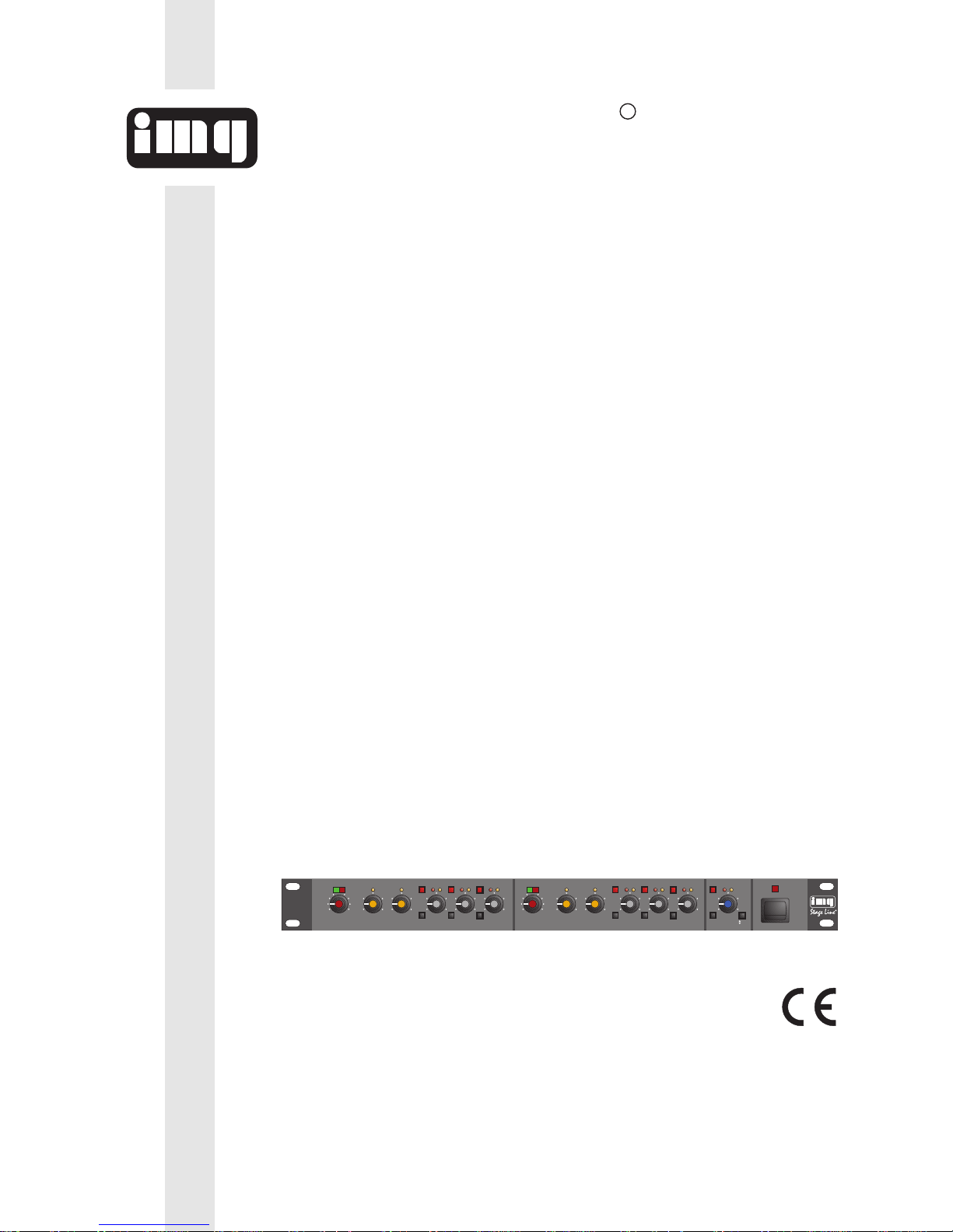
MCX-3210
3-WAY/2-WAY
ACTIVE
CROSSOVER
dB
-20
0
-13
-10 -5
-2
PHASE
NORM.
REV.
MUTE
ON
POWER
-6dB CLIP
INPUT GAIN CROSSOVER FREQUENCY LOW
MID HIGH
dB
-10 +10Hz70 1k
100
300 450
800
Hz
910 8 k
1.2k
3k 4k
6k
dB
0
-13
-10 -5
-2
PHASE
dB
0
-13
-10 -5
-2
PHASE
dB
0
-13
-10 -5
-2
PHASE
-20-20-20
MUTE MUTE MUTE
-6dB CLIP
INPUT GAIN CROSSOVER FREQUENCY LOW
MID HIGH
dB
-10 +10Hz70 1k
100
300 450
800
Hz
910 8 k
1.2k
3k 4k
6k
dB
0
-13
-10 -5
-2
PHASE
dB
0
-13
-10 -5
-2
PHASE
dB
0
-13
-10 -5
-2
PHASE
-20-20-20
MUTE MUTE MUTE
OUTPUT LEVEL
CHANNEL1 CHANNEL2 MONO SUB
MCX-3210 Best.-Nr. 24.2930
ELEKTRONISCHE FREQUENZWEICHE
ELECTRONIC CROSSOVER NETWORK
FILTRE DE FREQUENCES ACTIF
FILTRO ELETTRONICO
BEDIENUNGSANLEITUNG • INSTRUCTION MANUAL • MODE D`EMPLOI
ISTRUZIONI PER L´USO • GEBRUIKSAANWIJZING • HANDLEIDING • MANUAL DE INSTRUCCIONES
BRUGSANVISNING • BRUKSANVISNING • KÄYTTÖOHJE

2
Stage Line
R
Bevor Sie einschalten ...
Wir wünschen Ihnen viel Spaß mit Ihrem neuen Gerät
von „img Stage Line“. Dabei soll Ihnen diese Bedienungsanleitung helfen, alle Funktionsmöglichkeiten
kennenzulernen. Die Beachtung der Anleitung vermeidet
außerdem Fehlbedienungen und schützt Sie und Ihr
Gerät vor eventuellen Schäden durch unsachgemäßen
Gebrauch.
Den deutschen Text finden Sie auf den Seiten 4 –6.
Before you switch on ...
We wish you much pleasure with your new unit by “img
Stage Line”. With these operating instructions you will be
able to get to know all functions of the unit. By following
these instructions false operations will be avoided, and
possible damage to you and your unit due to improper
use will be prevented.
You will find the English text on the pages 4–6.
D
A
CH
GB
Avant toute mise en service ...
Nous vous remercions d’avoir choisi un appareil “img
Stage Line” et vous souhaitons beaucoup de plaisir à l’utiliser. Cette notice a pour objectif de vous aider à mieux
connaître les multiples facettes de l’appareil et à vous
éviter toute mauvaise manipulation.
La version française se trouve pages 7– 9.
Prima di accendere ...
Vi auguriamo buon divertimento con il Vostro nuovo
apparecchio “img Stage Line”. Le istruzioni per l’uso Vi
possono aiutare a conoscere tutte le possibili funzioni. E
rispettando quanto spiegato nelle istruzioni, evitate di
commettere degli errori, e così proteggete Voi stessi, ma
anche l’apparecchio, da eventuali rischi per uso improprio.
Il testo italiano lo potete trovare alle pagine 7– 9.
F
B
CH
I
Voordat u inschakelt ...
Wij wensen u veel plezier met uw nieuw toestel van “img
Stage Line”. Met behulp van bijgaande gebruiksaanwijzing kunt u alle functiemogelijkheden leren kennen. Door
deze instructies op te volgen zal een slechte werking
vermeden worden, en zal een eventueel letsel aan uzelf
en schade aan uw toestel tengevolge van onzorgvuldig
gebruik worden voorkomen.
U vindt de nederlandstalige tekst op de pagina’s 10– 12.
Antes de cualquier instalación
Tenemos de agradecerle el haber adquirido un equipo
“img Stage Line” y le deseamos un agradable uso. Este
manual quiere ayudarle a conocer las multiples facetas
de este equipo y evitar cualquier uso inadecuado.
La versión española se encuentra en las páginas
10– 12.
NL
B
E
Inden De tænder for apparatet ...
Vi ønsker Dem god fornøjelse med Deres nye “img
Stage Line” apparat. Denne brugsanvisning giver mulighed for at lære alle apparatets funktioner at kende. Følg
vejledningen for at undgå forkert betjening og for at beskytte Dem og Deres apparat mod skade på grund af forkert brug.
Den danske tekst finder De på side 13– 15.
Förskrift
Vi önskar dig mycket nöje med din nya enheten från “img
Stage Line”. Om du först läser instruktionerna kommer
du att glädje av enheten under lång tid. Kunskap om alla
funktioner kan bespara dig mycket besvär med enheten
i framtiden.
Du finner den svenska texten på sidan 13– 15.
DK
S
Ennen virran kytkemistä ...
T oivomme, että uusi “img Stage Line”-laitteesi tuo sinulle
paljon iloa ja hyötyä. Tämä käyttöohje esittää sinulle
kaikki uuden laitteesi toiminnot. Seuraamalla sitä vältät
virhetoiminnot ja niistä johtuvat mahdolliset vahingot
sinulle tai laitteellesi.
Löydät suomenkieliset käyttöohjeet sivuilta 16– 17.
FIN
3
➀
➁
MCX-3210
3-WAY/2-WAY
ACTIVE
CROSSOVER
-6dB CLIP
INPUT GAIN CROSSOVER FREQUENCY LOW
MID HIGH
dB
-10 +10Hz70 1k
100
300 450
800
Hz
910 8k
1.2k
3k 4k
6k
dB
0
-13
-10 -5
-2
PHASE
dB
0
-13
-10 -5
-2
PHASE
dB
0
-13
-10 -5
-2
PHASE
-20-20-20
MUTE MUTE MUTE
-6dB CLIP
INPUT GAIN CROSSOVER FREQUENCY LOW
MID HIGH
dB
-10 +10Hz70 1K
100
300 450
800
Hz
910 8k
1.2k
3k 4k
6k
dB
0
-13
-10 -5
-2
PHASE
dB
0
-13
-10 -5
-2
PHASE
dB
0
-13
-10 -5
-2
PHASE
-20-20-20
MUTE MUTE MUTE
ON
POWER
CHANNEL1 CHANNEL2 MONO SUB
OUTPUT LEVEL
NORM.
REV.
PHASE
MUTE
-10 -5
-2
0
dB
-20
-13
12 3412 34567
8 9 10 11 12 8 9 10 11 12 13 14 15
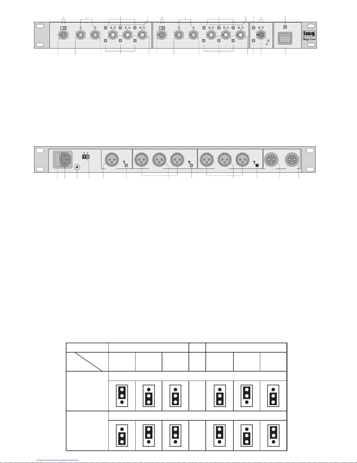
2-WAY MODE / JUMPER SELECTION
CROSSOVER FREQUENCY - 70 Hz TO 1 KHz
CROSSOVER FREQUENCY - 910 Hz TO 8 KHz
CHANNEL 1 CHANNEL 2
J 1 J 2 J 3 J 4 J 5 J 6
JUMPER
2-WAY
MODE
MODE 1
(FACTORY
SETTINGS)
MODE 2
1
11 1
1
1
1
11
1
1
1
➂
GROUND FLOAT
230 V~, 50 Hz
T100 mA
SUB
MONO OUT
80 Hz
120 Hz
HIGH MID LOW
3 WAY
2 WAY
CHANNEL 2 OUT
HIGH MID LOW
3 WAY
2 WAY
CHANNEL 1 OUT CHANNEL 1
IN IN
CHANNEL 2
16 17 18 19 20 21 22 23 24 25 26 27

Bitte klappen Sie die Seite 3 heraus. Sie sehen
dann immer die beschriebenen Bedienelemente
und Anschlüsse.
1 Übersicht der Bedienelemente und
Anschlüsse
1.1 Frontseite
1 Pegelanzeigen für die Eingänge
2 Statusanzeigen für die Einstellregler der Trenn-
frequenzen:
bei 3-Wege-Betrieb leuchten beide LEDs,
bei 2-Wege-Betrieb leuchtet nur eine LED.
3 Mute-Tasten zum Stummschalten der Kanäle
LOW, MID und HIGH
4 LEDs für die Statusanzeige der Kanäle LOW,
MID und HIGH
rot: Kanal stummgeschaltet
gelb: Kanal in Betrieb
5 Mute-Taste zum Stummschalten des Subwoofer-
Kanals
6 LEDs für die Statusanzeige des Subwoofer-
Kanals
rot: Kanal stummgeschaltet
gelb: Kanal in Betrieb
7 Betriebsanzeige
8 Pegelregler für die Eingänge
9 Einstellregler für die Trennfrequenz LOW/MID
10 Einstellregler für die Trennfrequenz MID/HIGH
11 Umschalter für die Phasenlage der Kanäle LOW,
MID und HIGH
nicht gedrückt: keine Phasendrehung
gedrückt: 180°-Phasendrehung
12 Pegelregler für die Ausgänge LOW, MID und
HIGH
13 Umschalter für die Phasenlage des Subwoofer-
Kanals
nicht gedrückt: keine Phasendrehung
gedrückt: 180°-Phasendrehung
14 Pegelregler für den Subwoofer-Ausgang
15 Ein-/Ausschalter
1.2 Rückseite
16 Sicherungshalter
17 Anschluß für das Netzkabel
18 Anschluß für gemeinsamen Erdungspunkt
19 Ground-Lift-Schalter zum Trennen der Signal-
masse von der Erdung (Gehäuse), um Masseschleifen zu vermeiden (Position FLOAT)
20 Ausgang des Subwoofer-Kanals, symmetrisch
21 Taste für die Grenzfrequenz des Subwoofers
nicht gedrückt: 80Hz
gedrückt: 120Hz
22 Ausgänge für Kanal2 LOW, MID und HIGH, sym-
metrisch
23 Betriebsartschalter für Kanal 2
nicht gedrückt: 3-Wege-Betrieb
gedrückt: 2-Wege-Betrieb
24 Ausgänge für Kanal1 LOW, MID und HIGH, sym-
metrisch
25 Betriebsartschalter für Kanal 1
nicht gedrückt: 3-Wege-Betrieb
gedrückt: 2-Wege-Betrieb
26 Eingang Kanal 2, symmetrisch
27 Eingang Kanal 1, symmetrisch
2 Hinweise für den sicheren Gebrauch
Dieses Gerät entspricht der Richtlinie für elektromagnetische Verträglichkeit 89/ 336/ EWG und der Niederspannungsrichtlinie 73/23/EWG.
Das Gerät wird mit lebensgefährlicher Netzspannung (230 V~) versorgt. Nehmen Sie deshalb nie
selbst Eingriffe im Gerät vor. Durch unsachgemäßes Vorgehen besteht die Gefahr eines elektrischen Schlages. Außerdem erlischt beim Öffnen
des Gerätes jeglicher Garantieanspruch.
Beachten Sie auch unbedingt die folgenden Punkte:
●
Das Gerät ist nur zur Verwendung in Räumen geeignet. Schützen Sie es vor Feuchtigkeit und Hitze
(zulässiger Einsatztemperaturbereich 0
-
40°C).
●
Nehmen Sie das Gerät nicht in Betrieb, bzw. ziehen Sie sofort den Netzstecker, wenn:
1. sichtbare Schäden am Gerät oder an der Netzanschlußleitung vorhanden sind,
2. nach einem Sturz oder ähnlichem der Verdacht
auf einen Defekt besteht,
3. Funktionsstörungen auftreten.
Lassen Sie das Gerät in jedem Fall in einer Fachwerkstatt reparieren.
●
Ziehen Sie den Netzstecker nie an der Zuleitung
aus der Steckdose.
●
Wird das Gerät zweckentfremdet, nicht richtig angeschlossen, falsch bedient oder nicht fachgerecht
repariert, kann für eventuelle Schäden keine Haftung übernommen werden.
●
Verwenden Sie zum Reinigen nur ein trockenes,
weiches Tuch, niemals Chemikalien oder Wasser.
●
Soll das Gerät endgültig aus dem Betrieb genommen werden, übergeben Sie es zur Entsorgung einem örtlichen Recyclingbetrieb.
3 Einsatzmöglichkeiten
Mit der elektronischen Frequenzweiche MCX-3210
können Stereo-Audioanlagen im 3-Wege- oder 2-Wege-Betrieb mit oder ohne zusätzlichem Subwoofer
realisiert werden. Die Weiche ist speziell für den professionellen Einsatz auf der Bühne, in der Disco und
für die PA-Beschallung entwickelt. Durch die vielfältigen Einstellmöglichkeiten wird immer eine optimale
Anpassung für die unterschiedlichsten Anwendungen
erreicht.
Die Frequenzaufteilung erfolgt mit „Active State
Variable“-Filtern, die für nahtlose Übergänge sorgen.
Alle Ein- und Ausgänge sind symmetrisch (XLRBuchsen), können aber auch asymmetrisch beschaltet werden.
Please unfold page 3. Then you can always see the
operating elements and connections described.
1 Operating Elements and Connections
1.1 Front panel
1 Level indications for the inputs
2 State indications for the controls to adjust the
crossover frequencies:
with 3-way operation both LEDs light,
with 2-way operation only one LED lights.
3 Mute buttons for muting of the channels LOW,
MID, and HIGH
4 LEDs for the state indications of the channels
LOW, MID, and HIGH
red: channel is muted
yellow: channel is in operation
5 Mute button for muting of the subwoofer channel
6 LEDs for the state indication of the subwoofer
channel
red: channel is muted
yellow: channel is in operation
7 Power LED
8 Level controls for the inputs
9 Controls to adjust the crossover frequency
LOW/MID
10 Controls to adjust the crossover frequency
MID/HIGH
11 Selector switches for the phase conditions of the
channels LOW, MID, and HIGH
not pressed: no phase reversal
pressed: 180° phase reversal
12 Level controls for the outputs LOW, MID, and
HIGH
13 Selector switch for the phase condition of the
subwoofer channel
not pressed: no phase reversal
pressed: 180° phase reversal
14 Level control for the subwoofer output
15 On/Off switch
1.2 Rear panel
16 Fuse holder
17 Connection for the mains cable
18 Connection for common grounding point
19 Ground lift switch for separating the signal ground
from the housing ground to avoid hum loops
(FLOATposition)
20 Output of the subwoofer channel, balanced
21 Button for the cut-off frequency of the subwoofer
not pressed: 80 Hz
pressed: 120 Hz
22 Outputs for channel 2 LOW, MID, and HIGH,
balanced
23 Operating mode switch for channel 2
not pressed: 3-way operation
pressed: 2-way operation
24 Outputs for channel 1 LOW, MID, and HIGH,
balanced
25 Operating mode switch for channel 1
not pressed: 3-way operation
pressed: 2-way operation
26 Input channel 2, balanced
27 Input channel 1, balanced
2 Safety Notes
This unit is in accordance with the directive for electromagnetic compatibility 89/336 / EEC and the low voltage directive 73/23/EEC.
The unit uses lethal mains voltage (230 V~). In
order to prevent an electrical shock hazard, do not
open the cover. Inadequate handling may cause
an electrical shock. Furthermore, upon opening the
cover, any kind of guarantee expires.
Also observe in any case the following points:
●
The unit is suitable for indoor use only. Protect it
against humidity and heat (admissible ambient
temperature 0–40 °C).
●
Do not set the unit into operation or immediately
take the mains plug out of the mains socket if:
1. the unit or the mains connecting cable shows
visible signs of damage,
2. a defect might have occured after a fall or a similar incident,
3. there are malfunctions.
Have the unit in either case repaired in an authorized technical workshop.
●
Do not pull the mains plug out of the socket by
means of the mains cable.
●
If the unit is used for other purposes than originally
intended or if it is wrongly connected, wrongly
operated or not repaired by an expert, no liability
can be assumed for any possible damage.
●
For cleaning use a dry, soft cloth only. Do not use
any chemicals or water.
●
If the unit is to be put out of operation definitively, it
must be disposed of in a local recycling plant.
●
Important for U.K. Customers!
The wires in this mains lead are coloured in accordance with the following code:
green/ yellow = earth; blue = neutral; brown = live
As the colours of the wires in the mains lead of this
appliance may not correspond with the coloured
markings identifying the terminals in your plug, proceed as follows:
1. The wire which is coloured green and yellow
must be connected to the terminal in the plug
which is marked with the letter E or by the earth
symbol or coloured green or green and yel-
low.
2. The wire which is coloured blue must be connected to the terminal which is marked with the
letter N or coloured black.
3. The wire which is coloured brown must be con-
nected to the terminal which is marked with the
letter L or coloured red.
Warning! This appliance must be earthed.
4
GB
D
A
CH
4 Aufstellmöglichkeiten
Die Frequenzweiche ist speziell für die Montage in
ein Rack (482mm /19") ausgelegt. Sie kann bei Bedarf aber auch frei aufgestellt werden. Für den Rackeinbau wird 1Höheneinheit (= 44,5 mm) benötigt.
5 Betriebsmodus einstellen
1) Mit der Taste (21) die Grenzfrequenz für den Subwoofer einstellen (siehe technische Daten des
Subwoofers):
Taste nicht gedrückt: 80 Hz
Taste gedrückt: 120 Hz
2) Mit den Tasten (23 +25) den Betriebsmodus einstellen:
Tasten nicht gedrückt: 3-Wege-Betrieb
Tasten gedrückt: 2-Wege-Betrieb
Bei 2-Wege-Betrieb sind nur die Kanäle LOW und
HIGH aktiv. Zur Kennzeichnung sind die gelben
LEDs (4) über den Reglern MID aus.
3) Bei 2-Wege-Betrieb ist die Trennfrequenz für die
Kanäle LOW und HIGH ab Werk so eingestellt,
daß sie zwischen 70 Hz und 1 kHz mit den Reglern (9) gewählt werden kann. Es leuchten nur die
gelben LEDs (2) über den Reglern (9).
Bei Bedarf kann die Trennfrequenz so eingestellt werden, daß sie zwischen 910Hz und 8 kHz
mit den Reglern (10) gewählt werden kann. Dieses darf nur von einer autorisierten Fachkraft
durchgeführt werden. Dazu das Gerät zuerst von
der Stromversorgung trennen und dann öffnen.
Im Gerät sind die Brücken J1
-
J6 auf MODE 2
nach Abbildung 3 bzw. dem Aufdruck auf dem
Gerät umzustecken. Nach dem Umstecken leuchten bei 2-Wege-Betrieb nur die gelben LEDs (2)
über den Reglern (10).
6 Gerät anschließen
Vor dem Anschluß bzw. vor dem Verändern von Anschlüssen die Frequenzweiche und alle anderen
Audiogeräte ausschalten.
6.1 Eingänge
An die Eingangsbuchsen (26 + 27) die Signalquelle
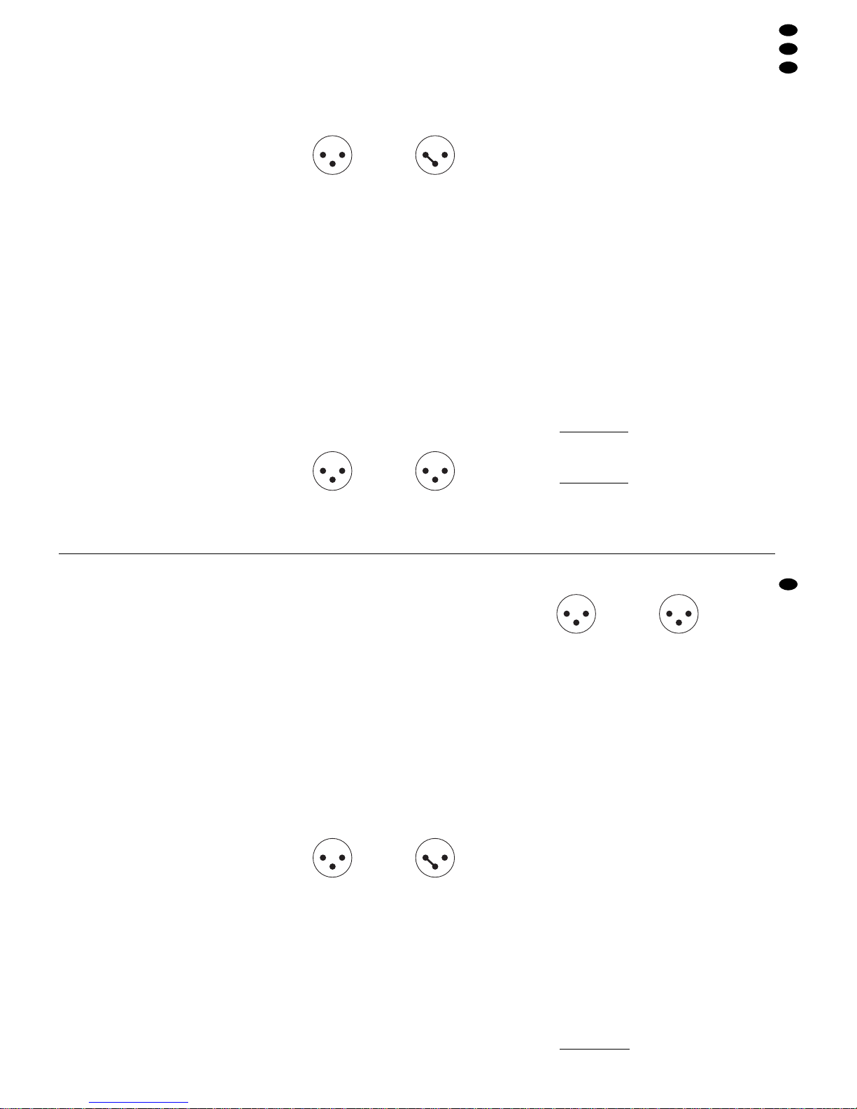
(z.B. Mischpult, Vorverstärker) anschließen. Die Eingänge sind symmetrisch, können aber auch asymmetrisch beschaltet werden. Die Stecker für die Eingangsbuchsen müssen wie abgebildet angeschlossen sein:
symmetrisch asymmetrisch
1 Masse 1 Masse
2 Plus 2 Signal
3 Minus 3 Masse
Damit die Stereokanäle nicht vertauscht werden, ist
zu empfehlen, immer Kanal 1 für den linken Kanal zu
verwenden und Kanal 2 für den rechten Kanal.
6.2 Ausgänge
An die Buchsen (22) die Endverstärker der Kanäle
LOW, MID und HIGH (jeweils für den rechten Kanal)
anschließen und an die Buchsen (24) die entsprechenden Endverstärker für den linken Kanal. Bei
2-Wege-Betrieb sind nur die Ausgänge LOW und
HIGH zu verwenden. Den Verstärker für den Subwoofer an die Buchse (20) anschließen.
Alle Ausgänge sind symmetrisch, können aber
auch asymmetrisch beschaltet werden. Die Stecker
für die Ausgangsbuchsen müssen wie abgebildet angeschlossen sein.
symmetrisch asymmetrisch
1 Masse 1 Masse
2 Plus 2 Signal
3 Minus 3 frei
6.3 Netzanschluß
Zuletzt das beiliegende Netzkabel mit dem Anschluß
(17) verbinden, und den Netzstecker des Kabels in
eine Steckdose (230V~/ 50 Hz) stecken. Die Frequenzweiche aber noch nicht einschalten. Zuerst
muß eine Grundeinstellung erfolgen, siehe Kap. 7.1
„Grundeinstellung“.
7 Frequenzweiche einstellen
7.1 Grundeinstellung
Vor dem ersten Einschalten muß eine Grundeinstellung vorgenommen werden:
1) Die beiden Pegelregler (8) für die Eingänge auf
Minimum (
-
10dB) stellen.
2) Die sechs Pegelregler (12) der Ausgänge LOW,
MID und HIGH sowie den Regelregler (14) für den
Subwoofer-Ausgang auf Minimum (
-
20 dB) stel-
len.
3) Die sechs Mute-Tasten (3) für die Kanäle LOW,
MID und HIGH sowie die Mute-Taste (5) für den
Subwoofer-Kanal dürfen nicht gedrückt sein.
4) Die sechs Tasten PHASE (11) für die Kanäle
LOW, MID und HIGH sowie die Taste PHASE (13)
für den Subwoofer-Kanal dürfen nicht gedrückt
sein, d. h. die Phasenlage der Kanäle wird nicht
verändert.
5) Die Trennfrequenzen sind entsprechend der verwendeten Lautsprecher (siehe technische Daten
der Lautsprecher) und für beide Kanäle gleich einzustellen:
3-Wege-Betrieb
Bei 3-Wege-Betrieb die Trennfrequenz LOW/MID
mit den Reglern (9) und die Trennfrequenz MID /
HIGH mit den Reglern (10) einstellen.
2-Wege-Betrieb
Bei 2-Wege-Betrieb im Modus 1 [Werkseinstel-
lung, LEDs (2) über den Reglern (10) sind aus] die
Trennfrequenz LOW/HIGH mit den Reglern (9)
einstellen. Die Regler (10) sind außer Betrieb.
21
3
21
3
12
3
12
3
3 Applications
With the electronic crossover network MCX-3210
stereo audio systems can be realized in 3-way or
2-way operation with or without additional subwoofer.
The network has especially been designed for the
professional use on stage, in the disco, and for PA
applications. Due to the versatile facilities of adjustment the most different requirements can be met in
an optimum way.
The frequency range limiting is made with “Active
State Variable Filters” which provide perfect transition crossovers. All inputs and outputs are balanced
(XLR jacks) but they can also be used unbalanced.
4 Installation
The crossover network has especially been designed
for the mounting in a rack (482mm/19"). If required,
it can also be used as a free standing crossover network. For the rack installation a height of 1 rack
space (= 44,5mm) is necessary.
5 Adjustment of the Operating Mode
1) With the button (21) adjust the cut-off frequency
for the subwoofer (see subwoofer specifications):
Button not pressed: 80Hz
Button pressed: 120Hz
2) Adjust the operating mode with the buttons
(23+ 25):
Buttons not pressed: 3-way operation
Buttons pressed: 2-way operation
With 2-way operation only the channels LOW and
HIGH are active, the yellow LEDs (4) above the
MID controls do not light.
3) With 2-way operation the crossover frequency for
the channels LOW and HIGH is set in the factory
in such a way that it can be selected between
70Hz and 1 kHz with the controls (9). Just the yel-
low LEDs (2) above the controls (9) are lighting.
If required, the crossover frequency can be adjusted in such a way that it can be selected between 910 Hz and 8 kHz with the controls (10).
This must only be carried out by authorized, skilled
personnel. For this cut off the crossover network
from the power supply and then open it. Inside the
jumpers J1
-
J6 on mode 2 are to be rearranged
according to fig. 3 resp. according to the imprint
on the crossover network. With 2-way operation
just the yellow LEDs (2) above the controls (10)
light after rearranging.
6 Connection of the Crossover Network
Prior to connection or changing of connections
switch off the crossover network and all other audio
units.
6.1 Inputs
Connect the signal source (e.g. mixer, preamplifier) to
the input jacks (26+27). The inputs are balanced, but
they can also be used in an unbalanced way. The
plugs for the input jacks must be connected as follows:
balanced unbalanced
1 ground 1 ground
2 plus 2 signal
3 minus 3 ground
In order not to mix up the stereo channels, it is
recommended always to use channel 1 for the left
channel and channel 2 for the right.
6.2 Outputs
Connect the power amplifiers of the channels LOW,
MID, and HIGH (each for the right channel) to the
jacks (22) and the corresponding power amplifiers for
the left channel to the jacks (24). With 2-way operation only use the outputs LOW and HIGH. Connect
the amplifier for the subwoofer to the jack (20).
All outputs are balanced but they can also be
used in an unbalanced way. The plugs for the output
jacks must be connected as follows:
balanced unbalanced
1 ground 1 ground
2 plus 2 signal
3 minus 3 not connected
6.3 Mains Connection
Finally connect the enclosed mains cable to the connection (17), and put the mains plug of the cable into
a socket (230V~/ 50 Hz). But do not yet switch on the
crossover network. At first a basic adjustment must
be made, see chapter 7.1 “Basic adjustment”.
7 Adjustment of the Crossover Network
7.1 Basic adjustment
Prior to the first switching on a basic adjustment must
be made:
1) Set both level controls (8) for the inputs to minimum (
-
10dB).
2) Set the six level controls (12) of the outputs LOW,
MID, and HIGH as well as the level control (14) for
the subwoofer output to minimum (
-
20dB).
3) The six mute buttons (3) for the channels LOW,
MID, and HIGH as well as the mute button (5) for
the subwoofer channel must not be pressed.
4) The six PHASE buttons (11) for the channels
LOW, MID, and HIGH as well as the PHASE button (13) for the subwoofer channel must not be
pressed, i.e. the phase condition of the channels
is not changed.
5) Adjust the crossover frequencies according to the
speakers used (see specifications of the speakers),
they must be the same for both channels.
3-way operation
With 3-way operation adjust the crossover frequency
LOW/MID with the controls (9) and the crossover
frequency MID/HIGH with the controls (10).
21
3
21
3
12
3
12
3
5
GB
D
A
CH

Bei 2-Wege-Betrieb im Modus 2 [geänderte Einstellung, LEDs (2) über den Reglern (9) sind aus]
die Trennfrequenz LOW/ HIGH mit den Reglern
(10) einstellen. Die Regler (9) sind außer Betrieb.
6) Jetzt kann die komplette Audioanlage in folgender
Reihenfolge (um laute Einschaltgeräusche zu vermeiden) eingeschaltet werden:
1. Signalquelle (z.B. Mischpult, Vorverstärker),
2. Frequenzweiche mit dem Schalter POWER (15),
3. zum Schluß alle Verstärker.
7) Tritt ein Brummen auf, das durch eine Brummschleife entsteht (z.B. Masseverbindung vom Gehäuse über das Rack zu einem anderen Gehäuse),
ist auf der Rückseite der Ground-Lift-Schalter (19)
in Position FLOAT zu schieben. Dadurch wird die
Signalmasse von der Gehäusemasse getrennt.
7.2 Pegel und Phasenlagen einstellen
Zur optimalen Pegeleinstellung sind ein Schallpegelmeßgerät (z.B. SM-4 von MONACOR) und eine
Test-CD (z. B. CD-2CHECK von MONACOR) sehr
hilfreich.
1) Ein Signal auf die Weiche geben. Mit den Reglern
(8) die Eingangspegel nach den Pegelanzeigen (1)
einstellen. Falls die Regler auf Maximum gestellt
werden müssen, ist der Ausgangspegel der Signalquelle zu erhöhen.
2) Die Pegelregler (12 +14) für die Ausgänge auf
0dB stellen. (Bei 2-Wege-Betrieb sind die Regler
für die Kanäle MID außer Betrieb.) Alle MuteTasten (3 +5) drücken. Die Kanäle sind jetzt
stummgeschaltet, und die roten LEDs (4+ 6)
leuchten. Kanal für Kanal mit der entsprechenden
Mute-T aste wieder einschalten, und den Pegel mit
dem dazugehörigen Regler angleichen.
3) Die Phasenlage für jeden Kanal durch Drücken
der entsprechenden Taste PHASE (11+13) überprüfen und ggf. korrigieren. Wird bei gedrückter
Taste PHASE der Klang verbessert, Taste gedrückt lassen, anderenfalls Taste wieder lösen.
8 Technische Daten
Frequenzbereich: . . . . . . . 10 –30000 Hz, -0,5dB
Trennfrequenzen
LOW/MID: . . . . . . . . . . . 70 Hz–1 kHz
MID/HIGH: . . . . . . . . . . 910Hz– 8kHz
Subwoofer: . . . . . . . . . . 80/120Hz
Regelbereiche
Eingangs-
empfindlichkeit: . . . . . . . ±10dB
Ausgänge: . . . . . . . . . . . 0 dB bis
-
20dB
Flankensteilheit
LOW/MID + MID/HIGH: 12 dB/Oktave
Subwoofer: . . . . . . . . . . 24dB/Oktave
Klirrfaktor: . . . . . . . . . . . . . < 0,1 %
Eingänge: . . . . . . . . . . . . . 1V/20kΩ, symm.
Ausgänge: . . . . . . . . . . . . . 1 V/600Ω, max. 7V,
symm.
Störabstand: . . . . . . . . . . . 80 dB
Stromversorgung: . . . . . . . 230V~/50Hz/11VA
Einsatztemperatur: . . . . . . 0– 40 °C
Abmessungen (Bx H xT): . 482 x 44 x 150 mm,
1HE
Gewicht: . . . . . . . . . . . . . . 2,7 kg
Laut Angaben des Herstellers.
Änderungen vorbehalten.
2-way operation
With 2-way operation in MODE 1 [factory setting,
LEDs (2) above the controls (10) are off] adjust
the crossover frequency LOW/HIGH with the controls (9). The controls (10) are out of function.
With 2-way operation in MODE 2 [changed setting, LEDs (2) above the controls (9) are off] adjust the crossover frequency LOW/HIGH with the
controls (10). The controls (9) are out of function.
6) Now the complete audio system can be switched
on as follows to avoid loid switching-on noise:
1. Signal source (e.g. mixer, preamplifier)
2. Crossover network with switch POWER (15)
3. Finally all amplifiers.
7) If a humming occurs caused by a hum loop (e. g.
ground connection from the housing via the rack to
another housing), slide the ground lift switch (19)
at the rear panel to position FLOAT. Thus the signal ground is separated from the housing ground.
7.2 Adjustment of level and phase conditions
For optimum level adjustment a sound level meter
(e.g. SM-4 by MONACOR) and a test CD (e. g.
CD-2CHECK by MONACOR) are very useful.
1) Send a signal to the crossover network. Adjust the
input levels with the controls (8) according to the
level indications (1). If the controls must be set to
maximum, increase the output level of the signal
source.
2) Set the level controls (12 +14) for the outputs to
0dB. (With 2-way operation the levels for the
channels MID are out of function.) Press all mute
buttons (3 + 5). Now the channels are muted and
the red LEDs (4 + 6) light. Switch on channel by
channel again with the corresponding mute button
and adjust the level with the corresponding control.
3) The phase condition for each channel can be
checked and, if necessary, be corrected by pressing the corresponding PHASE button (11 + 13). If
the sound is improved with pressed PHASE button, keep the button pressed, otherwise release it.
8 Specifications
Frequency range: . . . . . . . 10– 30 000Hz, -0.5dB
Crossover frequencies
LOW/MID: . . . . . . . . . . . 70 Hz–1 kHz
MID/HIGH: . . . . . . . . . . 910Hz– 8kHz
Subwoofer: . . . . . . . . . . 80/120Hz
Control ranges
Input sensitivity: . . . . . . ±10 dB
Outputs: . . . . . . . . . . . . 0dB down to
-
20dB
Slope
LOW/MID + MID/HIGH: 12 dB/oct.
Subwoofer: . . . . . . . . . . 24dB/oct.
THD: . . . . . . . . . . . . . . . . . < 0.1 %
Inputs . . . . . . . . . . . . . . . . 1 V/20 kΩ, balanced
Outputs: . . . . . . . . . . . . . . 1V/600Ω, max. 7 V,
balanced
S/N ratio: . . . . . . . . . . . . . 80 dB
Power supply: . . . . . . . . . . 230V~/50Hz/11VA
Ambient temperature: . . . . 0– 40°C
Dimensions (Wx H xD): . . 482 x 44 x 150mm,
1rack space
Ambient temperature: . . . . 0– 40°C
Weight: . . . . . . . . . . . . . . . 2,7kg
According to the manufacturer.
Subject to change.
6
GB
D
A
CH
 Loading...