

BEDIENUNGSANLEITUNG • INSTRUCTION MANUAL • MODE D’EMPLOI • ISTRUZIONI PER L’USO
GEBRUIKSAANWIJZING • HANDLEIDING • MANUAL DE INSTRUCCIONES • MANUAL DE INSTRUÇÕES
BRUGSANVISNING • BRUKSANVISNING • KÄYTTÖOHJE
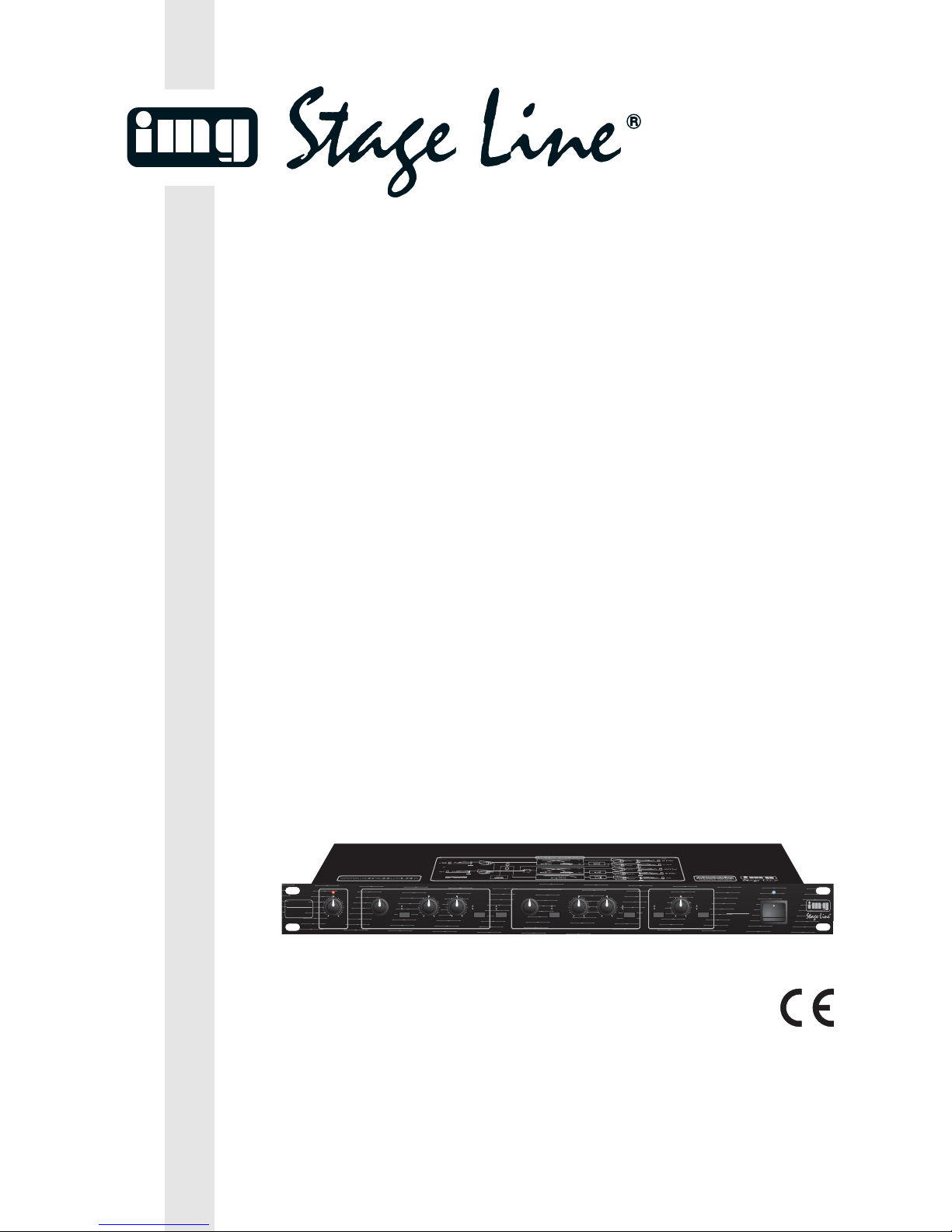
MCX-210/SW Best.-Nr. 24.4180
ELEKTRONISCHE FREQUENZWEICHE
ELECTRONIC CROSSOVER NETWORK
FILTRE DE FREQUENCES ACTIF
FILTRO ELETTRONICO
PEAK
MODE RANGE PHASE
MONO SUBWOOFER
+10–10
GAIN
dB
2-WAY
3-WAY
HI LEVEL PHASERANGECROSSOVER
FREQUENCY
80
110
150
200
270
350
1k6
1k2
900
650
500
Hz +10–10
LO LEVEL
+10–10dB dB
NORMAL
REVERSE
x1
x10
PHASERANGE
+10–10
LO LEVEL
dB
NORMAL
REVERSE
HI LEVEL
+10–10 dB
x1
x10
CHANNEL A CHANNEL B
75 Hz
120 Hz
NORMAL
REVERSE
OUTPUT
LEVEL
+10–10 dB
STATE
VARIABLE
TECHNOLOGY
LO/HI: 12dB/OCT.
SUB: 24dB/ OCT.
POWER
CROSSOVER
FREQUENCY
80
110
150
200
270
350
1k6
1k2
900
650
500
Hz
MCX-210/SW
PRO2-WAY/3-WAYACTIVE
CROSSOVER NETWORK
2
wwwwww..iimmggssttaaggeelliinnee..ccoomm
Bevor Sie einschalten ...
Wir wünschen Ihnen viel Spaß mit Ihrem neuen Gerät
von „img Stage Line“. Dabei soll Ihnen diese Bedienungsanleitung helfen alle Funktionsmöglichkeiten kennen zu lernen. Die Beachtung der Anleitung vermeidet
außerdem Fehlbedienungen und schützt Sie und Ihr
Gerät vor eventuellen Schäden durch unsachgemäßen
Gebrauch.
Den deutschen Text finden Sie auf den Seiten 4– 6.
Before you switch on ...
We wish you much pleasure with your new unit by “img
Stage Line”. With these operating instructions you will be
able to get to know all functions of the unit. By following
these instructions false operations will be avoided, and
possible damage to you and your unit due to improper
use will be prevented.
You will find the English text on the pages 4– 6.
D
A
CH
GB
Avant toute mise en service ...
Nous vous remercions d’avoir choisi un appareil “img
Stage Line” et vous souhaitons beaucoup de plaisir à
l’utiliser. Cette notice a pour objectif de vous aider à
mieux connaître les multiples facettes de l’appareil et à
vous éviter toute mauvaise manipulation.
La version française se trouve pages 7– 9.
Prima di accendere ...
Vi auguriamo buon divertimento con il Vostro nuovo apparecchio “img Stage Line”. Le istruzioni per l’uso Vi possono aiutare a conoscere tutte le possibili funzioni. E
rispettando quanto spiegato nelle istruzioni, evitate di
commettere degli errori, e così proteggete Voi stessi, ma
anche l’apparecchio, da eventuali rischi per uso improprio.
Il testo italiano lo potete trovare alle pagine 7– 9.
F
B
CH
I
Voordat u inschakelt ...
Wij wensen u veel plezier met uw nieuw toestel van “img
Stage Line”. Met behulp van bijgaande gebruiksaanwijzing kunt u alle functiemogelijkheden leren kennen. Door
deze instructies op te volgen zal een slechte werking
vermeden worden, en zal een eventueel letsel aan uzelf
en schade aan uw toestel tengevolge van onzorgvuldig
gebruik worden voorkomen.
U vindt de nederlandstalige tekst op de pagina’s 10– 12.
Antes de cualquier instalación
Tenemos de agradecerle el haber adquirido un equipo
“img Stage Line” y le deseamos un agradable uso. Este
manual quiere ayudarle a conocer las multiples facetas
de este equipo y evitar cualquier uso inadecuado.
La versión española se encuentra en las páginas 10– 12.
NL
B
E
Inden De tænder for apparatet ...
Vi ønsker Dem god fornøjelse med Deres nye “img Stage
Line” apparat. Denne brugsanvisning giver mulighed for
at lære alle apparatets funktioner at kende. Følg vejledningen for at undgå forkert betjening og for at beskytte
Dem og Deres apparat mod skade på grund af forkert
brug.
Den danske tekst finder De på side 13– 15.
Förskrift
Vi önskar dig mycket nöje med din nya enhet från “img
Stage Line”. Om du först läser instruktionerna kommer
du att få glädje av enheten under lång tid. Kunskap om
alla funktioner kan bespara dig mycket besvär med
enheten i framtiden.
Du finner den svenska texten på sidan 16– 18.
DK
S
Ennen virran kytkemistä ...
Toivomme, että uusi “img Stage Line”-laitteesi tuo sinulle
paljon iloa ja hyötyä. Tämä käyttöohje esittää sinulle
kaikki uuden laitteesi toiminnot. Seuraamalla sitä vältät
virhetoiminnot ja niistä johtuvat mahdolliset vahingot
sinulle tai laitteellesi.
Löydät suomenkieliset käyttöohjeet sivuilta 16–18.
FIN
Antes de pôr em funcionamento ...
Agradecemos-lhe por ter escolhido um aparelho “img
Stage Line”. Com estas instruções ficará habilitado a
conhecer e utilizar todas as funções desta unidade.
Seguindo-as, evita possíveis manipulações defeituosas.
A versão em idioma português pode ser encontrada nas
páginas 13– 15.
P
3
MCX-210/SW
PRO2-WAY/3-WAY ACTIVE
CROSSOVER NETWORK
123 4 5 6789 1011 1213 141516 17
➀
3-WAY
INPUT
HIHILO
MID
2-WAY STEREO
3-WAY MONO
HI
LO
LO
SUBWOOFER
230V~/50Hz
CH ACH BCHB CHA
MAINS
INPUTOUTPUT
LIFTGND
18 19 20 21 22 23 24 25
➁
GAIN
GAIN
MODE
3-WAY
2-WAY
RANGE
x1
x10
LOFILTER CHANNEL A
FREQU.
HI
LEVEL
LEVEL
LEVEL
LEVEL
SUBWOOFER FILTER
LEVEL
RANGE
75 Hz
120 H z
PHASE
PHASE
PHASE
LO CH A
LO 3-WAY
HI CH A
LO CH B
MID 3-WAY
HI CH B
HI 3-WAY
SUB
CH A
3-WAY
CH B
HI/ LO : 12dB / OCT.
SUB :24dB/OCT.
FILTER SLOPES
IN
RANGE
x1
x10
LOFILTER CHANNEL A
FREQU.
HI
PEAK
OUT
➂
Blockschaltbild
Block diagram

Bitte klappen Sie die Seite 3 heraus. Sie sehen
dann immer die beschriebenen Bedienelemente
und Anschlüsse.
1 Übersicht der Bedienelemente und
Anschlüsse
1.1 Frontseite
1 Pegelregler für die Eingänge
2 Peak-Anzeige für die Eingänge
3 Einstellregler für die Trennfrequenz
bei 2-Wege-Stereobetrieb: Low/High für Kanal A
bei 3-Wege-Monobetrieb: Low/Mid
4 Bereichsumschalter RANGE für den Regler (3)
Taste nicht gedrückt: x1 = 80 – 1 600Hz
Taste gedrückt: x10 = 800– 16000 Hz
5 Pegelregler für den Ausgang (24)
bei 2-Wege-Stereobetrieb: Low für Kanal A
bei 3-Wege-Monobetrieb: Low
6 Pegelregler für den Ausgang (23)
bei 2-Wege-Stereobetrieb: High für Kanal A
bei 3-Wege-Monobetrieb: ohne Funktion
7 Umschalter Phasenlage
bei 2-Wege-Stereobetrieb: High für Kanal A
bei 3-Wege-Monobetrieb: Mid und High
8 Betriebsarten-Umschalter
Taste nicht gedrückt: 2-Wege-Stereobetrieb
Taste gedrückt: 3-Wege-Monobetrieb
9 Einstellregler für die Trennfrequenz
bei 2-Wege-Stereobetrieb: Low/High für Kanal B
bei 3-Wege-Monobetrieb: Mid/High
10 Bereichsumschalter RANGE für den Regler (9)
Taste nicht gedrückt: x1 = 80 – 1 600Hz
Taste gedrückt: x10 = 800– 16000 Hz
11 Pegelregler für den Ausgang (22)
bei 2-Wege-Stereobetrieb: Low für Kanal B
bei 3-Wege-Monobetrieb: Mid
12 Pegelregler für den Ausgang (21)
bei 2-Wege-Stereobetrieb: High für Kanal B
bei 3-Wege-Monobetrieb: High
13 Umschalter Phasenlage
bei 2-Wege-Stereobetrieb: High für Kanal B
bei 3-Wege-Monobetrieb: High
14 Taste für die Trennfrequenz des Subwoofers
Taste nicht gedrückt: 75Hz
Taste gedrückt: 120Hz
15 Pegelregler für den Subwoofer-Ausgang (20)
16 Umschalter Phasenlage für den Subwoofer
17 Ein-/Ausschalter
1.2 Rückseite
18 Anschluss für die Stromversorgung 230V~/50Hz
19 Groundlift-Schalter zum Trennen der Signal-
masse von der Gehäusemasse, um Masseschleifen zu vermeiden
Position GND: Signal- und Gehäusemasse sind
zusammengeschaltet
Position LIFT: Signal- und Gehäusemasse sind
getrennt
20 Ausgang des Subwoofer-Kanals
21 Ausgang
bei 2-Wege-Stereobetrieb: High für Kanal B
bei 3-Wege-Monobetrieb: High
22 Ausgang
bei 2-Wege-Stereobetrieb: Low für Kanal B
bei 3-Wege-Monobetrieb: Mid
23 Ausgang
bei 2-Wege-Stereobetrieb: High für Kanal A
bei 3-Wege-Monobetrieb: dieser Ausgang wird
nicht benötigt
24 Ausgang
bei 2-Wege-Stereobetrieb: Low für Kanal A
bei 3-Wege-Monobetrieb: Low
25 Eingänge
bei 2-Wege-Stereobetrieb werden beide Eingänge benötigt
bei 3-Wege-Monobetrieb wird nur der Eingang
CH A/ 3-WAYINPUT benötigt
2 Hinweise für den sicheren Gebrauch
Dieses Gerät entspricht der Richtlinie für elektromagnetische Verträglichkeit 89/ 336/ EWG und der
Niederspannungsrichtlinie 73/23/EWG.
Beachten Sie auch unbedingt die folgenden Punkte:
●
Verwenden Sie das Gerät nur im Innenbereich.
Schützen Sie es vor Tropf- und Spritzwasser,
hoher Luftfeuchtigkeit und Hitze (zulässiger Einsatztemperaturbereich 0– 40°C).
●
Stellen Sie keine mit Flüssigkeit gefüllten Gefäße,
z.B. Trinkgläser, auf das Gerät.
●
Nehmen Sie das Gerät nicht in Betrieb bzw. ziehen Sie sofort den Netzstecker aus der Steckdose, wenn:
1. sichtbare Schäden am Gerät oder an der Netzanschlussleitung vorhanden sind,
2. nach einem Sturz oder Ähnlichem der Verdacht
auf einen Defekt besteht,
3. Funktionsstörungen auftreten.
Das Gerät in jedem Fall zur Reparatur in eine
Fachwerkstatt geben.
●
Eine beschädigte Netzanschlussleitung darf nur
durch den Hersteller oder eine autorisierte Fachwerkstatt ersetzt werden.
●
Ziehen Sie den Netzstecker nie am Kabel aus der
Steckdose, fassen Sie immer am Stecker an.
●
Für die Reinigung nur ein trockenes, weiches
Tuch verwenden, auf keinen Fall Chemikalien
oder Wasser.
●
Wird das Gerät zweckentfremdet, falsch angeschlossen bzw. bedient oder nicht fachgerecht repariert, kann keine Haftung für daraus resultie-
Achtung! Das Gerät wird mit lebensgefährlicher
Netzspannung (230 V~) versorgt. Nehmen Sie deshalb nie selbst Eingriffe am
Gerät vor. Durch unsachgemäßes Vorgehen besteht die Gefahr eines elektrischen Schlages. Außerdem erlischt
beim Öffnen des Gerätes jeglicher
Garantieanspruch.
Please unfold page 3. Then you can always see
the operating elements and connections described.
1 Operating Elements and Connections
1.1 Front panel
1 Level control for the inputs
2 Peak LED for the inputs
3 Adjusting control for the crossover frequency
with 2-way stereo operation: Low/High for chan-
nel A
with 3-way mono operation: Low/Mid
4 RANGE switch for the control (3)
Button not pressed: x1 = 80 – 1600Hz
Button pressed: x10 = 800– 16000Hz
5 Level control for the output (24)
with 2-way stereo operation: Low for channel A
with 3-way mono operation: Low
6 Level control for the output (23)
with 2-way stereo operation: High for channel A
with 3-way mono operation: no function
7 Selector switch phase condition
with 2-way stereo operation: High for channel A
with 3-way mono operation: Mid and High
8 Operating mode switch
Button not pressed: 2-way stereo operation
Button pressed: 3-way mono operation
9 Adjusting control for the crossover frequency
with 2-way stereo operation: Low/High for chan-
nel B
with 3-way mono operation: Mid/High
10 RANGE switch for the control (9)
Button not pressed: x1 = 80 – 1600Hz
Button pressed: x10 = 800– 16000Hz
11 Level control for the output (22)
with 2-way stereo operation: Low for channel B
with 3-way mono operation: Mid
12 Level control for the output (21)
with 2-way stereo operation: High for channel B
with 3-way mono operation: High
13 Selector switch phase condition
with 2-way stereo operation: High for channel B
with 3-way mono operation: High
14 Button for the crossover frequency of the sub-
woofer
Button not pressed: 75Hz
Button pressed: 120Hz
15 Level control for the subwoofer output (20)
16 Selector switch phase condition for the subwoofer
17 Power switch
1.2 Rear panel
18 Connection for the power supply 230V~/50 Hz
19 Ground lift switch to separate the signal ground
from the housing ground to avoid ground loops
Position GND: signal ground and housing
ground are combined
Position LIFT: signal ground and housing
ground are separated
20 Output of the subwoofer channel
21 Output
with 2-way stereo operation: High for channel B
with 3-way mono operation: High
22 Output
with 2-way stereo operation: Low for channel B
with 3-way mono operation: Mid
23 Output
with 2-way stereo operation: High for channel A
with 3-way mono operation: this output is not
required.
24 Output
with 2-way stereo operation: Low for channel A
with 3-way mono operation: Low
25 Inputs
with 2-way stereo operation both inputs are
necessary
with 3-way mono operation only the input CH A/
3-WAY INPUT is necessary
2 Safety Notes
This appliance corresponds to the directive for electromagnetic compatibility 89/ 336 / EEC and the low
voltage directive 73/23/EEC.
It is essential to observe the following items:
●
The unit is suitable for indoor use only. Protect it
against dripping water and splash water, high
humidity, and heat (ambient temperature range
0–40°C).
●
Do not place any vessels filled with liquid,
e.g. drinking glasses, on the unit.
●
Do not set the unit into operation, and immediately
disconnect the mains plug from the mains if
●
Do not take the unit into operation and immediately
take the mains plug out of the mains socket if:
1. damage at the unit or mains cable can be seen,
2. a defect might have occurred after a drop or
similar accident,
3. there are malfunctions.
The unit must in any case be repaired by authorized skilled personnel.
●
A damaged mains cable must only be repaired by
the manufacturer or authorized skilled personnel.
●
Never pull the mains cable to disconnect the mains
plug from the mains socket, always seize the plug.
●
Use a dry dust cloth only for cleaning, by no
means chemicals or water.
●
No guarantee claims for the unit and no liability for
any resulting personal damage or material damage will be accepted if the unit is used for other
purposes than originally intended, if it is not correctly connected, operated, or not repaired in an
expert way.
Attention!
The unit is supplied with hazardous mains
voltage (230V~). Leave servicing to skilled personnel only. Inexpert handling may
cause an electric shock hazard. Furthermore, any guarantee claim will expire if
the unit has been opened.
4
GB
D
A
CH
rende Sach- oder Personenschäden und keine
Garantie für das Gerät übernommen werden.
3 Einsatzmöglichkeiten
Mit der elektronischen Frequenzweiche MCX210/SW können Audioanlagen im aktiven 2-Wegeoder 3-Wege-Betrieb mit oder ohne zusätzlichen
Subwoofer realisiert werden. Die Weiche ist speziell
für den professionellen Einsatz auf der Bühne konzipiert sowie für den Einsatz in der Disco, für PABeschallungen und für den gesamten HiFi-Bereich
(z.B. auch als Stereo-Subwoofer-Weiche einsetzbar).
Die Frequenzweiche lässt sich vom 2-WegeStereobetrieb auf 3-Wege-Monobetrieb umschalten,
d.h. für einen 3-Wege-Stereobetrieb sind zwei
Geräte MCX-210/SW erforderlich. Die Frequenzaufteilung erfolgt mit „Active State Variable“-Filtern,
die für nahtlose Übergänge zwischen den Frequenzbereichen sorgen.
4 Aufstellmöglichkeiten
Die Frequenzweiche ist speziell für die Montage in
ein Rack (482mm/19") ausgelegt. Sie kann bei
Bedarf aber auch frei aufgestellt werden. Für den
Rackeinbau wird eine Höhe von 1HE (Höheneinheit
= 44,45mm) benötigt.
5 Gerät anschließen
Alle Anschlüsse nur bei ausgeschaltetem Gerät vornehmen bzw. verändern! Sämtliche Ein- und Ausgänge sind asymmetrisch ausgelegt.
5.1 2-Wege-Stereobetrieb
Damit die Stereokanäle nicht vertauscht werden, ist
es zu empfehlen, immer Kanal Afür den linken Kanal
zu verwenden und Kanal B für den rechten Kanal.
1) An die Eingangsbuchsen INPUT (25) die Signalquelle (z.B. Mischpult, Vorverstärker) anschießen.
2) Die Endverstärker an die folgenden Buchsen anschließen:
Low linker Kanal: CH ALO (24)
High linker Kanal: CH AHI (23)
Low rechter Kanal: CH B LO (22)
High rechter Kanal: CH B HI (21)
Subwoofer:
SUBWOOFER (20)
3) Erst zuletzt die Frequenzweiche an eine Steckdose (230V~/50 Hz) anschließen. Das Gerät
aber noch nicht einschalten. Zuerst muss eine
Grundeinstellung erfolgen, siehe Kapitel 6.1
„Grundeinstellung”.
5.2 3-Wege-Monobetrieb
1) An die Eingangsbuchse INPUT CH A/3-WAYINPUT (25) die Signalquelle (z. B. Mischpult, Vorverstärker) anschießen.
2) Die Endverstärker an die folgenden Buchsen anschließen:
Low-Kanal: CH A LO (24)
Mid-Kanal: CH B MID (22)
High-Kanal: CH B HI (21)
Subwoofer: SUBWOOFER (20)
Die Buchse CH AHI (23) wird nicht benötigt.
3) Erst zuletzt die Frequenzweiche an eine Steckdose (230V~/50 Hz) anschließen. Das Gerät
aber noch nicht einschalten. Zuerst muss eine
Grundeinstellung erfolgen, siehe Kapitel 6.1
„Grundeinstellung”.
6 Frequenzweiche einstellen
6.1 Grundeinstellung
Vor dem ersten Einschalten muss eine Grundeinstellung vorgenommen werden:
1) Mit der Taste MODE (8) die Betriebsart einstellen:
2-Wege-Stereobetrieb
➪
Taste nicht gedrückt
3-Wege-Monobetrieb
➪
Taste drücken
2) Die drei Tasten PHASE (7, 13, 16) dürfen nicht
gedrückt sein, d. h. die Phasenlage wird nicht
verändert.
3) Den Eingangspegelregler GAIN (1) und die vier
Ausgangspegelregler LO bzw. HI LEVEL (5, 6,
11, 12) in die Mittelstellung auf 0dB drehen.
4) Die Trennfrequenzen sind entsprechend der verwendeten Lautsprecher einzustellen (siehe technische Daten der Lautsprecher):
2-Wege-Stereobetrieb
Für beide Kanäle die gleiche Trennfrequenz zwi-
schen dem Low- und High-Kanal mit den Reglern
CROSSOVER FREQUENCY (3, 9) einstellen.
Den Bereich mit den Tasten RANGE (4, 10)
wählen:
x1 = 80– 1 600Hz
➪
Taste nicht gedrückt
x10 = 800– 16000Hz
➪
Taste gedrückt
3-Wege-Monobetrieb
Die Trennfrequenz zwischen dem Low- und Mid-
Kanal mit dem linken Regler CROSSOVER FREQUENCY (3) einstellen. Die dazugehörige Taste
RANGE (4) darf nicht gedrückt sein.
Die Trennfrequenz zwischen dem Mid- und
High-Kanal mit dem rechten Regler CROSSOVER FREQUENCY (9) einstellen. Den Bereich
mit der dazugehörigen Taste RANGE (10)
wählen:
x1 = 80– 1 600Hz
➪
Taste nicht gedrückt
x10 = 800– 16000Hz
➪
Taste gedrückt
5) Die Trennfrequenz für den Subwoofer mit der
Taste RANGE 75Hz/120 Hz (14) einstellen:
75Hz
➪
Taste nicht gedrückt
120Hz
➪
Taste gedrückt
Soll das Gerät endgültig aus dem Betrieb genommen werden, übergeben Sie
es zur umweltgerechten Entsorgung
einem örtlichen Recyclingbetrieb.
●
Important for U.K. Customers!
The wires in this mains lead are coloured in accordance with the following code:
blue = neutral
brown = live
As the colours of the wires in the mains lead of this
appliance may not correspond with the coloured
markings identifying the terminals in your plug,
proceed as follows:
1. The wire which is coloured blue must be connected to the terminal which is marked with the
letter N or coloured black.
2. The wire which is coloured brown must be connected to the terminal which is marked with the
letter L or coloured red.
3 Applications
With the electronic crossover network MCX-210/SW
audio systems can be used in the active 2-way or
3-way operation with or without additional subwoofer. The network has especially been designed
for professional stage as well as for disco applications, for PA systems and for the complete HiFi
range (e. g. also to be used as a stereo subwoofer
network).
The crossover network can be switched from
2-way stereo to 3-way mono operation, i. e. for a
3-way stereo operation two MCX-210/SW units are
necessary. The frequency range limiting is made
with “Active State Variable” filters which provide perfect transition crossovers between the frequency
ranges.
4 Installation
The crossover network has especially been designed for mounting in a rack (482 mm /19"). If required, it can also be used as a free standing crossover network. For the rack installation a height of
1rack space (= 44.45 mm) is necessary.
5 Connection of the Crossover Network
Only carry out or change all connections with the
network switched off! All inputs and outputs are
unbalanced.
5.1 2-way stereo operation
In order not to mix up the stereo channels, it is
recommended always to use channel A for the left
channel and channel B for the right channel.
1) Connect the signal source (e. g. mixer, preamplifier) to the input jacks INPUT (25).
2) Connect the power amplifiers to the following
jacks:
Low left channel: CH ALO (24)
High left channel: CH AHI (23)
Low right channel: CH B LO (22)
High right channel: CH B HI (21)
Subwoofer:
SUBWOOFER (20)
3) Only connect the crossover network to a mains
socket (230V~/50 Hz) as the last unit. But do not
yet switch on the network. At first a basic adjustment must be made, see chapter 6.1 “Basic
adjustment”.
5.2 3-way mono operation
1) Connect the signal source (e. g. mixer, preamplifier) to the input jack INPUT CH A/3-WAYINPUT
(25).
2) Connect the power amplifiers to the following
jacks:
Low channel: CH ALO (24)
Mid channel: CH B MID(22)
High channel: CH B HI (21)
Subwoofer:
SUBWOOFER (20)
The jack CH AHI (23) is not required.
3) Only connect the crossover network to a mains
socket (230V~/50 Hz) as the last unit. But do not
yet switch on the network. At first a basic adjustment must be made, see chapter 6.1 “Basic
adjustment”.
6Adjustment of the Crossover Network
6.1 Basic adjustment
Prior to the first switching-on a basic adjustment
must be made:
1) Adjust the operating mode with the button
MODE (8):
2-way stereo operation
➪
button not pressed
3-way mono operation
➪
button pressed
2) The three buttons PHASE (7, 13, 16) must not be
pressed, i.e. the phase condition is not changed.
3) Set the input level control GAIN (1) and the four
output level controls LO resp. HI LEVEL (5, 6, 11,
12) to mid-position 0dB.
4) Adjust the crossover frequencies according to
the speakers used (see speaker specifications):
2-way stereo operation
Adjust the same crossover frequency for both
channels between the Low and High channel
with the controls CROSSOVER FREQUENCY
(3, 9). Select the range with the buttons RANGE
(4, 10):
x1 = 80– 1 600Hz
➪
button not pressed
x10 = 800– 16000Hz
➪
button pressed
3-way mono operation
Adjust the crossover frequency between the Low
and Mid channel with the left control CROSSOVER FREQUENCY (3). The corresponding button RANGE (4) must not be pressed.
If the unit is to be put out of operation
definitively, take it to a local recycling
plant for disposal which is not harmful to
the environment.
5
GB
D
A
CH
6) Jetzt kann die komplette Audioanlage in folgender Reihenfolge (um laute Einschaltgeräusche
zu vermeiden) eingeschaltet werden:
1. Signalquelle (z.B. Mischpult, Vorverstärker)
2. Frequenzweiche mit Schalter POWER (17)
3. zum Schluss alle Verstärker
7) Tritt ein Brummen auf, das durch eine Brummschleife entsteht (z.B. Masseverbindung vom
Gehäuse über das Rack zu einem anderen
Gehäuse), den Schalter GND/ LIFT (19) auf der
Rückseite in die Position LIFT schieben. Dadurch
wird die Signalmasse von der Gehäusemasse
getrennt.
6.2 Pegel und Phasenlagen einstellen
Zur optimalen Pegeleinstellung sind ein Schallpegelmessgerät (z.B. SM-4 von MONACOR) und eine
Test-CD sehr hilfreich.
1) Ein Signal auf die Weiche geben. Mit dem Regler
GAIN (1) den Eingangspegel einstellen. Dieser
ist optimal eingestellt, wenn die LED PEAK (2)
bei den lautesten Musikpassagen kurz aufleuchtet. Leuchtet die LED länger, den Regler (1) entsprechend zurückdrehen.
2) Die Ausgangspegel mit den folgenden Reglern
untereinander angleichen:
2-Wege-Stereobetrieb
Low linker Kanal: LO LEVEL(5), CHANNELA
High linker Kanal: HI LEVEL (6), CHANNELA
Low rechter Kanal: LO LEVEL(11), CHANNEL B
High rechter Kanal:HI LEVEL (12), CHANNEL B
Subwoofer: OUTPUT LEVEL (15)
3-Wege-Monobetrieb
Low-Kanal: LO LEVEL (5), CHANNEL A
Mid-Kanal: LO LEVEL (11), CHANNEL B
High-Kanal: HI LEVEL (12),CHANNEL B
Subwoofer: OUTPUT LEVEL (15)
Der Regler HI LEVEL/ CHANNELA(6) wird nicht
benötigt.
3) Die Phasenlage der High-Kanäle, des Sub-
woofer-Kanals und bei 3-Wege-Monobetrieb
auch die des Mid-Kanals lässt sich durch Drücken
der folgenden T asten PHASE überprüfen und ggf.
korrigieren. Wird bei gedrückter T aste PHASE der
Klang verbessert, die Taste gedrückt lassen,
anderenfalls die Taste wieder lösen.
2-Wege-Stereobetrieb
High linker Kanal: PHASE (7), CHANNELA
High rechter Kanal:PHASE (13), CHANNEL B
Subwoofer: PHASE (16)
3-Wege-Monobetrieb
Mid- und High-Kanal gemeinsam: PHASE (7)
High-Kanal separat: PHASE (13)
Subwoofer: PHASE (16)
7Technische Daten
Frequenzbereich: . . . . . . . 10 –30000 Hz, -0,5dB
Trennfrequenzen
Low/High: . . . . . . . . . . 80–1600 Hz, umschalt-
bar auf 800– 16000Hz,
Subwoofer: . . . . . . . . . 75Hz umschaltbar auf
120Hz
Flankensteilheit
Low/High: . . . . . . . . . . 12dB/Okt.,
Subwoofer: . . . . . . . . . 24dB/Okt.
Klirrfaktor: . . . . . . . . . . . . < 0,05 %
Eingänge: . . . . . . . . . . . . 1V/15kΩ, asym.,
±10 dB regelbar
Ausgänge: . . . . . . . . . . . . 1 V/100Ω, asym.,
±10 dB regelbar
Störabstand: . . . . . . . . . . 80 dB
Stromversorgung: . . . . . . 230V~/50 Hz/5VA
zulässiger Einsatz-
temperaturbereich: . . . . . 0–40 °C
Abmessungen (B x H x T): 482 x 44,5 x 220mm,
1HE (Höheneinheit)
Gewicht: . . . . . . . . . . . . . . 2,5 kg
Änderungen vorbehalten.
Adjust the crossover frequency between the
Mid and High channel with the right control
CROSSOVER FREQUENCY (9). Select the
range with the button RANGE (10):
x1 = 80– 1 600Hz
➪
button not pressed
x10 = 800– 16000Hz
➪
button pressed
5) Adjust the crossover frequency for the subwoofer
with the button RANGE 75 Hz/120 Hz (14):
75Hz
➪
button not pressed
120Hz
➪
button pressed
6) Now the complete audio system can be switched
on in the following sequence (to avoid loud inrush
noise):
1. Signal source (e.g.mixer, preamplifier)
2. Crossover network with switch POWER (17)
3. Finally all amplifiers
7) If a humming occurs caused by a hum loop (e. g.
ground connection from the housing via the rack to
another housing), slide the switch GND/LIFT (19)
at the rear panel to position LIFT. Thus the signal
ground is separated from the housing ground.
6.2 Adjust level and phase conditions
For optimum level adjustment a sound level meter
(e.g. MONACOR SM-4) and a test CD are very useful.
1) Send a signal to the crossover network. Adjust
the input level with the control GAIN (1). The
optimum adjustment is made if the LED PEAK (2)
shortly lights up with the loudest music passages.
If the LED lights for a longer period of time, turn
the control (1) back correspondingly.
2) Adjust the output levels with the following controls with each other:
2-way stereo operation
Low left channel: LO LEVEL(5), CHANNELA
High left channel: HI LEVEL (6), CHANNELA
Low right channel: LO LEVEL (11),CHANNEL B
High right channel: HI LEVEL (12), CHANNEL B
Subwoofer: OUTPUT LEVEL (15)
3-way mono operation
Low channel: LO LEVEL (5),CHANNELA
Mid channel: LO LEVEL(11), CHANNEL B
High channel: HI LEVEL (12), CHANNEL B
Subwoofer: OUTPUT LEVEL (15)
The control HI LEVEL / CHANNEL A (6) is not
required.
3) The phase condition of the high channels, the
subwoofer channel and with 3-way mono operation also the phase condition of the Mid channel
can be checked and, if necessary, be corrected
by pressing the following buttons PHASE. In
case of sound improvement with button PHASE
pressed, keep the button pressed, otherwise do
not press any more.
2-way stereo operation
High left channel: PHASE (7), CHANNELA
High right channel: PHASE (13), CHANNEL B
Subwoofer: PHASE (16)
3-way mono operation
Mid and High channel in common: PHASE (7)
High channel separately: PHASE (13)
Subwoofer: PHASE (16)
7 Specifications
Frequency range: . . . . . . 10–30 000Hz, -0.5dB
Crossover frequencies
Low/High: . . . . . . . . . . 80 –1600 Hz, switch-
able to 800– 16000Hz,
subwoofer: . . . . . . . . . . 75 Hz switchable to
120Hz
Slope
Low/High: . . . . . . . . . . 12 dB/Oct.
subwoofer: . . . . . . . . . . 24 dB/Oct.
THD: . . . . . . . . . . . . . . . . < 0.05 %
Inputs: . . . . . . . . . . . . . . . 1 V/15kΩ, unbal.
±10 dB adjustable
Outputs: . . . . . . . . . . . . . . 1 V/100 Ω, unbal.
±10 dB adjustable
S/N ratio: . . . . . . . . . . . . . 80 dB
Power supply: . . . . . . . . . 230V~/50 Hz/5VA
Permissible operating
temperature range: . . . . . 0– 40 °C
Dimensions (W x H x D): . 482 x 44.5 x 220mm,
1 rack space
Weight: . . . . . . . . . . . . . . . 2.5kg
Subject to technical change.
6
GB
D
A
CH
Diese Bedienungsanleitung ist urheberrechtlich für MONACOR
®
INTERNATIONAL GmbH & Co. KG
geschützt. Eine Reproduktion für eigene kommerzielle Zwecke – auch auszugsweise – ist untersagt.
All rights reserved by MONACOR
®
INTERNATIONAL GmbH & Co. KG. No part of this instruction manual
may be reproduced in any form or by any means for any commercial use.

Ouvrez le présent livret page 3 de manière à
visualiser les éléments et branchements.
1 Eléments et branchements
1.1 Face avant
1 Potentiomètre de réglage de niveau des entrées
2 Diode témoin d’écrêtage des entrées
3 Potentiomètre de réglage de la fréquence de
coupure
mode stéréo 2 voies : Low/High pour le canal A
mode mono 3 voies : Low/Mid
4 Commutateur de plages RANGE pour le poten-
tiomètre (3)
touche non enfoncée : x1 = 80 – 1 600Hz
touche enfoncée : x10 = 800– 16000 Hz
5 Potentiomètre de réglage de niveau de la sor-
tie (24)
mode stéréo 2 voies : Low pour le canal A
mode mono 3 voies : Low
6 Potentiomètre de réglage de niveau de la sor-
tie (23)
mode stéréo 2 voies : High pour le canal A
mode mono 3 voies : sans fonction
7 Commutateur de phase
mode stéréo 2 voies : High pour le canal A
mode mono 3 voies : Mid et High
8 Sélecteur du mode de fonctionnement
touche non enfoncée : mode stéréo 2 voies
touche enfoncée : mode mono 3 voies
9 Potentiomètre de réglage de la fréquence de
coupure
mode stéréo 2 voies : Low/High pour le canal B
mode mono 3 voies : Mid/High
10 Commutateur de plages RANGE pour le poten-
tiomètre (9)
touche non enfoncée : x1 = 80 – 1 600Hz
touche enfoncée : x10 = 800– 16000 Hz
11 Potentiomètre de réglage de niveau de la sor-
tie (22)
mode stéréo 2 voies : Low pour le canal B
mode mono 3 voies : Mid
12 Potentiomètre de réglage de niveau de la sor-
tie (21)
mode stéréo 2 voies : High pour le canal B
mode mono 3 voies : High
13 Commutateur de phase
mode stéréo 2 voies : High pour le canal B
mode mono 3 voies : High
14 Sélecteur de la fréquence de coupure du sub-
woofer
touche non enfoncée : 75Hz
touche enfoncée : 120Hz
15 Potentiomètre de réglage de niveau de la sortie
du subwoofer (20)
16 Commutateur de phase pour le subwoofer
17 Interrupteur Marche/Arrêt
1.2 Face arrière
18 Branchement alimentation 230V~/50 Hz
19 Interrupteur Groundlift : séparation de la masse
du signal de la masse du boîtier pour éviter tout
bouclage de masse
position GND : les masses du signal et du boîtier
sont commutées ensemble
position LIFT : les deux masses sont séparées
20 Sortie du canal subwoofer
21 Sortie
mode stéréo 2 voies : High pour le canal B
mode mono 3 voies : High
22 Sortie
mode stéréo 2 voies : Low pour le canal B
mode mono 3 voies : Mid
23 Sortie
mode stéréo 2 voies : High pour le canal A
mode mono 3 voies : cette sortie n’est pas
utilisée
24 Sortie
mode stéréo 2 voies : Low pour le canal A
mode mono 3 voies : Low
25 Entrées
mode stéréo 2 voies : les deux entrées sont
utilisées
mode mono 3 voies : seule l’entrée CH A/
3-WAY INPUT est utilisée
2 Conseils d'utilisation
Cet appareil répond à la norme 89/ 336 / CEE relative à la compatibilité électromagnétique et à la
norme 73/23/CEE portant sur les appareils à basse
tension.
Respectez les points suivants en tout cas :
●
L’appareil n’est conçu que pour une utilisation en
intérieur. Protégez-le de l’eau d’égouttage et de
l’eau projetée, de l’humidité excessive et de la
chaleur (température d’utilisation admissible
0–40°C).
●
Ne placez pas des récipients remplis de liquide,
par exemple verres à boire, sur l’appareil.
●
Ne le faites pas fonctionner et débranchez-le
immédiatement dans les cas suivants :
1. L'appareil ou le cordon secteur présente des
dommages visibles.
2. Après une chute ..., vous avez un doute sur
l’état de l'appareil.
3. Des disfonctionnements apparaissent.
Dans tous les cas, les dommages doivent être
réparés par un technicien spécialisé.
●
Tout cordon secteur endommagé ne doit être remplacé que par le constructeur ou un technicien
habilité.
●
Ne débranchez jamais l’appareil en tirant sur le
cordon secteur ; retirez toujours le cordon secteur
en tirant la fiche.
●
Pour nettoyer l'appareil, utilisez un chiffon sec, en
aucun cas de produits chimiques ou d'eau.
●
Nous déclinons toute responsabilité en cas de
dommages matériels ou corporels résultants si
l’appareil est utilisé dans un but autre que celui
Attention ! Cet appareil est alimenté par une ten-
sion dangereuse en 230 V~. Ne touchez jamais l’intérieur de l’appareil car
en cas de mauvaise manipulation vous
pourriez subir une décharge électrique. En outre, l’ouverture de l’appareil
rend tout droit à la garantie caduque.
Vi preghiamo di aprire completamente la pagina 3. Così vedrete sempre gli elementi di
comando e i collegamenti descritti.
1 Elementi di comando e collegamenti
1.1 Pannello frontale
1 Regolatore livello per gli ingressi
2 Indicatore picchi per gli ingressi
3 Regolatore per frequenza di taglio
a 2 vie stereo: Low/High per canale A
a 3 vie mono: Low/Mid
4 Commutatore range RANGE per regolatore (3)
Tasto non premuto: x1 = 80– 1600 Hz
Tasto premuto: x10 = 800– 16000Hz
5 Regolatore livello per uscita (24)
a 2 vie stereo: Low per canale A
a 3 vie mono: Low
6 Regolatore livello per uscita (23)
a 2 vie stereo: High per canale A
a 3 vie mono: senza funzione
7 Commutatore per fase
a 2 vie stereo: High per canale A
a 3 vie mono: Mid e high
8 Commutatore modi di funzionamento
Tasto non premuto: 2 vie stereo
Tasto premuto: 3 vie mono
9 Regolatore per frequenza di taglio
a 2 vie stereo: Low/High per canale B
a 3 vie mono: Mid/High
10 Commutatore range RANGE per regolatore (9)
Tasto non premuto: x1 = 80– 1600 Hz
Tasto premuto: x10 = 800– 16000Hz
11 Regolatore livello per uscita (22)
a 2 vie stereo: Low per canale B
a 3 vie mono: Mid
12 Regolatore livello per uscita (21)
a 2 vie stereo: High per canale B
a 3 vie mono: High
13 Commutatore per fase
a 2 vie stereo: High per canale B
a 3 vie mono: High
14 Tasto per frequenza di taglio del subwoofer
Tasto non premuto: 75Hz
Tasto premuto: 120Hz
15 Regolatore livello per uscita subwoofer (20)
16 Commutatore fase per il subwoofer
17 Interruttore On/Off
1.2 Pannello posteriore
18 Collegamento alimentazione 230V~/50 Hz
19 Commutatore Groundlift per separare la massa
del segnale dalla massa del contenitore per evitare gli anelli di terra
Posizione GND: Le masse del segnale e del
contenitore sono collegate
Posizione LIFT: Le masse del segnale e del
contenitore sono separate
20 Uscita del canale del subwoofer
21 Uscita
a 2 vie stereo: High per canale B
a 3 vie mono: High
22 Uscita
a 2 vie stereo: Low per canale B
a 3 vie mono: Mid
23 Uscita
a 2 vie stereo: High per canale A
a 3 vie mono: non utilizzato
24 Uscita
a 2 vie stereo: Low per canale A
a 3 vie mono: Low
25 Ingressi
a 2 vie stereo occorrono entrambi gli ingressi
a 3 vie mono è richiesto il solo ingresso CH A /
3-WAY INPUT
2Avvisi di sicurezza
Quest’apparecchio corrisponde alla direttiva CE
89/ 336 / CEE sulla compatibilità elettromagnetica e
73/23/CEE per apparecchi a bassa tensione.
Si devono osservare assolutamente i seguenti punti:
●
Far funzionare l’apparecchio solo all’interno di
locali. Proteggerlo dall’acqua gocciolante e dagli
spruzzi d’acqua, da alta umidità dell’aria e dal
calore (temperatura d’impiego ammessa fra
0–40°C).
●
Non posare mai dei contenitori con liquidi (p. es.
bicchieri) sull’apparecchio.
●
Non mettere in funzione l’apparecchio e staccare
subito la spina rete se:
1. l'apparecchio o il cavo rete presentano dei
danni visibili;
2. dopo una caduta o dopo eventi simili sussiste il
sospetto di un difetto;
3. l'apparecchio non funziona correttamente.
Per la riparazione rivolgersi sempre ad una officina competente.
●
Il cavo rete, se danneggiato, può essere sostituito
solo dal costruttore o da un laboratorio autorizzato.
●
Staccare il cavo rete afferrando la spina, senza tirare il cavo.
●
Per la pulizia usare solo un panno morbido,
asciutto; non impiegare in nessun caso prodotti
chimici o acqua.
●
Nel caso di uso improprio, di collegamento sbagliato, di impiego scorretto o di riparazione non a
regola d’arte non si assume nessuna responsabilità per eventuali danni consequenziali a persone
Attenzione! Quest’apparecchio funziona con ten-
sione di rete di 230V~. Non intervenire mai al suo interno; la manipolazione scorretta può provocare delle
scariche pericolose. Se l’apparecchio viene aperto, cessa ogni diritto
di garanzia.
7
I
F
B
CH

pour lequel il a été conçu, s’il n’est pas correctement branché, utilisé ou n’est pas réparé par une
personne habilitée, en outre, la garantie deviendrait caduque.
3 Possibilités d’utilisation
Le filtre électronique MCX-210/SW permet de réaliser des installations Audio en fonctionnement actif
2 voies ou 3 voies avec ou sans subwoofer supplémentaire. Ce filtre est spécialement conçu pour une
utilisation professionnelle sur scène, en discothèque, sonorisation professionnelle et HiFi (il peut être
utilisé, par exemple, comme filtre subwoofer stéréo).
Le filtre peut être utilisé en mode stéréo 2 voies
ou mono 3 voies : pour un mode de fonctionnement
stéréo 3 voies, deux filtres MCX-210/SW sont nécessaires. La répartition des fréquences se fait avec
des filtres “Activate State Variable” : ils génèrent des
transitions parfaites entre les bandes de fréquence.
4 Installation
Le filtre est prévu pour un montage en rack
(482 mm/19") et peut également être directement
posé sur une table ; pour un montage en rack,
1unité (1 U = 44,45mm) est nécessaire.
5 Branchements
Attention ! Tout branchement ou toute modification
de branchement ne doit s’effectuer que lorsque l’appareil est débranché ! Toutes les entrées et sorties
sont asymétriques.
5.1 Fonctionnement stéréo 2 voies
Afin de ne pas intervertir les canaux stéréo, nous
vous recommandons d’utiliser toujours le canal A
pour le canal gauche et le canal B pour le canal
droit.
1) Reliez la source aux entrées INPUT (25) (par
exemple, table de mixage, préamplificateur).
2) Reliez les amplificateurs comme suit :
Low canal gauche : CH ALO (24)
High canal gauche : CH A HI (23)
Low canal droit : CH B LO (22)
High canal droit : CH B HI (21)
Subwoofer :
SUBWOOFER (20)
3) Reliez maintenant le filtre à la prise secteur
230 V~/ 50 Hz ; avant d’allumer l’appareil, vous
devez effectuer les réglages de base : voir chapitre 6.1.
5.2 Fonctionnement mono 3 voies
1) Reliez la source (par exemple table de mixage,
préamplificateur) à l’entrée INPUT CH A/ 3-WAY
INPUT (25).
2) Reliez les amplificateurs aux prises comme suit :
Low canal : CH A LO (24)
Mid canal : CH B MID (22)
High canal : CH B HI (21)
Subwoofer :
SUBWOOFER (20)
La prise CH AHI (23) n’est pas utilisée.
3) Reliez maintenant le filtre à une prise secteur
230 V~ / 50 Hz et effectuez les réglages de base
avant de l’allumer (voir chapitre 6.1).
6 Réglages du filtre
6.1 Réglages de base
Avant d’allumer votre filtre pour sa première utilisation, procédez comme suit :
1) Réglez le mode de fonctionnement avec la touche MODE (8) :
mode stéréo 2 voies
➪
touche non enfoncée
mode mono 3 voies
➪
touche enfoncée
2) Les trois touches PHASE (7, 13, 16) ne doivent
pas être enfoncées : la phase ne doit pas être
modifiée.
3) Mettez le potentiomètre GAIN (1) et les quatre
potentiomètres de réglage de niveau de sortie
LO / HI LEVEL (5, 6,11, 12) sur la position médiane 0dB.
4) Réglez les fréquences de coupure selon les
haut-parleurs utilisés (reportez-vous aux caractéristiques des haut-parleurs) :
Mode stéréo 2 voies
Réglez la même fréquence de coupure pour
les deux canaux entre le canal Low et High avec
les potentiomètres CROSSOVER FREQUENCY
(3, 9) ; sélectionnez la plage avec les touches
RANGE (4, 10) :
x1 = 80– 1 600Hz
➪
touche non enfoncée
x10 = 800– 16000Hz
➪
touche enfoncée
Mode mono 3 voies
Réglez la fréquence de coupure entre le canal
Low et Mid avec le potentiomètre gauche CROSSOVER FREQUENCY (3) ; la touche correspondante RANGE (4) ne doit pas être enfoncée.
Réglez la fréquence de coupure entre le canal
Mid et High avec le potentiomètre droit CROSSOVER FREQUENCY (9) ; sélectionnez la plage
avec la touche RANGE (10) correspondante :
x1 = 80– 1 600Hz
➪
touche non enfoncée
x10 = 800– 16000Hz
➪
touche enfoncée
Lorsque l’appareil est définitivement retiré du marché, vous devez le déposer
dans une usine de recyclage de proximité pour contribuer à son élimination
non polluante.
o a cose e non si assume nessuna garanzia per
l’apparecchio.
3 Possibilità d'impiego
Con il filtro elettronico MCX-210/SW si possono
realizzare impianti audio attivi a 2 o 3 vie, con o
senza subwoofer supplementare. Il filtro è previsto
per l'uso professionale, quindi per musicisti, per discoteca, per sonorizzazioni PA e per tutto il settore
hifi (p.es. come filtro stereo subwoofer).
Esiste la possibilità di commutazione fra funzionamento stereo a 2 e funzionamento mono a 3 vie.
Nel caso di funzionamento stereo a 3 vie occorrono
due MCX-210/SW. La suddivisione delle frequenze
è con filtri “Active State Variable” che permettono dei
passaggi senza interruzioni fra i vari range di frequenza.
4 Possibilità di collocazione
Il filtro è previsto per il montaggio in un rack
(482mm/19"). Se necessario, può essere collocato
anche liberamente. Il montaggio in rack richiede
1 unità di altezza (= 44,45 mm).
5 Collegamento
Eseguire tutti i collegamenti e cambiamenti solo con
l'apparecchio spento! Gli ingressi e le uscite sono
asimmetriche.
5.1 Funzionamento stereo a 2 vie
Per non scambiare i canali stereo si consiglia di
usare per il canale di sinistra sempre il canale A, e
per quello di destro il canale B.
1) Collegare la sorgente (p. es. mixer, preamplificatore) con le prese d'ingresso INPUT (25).
2) Collegare gli amplificatori finali con le seguenti
prese:
Low canale di sinistra: CH ALO (24)
High canale di sinistra: CH A HI (23)
Low canale di destra: CH B LO (22)
High canale di destra: CH B HI (21)
Subwoofer: SUBWOOFER (20)
3) Alle fine collegare il filtro con l'alimentazione rete
(230 V~/ 50 Hz) senza accendere l'apparecchio.
Prima occorre eseguire una regolazione base;
vedere capitolo 6.1 “Regolazione base”.
5.2 Funzionamento mono a 3 vie
1) Collegare la sorgente (p. es. mixer, preamplificatore) con la prese d'ingresso INPUT CH A/
3-WAY INPUT (25).
2) Collegare gli amplificatori finali con le seguenti
prese:
Canale Low: CH ALO (24)
Canale Mid: CH B MID (22)
Canale High: CH B HI (21)
Subwoofer: SUBWOOFER (20)
La presa CH AHI (23) non viene utilizzata.
3) Alle fine collegare il filtro con l'alimentazione rete
(230 V~/ 50 Hz) senza accendere l'apparecchio.
Prima occorre eseguire una regolazione base;
vedere capitolo 6.1 2 “Regolazione base”.
6 Regolazione del filtro
6.1 Regolazione base
Prima della prima accensione occorre eseguire una
regolazione base:
1) Impostare il modo di funzionamento con il tasto
MODE (8):
2 vie stereo
➪
tasto non premuto
3 vie mono
➪
premere tasto
2) I tre tasti PHASE (7, 13, 16) non devono essere
premuti, le fasi cioè non vengono modificate.
3) Portare in posizione centrale a 0 dB il regolatore
del livello d'ingresso GAIN (1) nonché i quattro
regolatori d'uscita LO e HI LEVEL (5, 6, 11, 12).
4) Impostare le frequenze di taglio secondo gli altoparlanti impiegati (vedere i dati tecnici degli altoparlanti):
Funzionamento stereo a 2 vie
Con i regolatori CROSSOVER FREQUENCY (3,
9) impostare per entrambi i canali la stessa frequenza di taglio fra i canali Low e High. Selezionare il range con i tasti RANGE (4, 10):
x1 = 80– 1 600Hz
➪
tasto non premuto
x10 = 800– 16000Hz
➪
tasto premuto.
Funzionamento mono a 3 vie
Con il regolatore di sinistra CROSSOVER FRE-
QUENCY (3) impostare la frequenza di taglio fra
il canale Low e High. Il tasto RANGE (4) non
dev'essere premuto.
Con il regolatore di destra CROSSOVER
FREQUENCY (9) impostare la frequenza di taglio fra il canale Mid e High. Selezionare il range
con il relativo tasto RANGE (10):
x1 = 80– 1 600Hz
➪
tasto non premuto
x10 = 800– 16000Hz
➪
tasto premuto.
5) Impostare la frequenza di taglio per il subwoofer
con il tasto RANGE 75Hz/120 Hz (14).
75Hz
➪
tasto non premuto
120Hz
➪
tasto premuto.
6) A questo punto si può accendere l'intero impianto
audio nel seguente ordine (per evitare rumori di
commutazione):
1. sorgente (p.es. mixer, preamplificatore)
2. filtro con l'interruttore POWER (17)
3. alla fine tutti gli amplificatori.
7) Nel caso di presenza di un ronzio in seguito ad
un anello di terra (p.es. collegamento della
massa del contenitore con il contenitore di un
altro apparecchio attraverso il rack), spostare il
commutatore GND/ LIFT (19) sul retro in posizione LIFT. In questo modo si separa la massa
del segnale dalla massa del contenitore.
Se si desidera eliminare l’apparecchio
definitivamente, consegnarlo per lo smaltimento ad un’istituzione locale per il riciclaggio.
8
I
F
B
CH

5) Réglez la fréquence de coupure pour le subwoofer
avec la touche RANGE 75Hz/120 Hz (14) :
75Hz
➪
touche non enfoncée
120Hz
➪
touche enfoncée
6) Vous pouvez maintenant allumer l’ensemble de
votre système audio dans l’ordre suivant afin
d’éviter les bruits forts au démarrage :
1. source (table de mixage, préamplificateur)
2.
filtre avec l’interrupteur POWER (17)
3. tous les amplis
7) En cas de ronflements, causés par un bouclage
de masse (p.ex. liaison via le rack entre le boîtier
du filtre et un autre boîtier), mettez l’interrupteur
GND/ LIFT (19) situé sur la face arrière, sur la
position LIFT : la masse du signal sera séparée
de celle du boîtier.
6.2 Réglages des niveaux et de la phase
Pour un réglage optimal des niveaux, l’utilisation
d’un sonomètre (p. ex. MONACOR SM-4) et d’un
CD test est conseillée.
1) Envoyez un signal au filtre ; réglez le niveau
d’entrée avec le potentiomètre GAIN (1) : son
réglage est optimal lorsque la diode PEAK (2)
s’allume brièvement pour les passages de musique les plus forts. Si la diode brille plus longtemps, tournez le potentiomètre (1) dans l’autre
sens.
2) Adaptez les niveaux de sortie avec les réglages
suivants :
Mode stéréo 2 voies
Low canal gauche LO LEVEL (5), CHANNEL A
High canal gauche HI LEVEL (6), CHANNEL A
Low canal droit LO LEVEL(11), CHANNEL B
High canal droit HI LEVEL (12), CHANNEL B
Subwoofer OUTPUT LEVEL (15)
Mode mono 3 voies
Low canal LO LEVEL(5), CHANNELA
Mid canal LO LEVEL (11), CHANNEL B
High canal HI LEVEL (12), CHANNEL B
Subwoofer OUTPUT LEVEL (15)
Le potentiomètre HI LEVEL/ CHANNEL A (6)
n’est pas utilisé.
3) En enfonçant la touche PHASE, vous pouvez
vérifier et le cas échéant modifier la phase des
canaux High, du canal subwoofer et en mode
mono 3 voies celle du canal Mid. Si, lorsque la
touche PHASE est enfoncée, le son est meilleur,
maintenez-la enfoncée ; sinon, relâchez-la.
Mode stéréo 2 voies
High canal gauche PHASE (7), CHANNELA
High canal droit PHASE (13),CHANNEL B
Subwoofer PHASE (16)
Mode mono 3 voies
Canaux Mid et High ensemble PHASE (7)
Canal High séparé PHASE (13)
Subwoofer PHASE (16)
7 Caractéristiques techniques
Bande passante : . . . . . . . 10 –30000 Hz, -0,5dB
Fréquences de coupure
Low/High : . . . . . . . . . . 80– 1600 Hz, commuta-
ble sur 800– 16000Hz
subwoofer : . . . . . . . . . 75 Hz commutable sur
120Hz
Pente
Low/High : . . . . . . . . . . 12dB/oct.
subwoofer : . . . . . . . . . 24 dB/oct.
Taux de distorsion : . . . . . < 0,05%
Entrées : . . . . . . . . . . . . . 1 V/15kΩ, asymétrique
±10 dB réglable
Sorties : . . . . . . . . . . . . . . 1 V/100Ω, asymétri-
ques
±10 dB, réglable
Rapport signal/bruit : . . . . 80dB
Alimentation : . . . . . . . . . . 230V~/50 Hz/5VA
Température autroisée
de fonctionnement : . . . . . 0 – 40°C
Dimensions (L x H x P) : . 482 x 44,5 x 220mm,
1U
Poids : . . . . . . . . . . . . . . . 2,5kg
Tout droit de modification réservé.
6.2 Regolazione del livello e delle fasi
Per regolare il livello in modo ottimale sono molto
utili un misuratore del livello sonoro (p.es.
MONACOR SM-4) ed un CD per test.
1) Applicare al filtro un segnale. Regolare il livello
d'ingresso con il regolatore GAIN (1). La regolazione è ottimale se il led PEAK (2) si accende
brevemente con le parti più forti. Se il led si
accende a lungo, abbassare il regolatore (1).
2) Adattare il livello d'uscita con i seguenti regolatori:
Funzionamento stereo a 2 vie
Low canale di sinistra: LO LEVEL(5), CHANNEL A
High canale di sinistra: HI LEVEL (6), CHANNEL A
Low canale di destra: LO LEVEL(11), CHANNEL B
High canale di destra: HI LEVEL (12), CHANNEL B
Subwoofer: OUTPUT LEVEL (15)
Funzionamento mono a 3 vie
Canale Low: LO LEVEL(5), CHANNEL A
Canale Mid: LO LEVEL(11), CHANNEL B
Canale High: HI LEVEL (12), CHANNEL B
Subwoofer: OUTPUT LEVEL (15)
Il regolatore HI LEVEL/ CHANNEL A (6) non
viene utilizzato.
3) Le fasi dei canali high, del subwoofer e nel caso
di funzionamento mono a 3 vie anche quelle del
canale mid possono essere controllate ed eventualmente corrette premendo i seguenti tasti
PHASE. Se con il tasto premuto, il suono migliora, lasciare il tasto premuto, altrimenti liberarlo.
Funzionamento stereo a 2 vie
High canale di sinistra: PHASE (7), CHANNEL A
High canale di destra: PHASE (13), CHANNEL B
Subwoofer: PHASE (16)
Funzionamento mono a 3 vie
Canale Mid e Low insieme: PHASE (7)
Canale High separato: PHASE (13)
Subwoofer: PHASE (16)
7 Dati tecnici
Banda passante: . . . . . . . 10– 30000Hz,
-
0,5dB
Frequenze di taglio
Low/High: . . . . . . . . . . 80 –1600 Hz, commuta-
bile a 800– 16000Hz
subwoofer: . . . . . . . . . . 75 Hz commutabile a
120Hz
Pendenza
Low/High: . . . . . . . . . . 12 dB/oct.
subwoofer: . . . . . . . . . . 24 dB/oct.
Fattore di distorsione: . . . < 0,05%
Ingressi: . . . . . . . . . . . . . . 1 V/15 kΩ, asimm.
±10 dB regolabile
Uscite: . . . . . . . . . . . . . . . 1V/100 Ω, asimm.
±10 dB regolabile
Rapporto R/S: . . . . . . . . . 80 dB
Alimentazione: . . . . . . . . . 230 V~/50Hz/5 VA
Temperatura ammessa: . . 0–40 °C
Dimensioni (l x h x p): . . . 482 x 44,5 x 220mm,
1 unità di altezza
Peso: . . . . . . . . . . . . . . . . 2,5 kg
Con riserva di modifiche tecniche.
9
I
F
B
CH
Notice d’utilisation protégée par le copyright de MONACOR
®
INTERNATIONAL GmbH & Co. KG. Toute
reproduction même partielle à des fins commerciales est interdite.
La MONACOR
®
INTERNATIONALGmbH & Co. KG si riserva ogni diritto di elaborazione in qualsiasi forma
delle presenti istruzioni per l’uso. La riproduzione – anche parziale – per propri scopi commerciali è vietata.

Vouw bladzijde 3 helemaal open, zodat u steeds
een overzicht hebt van de bedieningselementen
en de aansluitingen.
1 Overzicht van de bedieningselemen-
ten en de aansluitingen
1.1 Frontpaneel
1 Niveauregelaar voor de ingangen
2 Peak-aanduiding voor de ingangen
3 Regelaar voor instelling van de scheidingsfre-
quentie
bij 2-weg-stereowerking: Low/High voor kanaal A
bij 3-weg-monowerking: Low/Mid
4 Keuzeschakelaar bandbreedte RANGE voor de
regelaar (3)
Toets niet ingedrukt: x1 = 80– 1600 Hz
Toets ingedrukt: x10 = 800– 16 000Hz
5 Niveauregelaar voor de uitgang (24)
bij 2-weg-stereowerking: Low voor kanaal A
bij 3-weg-monowerking: Low
6 Niveauregelaar voor de uitgang (23)
bij 2-weg-stereowerking: High voor kanaal A
bij 3-weg-monowerking: zonder functie
7 Keuzeschakelaar fase-instelling
bij 2-weg-stereowerking: High voor kanaal A
bij 3-weg-monowerking: Mid en High
8 Keuzeschakelaar bedrijfsmodus
Toets niet ingedrukt: 2-weg-stereowerking
Toets ingedrukt: 3-weg-monowerking
9 Regelaar voor instelling van de scheidingsfre-
quentie
bij 2-weg-stereowerking: Low/High voor kanaal B
bij 3-weg-monowerking: Low/Mid
10 Keuzeschakelaar bandbreedte RANGE voor de
regelaar (9)
Toets niet ingedrukt: x1 = 80– 1600 Hz
Toets ingedrukt: x10 = 800– 16 000Hz
11 Niveauregelaar voor de uitgang (22)
bij 2-weg-stereowerking: Low voor kanaal B
bij 3-weg-monowerking: Mid
12 Niveauregelaar voor de uitgang (21)
bij 2-weg-stereowerking: High voor kanaal B
bij 3-weg-monowerking: High
13 Keuzeschakelaar fase-instelling
bij 2-weg-stereowerking: High voor kanaal B
bij 3-weg-monowerking: High
14 Toets voor de scheidingsfrequentie van de sub-
woofer
Toets niet ingedrukt: 75 Hz
Toets ingedrukt: 120Hz
15 Niveauregelaar voor de subwoofer-uitgang (20)
16 Keuzeschakelaar fase-instelling voor de sub-
woofer
17 POWER-schakelaar
1.2 Achterzijde van het toestel
18 Aansluiting voor voedingsspanning 230 V~/50 Hz
19 Grondlift-schakelaar voor de scheiding van sig-
naalmassa en behuizings-massa, om aardlussen te vermijden
Stand GND: Signaalmassa en behuizing-
massa zijn met elkaar verbonden
Stand LIFT: Signaalmassa en behuizing-
massa zijn gescheiden
20 Uitgang van het subwoofer-kanaal
21 Uitgang
bij 2-weg-stereowerking: High voor kanaal B
bij 3-weg-monowerking: High
22 Uitgang
bij 2-weg-stereowerking: Low voor kanaal B
bij 3-weg-monowerking: Mid
23 Uitgang
bij 2-weg-stereowerking: High voor kanaal A
bij 3-weg-monowerking: Deze uitgang wordt niet
gebruikt
24 Uitgang
bij 2-weg-stereowerking: Low voor kanaal A
bij 3-weg-monowerking: Low
25 Ingangen
bij 2-weg-stereowerking worden beide ingangen
gebruikt
bij 3-weg-monowerking wordt slechts één uitgang CHA/3-WAY INPUT gebruikt
2Veiligheidsvoorschriften
Dit toestel is in overeenstemming met de EU-richtlijn
89/ 336/ EEG voor elektromagnetische compatibiliteit en 73/23/EEG voor toestellen op laagspanning.
Let eveneens op het volgende:
●
Het toestel is enkel geschikt voor gebruik binnenshuis. Vermijd druip- en spatwater, uitzonderlijk warme plaatsen en plaatsen met een hoge
vochtigheid (toegestaan omgevingstemperatuurbereik: 0– 40°C).
●
Plaats geen bekers met vloeistof zoals drinkglazen op het toestel.
●
Schakel het toestel niet in resp. trek onmiddellijk
de stekker uit het stopcontact, wanneer:
1. het netsnoer zichtbaar beschadigd is.
2. er een defect zou kunnen optreden nadat het
toestel bijvoorbeeld gevallen is.
3. het toestel slecht functioneert.
Het apparaat moet in elk geval hersteld worden
door een gekwalificeerd vakman.
●
Een defect netsnoer mag enkel door de fabrikant
of door een gekwalificeerd persoon hersteld worden.
●
Trek de stekker nooit met het snoer uit het stopcontact, maar met de stekker zelf.
●
Verwijder het stof met een droge doek. Gebruik
zeker geen chemicaliën of water.
Opgelet! De netspanning (230 V~ /50 Hz) van het
toestel is levensgevaarlijk. Open het toestel niet, want door onzorgvuldige ingrepen loopt u het risico van een elektrische
schok. Bovendien vervalt elke garantie bij
het eigenhandig openen van het toestel.
Si desea ver los elementos operativos y las
conexiones descritas referirse a la página 3.
1 Elementos de control y conexiones
1.1 Panel frontal
1 Control nivel de entradas
2 LED indicador picos de entrada
3 Control ajuste de frecuencias del crossover
Con 2 vías estéreo: graves/agudos para canal A
Con 3 vías mono: graves/medios
4 Interruptor rango RANGE para control (3)
Botón no apretado: x1 = 80– 1600Hz
Botón apretado: x10 = 800– 16000 Hz
5 Control nivel de salida (24)
Con 2 vías estéreo: graves para canal A
Con 3 vías mono: graves
6 Control nivel de salida (23)
Con 2 vías estéreo: agudos para canal A
Con 3 vías mono: sin función
7 Selector de fase
Con 2 vías estéreo: agudos para canal A
Con 3 vías mono: medios y agudos
8 Interruptor modo de operación
Botón no apretado: 2 vías estéreo
Botón apretado: 3 vías mono
9 Control de ajuste para frecuencias del crossover
Con 2 vías estéreo: graves/agudos para canal B
Con 3 vías mono: medios/agudos
10 Interruptor de rango RANGE para control (9)
Botón no apretado: x1 = 80– 1600Hz
Botón apretado: x10 = 800– 16000 Hz
11 Control nivel de salida (22)
2 vías estéreo: graves para canal B
3 vías mono: medios
12 Control nivel de salida (21)
2 vías estéreo: agudos para canal B
3 vías mono: agudos
13 Selector de fase
2 vías estéreo: agudos para canal B
3 vías mono: agudos
14 Corte de frecuencia entre del subwoofer
Botón no apretado: 75 Hz
Botón apretado: 120Hz
15 Control nivel de salida del subwoofer (20)
16 Selector de fase del subwoofer
17 Interruptor ON/OFF
1.2 Panel posterior
18 Conexión alimentación 230V~/50 Hz
19 Interruptor Groundlift para separar la señal de
masa de la del chasis para evitar realimentaciones
Posición GND: Las dos masas van combinadas
Posición LIFT: Separadas
20 Salida canal subwoofer
21 Salida
2 vías estéreo: agudos para canal B
3 vías mono: agudos
22 Salida
2 vías estéreo: graves para canal B
3 vías mono: medios
23 Salida
2 vías estéreo: agudos para canal A
3 vías mono: no necesaria
24 Salida
2 vías estéreo: graves para canal A
3 vías mono: graves
25 Entradas
Con 2 vías estéreo necesitará ambas entradas
Con 3 vías mono solo es necesaria la entrada
CHA/3-WAY INPUT
2 Consejos de uso
Este aparato cumple la norma 89/336/CEE relativa
a la compatibilidad electromagnética y a la norma
73/23/CEE sobre aparatos de baja tensión.
Respetar en todo caso los siguientes puntos:
●
El aparato sólo se puede usar en interior. Protegerlo de la agua de goteo y de la agua proyectada, de la humedad elevada y del calor (temperatura de utilización autorizada 0– 40°C).
●
No poner recipientes llenados de líquido, p. ej.
vasos, sobre el aparato.
●
No conectarlo y desconectarlo de inmediato de la
red ya que:
1. el aparato o el cable de red presenta desperfectos,
2. después de una caída o accidente parecido, el
aparato pueda estar dañado,
3. aparecen disfunciones.
Llamar a un técnico habilitado para efectuar las
reparaciones.
●
El cable de conexión a red solo puede ser cambiado por el fabricante.
●
No desconecte nunca el aparato tirando el cable
de red, sujételo siempre por la toma.
●
Para su limpieza usar un trapo seco, sin productos químicos ni agua.
●
Rechazamos todo tipo de responsabilidad en caso
de daños materiales o corporales resultandos si el
aparato se utiliza en otro fin para el cual ha sido
¡Atención! Está alimentado por una tensión peli-
grosa de 230 V~. No tocar nunca el
interior del aparato ya que en caso de
una mala manipulación podría sufrir
una descarga eléctrica mortal. Igualmente, la abertura del aparato anula
cualquier tipo de garantía.
10
E
NL
B

●
In geval van ongeoorloofd of verkeerd gebruik, verkeerde aansluiting, foutieve bediening of van herstelling door een niet-gekwalificeerd persoon vervalt
de garantie en de verantwoordelijkheid voor hieruit
resulterende materiële of lichamelijke schade.
3Toepassingen
Met behulp van het elektronische scheidingsfilter
MCX-210/SW kunnen audio-installaties met actieve
2-weg- of 3-weg-werking met of zonder bijkomende
subwoofer gerealiseerd worden. Het filter is speciaal
ontworpen voor professioneel gebruik op het
podium evenals voor het gebruik in de discotheek,
voor PA-installaties en voor het volledige HiFi-bereik
(bv. ook als stereo-subwooferfilter bruikbaar).
Het scheidingsfilter kan van 2-weg-stereowerking
naar 3-weg-monowerking geschakeld worden,
d.w.z. dat er voor 3-weg-monowerking twee scheidingsfilters MCX-210/ SW nodig zijn. De indeling in
frequentiebereiken gebeurt met de “Active State
Variable”-filters, die voor een naadloze overgang van
het ene naar het andere frequentiebereik zorgen.
4 Installatie van het filter
Het frequentiefilter is voorzien voor montage in een
19"-rack (482mm), maar kan ook als vrijstaand
tafelmodel worden gebruikt. Voor montage in een
rack is 1 rack-eenheid (= 44,45mm) nodig.
5 Aansluiting van het filter
Sluit de in- en uitgangen enkel aan resp. verander
ze, wanneer het toestel uitgeschakeld is. Alle in- en
uitgangen zijn ongebalanceerd.
5.1 2-weg-stereowerking
Om de stereokanalen niet met elkaar te verwisselen, is het aangeraden om kanaal A steeds als het
linker kanaal en kanaal B steeds als het rechter
kanaal te gebruiken.
1) Sluit de signaalbron (bv. mengpaneel, voorversterker) aan op de ingangsconnectoren INPUT (25).
2) Sluit de eindversterker op de volgende connectoren aan:
Low linker kanaal: CH ALO (24)
High linker kanaal: CH AHI (23)
Low rechter kanaal: CH B LO (22)
High rechter kanaal: CH B HI (21)
Subwoofer: SUBWOOFER (20)
3) Verbind het frequentiefilter pas als laatste met
een stopcontact (230 V~/50Hz), maar schakel
het filter nog niet in. Eerst dient de basisinstelling
te gebeuren, zie hoofdstuk 6.1 “Basisinstelling”.
5.2 3-weg-monowerking
1) Sluit de signaalbronnen (bv. mengpaneel, voorversterker) op de ingangsconnectoren INPUT
CH A/3-WAY INPUT (25) aan.
2) Sluit de eindversterker op de volgende connectoren aan:
Low-kanaal: CH ALO (24)
Mid-kanaal: CH B MID (22)
High-kanaal: CH B HI (21)
Subwoofer: SUBWOOFER (20)
De connector CH AHI (23) wordt niet gebruikt.
3) Verbind het frequentiefilter pas als laatste met
een stopcontact (230 V~/50Hz), maar schakel
het filter nog niet in. Eerst dient de basisinstelling
te gebeuren, zie hoofdstuk 6.1 “Basisinstelling”.
6 Instelling van het frequentiefilter
6.1 Basisinstelling
Alvorens het filter in gebruik te nemen, dient er een
basisinstelling uitgevoerd te worden:
1) Stel met de MODE-toets (8) de bedrijfsmodus in:
2-weg-stereowerking
➪
toets niet ingedrukt
3-weg-monowerking
➪
toets ingedrukt
2) De drie PHASE-toetsen (7, 13, 16) mogen niet ingedrukt zijn, d.w.z. de fase-instelling wordt niet
gewijzigd.
3) Plaats de regelaar GAIN (1) voor het ingangsniveau en de vier regelaars LO resp. HI LEVEL
(5, 6, 11, 12) voor het uitgangsniveau in de middelste stand (0dB).
4) De scheidingsfrequenties moeten overeenkomstig de gebruikte luidsprekers ingesteld worden
(zie technische gegevens van de luidsprekers):
2-weg-stereowerking
Stel met behulp van de regelaars CROSSOVER
FREQUENCY (3, 9) voor beide kanalen dezelfde
scheidingsfrequentie tussen Low- en High-kanaal
in. Stel met behulp van de RANGE-toetsen (4, 10)
het bereik in:
x1 = 80– 1 600Hz
➪
toets niet ingedrukt
x10 = 800– 16000Hz
➪
toets ingedrukt
3-weg-monowerking
Stel met behulp van de linker regelaar CROSS-
OVER FREQUENCY (3) de scheidingsfrequentie
tussen het Low- en Mid-kanaal in. De overeenkomstige RANGE-toets (4) mag niet ingedrukt
zijn.
Stel met behulp van de rechter regelaar
CROSSOVER FREQUENCY (9) de scheidingsfrequentie tussen het Mid- en High-kanaal in. Stel
met behulp van de overeenkomstige RANGEtoets (10) het bereik in. De overeenkomstige
RANGE-toets (4) mag niet ingedrukt zijn:
x1 = 80– 1 600Hz
➪
toets niet ingedrukt
x10 = 800– 16000Hz
➪
toets ingedrukt
Wanneer het toestel definitief uit bedrijf
genomen wordt, bezorg het dan voor
milieuvriendelijke verwerking aan een
plaatselijk recyclagebedrijf.
fabricado, si no está correctamente conectado, utilizado o reparado por una persona habilitada.
3 Aplicaciones
Con el crossover MCX-210/SW los sistemas de
audio pueden ser utilizados como 2 o 3 vías activas
con o sin subwoofer adicional. El filtro ha sido especialmente diseñado para aplicaciones profesionales
en directo, discotecas, PAo como complemento en
HiFi (p.ej. puede también estar utilizado como filtro
estéreo subwoofer).
Este crossover es conmutable 2 vías estéreo a
3 vías mono. Para 3 vías estéreo necesitará dos
unidades de MCX-210/SW. Son usados filtros
“Active State Variable” que procuran transiciones
perfectas entre los rangos de frecuencias.
4 Instalación
El crossover está previsto para un montaje en rack
(482mm/19"), puede ser igualmente dejado directamente encima de una mesa; 1 U (= 44,45 mm) es
necesaria para una instalación en rack.
5 Conexión
¡Para desconectar o variar conexiones asegúrese
de que el crossover esté parado! T odas las entradas
y salidas son no balanceadas.
5.1 2 vías estéreo
Para no mezclar los canales estéreo, se recomienda siempre utilizar el canal A para los canales
de la izquierda y canal B para los de la derecha.
1) Conectar la fuente de señal (p. ej. mezclador,
preamplificador) a la entrada INPUT (25).
2) Conectar los amplificadores de potencia de la siguiente forma:
Canal izquierdo bajos: CH ALO (24)
Canal izquierdo agudos: CH A HI (23)
Canal derecho bajos: CH B LO (22)
Canal derecho agudos: CH B HI (21)
Subwoofer: SUBWOOFER (20)
3) Conectar el crossover a la red 230 V~/ 50 Hz en
último lugar. No poner aún en marcha la unidad,
antes de efectuar un ajuste básico (ver cap. 6.1).
5.2 3 vías mono
1) Conectar la fuente de señal a la entrada INPUT
CH A /3-WAY INPUT (25) [p. ej. mezclador, preamplificador].
2) Conectar los amplificadores de potencia de la siguiente forma:
Canal graves: CH ALO (24)
Canal medios: CH B MID (22)
Canal agudos: CH B HI (21)
Subwoofer: SUBWOOFER (20)
La salida CH AHI (23) no es necesario.
3) Conectar el crossover a la red 230 V~/ 50 Hz en
último lugar. No poner aún en marcha la unidad,
antes de efectuar un ajuste básico (ver cap. 6.1).
6 Ajuste del filtro activo
6.1 Ajuste básico
1) Ajustar el modo de función con el selector
MODE (8):
2 vías estéreo
➪
botón no apretado
3 vías mono
➪
botón apretado
2) Los tres botones PHASE (7, 13, 16) no deben
estar apretados, es decir la fase no está cambiada.
3) Colocar la entrada de control de nivel GAIN (1) y
los cuatro controles de salida LO HI LEVEL (5, 6,
11, 12) en posición media 0dB.
4) Ajustar las frecuencias de corte según el tipo de
altavoces que se utilicen (ver especificaciones
de los altavoces):
2 vías estéreo
Ajustar la frecuencia para ambos canales igual
entre el canal de graves y agudos con los controles CROSSOVER FREQUENCY (3, 9). Seleccionar el rango con los botones RANGE (4, 10):
x1 = 80– 1 600Hz
➪
botón no apretado
x10 = 800– 16000Hz
➪
botón apretado
3 vías mono
Ajustar la frecuencia entre los canales de graves
y medios con el control CROSSOVER FREQUENCY (3). El botón correspondiente a
RANGE (4) no debe estar apretado.
Ajustar la frecuencia entre los canales de medios y agudos con el control de la derecha
CROSSOVER FREQUENCY (9). Seleccionar el
rango con el botón RANGE (10):
x1 = 80– 1 600Hz
➪
botón no apretado
x10 = 800– 16000Hz
➪
botón apretado
5) Ajustar la frecuencia entre para el subwoofer con
el botón RANGE 75Hz/120 Hz (14):
75Hz
➪
botón no apretado
120Hz
➪
botón apretado
6) Ahora el sistema completo de audio puede conectarse en el siguiente orden para evitar ruidos
fuertes de conexión:
1. Fuente de señal (mezclador, preamplificador)
2. Poner en marcha el crossover con el inter-
ruptor POWER (17)
3. Finalmente todos los amplificadores
7) Si aprecia alguna vibración causada por una realimentación (p.ej. conexión de masa del chasis
vía el rack a otro chasis), mueva el interruptor
GND/LIFT (19) situado en la parte posterior de la
unidad, en posición LIFT. Así la señal de masa
queda separada del chasis de la unidad.
Cuando el aparato está definitivamente
sacado del servicio, debe depositarlo en
una fábrica de reciclaje de proximidad
para contribuir a una eliminación no contaminante.
11
E
NL
B

5) Stel met behulp van de RANGE-toets 75 Hz/
120Hz (14) de scheidingsfrequentie voor de subwoofer in:
75Hz
➪
toets niet ingedrukt
120Hz
➪
toets ingedrukt
6) Nu kan de volledige audio-installatie in de onderstaande volgorde (om luide schakelploppen te
vermijden) ingeschakeld worden:
1. Eerst de signaalbron (bv. mengpaneel, voor-
versterker),
2. vervolgens het frequentiefilter met behulp van
de POWER-schakelaar (17) en
3. tenslotte alle versterkers.
7) In geval van een bromgeluid als gevolg van een
bromlus (bv. aardverbinding via het rack tussen
twee kasten) dient de GND/LIFT-schakelaar (19)
op de achterzijde van het scheidingsfilter in de
LIFT-stand geplaatst te worden. Hierdoor wordt
de signaalmassa van de kastaarde gescheiden.
6.2 Niveauregeling en fase-instelling
Voor een optimale niveauregeling zijn een geluidsniveaumeter (bv. MONACOR SM-4) en een test-CD
zeer behulpzaam.
1) Leid een signaal naar het filter. Stel het ingangs-
niveau met behulp van de GAIN-regelaar (1) in.
Deze is optimaal ingesteld, wanneer de PEAKLED (2) bij de luidste muziekfragmenten eventjes
oplicht. Licht de LED langer op, dan dient u de
regelaar (1) terug te draaien tot de optimale
stand gevonden is.
2) Regel de uitgangsniveaus met behulp van de
volgende regelaars onderling af:
2-weg-stereowerking
Low linker kanaal: LO LEVEL(5), CHANNELA
High linker kanaal: HI LEVEL (6), CHANNEL A
Low rechter kanaal: LO LEVEL(11), CHANNEL B
High rechter kanaal: HI LEVEL (12), CHANNEL B
Subwoofer: OUTPUT LEVEL (15)
3-weg-monowerking
Low-kanaal: LO LEVEL (5), CHANNEL A
Mid-kanaal: LO LEVEL (11), CHANNEL B
High-kanaal: HI LEVEL (12), CHANNEL B
Subwoofer: OUTPUT LEVEL (15)
De regelaar HI LEVEL / CHANNEL A (6) wordt
niet gebruikt.
3) De fase-instelling van de High-kanalen, van het
subwoofer-kanaal en, bij 3-weg-monowerking,
ook van het Mid-kanaal kan gecontroleerd en
indien nodig gecorrigeerd worden door op de
PHASE-toetsen te drukken. Indien er door het
indrukken van de PHASE-toets een klankverbetering optreedt, laat de toets dan ingedrukt.
Indien niet, laat de toets weer los.
2-weg-stereowerking
High linker kanaal: PHASE (7), CHANNEL A
High rechter kanaal: PHASE (13), CHANNEL B
Subwoofer: PHASE (16)
3-weg-monowerking
Mid- en High-kanaal samen: PHASE (7)
High-kanaal afzonderlijk: PHASE (13)
Subwoofer: PHASE (16)
7Technische gegevens
Frequentiebereik: . . . . . . . 10– 30000Hz, -0,5dB
Scheidingsfrequenties
Low/High: . . . . . . . . . . 80–1600Hz,
schakelbaar naar
800–16 000 Hz
subwoofer: . . . . . . . . . . 75 Hz schakelbaar naar
120Hz
Flanksteilheid
Low/High: . . . . . . . . . . 12dB/Oct.
subwoofer: . . . . . . . . . . 24 dB/Oct.
THD: . . . . . . . . . . . . . . . . < 0,05%
Ingangen: . . . . . . . . . . . . . 1 V/15kΩ,
ongebalanceerd,
±10 dB regelbaar
Uitgangen: . . . . . . . . . . . . 1V/100Ω,
ongebalanceerd,
±10 dB regelbaar
Signaal/Ruisverhouding: . 80dB
Voedingsspanning: . . . . . 230V~/50 Hz/5VA
Toegelaten omgevings-
temperatuurbereik: . . . . . 0–40 °C
Afmetingen (B x H x D): . . 482 x 44,5 x 220mm,
1HE
Gewicht: . . . . . . . . . . . . . . 2,5 kg
Wijzigingen voorbehouden.
6.2 Ajuste de nivel y fase
Para un ajuste óptimo le recomendamos un sonometro (p.ej. MONACOR SM-4) y el disco de test.
1) Envíe una señal al crossover. Ajuste el nivel de
entrada con el control GAIN (1). El ajuste óptimo
se realiza con el LED PEAK (2) con iluminación
intermitente breve en caso de pasajes de música
más altos. Si el LED se ilumina durante un mayor
período de tiempo, cierre el control (1) correspondiente.
2) Ajuste los niveles de salida con los siguientes
controles en el siguiente orden:
2 vías estéreo
Canal izquierdo graves: LO LEVEL (5), Canal A
Canal izquierdo agudos: HI LEVEL (6), Canal A
Canal derecha graves: LO LEVEL (11),Canal B
Canal derecho agudos: HI LEVEL (12),Canal B
Subwoofer: OUTPUT LEVEL (15)
3 vías mono
Canal graves: LO LEVEL (5)
, Canal A
Canal medios: LO LEVEL (11)
, Canal B
Canal agudos: HI LEVEL (12)
, Canal B
Subwoofer: OUTPUT LEVEL (15)
El control HI LEVEL/ CHANNEL A (6) no es
necesario.
3) Condición de fase de los canales de agudos,
del canal subwoofer y con funcionamiento 3 vías
mono también la fase de los medios pueden ser
chequeados y, de ser necesario, corregidos
apretando los botones PHASE. En caso de
sonido nuevo con el botón PHASE apretado,
mantenga el botón presionado, de otro modo no
presione más.
2 vías estéreo
Canal izquierdo agudos: PHASE(7), CANALA
Canal derecho agudos: PHASE (13), CANAL B
Subwoofer: PHASE(16)
3 vías mono
Medios y agudos canal común: PHASE (7)
Canal agudos separado: PHASE (13)
Subwoofer: PHASE (16)
7 Características técnicas
Rango de frecuencias: . . . 10–30 000Hz, -0,5dB
Frecuencias crossover
Low/High: . . . . . . . . . . 80–1600Hz conmu-
table a 800– 16 000Hz
subwoofer: . . . . . . . . . . 75 Hz conmutable a
120Hz
Slope
Low/High: . . . . . . . . . . 12dB/Oct.
subwoofer: . . . . . . . . . . 24 dB/Oct.
Nivel de distorsión: . . . . . < 0,05%
Entradas: . . . . . . . . . . . . . 1V/15kΩ no balanc.
±10 dB ajustable
Salidas: . . . . . . . . . . . . . . 1 V/100Ω no balanc.
±10 dB ajustable
Relación señal/ruido: . . . 80 dB
Alimentación: . . . . . . . . . . 230 V~/50Hz/5 VA
Rango de temperaturas
permitidas: . . . . . . . . . . . . 0–40 °C
Dimensiones: . . . . . . . . . . 482 x 445 x 220mm
1 unidad de rack
Peso: . . . . . . . . . . . . . . . . 2,5 kg
Sujeto a cambios técnicos.
12
E
NL
B
Manual de instrucciones protegido por el copyright de MONACOR®INTERNATIONAL GmbH & Co. KG.
Toda reproducción incluida parcial con fines comerciales está prohibida.
Deze gebruiksaanwijzing is door de auteurswet beschermd aigendom van voor MONACOR
®
INTERNATIONAL
GmbH & Co. KG. Een reproductie – ook gedeeltelijk – voor eigen commerciële doeleinden is verboden.

Desdobre a página 3 para assim acompanhar a
descrição dos comandos e ligações.
1 Comandos e Ligações
1.1 Painel da Frente
1 Controlo de nível para as entradas
2 LED de picos para as entradas
3 Controlo de ajuste para as frequências do divisor
Com o funcionamento em estéreo 2 vias:
Baixa/Alta para o canal A
Com o funcionamento em mono 3 vias:
Baixa/Alta
4 Comutador de escala RANGE para o controlo (3)
Tecla não carregada: x1 = 80– 1600 Hz
Tecla carregada: x10 = 800 –16 000Hz
5 Controlo de nível para a saída (24)
Com o funcionamento em estéreo 2 vias:
Baixa para o canal A
Com o funcionamento em mono 3 vias: Baixa
6 Controlo de nível para a saída (23)
Com o funcionamento em estéreo 2 vias:
Alta para o canal A
Com o funcionamento em mono 3 vias:
Sem funções
7 Comutador de fase
Com o funcionamento em estéreo 2 vias:
Alta para o canal A
Com o funcionamento em mono 3 vias:
Media e Alta
8 Comutador de modo
Tecla não carregada: Funcionamento em esté-
reo 2 vias
Tecla carregada: Funcionamento em mono
3 vias
9 Controlo de ajuste para as frequências do divisor
Com o funcionamento em estéreo 2 vias:
Baixa/Alta para o canal B
Com o funcionamento em mono 3 vias:
Media/Alta
10 Comutador de escala RANGE para o controlo (9)
Tecla não carregada: x1 = 80– 1600 Hz
Tecla carregada: x10 = 800 –16 000Hz
11 Controlo de nível para a saída (22)
Com o funcionamento em estéreo 2 vias:
Baixa para o canal B
Com o funcionamento em mono 3 vias: Media
12 Controlo de nível para a saída (21)
Com o funcionamento em estéreo 2 vias:
Alta para o canal B
Com o funcionamento em mono 3 vias: Alta
13 Comutador de fase
Com o funcionamento em estéreo 2 vias:
Alta para o canal B
Com o funcionamento em mono 3 vias: Alta
14 Tecla para corte de frequência entre do sub-
woofer
Tecla não carregada: 75 Hz
Tecla carregada: 120 Hz
15 Controlo de nível para a saída do subwoofer (20)
16 Comutador de fase para o subwoofer
17 Interruptor de potência
1.2 Painel da Rectaguarda
18 Ligação para a corrente de alimentação 230V~/
50Hz
19 Interruptor de terra para separar a linha de
massa do sinal, da massa da caixa.
Posição GND: As terras do sinal e da caixa
estão combinadas
Posição LIFT: As terras do sinal e da caixa
estão separadas
20 Saída do canal do subwoofer
21 Saída:
Com o funcionamento em estéreo 2 vias:
Alta para o canal B
Com o funcionamento em mono 3 vias: Alta
22 Saída:
Com o funcionamento em estéreo 2 vias:
Baixa para o canal B
Com o funcionamento em mono 3 vias: Média
23 Saída:
Com o funcionamento em estéreo 2 vias:
Alta para o canal A
Com o funcionamento em mono 3 vias:
Esta saída não é necessária
24 Saída:
Com o funcionamento em estéreo 2 vias:
Baixa para o canal A
Com o funcionamento em mono 3 vias: Baixa
25 Entradas
Em modo de funcionamento estéreo 2 vias, são
necessárias ambas as entradas.
Em modo de funcionamento mono 3 vias, somente é necessária a entrada CHA/3-WAY.
2 Recomendações
Este aparelho corresponde ás Directivas para
compatibilidade electromagnética 89/336/EEC e de
baixa voltagem 73/23/EEC.
Tenha também em ateção os seguintes items:
●
A unidade está preparada para funcionamente
somente em interiores. Proeja-a contra agua,
humidade alta e color (a temperatura admissível
para funcionamente é de 0–40 °C).
●
Não coloque copos con líquido sobre a unidade.
●
Não ponha a unidade em funcionamento e retire
imediatamente a ficha da tomada se:
1. Verificar alguma avaria na unidade ou no cabo
de alimentação de corrente.
2. Ocorrer alguma avaria depois de uma queda
ou acidente similar.
3. Verificar mau funcionamento.
Em qualquer dos casos a unidade só deve ser
reparada por pessoal habilitado
Atenção! Esta unidade usa tensão da rede
(230 V~). Para evitar um choque mortal, não abra a caixa. Entregue a assistência, apenas a pessoal devidamente
autorizado. Além disso, se a unidade
for aberta, a garantia expira.
Fold side 3 ud. Så kan De altid se de beskrevne
betjeningselementer og stik.
1 Betjeningselementer og stik
1.1 Forpladen
1 Niveaukontrol for indgangene
2 Lysdiode for indikation af spidsværdi for indgan-
gene
3 Justeringsknap for delefrekvensen
Med 2-vejs stereofunktion: lav/høj for kanal A
Med 3-vejs monofunktion: lav/mellem
4 Områdeskift RANGE for knappen (3)
Knappen ikke trykket ind: x1 = 80 – 1600 Hz
Knappen trykket ind: x10 = 800–16000Hz
5 Niveaukontrol for udgang (24)
Med 2-vejs stereofunktion: lav for kanal A
Med 3-vejs monofunktion: lav
6 Niveaukontrol for udgang (23)
Med 2-vejs stereofunktion: høj for kanal A
Med 3-vejs monofunktion: ingen funktion
7 Funktionsvælger for fase
Med 2-vejs stereofunktion: høj for kanal A
Med 3-vejs monofunktion: mellem og høj
8 Funktionsomskifter
Knappen ikke trykket ind: 2-vejs stereofunktion
Knappen trykket ind: 3-vejs monofunktion
9 Justeringsknap for delefrekvens
Med 2-vejs stereofunktion: lav/høj for kanal B
Med 3-vejs monofunktion: lav/mellem
10 Områdeskift RANGE for knappen (9)
Knappen ikke trykket ind: x1 = 80 – 1600 Hz
Knappen trykket ind: x10 = 800–16000Hz
11 Niveaukontrol for udgang (22)
Med 2-vejs stereofunktion: lav for kanal B
Med 3-vejs monofunktion: mellem
12 Niveaukontrol for udgang (21)
Med 2-vejs stereofunktion: høj for kanal B
Med 3-vejs monofunktion: høj
13 Funktionsvælger for fase
Med 2-vejs stereofunktion: høj for kanal B
Med 3-vejs monofunktion: høj
14 Knap for subwooferens delefrekvens
Knappen ikke trykket ind: 75Hz
Knappen trykket ind: 120Hz
15 Niveaukontrol for subwooferens udgang (20)
16 Funktionsvælger for subwooferens fase
17 Hovedafbryder
1.2 Bagpladen
18 Tilslutning for strømforsyning 230V~/50 Hz
19 Omskifter for stelforbindelsen; benyttes til at ad-
skille signalstel fra kabinet stel for at undgå
brumsløjfer
Stillingen GND: signal stel og kabinettets stel
er det samme
Stillingen LIFT: adskillelse af signal stel og ka-
binettets stel
20 Subwoofer-kanalens udgang
21 Udgang
Med 2-vejs stereofunktion: høj for kanal B
Med 3-vejs monofunktion: høj
22 Udgang
Med 2-vejs stereofunktion: lav for kanal B
Med 3-vejs monofunktion: mellem
23 Udgang
Med 2-vejs stereofunktion: høj for kanal A
Med 3-vejs monofunktion: denne udgang er ikke
nødvendig
24 Udgang
Med 2-vejs stereofunktion: lav for kanal A
Med 3-vejs monofunktion: lav
25 Indgange
Med 2-vejs stereofunktion er begge indgange
nødvendige
Med 3-vejs monofunktion er kun indgangen
CHA/3-WAYINPUT nødvendig
2 Gode råd om sikker brug
Dette udstyr overholder EU-direktivet vedrørende
elektromagnetisk kompatibilitet 89/336/EØF og lavspændingsdirektivet 73/23/EØF.
Vær altid opmærksom på følgende:
●
Enheden er kun beregnet til indendørs brug. Beskyt enhederne mod vanddråber og -stænk, høg
luftfugtighed og varme (tilladt temperaturområde i
drift 0– 40°C).
●
Undgå at placere væskefyldte genstande, som
f.eks. glas, ovenpå enheden.
●
Anvend ikke apparatet og træk straks netstikket
ud af kontakten hvis:
1. Der er synlige skader på apparatet eller netkablet.
2. En skade er opstået efter apparatet er tabt eller
tilsvarende hændelse.
3. Der er fejlfunktioner.
Apparatet skal under alle omstændigheder repareres af autoriseret personel.
●
Et beskadiget netkabel må kun repareres af producenten eller af autoriseret personel.
●
Tag aldrig stikket ud af stikkontakten ved at
trække i kablet, tag fat i selve stikket.
●
Til rengøring må der kun benyttes en tør, blød
klud; der må under ingen omstændigheder benyttes kemikalier eller vand.
●
Hvis enheden benyttes til andre formål, end den
oprindeligt er beregnet til, hvis den betjenes forkert, eller hvis den ikke repareres af autoriseret
personel, omfattes eventuelle skader ikke af
garantien.
Forsigtig! Enheden benytter livsfarlig netspæn-
ding (230 V~). For at undgå fare for
elektrisk stød må kabinettet ikke
åbnes. Overlad servicering til autoriseret personel. Desuden bortfalder
enhver reklamationsret, hvis enheden
har været åbnet.
13
DK
P

●
Um cabo avariado só deve ser reparado pelo
fabricante ou pessoal devidamente qualificado.
●
Nunca desligue a ficha da tomada, puxando pelo
cabo de energia
●
Para limpeza use apenas um pano seco para
remover o pó e nunca água ou produtos químicos
●
Se a unidade for usada para fins diferentes
daqueles a que se destina, se for manuseada
incorrectamente ou reparada por pessoal não
qualificado, não assumiremos qualquer responsabilidade pelos possíveis danos ou avarias.
3 Aplicações
Com o divisor de frequências MCX-210/SW, podem
usar-se sistemas de audio em funcionamento em
2 ou 3 vias, com o seu subwoofer adicional. Este
equipamento foi especialmente concebido para utilização em salas profissionais, bem como em discotecas, em sistemas PA, ou numa linha de HI-FI
(também pode ser usado como subwoofer estéreo).
O sistema divisor de frequências pode ser comutado entre o funcionamento em 2 vias estéreo, para
3 vias mono, isto é, para funcionar em 3 vias estéreo, são necessárias duas unidades MCX-210/SW.
A limitação da escala de frequências é feita através
de filtros “ASV”, que proporcionam uma transição
perfeita de divisões entre as escalas de frequência.
4 Instalação
A unidade está preparada para ser instalada num
rack (482mm/19"). Necessita neste caso de um
espaço de rack. Se necessário também pode ser
usada separada. Para a instalação em rack é necessário a altura de um espaço de rack (=44,45 mm).
5 Ligação da Unidade
Mantenha a unidade desligada da corrente, ao efectuar as ligações ou quando realiza alterações das
ligações! As entradas e saídas não são balanceadas.
5.1 Funcionamento em 2 vias estéreo
De forma a não misturar os canais estéreo, é conveniente usar sempre o canal A para o canal
esquerdo, e o canal B para o canal direito.
1) Ligue a fonte de sinal (misturador, preamplificador) ás tomadas de entrada INPUT (25).
2) Ligue os amplificadores de potência, ás seguintes tomadas de saída:
Canal esquerdo baixo: CH ALO (24)
Canal esquerdo alto: CH A HI (23)
Canal direito baixo: CH B LO (22)
Canal direito alto: CH AHI (21)
Subwoofer: SUBWOOFER (20)
3) Ligue o divisor á tomada de corrente (230 V~ /
50 Hz) apenas no final. Mas não ligue ainda o
interruptor. É necessário primeiro efectuar um
ajuste básico. (Ver Cap. 6.1 “Ajuste básico”)
5.2 Funcionamento em 3 vias mono
1) Ligue a fonte de sinal (misturador, preamplificador) á tomada de entrada INPUT CH A / 3-WAY
INPUT (25).
2) Ligue o amplificador de potência, ás seguintes
tomadas de saída:
Canal baixo: CH A LO (24)
Canal médio: CH B MID (22)
Canal alto: CH B HI (21)
Subwoofer: SUBWOOFER (20)
A tomada CH AHI (23) não é necessária.
3) Ligue o divisor á tomada de corrente (230 V~ /
50 Hz) apenas no final. Mas não ligue ainda o
interruptor. É necessário primeiro efectuar um
ajuste básico. (Ver Cap. 6.1 “Ajuste básico”).
6 Ajustes do Divisor
6.1 Ajuste básico
Antes de ligar o interruptor, tem de efectuar o seguinte ajuste básico:
1) Com a tecla MODE (8), seleccione o modo de
funcionamento:
Funcionamento em estéreo 2 vias
➪
Tecla não carregada
Funcionamento em mono 3 vias
➪
Tecla carregada
2) As três teclas PHASE (7, 13, 16), não devem ser
carregadas, isto é, a fase não deve ser alterada.
3) Coloque na posição média, 0 dB, o controlo do
nível de entrada GAIN (1), e os quatro controlos
do nível de saída LO, respectivamente HI LEVEL
(5, 6, 11, 12).
4) Ajuste as frequências de acordo com os altifalantes usados (Ver especificações dos altifalantes):
Funcionamento em estéreo 2 vias
Ajuste a mesma frequência para ambos os
canais entre o canal baixo e alto, com os controlos CROSSOVER FREQUENCY (3, 9). Seleccione a escala com as teclas RANGE (4,10):
x1 = 80– 1 600Hz
➪
Tecla não carregada
x10 = 800– 16000Hz
➪
Tecla carregada
Funcionamento em mono 3 vias
Ajuste a frequência entre o canal baixo e médio,
com o controlo esquerdo CROSSOVER FREQUENCY (3). Não deve carregar-se na tecla
RANGE (4).
Ajuste a frequência entre o canal médio e alto,
com o controlo direito CROSSOVER FREQUENCY (9). Seleccione a escala com a tecla
RANGE (10):
x1 = 80– 1 600Hz
➪
Tecla não carregada
x10 = 800– 16000Hz
➪
Tecla carregada
Se a unidade for posta fora de serviço
definitivamente, entregue-a num local
especial para reciclagem que não contamina o meio ambiente.
3 Anvendelser
Med det elektroniske delefilter MCX-210/ SW kan
audiosystemer benyttes med aktiv 2-vejs eller 3-vejs
frekvensdeling, med eller uden en ekstra subwoofer.
Delefiltret er specielt konstrueret til professionel
scenebrug og til diskoteker samt til højttalersystemer og til hele HiFi området (det kan f. eks. også
benyttes som et stereo subwoofer delefilter).
Delefiltret kan skifte mellem 2-vejs stereofunktion
og 3-vejs monofunktion, dvs. for 3-vejs stereofunktion kræves 2
MCX-210/SW
enheder. Begrænsningen af frekvensområdet sker med “Active State
Variable” filtre, som giver perfekt deling mellem frekvensområderne.
4 Installation
Delefiltret er beregnet til placering i et rack
(482mm/19"). Hvis en anden placering ønskes,
f. eks. som bordmodel, kan sidebeslagene skrues
af. Ved installation i rack kræves en højde på 1 unit
(= 44,45mm).
5Tilslutning af delefiltret
Tilslutning og ændring af tilslutninger må kun udføres, mens delefiltret er slukket! Alle indgange og udgange er ubalancerede.
5.1 2-vejs stereofunktion
For at undgå at bytte rundt på stereokanalerne
anbefales det, at man altid bruger kanal Atil venstre
kanal og kanal B til højre kanal.
1) Tilslut signalkilden (f. eks. mixer, forforstærker) til
indgangsbøsningerne INPUT (25).
2) Tilslut forstærkerne til følgende bøsninger:
Lav venstre kanal: CH ALO (24)
Høj venstre kanal: CH A HI (23)
Lav højre kanal: CH B LO (22)
Høj højre kanal: CH B HI (21)
Subwoofer: SUBWOOFER (20)
3) Tilslut kun delefiltret til lysnettet (230 V~/50 Hz)
som sidste enhed. Men tænd ikke delefiltret endnu. Først skal der foretages en grundlæggende
indstilling, se afsnittet 6.1 “Grundlæggende indstilling”.
5.2 3-vejs monofunktion
1) Tilslut signalkilden (f. eks. mixer, forforstærker) til
indgangsbøsningen INPUT CH A/ 3-WAYINPUT
(25).
2) Tilslut forstærkerne til følgende bøsninger:
Lav kanal: CH ALO (24)
Mellem kanal: CH B MID (22)
Høj kanal: CH B HI (21)
Subwoofer: SUBWOOFER (20)
3) Tilslut kun delefiltret til lysnettet (230 V~/ 50 Hz)
som sidste enhed. Men tænd ikke delefiltret
endnu. Først skal der foretages en grundlæggende indstilling, se afsnittet 6.1 “Grundlæggende indstilling”.
6 Indstilling af delefiltret
6.1 Grundlæggende indstilling
Før man første gang tænder delefiltret, skal der foretages en grundlæggende indstilling:
1) Indstil status med knappen MODE (8):
2-vejs stereofunktion
➪
knappen ikke trykket ind
3-vejs monofunktion
➪
knappen trykket ind
2) De tre knapper PHASE (7, 13, 16) må ikke være
trykket ind, dvs. fasen må ikke være ændret.
3) Indstil den kontrol for indgangsniveau GAIN (1)
og de fire kontroller for udgangsniveau LO resp.
HI LEVEL (5, 6, 11, 12) til midterstilling 0dB.
4) Indstil delefrekvenserne i overensstemmelse
med de benyttede højttalere (se højttalernes specifikationer):
2-vejs stereofunktion
Indstil den samme delefrekvens for begge kana-
ler mellem den høje og den lave kanal med de
kontroller CROSSOVER FREQUENCY (3, 9).
Vælg området med knapperne RANGE (4, 10):
x1 = 80– 1600Hz
➪
knappen ikke trykket ind
x10 = 800– 16000 Hz
➪
knappen trykket ind
3-vejs monofunktion
Indstil delefrekvensen mellem den lave kanal og
mellemkanalen med den venstre kontrol CROSSOVER FREQUENCY (3). Den tilhørende knap
RANGE (4) må ikke være trykket ind.
Indstil delefrekvensen mellem mellemkanalen
og den høje kanal med den højre kontrol CROSSOVER FREQUENCY (9). Vælg området med
knappen RANGE (10):
x1 = 80– 1600Hz
➪
knappen ikke trykket ind
x10 = 800– 16000 Hz
➪
knappen trykket ind
5) Indstil delefrekvensen for subwooferen med
knappen RANGE 75Hz/120 Hz (14):
75Hz
➪
knappen ikke trykket ind
120Hz
➪
knappen trykket ind
6) Nu kan hele audiosystemet tændes i følgende
rækkefølge (for at undgå smæld ved indkobling):
1. Signalkilde (f. eks. mixer, forforstærker)
2. Delefilter med knappen POWER (17)
3. Og til sidst alle forstærkere
7) Hvis der forekommer brum på grund af en brumsløjfe (f.eks. stelforbindelse fra kabinettet via
rack'et til et andet kabinet), skal man skubbe
omskifteren GND/LIFT (19) på bagpladen over i
stillingen LIFT. Derved adskilles signalstel fra
kabinet stel.
Hvis enheden skal tages ud af drift for
bestandigt, skal den bringes til en lokal
genbrugsstation for bortskaffelse.
14
DK
P

5) Ajuste a frequência para o subwoofer, com a
tecla RANGE 75Hz/120 Hz (14):
75Hz
➪
Tecla não carregada
120Hz
➪
Tecla carregada
6) Agora pode ligar todo o sistema de audio, na
seguinte sequência (para evitar a saída violenta
de som):
1. Fonte de sinal (Misturador/Pré-amplificador)
2. O divisor de frequências, com o interruptor
POWER (17)
3. Finalmente todos os amplificadores
7) Se surgir ruído de fundo provocado pela ligação
de terra da caixa através da rack, coloque na
posição LIFT o comutador GND/LIFT (19), na
parte traseira. Assim a terra do sinal fica separada da terra da caixa.
6.2 Ajuste de nível
Para um óptimo ajuste de nível, são muito úteis um
indicador de nível de som (MONACOR SM-4) e um
CD de teste.
1) Envie um sinal para o divisor de frequências.
Ajuste o nível de entrada com o controlo GAIN
(1). O ajuste óptimo obtém-se quando o LED
PEAK (2) acende brevemente durante as passagens mais altas da música. Se o LED se mantêm
aceso por um longo período de tempo, reduza
um pouco o controlo (1).
2) Ajuste os níveis de saída com cada um dos
seguintes controlos:
Funcionamento em estéreo 2 vias
Canal esquerdo baixo: LO LEVEL (5), CHANNELA
Canal esquerdo alto: HI LEVEL (6), CHANNEL A
Canal direito baixo: LO LEVEL(11), CHANNEL B
Canal direito alto: HI LEVEL (12), CHANNEL B
Subwoofer: OUTPUT LEVEL (15)
Funcionamento em mono 3 vias
Canal baixo: LO LEVEL (5), CHANNEL A
Canal médio: LO LEVEL (11), CHANNEL B
Canal alto: HI LEVEL (12), CHANNEL B
Subwoofer: OUTPUT LEVEL (15)
O controlo HI LEVEL /CHANNEL A (6) não é
necessário.
3) A condição de fase dos canais altos, do canal
do subwoofer, e no modo de funcionamento
3vias mono do canal médio, podem ser testadas
e se necessário corrigidas, premindo nas respectivas teclas PHASE. No caso de o som apresentar melhoria com a tecla PHASE, mantenha-a
premida. Aliás não deve alterar mais essa
posição.
Funcionamento em estéreo 2 vias
Canal esquerdo alto: PHASE (7) CHANNEL A
Canal direito alto: PHASE (13) CHANNEL B
Subwoofer: PHASE (16)
Funcionamento em mono 3 vias
A legenda por cima dos controlos é determi-
nante.
Canais médio e alto em comum: PHASE (7)
Canal alto em separado: PHASE (13)
Subwoofer: PHASE (16)
7 Especificações
Escala de frequência: . . . 10–30 000 Hz,
-
0,5dB
Frequência do Crossover
Low/High: . . . . . . . . . . 80–1600Hz, comutável
para 800– 16 000Hz
Subwoofer: . . . . . . . . . 75Hz, comutável para
120Hz
Desvio
Low/High: . . . . . . . . . . 12dB/oitava
Subwoofer: . . . . . . . . . 24dB/oitava
Distorção: . . . . . . . . . . . . <0,05%
Entradas . . . . . . . . . . . . . 1V/15kΩ
não balanceadas,
±10 dB ajustavél
Relação sinal/ruído: . . . . 80 dB
Alimentação: . . . . . . . . . . 230 V~/50 Hz/5VA
Temperatura admissível
de funcionamento: . . . . . . 0–40 °C
Dimensões: . . . . . . . . . . . 482 x 44,5 x 220mm,
1 espaço de rack
Peso: . . . . . . . . . . . . . . . . 2,5 kg
Sujeito a alterações técnicas.
6.2 Indstilling af niveau og faseforhold
For optimal indstilling af niveau er det meget nyttigt
med et meter for lydniveau (f.eks. MONACOR
SM-4) og en test-CD.
1) Send et signal til delefiltret. Indstil indgangs-
niveauet med kontrollen GAIN (1). Den optimale
indstilling er opnået, hvis lysdioden PEAK (2)
blinker kortvarigt under de kraftigste passager i
musikken. Hvis lysdioden lyser i længere perioder, skal man dreje kontrollen (1) tilbage i overensstemmelse hermed.
2) Indstil udgangsniveauerne med følgende kontroller:
2-vejs stereofunktion
Lav venstre kanal:LO LEVEL(5), CHANNEL A
Høj venstre kanal: HI LEVEL (6), CHANNELA
Lav højre kanal: LO LEVEL(11), CHANNEL B
Høj højre kanal: HI LEVEL (12), CHANNEL B
Subwoofer: OUTPUT LEVEL (15)
3-vejs monofunktion
Lav kanal: LO LEVEL(5), CHANNEL A
Mellemkanal: LO LEVEL (11), CHANNEL B
Høj kanal: HI LEVEL (12), CHANNEL B
Subwoofer: OUTPUT LEVEL (15)
Kontrollen HI LEVEL /CHANNEL A (6) er ikke
nødvendig.
3) Faseforholdet for de høje kanaler, subwoofer-
kanalen og ved 3-vejs monofunktion også faseforholdet for mellemkanalen kan kontrolleres og
om nødvendigt korrigeres ved at trykke på de følgende PHASE knapper. Hvis lyden er bedre, når
knappen PHASE er trykket ind, så lad den være
trykket ind – i modsat fald bør den ikke benyttes.
2-vejs stereofunktion
Høj venstre kanal: PHASE (7), CHANNEL A
Høj højre kanal: PHASE (13), CHANNEL B
Subwoofer: PHASE (16)
3-vejs monofunktion
Mellem og høj kanal fælles: PHASE (7)
Høj kanal separat: PHASE (13)
Subwoofer: PHASE (16)
7Tekniske specifikationer
Frekvensområde: . . . . . . . 10–30 000Hz, -0,5dB
Delefrekvenser
Low/High: . . . . . . . . . . 80 –1600 Hz, kan ænd-
res til 800– 16000Hz
subwoofer: . . . . . . . . . . 75 Hz, kan ændres til
120Hz
Slope
Low/High: . . . . . . . . . . 12 dB/okt.
subwoofer: . . . . . . . . . . 24 dB/okt.
THD: . . . . . . . . . . . . . . . . < 0,05%
Indgange: . . . . . . . . . . . . . 1 V/15 kΩ, ubal.,
indstillelig ±10 dB
Udgange: . . . . . . . . . . . . . 1 V/100 Ω, ubal.,
indstillelig ±10dB
Signal/støj forhold: . . . . . . 80dB
Strømforsyning: . . . . . . . . 230V~/50 Hz/5 VA
Tilladt temperaturområde
under drift: . . . . . . . . . . . . 0 –40°C
Dimensioner (B x H x D): 482x44,5 x 220mm, 1 U
Vægt: . . . . . . . . . . . . . . . . 2,5 kg
Ret til ændringer forbeholdes.
15
DK
P
Alle rettigheder til denne brugsvejledning tilhører MONACOR
®
INTERNATIONAL GmbH & Co. KG. Ingen
dele af denne vejledning må reproduceres under ingen omstændigheder til kommerciel anvendelse.

Ha sidan 3 uppslagen för att åskådliggöra hänvisningarna i texten.
1 Funktioner och anslutningar
1.1 Frontpanel
1 Nivåkontroll för ingångarna
2 Toppvärdesdiod för ingångarna
3 Inställningskontroll för delningsfilter
2-vägs stereo: låg/hög för kanal A
3-vägs mono: låg/mellan
4 Omkopplare RANGE för kontroll (3)
Knappen uttryckt: x1 = 80 – 1600 Hz
Knappen intryckt: x10 = 800 –16 000 Hz
5 Nivåkontroll för utgång (24)
2-vägs stereo: låg för kanal A
3-vägs Mono: låg
6 Nivåkontroll för ingång (23)
2-vägs stereo: hög för kanal A
3-vägs mono: ingen funktion
7 Omkopplare för inställning av fasgång
2-vägs stereo: hög för kanal A
3-vägs mono: mellan och hög
8 Funktionsomkopplare
Knappen uttryckt: 2-vägs stereo
Knappen intryckt: 3-vägs mono
9 Nivåkontroll för delningfrekvensen
2-vägs stereo: låg/hög för kanal B
3-vägs mono: mellan/hög
10 Områdeskontroll RANGE (9)
Knappen uttryckt: x1 = 80 – 1600 Hz
Knappen intryckt: x10 = 800 –16 000 Hz
11 Nivåkontroll för utgång (22)
2-vägs stereo: låg för kanal B
3-vägs mono: mellan
12 Nivåkontroll för utgång (21)
2-vägs stereo: hög för kanal B
3-vägs mono: hög
13 Fasomkopplare
2-vägs stereo: hög för kanal B
3-vägs mono: hög
14 Delningsfilter för sub-system
Knappen uttryckt: 75Hz
Knappen intryckt: 120Hz
15 Nivåkontroll för subutgången (20)
16 Fasomkopplare för subsystemet
17 Strömbrytare
1.2 Bakpanel
18 Anslutning för 230V~/50 Hz
19 Jordplansomkopplare för att skilja signal från
spänningsjord
Läge GND: Signal och spänningsjord är ge-
mensam
Läge LIFT: Signal och spänningsjord är se-
parerade
20 Utgång för subkanalen
21 Utgång
2-vägs stereo: hög för kanal B
3-vägs mono: hög
22 Utgång
2-vägs stereo: låg för kanal B
3-vägs mono: mellan
23 Utgång
2-vägs stereo: hög för kanal A
3-vägs mono: används ej
24 Utgång
2-vägs stereo: låg för kanal A
3-vägs mono: låg
25 Ingångar
Vid 2-vägs stereo behövs båda ingångarna
Vid 3-vägs mono behövs endast ingång CH A /
3-WAY INPUT valfritt
2 Säkerhetsföreskrifter
Enheten uppfyller EG-direktiv 89/336/EWG avseende elektromagnetiska störfält samt EG-direktiv
73/23/EWG avseende lågspänningsapplikationer.
Ge även akt på följande:
●
Enheten är endast avsedd för inomhusbruk.
Enheten skall skyddas mot vätskor, hög luftfuktighet och hög värme (arbetstemperatur 0– 40°C).
●
Placera inte föremål innehållande vätskor, t. ex.
dricksglass, på enheten.
●
Tag omedelbart ut kontakten ur elurtaget om
något av följande uppstår.
1. Elsladden eller enheten har synliga skador.
2. Enheten är skadad av fall ed.
3. Enheten har andra felfunktioner.
Enheten skall alltid repareras på verkstad av
utbildad personal.
●
En skadad elsladd skall bytas på verkstad.
●
Drag aldrig ut kontakten genom att dra sladden
utan ta tag i kontaktkroppen.
●
Rengör endast med en ren och torr trasa, använd
aldrig vätskor i någon form då dessa kan rinna in
och orsaka kortslutning.
●
Om enheten används på annat sätt än som avses
eller om den används på felaktigt sätt eller repareras av obehörig personal upphör alla garantier
att gälla. Dessutom tas i dessa fall inget ansvar för
skada som uppkommit på person eller materiel.
Om enheten skall kasseras bör den lämnas till återvinning.
OBS! Enheten använder hög spänning internt
(230 V~). För att undvika elskador, öppna
aldrig chassiet på egen hand utan överlåt all
service till auktoriserad verkstad. Alla garantier upphör att gälla om egna eller oauktoriserade ingrepp görs i enheten. I dessa fall
tas heller inget ansvar för skada på person
eller materiel.
Avaa sivu 3, josta näet lukiessasi eri osien ja
liitäntöjen sijainnit.
1Toimintoelementit ja liitännät
1.1 Etupaneeli
1 Tulotason säädöt
2 Tulojen huippuarvo LED:it
3 Jakotaajuuden säätö
2-tie stereokäytössä: Bassot/diskantit
kanavalle A
3-tie monokäytössä: Bassot/keskiäänet
4 Aluekytkin RANGE säätimelle (3)
Painike ylhäällä: x1 = 80 – 1 600Hz
Painike painettuna: x10 = 800– 16000 Hz
5 Tason säätö lähdölle (24)
2-tie stereokäytössä: Kanavan A bassot
3-tie monokäytössä: Bassot
6 Tason säätö lähdölle (23)
2-tie stereokäytössä: Diskantit kanavalle A
3-tie monokäytössä: ei toimintaa
7 Vaiheenkääntöpainike
2-tie stereokäytössä: Diskantit kanavalle A
3-tie monokäytössä: Keskiäänet ja diskantit
8 Toimintatilapainike
Painike ylhäällä: 2-tie stereotoiminta
Painike painettuna: 3-tie monotoiminta
9 Jakotaajuuden säätö
2-tie stereokäytössä: Bassot/diskantit
kanavalle B
3-tie monokäytössä: Bassot/keskiäänet
10 Aluekytkin RANGE säätimelle (9)
Painike ylhäällä: x1 = 80 – 1 600Hz
Painike painettuna: x10 = 800– 16000 Hz
11 Tason säätö lähdölle (22)
2-tie stereokäytössä: Kanavan B bassot
3-tie monokäytössä: Keskiäänet
12 Tason säätö lähdölle (21)
2-tie stereokäytössä: Diskantit kanavalle B
3-tie monokäytössä: Diskantit
13 Vaiheenkääntöpainike
2-tie stereokäytössä: Diskantit kanavalle B
3-tie monokäytössä: Diskantit
14 Painike subwooferin jakotaajuuden säätöä var-
ten
Painike ylhäällä: 75Hz
Painike painettuna: 120Hz
15 Tason säätö subwooferin lähdölle (20)
16 Vaiheenkääntöpainike subwooferille
17 Virtakytkin
1.2 Takapaneeli
18 Verkkojohto laitteen liittämiseksi 230V~/50 Hz
sähköverkkoon
19 Maadoituskytkin signaalimaan erottamiseksi
rungosta maalenkkien välttämiseksi
Asento GND: signaalimaa ja laitteen runko
yhdessä
Asento LIFT: signaalimaa ja laitteen runko ero-
tettuna toisistaan
20 Subwoofer- kanavan lähtö
21 Lähtö
2-tie stereokäytössä: Diskantit kanavalle B
3-tie monokäytössä: Diskantit
22 Lähtö
2-tie stereokäytössä: Bassot kanavalle B
3-tie monokäytössä: Keskiäänet
23 Lähtö
2-tie stereokäytössä: Diskantit kanavalle A
3-tie monokäytössä: tätä lähtöä ei tarvita
24 Lähtö
2-tie stereokäytössä: Bassot kanavalle A
3-tie monokäytössä: Bassot
25 Tulot
2-tie stereokäytössä molemmat tulot ovat käytössä
3-tie monokäytössä vain tulo CHA /3-WAY
INPUT on käytössä
2Turvallisuusohjeet
Tämä laite vastaa EU:n direktiivejä 89/336/EEC
elektromagneettisesta yhteensopivuudesta ja 73/23/
EEC matalajännitteisistä laitteista.
Huomioi myös seuraavat seikat:
●
Tämä laite soveltuu vain sisätilakäyttöön. Suojele
laitetta kosteudelta, vedeltä ja kuumuudelta (sallittu ympäröivä lämpötila 0– 40°C).
●
Älä sijoita laitteen päälle mitään nestettä sisältävää, kuten vesilasia tms.
●
Irrota virtajohto pistorasiasta välittömästi, äläkä
ota laitetta käyttöön jos:
1. laitteessa tai virtajohdossa on näkyvä vaurio,
2. putoaminen tai vastaava vaurio on saattanut
aiheuttaa vian,
3. laitteessa on toimintahäiriöitä.
Laite täytyy kaikissa näissä tapauksissa huollattaa valtuutetussa huoltoliikkeessä.
●
Vahingoittuneen verkkojohdon saa korjata vain
hyväksytty huolto.
●
Älä koskaan irrota verkkoliitintä johdosta vetämällä. Vedä aina itse liittimestä.
●
Puhdista laite pyyhkimällä puhtaalla, kuivalla kangaspalalla. Älä käytä kemikaaleja tai vettä.
●
Laitteen takuu raukeaa, eikä valmistaja, maahantuoja tai myyjä ota vastuuta mahdollisista välittömistä tai välillisistä vahingoista, jos laitetta on
käytetty muuhun kuin alkuperäiseen käyttötarkoitukseen, laitetta on taitamattomasti käytetty tai
kytketty tai jos laitetta on huollettu muussa kuin
valtuutetussa huollossa.
Huolehdi laitteen kierrättämisestä, kun
laite lopullisesti poistetaan käytöstä.
Huomio! Tämä laite toimii hengenvaarallisella
230V~ jännitteellä. Välttääksesi sähköiskun, älä avaa laitteen koteloa. Jätä
huoltotoimet valtuutetulle, ammattitaitoiselle huoltoliikkeelle. Huomioi myös,
että takuu raukeaa, jos laite on avattu.
16
S
FIN

3 Användning
Det elektroniska delningsfiltret MCX-210/ SW kan
användas som aktivt 2 eller 3-vägs filter med eller
utan Subbas. Enheten är speciellt framtagen för
användning professionellt scenbruk såväl som discobruk. Enheten är även lämplig PA-system och
hem hi-fi (användas som stereosubbassystem.
Delningsfiltret kan arbeta som 2-vägs stereo eller
3-vägs monofilter. För 3-vägsfilter krävs 2 st. enheter för stereoåtergivning. Delningarna sker med
aktiva variabla filter vilket ger en hög noggrannhet
vid delningen.
4 Installation
Filtret levereras för montering i rack (482 mm /19")
men kan monteras som bordsmodell eller efter egna
önskemål. För rackmontage krävs 1rackhöjd
(44,45mm).
5 Anslutning av filtret
Alla anslutningar skall ske med frånslagen strömbrytare och endast med skärmade kablar samt att
alla in och utgångar är obalanserade.
5.1 2-vägs stereofunktion
För att få en standard vid användning rekommenderas att kanal A alltid är vänster och att kanal B
alltid är höger kanal.
1) Anslut signalkällor tillingång (25) INPUT (mixer
förförstärkare o.d.)
2) Anslut slutsteg till dessa anslutningar
Låg vänster: CH A LO (24)
Hög vänster: CH A HI (23)
Låg höger: CH B LO (22)
Hög höger: CH B HI (21)
Subbas: SUBWOOFER (20)
3) Anslut delningsfiltret som sista enhet till 230 V~/
50 Hz. Slå inte på enheten utan läs först kapitel
6.1 “Grundinställning”.
5.2 3-vägs monofunktion
1) Anslut signalkällan till anslutning INPUT CH A /
3-WAY INPUT (25)
2) Anslut slutsteg enligt följande.
Baskanal: CH A LO (24)
Mellan: CH B MID (22)
Diskant: CH B HI (21)
Subbas: SUBWOOFER (20)
3) Anslut delningsfiltret som sista enhet till 230 V~/
50 Hz. Slå inte på enheten utan läs först kapitel
6.1 “Grundinställning”.
6 Inställning av delningsfilter
6.1 Grundinställning
Innan första påslag behöver en grundinställning göras enligt följande.
1) Ställ in filterordning (2 – 3 vägs) med knappen
MODE (8):
2-vägs stereofunktion
➪
knappen uttryckt
3-vägs monofunktion
➪
knappen intryckt
2) De tre knapparna PHASE (7, 13,16) skall inte vara intryckta. M.a. o. fasen är inte ändrad.
3) Ställ den kontrollen GAIN (1) och de fyra nivåkontrollerna LO resp. HI LEVEL (5, 6, 11, 12) i
mittläge 0dB.
4) Ställ in delningen efter den använda högtalaren
(se högtalarspecifikationerna):
2-vägs stereofunktion
Ställ in samma brytfrekvens för båda kanalerna
med de rattarna CROSSOVER FREQUENCY (3,
9). Ställ därefter in område med omkopplarna
RANGE (4, 10):
Knappen uttryckt
➪
x1 = 80– 1 600 Hz
Knappen intryckt
➪
x10 = 800– 16000 Hz
3-vägs monofunktion
Ställ in delningen mellan low och mid med den
vänstra kontrollen FREQUENCY RANGE (3).
Motsvarande knapp RANGE (4) skal inte vara
intryckt.
Ställ in delningen mellan mid och high med
den högra kontrollen (9). Välj område med knappen RANGE (10):
Knappen uttryckt
➪
x1 = 80– 1 600 Hz
Knappen intryckt
➪
x10 = 800– 16000 Hz
5) Ställ in delningen för subkanalen med med knappen RANGE 75/120 Hz (14):
Knappen uttryckt
➪
75Hz
Knappen intryckt
➪
120Hz
6) Slå därefter på hela ljudanläggningen i följande
ordning ( för att undvika strömrusning vid tillslag):
1. Signalkällor (mixer förförstärkare o. d.).
2. Delningsfilter med strömbrytare (17).
3. Slå på slutstegen sist.
7) Om jordbrum hörs till följd av en jordslinga i
systemet, växla omkopplare GND/ LIFT (19) på
enhetens baksida. Detta skiljer signal från chassiejord.
6.2 Inställning av nivå och fasgång
För optimal inställning kan vara nödvändigt med en
ljudnivåtestmeter (t. ex. MONACOR SM-4) och en
test-CD.
1) Kör en signal till delningsfiltret. Ställ in känslig-
heten med GAIN (1). Optimal inställning är när
PEAK LED (2) blinkar vid de högsta passagerna
i musiken. Om dioden lyser en längre stund, vrid
känsligheten igen.
3 Sovellukset
Aktiivijakosuodin MCX-210/SW soveltuu käytettäväksi 2-tie tai 3-tie kaiutinjärjestelmissä joko subwooferin kanssa tai ilman. Jakosuodin on suunniteltu erityisesti ammattimaiseen keikkakäyttöön,
diskosovelluksiin, PA-järjestelmiin, samoin kuin HiFilaitteistoihin (esim. käytettäväksi stereo-subwoofer
jako- suotimena).
Jakosuodin voidaan kytkeä toimimaan 2-tie stereokäyttöön tai 3-tie monokäyttöön, ts. 3-tie stereokäyttöä varten tarvitaan kaksi MCX-210/SW aktiivijakosuodinta. Taajuusalueiden rajoitus on totetutettu
“Active State Variable”- tyyppisin suodinkytkennöin,
jonka ansiosta taajuusvaste jakotaajuudella on
mahdollisimman lineaarinen.
4 Asennus
Laite on suunniteltu asennettavaksi räkkiin (482mm/
19"), mutta laitetta voi käyttää myös pöydällä tai
muussa halutussa asennuksessa. Räkkiasennusta
varten vaaditaan 1 räkkiunitin tila (= 44,45mm).
5 Jakosuotimen kytkentä
Kaikki kytkennät on suoritettava ennen virtojen laittamista päälle! Kaikki tulot ja lähdöt ovat balansoimattomia.
5.1 2-tie stereokäyttö
Selvyyden vuoksi on suositeltavaa että kanavaa A
käytetään aina vasempana stereokanavana ja
kanavaa B vastaavasti oikeana stereokanavana.
1) Kytke signaalilähde (esim mikseri, esivahvistin)
tulojakkiin INPUT (25).
2) Kytke päätevahvistimet seuraaviin jakkeihin:
Vasen kanava, basso: CH ALO (24)
Vasen kanava, diskantti: CH AHI (23)
Oikea kanava, basso: CH B LO (22)
Oikea kanava, diskantti: CH B HI (21)
Subwoofer: SUBWOOFER (20)
3) Liitä tämän jälkeen laitteen verkkojohto pistorasiaan (230V~/ 50 Hz) viimeisenä laitteena. Älä
kuitenkaan kytke tässä vaiheessa virtaa päälle.
Tätä ennen on suoritettava perussäädöt, kts.
Luku 6.1 “Perussäädöt”.
5.2 3-tie monokäyttö
1) Kytke signaalilähde (esim. mikseri, esivahvistin)
tulojakkiin INPUT CH A/ 3-WAY INPUT (25).
2) Kytke päätevahvistimet seuraaviin jakkeihin:
Bassokanava: CH ALO (24)
Keskiäänikanava: CH B MID (22)
Diskanttikanava: CH B HI (21)
Subwoofer: SUBWOOFER (20)
Jakkia CH AHI (23) ei tarvita.
3) Liitä tämän jälkeen laitteen verkkojohto pistorasiaan (230V~/ 50 Hz) viimeisenä laitteena. Älä
kuitenkaan kytke tässä vaiheessa virtaa päälle.
Tätä ennen on suoritettava perussäädöt, kts.
Luku 6.1 “Perussäädöt”.
6 Jakosuotimen säätäminen
6.1 Perussäädöt
Ennen virtojen laittamista päälle on tehtävä joitakin
perussäätöjä:
1) Aseta oikea toimintatila painikkeella MODE (8):
2-tie stereokäyttö
➪
painike ylhäällä
3-tie monokäyttö
➪
painike painettuna
2) Kolmea painiketta PHASE (7, 13, 16) ei saa painaa, ts. vaihetta ei käännetä
3) Aseta tulotasonsäätö GAIN (1) ja neljä lähtötasonsäätöä LO ja HI LEVEL (5, 6, 11, 12) keskiasentoon 0 dB.
4) Säädä jakotaajuudet käytettävien kaiuttimien
mukaan (katso kaiuttimien spesifikaatioista):
2-tie stereokäyttö
Säädä molemmille kanaville sama jakotaajuus
säätimistä CROSSOVER FREQUENCY (3, 9).
Valitse jakotaajuusalue painikkeilla RANGE (4,10):
x1 = 80– 1 600Hz
➪
painike ylhäällä
x10 = 800– 16000Hz
➪
painike painettuna
3-tie monokäyttö
Säädä bassokanavan ja keskiäänikanavan väli-
nen jakotaajuus vasemmasta säätimestä CROSSOVER FREQUENCY (3). Säädintä vastaavan
painikkeen RANGE (4) on oltava ylhäällä.
Säädä keskiääni- ja diskanttikanavan välinen jakotaajuus oikeanpuoleisesta säätimestä CROSSOVER FREQUENCY (9). Valitse jakotaajuusalue
painikkeella RANGE (10):
x1 = 80– 1 600Hz
➪
painike ylhäällä
x10 = 800– 16000Hz
➪
painike painettuna
5) Valitse subwooferin jakotaajuus painikkeella
RANGE 75Hz/120 Hz (14):
75 Hz
➪
painike ylhäällä
120 Hz
➪
painike painettuna
6) Nyt koko audio-järjestelmä voidaan kytkeä päälle
seuraavassa järjestyksessä (voimakkaiden kytkentärusahdusten välttämiseksi):
1. Signaalilähde (esim. Mikseri, esivahvistin)
2. Jakosuodin virtakytkimestä POWER (17)
3. Lopuksi kaikki vahvistimet
7) Jos äänessä ilmenee hurinaa (esim. räkissä olevien laitteiden välisen maayhteyden seurauksena), aseta kytkin GND/LIFT (19) takapaneelissa
asentoon LIFT. Tällöin signaalimaa on erillään
laitemaasta.
17
FIN
S

2) Ställ in utnivån enligt följande.
2-vägs stereofunktion
Låg vänster kanal: LO LEVEL(5), CHANNELA
Hög vänster kanal:HI LEVEL (6), CHANNEL A
Låg höger kanal: LO LEVEL (11), CHANNEL B
Hög höger kanal: HI LEVEL (12), CHANNEL B
Lågbaskanal: OUTPUT LEVEL (15)
3-vägs monofunktion
Låg kanal: LO LEVEL (5), CHANNEL A
Mellan kanal: LO LEVEL(11), CHANNEL B
Hög kanal: HI LEVEL (12), CHANNEL B
Subkanal: OUTPUT LEVEL (15)
Kontroll HI LEVEL/ CHANNELA (6) används inte.
3) Fasgången på subkanalen, diskantkanalen och i
3-vägs monoläge även mellanregisterkanalen
kan kontrolleras och även ändras om nödvändigt
med knapparna PHASE. Om ljudet förbättras
med denna knapp intryckt, låt den vara intryckt. I
annat fall, rör inte knappen igen.
2-vägs stereofunktion
Hög vänster kanal: PHASE (7), CHANNELA
Hög höger kanal: PHASE (13), CHANNELB
Subbas: PHASE (16)
3-vägs monofunktion
Mellan och hög kanal gemensamt: PHASE (7)
Hög kanalen separat: PHASE (13)
Subkanalen: PHASE (16)
7 Specifikationer
Frekvensomfång: . . . . . . . 10–30000Hz,
-
0,5dB
Delningfrekvenser
Low/High: . . . . . . . . . . 80–1600Hz omkopp-
lingsbar till
800– 16 000Hz
Subbaskanal: . . . . . . . . 75Hz omkopplingsbar
till 120Hz
Branthet
Low/High: . . . . . . . . . . 12dB octav
Subbas: . . . . . . . . . . . . 24 dB octav
Distortion: . . . . . . . . . . . . <0,05%
Ingångar: . . . . . . . . . . . . . 1 V/15kΩ obalanserat
±10 dB justerbart
Utgångar: . . . . . . . . . . . . . 1V/100Ω obalanserat
±10 dB justerbart
Störavstånd: . . . . . . . . . . 80dB
Strömförsörjning: . . . . . . . 230V~/50 Hz/5 VA
Arbetstemperatur: . . . . . . 0–40°C
Dimensioner (B x H x D): . 482 x 44,5 x 220mm,
1 rackhöjd
Vikt: . . . . . . . . . . . . . . . . . 2,5kg
Reservation för tekniska förändringar.
6.2 Tasonsäätö ja vaiheenkääntö
Tasojen säätö optimaaliseksi edellyttää tasomittarin
(esim. MONACOR SM-4) ja testi- CD:n käyttöä.
1) Syötä signaali jakosuotimeen. Säädä tulotaso
säätimestä GAIN (1). Optimitaso on saavutettu,
kun LED PEAK (2) valo vilkahtelee musiikin voimakkaimmissa kohdissa. Jos LED palaa pidempiä jaksoja kerrallaan, säädä tulotasoa (1) vastaavasti pienemmäksi.
2) Säädä lähtötasoja seuraavista säätimistä:
2-tie stereokäyttö
Vasen kanava, basso:
LO LEVEL(5), CHANNEL A
Vasen kanava, diskantti:
HI LEVEL (6), CHANNEL A
Oikea kanava, basso:
LO LEVEL(11), CHANNEL B
Oikea kanava, diskantti:
HI LEVEL (12), CHANNEL B
Subwoofer: OUTPUT LEVEL (15)
3-tie monokäyttö
Bassokanava: LO LEVEL (5), CHANNALA
Keskiäänikanava: LO LEVEL (11), CHANNEL B
Diskanttikanava: HI LEVEL (12), CHANNEL B
Subwoofer: OUTPUT LEVEL(15)
Säädintä HI LEVEL/ CHANNEL A (6) ei tarvita.
3) Vaihe voidaan asettaa halutunlaiseksi korkeiden
äänialueiden, sekä myös subwooferin osalta.
3-tie monokäytössä myös keskiäänien vaihe voidaan asettaa halutuksi painamalla seuraavassa
esitettäviä PHASE- painikkeita. Siinä tapauksessa että äänenlaatu paranee painettaessa
PHASE- painiketta, jätä painike aina kyseiseen
parempaan asentoon.
2-tie stereokäyttö
Vasen kanava,diskantti: PHASE (7), CHANNELA
Oikea kanava,diskantti: PHASE (13), CHANNELB
Subwoofer: PHASE (16)
3-tie monokäyttö
Keskiääni ja diskanttikanava yhdessä: PHASE (7)
Diskanttikanava erikseen: PHASE (13)
Subwoofer: PHASE (16)
7Tekniset tiedot
Taajuusalue: . . . . . . . . . . 10–30 000Hz, -0,5dB
Jakotaajuudet
Low/High: . . . . . . . . . . 80–1600Hz, kytket-
tävissä myös alueelle
800– 16 000Hz
subwoofer: . . . . . . . . . . 75 Hz, kytkettävissä
myös alueelle 120Hz
Jaon jyrkkyys
Low/High: . . . . . . . . . . 12dB/oktaavi
subwoofer: . . . . . . . . . . 24 dB/oktaavi
THD: . . . . . . . . . . . . . . . . < 0,05 %
Tulot: . . . . . . . . . . . . . . . . 1 V/15kΩ,
balansoimaton
±10 dB säädettävä
Lähdöt: . . . . . . . . . . . . . . . 1 V/100Ω,
balansoimaton
±10 dB säädettävä
Signaalikohinasuhde: . . . 80dB
Virtalähde: . . . . . . . . . . . . 230 V~/50Hz/5 VA
Sallittu käyttölämpötila: . . 0–40°C
Mitat (L x K x S): . . . . . . . 482 x 44,5 x 220 mm,
1 räkkipaikka
Paino: . . . . . . . . . . . . . . . 2,5kg
Muutosoikeus pidätetään.
S
FIN
Copyright©by MONACOR INTERNATIONAL GmbH & Co. KG, Bremen, Germany. All rights reserved. A-0375.99.01.02.2005
®
Kaikki oikeudet pidätetty MONACOR ®INTERNATIONALGmbH & Co. KG.:n toimesta. Mitään osaa tästä käyttöohjeesta ei saa kopioida, muuttaa tai muutenkaan luvatta hyödyntää missään kaupallisessa tarkoituksessa.
Alla rättigheter är reserverade av MONACOR ®INTERNATIONAL GmbH & Co. KG. Ingen del av denna
instruktionsmanual får eftertryckas i någon form eller på något sätt användas i kommersiellt syfte.
 Loading...