


Electric Contact Grill
Instruction Manual
Model:PG-SA/PG-SF/PG-SC/PG-MA/PG-MB/PG-MC/PG-2SA/PG-2SF/PG-2SC
Please read this instruction manual carefully before operating this equipment

Safety Tips
Read this instruction manual before using and keep them
available at all times!
This instruction manual contains information about the installation, operation and maintenance of
the device and should be consulted as an important source of information and reference guide.
Awareness of the safety instructions and instructions for use in this manual will ensure the safe
and correct use of the device.
In addition to the information given here, you should comply with any local Health and safety
Controls and generally applicable safety regulations. The instruction manual forms part of the
product and should be kept near the device and easily accessible for anyone carrying out the
installation, servicing, maintenance or cleaning.
Please keep these instructions and give them to future owners of the device.
Safety
This device is designed in accordance with the presently applicable technological standards.
However, the device can pose a danger if handled improperly and inappropriately.
All persons using the device must follow the recommendations and instructions in this instruction
manual.
Safety instructions
• The device is not intended for use by individuals (including children) with physical or mental
disabilities, insufficient experience, and/or insufficient knowledge unless such persons are under
the care of a person responsible for their safety or have received instructions regarding
appropriate use of the device.
• Children should be observed to ensure that they are not playing with the device.
• Never leave the device unattended when in use. • Only use the device indoors.
• The device is not adapted for use with an external timer or remote control.
• This device may only be operated in technically proper and safe condition.
• Prevent access of children to the package materials like plastic bags and foamed polystyrene
elements. Suffocation hazard!
• Only a qualified technician and using original spare parts and accessories should carry out
repairs and maintenance of the device. Do not attempt to repair the device yourself.
1

• Do not use any accessory or spare parts that have not been recommended by the manufacturer.
These can be dangerous for the user or lead to damages of the device or personal injury, and
further, the warranty expires.
• To prevent hazards and to ensure optimum efficiency, no modifications or alterations to the
device that are not explicitly approved by the manufacturer may be undertaken.
HOT SURFACE! Burn hazard!
Follow the safety instructions listed in order to avoid the hazard:
• The housing and the grill plates of the appliance become very hot. during operation. Do not
touch them with bare hands. Use always the operating handle in order to open the device. Use
appropriate kitchen utensils for laying and taking of food.
•Also after switching off, the device remains hot for some time. Before cleaning or moving it to
another place wait until the device cools down first.
• Never move this appliance during operation.
WARNING!
Fire or explosion hazard! Follow the safety instructions listed in order to avoid the hazard:
• In order to avoid risk of fire and damage to the device, never place kitchen utensils, towels,
paper and the like on the grill plate during operation.
• Never operate the device near combustible, easily flammable materials (e.g. petrol, spirit,
alcohol etc.). They evaporate through heating and in case of contact with ignition sources
deflagrations can occur which can lead to serious personal injuries and property damages.
• When a fire arises disconnect it from the power supply before you initiate appropriate measures
for fire-fighting. Provide sufficient supply of fresh air.
Caution: Never extinguish the fire with water when the power plug is connected to the socket.
Electric shock hazard!
2

Warning!
Any refitting and wrong installation, adjustment and maintenance can
lead to property loss and causality. Please contact the supplier if user
needs to adjust it and all these should be done by trained special
professionals.
Warning!
For your safety sake, do not put or store any flammable liquid, gas or
other objects around the product.
Warning!
The shell of this equipment must be grounded for safety sake. Thanks for
your cooperation!
3
General information
Electric Contact Grill is designed and developed by the company with combination of the
advantage of both foreign and domestic similar products and achieves advantages such as
fashionable design, reasonable structure and convenient operation and maintenance and
durability. The temperature of the griddle pan can be regulated in a certain scale according to
different cooking requirements. Mainly used for grilling the beef of sandwich and also for other
food, it is the first choice for the food industry enterprises such as western food restaurants, fast
food restaurants, hotels and supermarkets and etc.
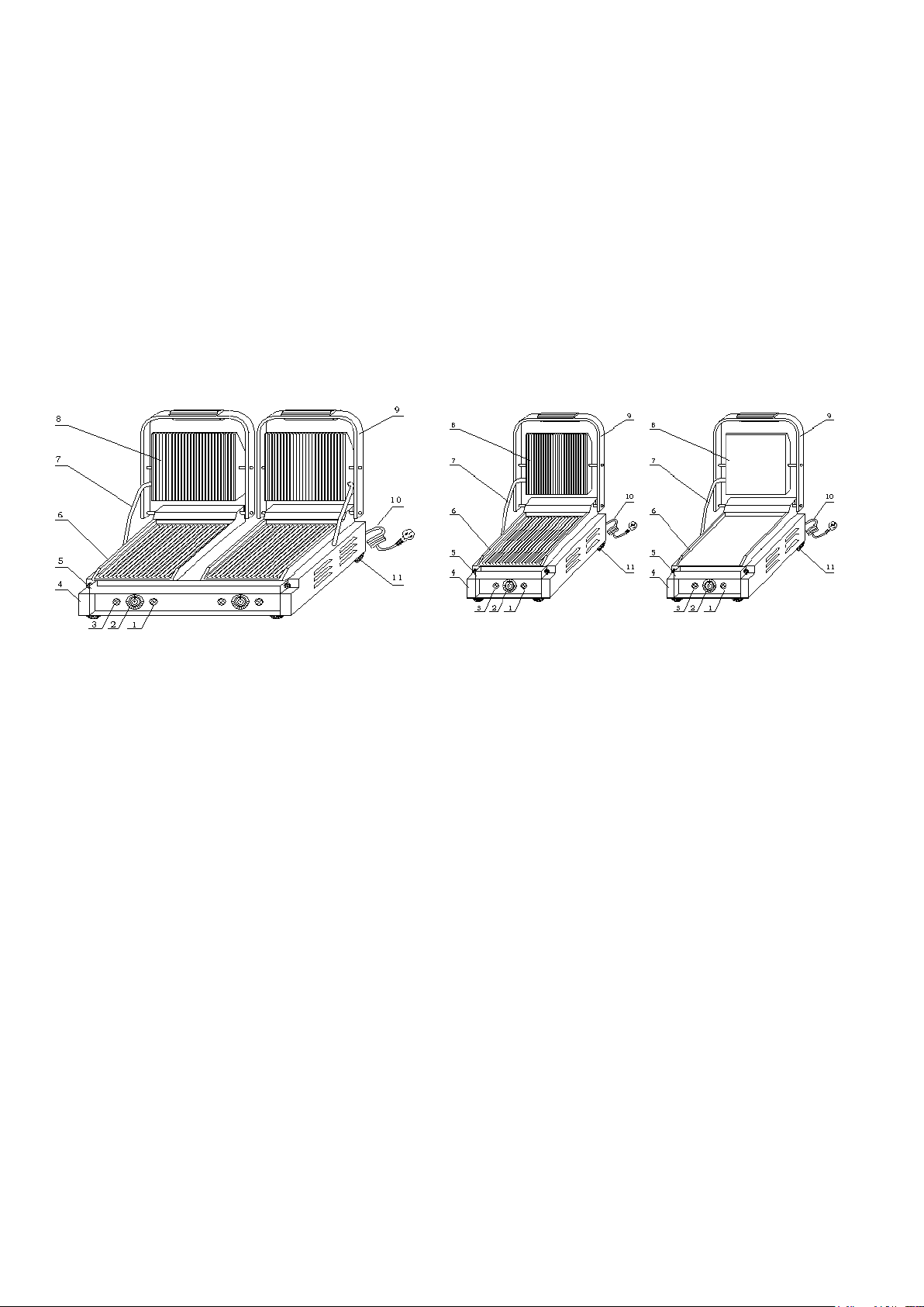
A. Exterior Structure
1—HEATING INDICATOR 2—TEMEPRATURE CONTROLLER
3—POWER INDICAOTR 4—BOTTOM BOX
5—OIL TRAY 6—LOWER MODULE PLATE 7—FEED WIRE TUBE 8—UPPER
MODULE PLATE 9—OPERATION HANDEL 10—POWER CORD
11—RUBBER FEET
B. Features of Function and Structure
1. The upper and lower module plates are enameled and are easy to be cleaned.
2. One-headed and double-headed grilling pans can be chosen freely.
3. Independent temperature controlling system are convenient to handle and can achieve
energy economy as well.
4. Internal temperature protector is reliable and safe.
5. Grilling temperature can be adjusted according to different requirements.
6. It is made by stainless steel and the drawer-style oil tray is also made of stainless steel.
7. It is easy to lift up and down and convenient to handle and maintain.
4

C. Basic Parameter
Name
Contact Grill single
Upper/lower ribbed
Contact Grill single
Upper/lower smooth
Contact Grill single
Upper ribbed/lower
smooth
Contact Grill single
Upper/lower ribbed
Contact Grill single
Upper/lower smooth
Model
PG-SA
PG-SF
PG-SC
PG-MA
PG-MB
Voltage
220~240V
50/60Hz
220~240V
50/60Hz
220~240V
50/60Hz
220~240V
50/60Hz
220~240V
50/60Hz
Power
1.8KW
1.8KW
1.8KW
2.2KW
2.2KW
Temperature
controller
number
1 1 1 1 1
Temperature
range
50~300℃
50~300℃
50~300℃
50~300℃
50~300℃
Upper grill
size
214×214(mm)
214×214(mm)
214×214(mm)
340×220(mm)
340×220(mm)
Lower grill
size
218×230(mm)
218×230(mm)
218×230(mm)
360×285(mm)
360×285(mm)
Dimension
290×395×210(mm)
410×370×220(mm)
410×370×220(mm)
Weight
13kg
13kg
13kg
15.5kg
15.5kg
Name
Contact Grill single
Upper ribbed/lower
smooth
Contact Grill double
Upper/lower ribbed
Contact Grill double
Upper/lower smooth
Contact Grill double
Upper ribbed/lower
smooth
Contact Grill double
Upper smooth/lower
ribbed
Model
PG-MC
PG-2SA
PG-2SF
PG-2SC
PG-2SD
Voltage
220~240V
50/60Hz
220~240V
50/60Hz
220~240V
50/60Hz
220~240V
50/60Hz
220~240V
50/60Hz
Power
2.2KW
3.6KW
3.6KW
3.6KW
3.6KW
Temperature
controller
number
1 2 2 2 2
Temperature
range
50~300℃
50~300℃
50~300℃
50~300℃
50~300℃
Upper grill size
340×220(mm)
214×214(mm)
214×214(mm)
214×214(mm)
214×214(mm)
Lower grill size
360×285(mm)
475×230(mm)
475×230(mm)
475×230(mm)
475×230(mm)
Dimension
410×370×220(mm)
570×395×210(mm)
Weight
15.5kg
27kg
27kg
27kg
27kg
5

Name
Contact Grill double
Upper/lower ribbed
Contact Grill double
Upper/lower smooth
Contact Grill double
Upper ribbed/lower smooth
Contact Grill double
Upper smooth/lower ribbed
Model
PG-2MA
PG-2MB
PG-2MC
PG-2MD
Voltage
220~240V
50/60Hz
220~240V
50/60Hz
220~240V
50/60Hz
220~240V
50/60Hz
Power
4.4KW
4.4KW
4.4KW
4.4KW
Temperature
controller
number
2 2 2
2
Temperature
range
50~300℃
50~300℃
50~300℃
50~300℃
Upper grill size
340×220(mm)
340×220(mm)
340×220(mm)
340×220(mm)
Lower grill size
759×285(mm)
759×285(mm)
759×285(mm)
759×285(mm)
Dimension
810×370×2 20(mm)
Weight
31kg
31kg
31kg
31kg
D. Transportation and Storage
Please handle the griller carefully and cautiously in transportation and do not turn it upside down
to prevent any damage to the shell and interior. The packed griller should be stored in the
storehouse ventilation and non-corrosive gas. Any weatherproof measures should be applied
when temporary storage.
E. Notes
1. The working voltage of the equipment should match that of the power supply.
2. Suitable switch, fuse breaker and three-phase socket should be installed near the
equipment.
3. There is an earth bolt at the back of the equipment. Please connect the earth wire in
compliance with the safety regulations reliably with copper cable of no less than 2mm.
4. Before using user should check whether connection is firm and voltage is regular and
earth connection is safe.
5. Do not put any object onto the upper module plate and shake the lift operation handle
with sudden force.
6. Cut off power supply while cleaning. Do not use wet towel with corrosive cleanser and do
not directly splash water on the equipment.
7. The adjustable temperature of the equipment is between 50~200℃. It is recommended
that the maximum working temperature normally should be 200~250℃.
8. Do not store any flammable objects near the equipment. The environment temperature
lower than 45℃, the humidity is under 85%.
9. The installation and maintenance of the equipment should be made by professional
technicians.
Special Notes
6

WARNING!
● This product is a commercial machine and it must be operated by trained cook.
● Do not dismantle and refit the machine.
Do not lift the upper module plate with sudden force and tilted installation.
The dismantlement and alteration can cause serious accident happens.
● Before cleaning, unplug the machine and cut off power supply.
Do not spray water directly to the product.
Water can conduct electricity and electricity leakage happens.
● Do not pat the product and put heavy object onto the product.
Incorrect operation can cause the equipment be damaged and dangerous.
● High temperature will cause scald.
When the equipment is in use and before or after using it, do not touch the box and
module plate because of high temperature.
● Do not use any power supply which is not coordinated with safety standards.
NOTICE!
● When the thunderstorm is coming, the electricity supply must be cut off soon.
It will avoid the equipment being damaged in cause of lightning stroke.
● Do not destroy the control panel and the surface of the machine with hard or sharp
things.
● When the machine finishes using , user should close main switch.
● The installation and maintenance of circuit must be done by certificated special
professionals.
If the supply cord is damaged, it must be replaced by the manufacturer or its service
agent or a similarly qualified person in order to avoid a calamity.
F. Operation Instruction
1. Before using, check whether the power supply installation is regular to make sure the
supplied voltage is coordinated with the using one.
2. Put the plug in the socket and turn on the power.
3. Turn the temperature controller clockwise to the temperature needed. The yellow
indicator is on that shows heating wire begins to heat and the upper and lower griddle
begins to raise temperature.
4. Temperature can be adjusted according to different food preferably within 180℃~250℃.
About 8 minutes is needed for the temperature to be raised to 250℃ from the power is
on.
5. When the temperature reaches 250℃, lift the upper module plate to a suitable place by
operation handle. Put some edible vegetable oil on the lower module plate and constantly
7

place the food on it. Close the plates and press the handle lightly. Keep an eye on the
food until it is suitably done.
6. When temperature reaches the setting degree, temperature controller can cut off power
supply automatically. At the same time, yellow indicator is off and green indicator is on. It
shows that electricity heating tube stops working for next turn.
7. At the lower front of the lower module is the oil tray. Substantial vegetable oil and the
animal oil from the meat grilled flow to the oil tray from the lower module plate.
8. Lift the upper module plate to take the sandwich and other food already done.
9. When the temperature is a bit lower, the temperature controller can get through power
supply automatically. The heating tubes restart to work to heat the module plates.
10. On completion of the work, temperature controller should be turned to the “off” place.
Unplug the equipment and cut off the power.
11. Notice: There is temperature limiter in the bottom box, the action temperature is 130℃,
and reset temperature is ‹40℃. When temperature is over the protective button works for
protection. When use it again, please use it after press the protective button.
G. Cleaning and Maintenance
1. Cut off the power supply before cleaning in case of accident.
2. Do not use wet towel with non-corrosive cleanser to clean the module plate, the surface
of the equipment and power cord. Direct wash by water is not permitted in case of any
damage of the functions.
3. If do not use it at any time, please turn off temperature controller and main switch.
4. Please store the equipment in a ventilated storehouse without corrosive gas after
cleaning when ceasing its work for a long time.
8

H. Troubleshooting
Troubles
Causes
Solutions
1. Module plates are out of
heating when the power and
heating indicator are both on.
1. Temperature controller is broken.
2. At least one of heating wires is
burned.
3. Temperature protector works.
1. Change temperature controller.
2. Change the burned heating tube.
3. Dismantle the bottom plate and use
hand to reset temperature
protector.
2. When the power is on and
temperature controller is
switched and heating indicator
is on and temperature can be
not controlled.
1. Temperature controller is out of
order.
1. Change temperature controller.
3. Indicator is not on when the
power is on and the heating
process is normal.
1. Indicator is broken.
1.Change
temperature controller.
The indicator is out of order
when the power is on.
1. Abnormal power supply or cut-off
power supply.
2. Fuse is burned.
1. Check power supply and connection
to make power supply be normal.
2. Change fuse.
Aforementioned troubles are just for reference. If any fault occurs, please cease using
and turn to professional technicians for check and repair.
I. Circuit Diagram
PG-SA PG-SF PG-SC PG-MA PG-MB PG-MC
9

PG-2SA PG-2SF PG-2SC PG-2SD PG-2MA PG-2MB PG-2MC PG-2MD
HL1, HL3----POWER INDICAOTR
HL2, HL4----HEATING INDICATOR
SA, SA1, SA2----TEMPERAUTRE CONTROLLER
E----GROUND CONNECTION
SB, SB1, SB2----TEMPERAUTRE CONTROLLER
EH1, EH2, EH3, EH4----HEATING WIRE
THE SHELL OF THIS MACHINE MUST BE EARTH GROUNDED FOR SAFETY SAKE.
THANKS FOR YOUR COOPERATION.
10

J. Daily Check
Before using
Whether the machine is tilted?
Whether the power cord is old, broken or damaged?
Whether the control panel is damaged?
After using
Whether there is strange smell?
Whether the upper and lower module plate cannot be
heated at the same time?
Is there any strange voice or is the machine out of
control while the machine is lifting?
WARNING!
● Must check the machine everyday.
Usually check the product that can avoid serious accident happens.
● Stop using if user feels that there are some problems in the circuit or machine.
Ask the special technicians to check and maintain the machine as soon as
possible.
1
2
3
4
5
6
7
8
9
10
11
12
13
14
15
16
17
18
19
20
21
22
23
24
25
26
27
28
29
30
31
32
33
34
35
36
37
38
39
40
41
42
43
44
45
46
47
48
49
50
51
52
Everyday notice the situation of the machine before or after using.
K. Solid Resolution Graph
11

1
2
3
4
5
6
7
8
9
10
11
12
13
14
15
16
17
18
19
20
21
22
23
24
25
26
27
28
29
30
31
32
33
34
35
36
37
38
39
40
41
42
43
44
45
46
47
51
52
21
49
50
48
Declaration: The structures of PG-SA/PG-SF/PG-SC/PG-MA/PG-MB/PG-MC are different, the
differences are: The upper and lower module plate of PG-SA and PG-MA are ribbed; the upper
and lower module plate of PG-SF and PG-MB are smooth. The upper and lower module plate of
PG-SC and PG-MC are upper ribbed and lower smooth.
12

Declaration: The structures of
1. HEATING INDICATOR
2.TEMPERATURE CONTROLLER
3.CROSS-HEADED SCREW M4×6
4. POWER INDICATOR
5. BOTTOM HULL
6. INTERNAL HEXAGON SCREW M6×10
7. FLAT SPACER
8. INTERMAL HEXAGON SCREW M5×25
9. FLAT SPACER
10. WISTING SPRING
11. REAR ROTARY AXLE
12. FASTONTING STAND
13. INTERNAL HEXAGON SCREW
M6×40
14. BACK UPPER COVERING BOARD
15. SCROSS-HEADED SCREW M4×8
16. SPRING PIN
17. EQUIPOTENTIAL GROUND SCREW
M6×15
18. POWER SUPPLY WIRE JACKET
19. POWER CORD
20. POWER GROUND SCREW M5×15
21. GRILL OF LOWER MODULE
22. UPPER MODULE BOARD
23. CROSS-HEADED SCREW M4×8
24. HEAT-INSULATED COTTON OF
UPPER MODULE
25. PLATEN OF UPPER ELECTRIC
HEATING TUBE
26. GRILL OF UPPER MODULE
27. ELECTRIC HEATING TUBE OF
UPPER MODULE
28. INCOMING LINE TUBE
29. SPRING CHECK RING FOR AXLE
30. SPRING CHECK RING FOR TUBE
31. AXLE OF UPPER MODULE
32. INTERNAL HEXAGON SCREW
M5×16
33. INTERNAL HEXAGON SCREW M6×8
34. HANDLE
35. FRAME OF OPERATION HANDLE
36. OIL TRAY 37. HALF OF CHEESE
HEAD SCREW M6×12
37. HALF OF CHEESE HEAD SCREW
M6×12
38. SMALL BALL
39. HEAT-INSULATED COTTON OF
LOWER MODULE
40. PRESSURE PLATE FOR COTTON
41. CROSS-HEADED SCREW M4×20
42. AMPHENOL CONNECTOR PLATE
43. CROSS-HEADED SCREW M4×8
44. CERMIC CONNECTORS
45. TEMPERATURE LIMITER
46. HEXAGON SCREW M6×20
47. RUBBER FOOT
48. PRESSURE PLATE FOR
ELECTRIC HEATING TUBE OF LOWER
MODULE
49. ELECTRIC HEATING TUBE OF
LOWER MODULE
50. INTERNAL HEXAGON SCREW M6×8
51. BOTTOM BOARD
52. CROSS-HEDED SCREW M4×8
PG-2SA/PG-2SF/PG-2SC/PG-2SD/PG-2MA/PG-2MB/PG-2MC/PG-2MD are different, the
differences are: The upper and lower module plate of PG-2SA and PG-2MA are ribbed; the
upper and lower module plate of PG-2SF and PG-2MB are smooth. The upper and lower module
plate of PG-2SC and PG-2MC are upper ribbed and lower smooth. The upper and lower module
plate of PG-2SD and PG-2MD is upper smooth and lower ribbed.
13

Waste disposal
Discarding old devices
At the end of its service life the discarded device has to be disposed in accordance with the
national regulations. It is advisable to contact a company which is specialized in waste disposal,
or just contact the local disposal service in your community.
WARNING!
To exclude any abuse and the dangers involved make the waste device unfit for use before
disposal. For that purpose disconnect device from mains supply and remove mains connection
cable from the device.
CAUTION!
For the disposal of the device please consider and act according to the national and local rules
and regulations.
WARRANTY
iMettos warrants to the original purchaser of every new product, under normal and proper use
and maintenance service as specified by iMettos and upon proper installation and start-up in
accordance with the instruction packet supplied with each unit. iMettos’ obligation under this
warranty is limited to a period of two (2) year from the date of original installation.
WARRANTY CLAIMS
All claims for parts must be made directly through iMettos. All claims should include:
Personal Details: Products Details:
Your name: Model number:
Your company: Serial number of the product:
Address: Date of purchase:
Email: Proof of purchase :
Phone:
Pertinent information supporting the existence of the alleged defect.(Such as picture etc.)
Please send the above information to services@imettos.co.uk
Our warranty departments will according to the actual situation and reply you within 24hours.
14

iMettos Limited
www.imettos.co.uk
15
 Loading...