


TRADUCTION OF THE ORIGINAL INSTRUCTIONS FOR USE
BS 300/60 AFI-E ED.2010 rev.00
1/61
IMET Spa
Loc. Tre Fontane - Cisano Bergamasco
Tel. 035/4387911 - Fax. 035/787066
Web site: www.imetsaws.com
E-mail: imet@imetsaws.com
Automatic, hydraulic bandsaw BS300/60 AFI-E
USER’S INSTRUCTIONS

TRADUCTION OF THE ORIGINAL INSTRUCTIONS FOR USE
BS 300/60 AFI-E ED.2010 rev.00
1/61
1
We recommend to read carefully the information here included in order to install, use and maintain correctly
and safely this machine.
Please refer always to this instruction manual in case of assistance service need and keep it carefully for all
the machine life. The reference numbers in Italy are +39 035 4387918 and +39 035 4397828.
A consequence of the continuous improvement of the product is that some images/descriptions here included
could not correspond to the improved features of the machines.
Your kind collaboration would help us in intevening asap.
In the enclosed Compliance Declaration you will find the Safety and Reference Norms applied during the
planning and construction of this machine.
The choice and the use of the parts have been made by considering the conditions of use and the long
machine life.
The identification plate, with the serial number, is fixed on the front right angle of the base or on a side of
control box.
1.1 - ATTACHED DOCUMENT FOR E.M.C. ( INDUSTRIAL ENVIRONMENT)
The user is responsible for installation and use of this machine in compliancewith the
manifacturer's instructions shown in this manual. This plant meets the protection requirements in
accordance with the Directives 2006/42/EEC and 2004/108/EEC,
as for electromagnetic compatibility (EMC).
In particular, it follow the technical instructions of the Rules EN55011,EN50082-2 and it has been
realized for industrial and not for household use.
In the event that should be electromagnetic interferences the user is responsible for solving the
problem together with the technical assistance of the manifacturer.
Before installing the machine the user must take into account possible electromagnetic problems
of the working area. In particular, we suggest installing the plant away from:
-signalling, control and telephone cables; -radiotelevision transmitters and receivers;
-computers or controlling and measuring instrument; -safety and protection devices.
The electric supply cable must be kept as short as possible, well right and without wires.
The covers, the door and the frame must be suitably closed when the plant is operating.
Under no circumstances the plant must be modified except for adjusting and changing established
by the manifacturer.
Follow the maintenance schedule.

TRADUCTION OF THE ORIGINAL INSTRUCTIONS FOR USE
BS 300/60 AFI-E ED.2010 rev.00
2/61
===========================================================================
CE DECLARATION OF CONFORMITY (encl. II A DIR 2006/42/CE) / 01
===========================================================================
THE MANUFACTURER : IMET S.p.A
Località Tre Fontane
24034 - CISANO BERGAMASCO –BG- ITALIA
HEREBY DECLARES THAT
in designing and manufacturing the machine described here below , we have considered the most important
requirements of safety and health dictated by the European Directives of the Machine Security. Remember
that this declaration loses its validity if machine is modified without our agreement.
Trade name BAND SAWING MACHINE FOR METALS
Code / Model / Type
Manufacturing year
Serial number
IT IS IN COMPLIANCE WITH THE DIRECTIVES
DIRECTIVE 2006/42/CE OF THE EUROPEAN PARLIAMENT AND OF THE COUNCIL OF THE
17TH/05/2006 REGARDING THE MACHINES AND THAT MODIFIES THE DIRECTIVE 95/16/CE;
DIRECTIVE 2004/108/CE OF THE EUROPEAN PARLIAMENT AND OF THE COUNCIL OF THE
15/12/04 REGARDING THE ELECTROMAGNETIC COMPATIBILITY -EMC-
DIRECTIVE 2006/95/CE OF THE EUROPEAN PARLIAMENT AND OF THE COUNCIL OF THE
12/12/06 REGARDING ELECTRICAL EQUIPMENT FOR USE OF LOW VOLTAGE -LVD-
HARMONIZED STANDARDS REFERENCE EN.12100-01; EN 55011, EN50082-2, EN 13898, EN
60204 LEGISLATIVE DECREE N.17 OF THE 27TH OF JANUARY 2010.
AND AUTHORIZING THE PERSON LISTED BELOW TO ISSUE THE TECHNICAL FILE.
Date : 01.01.2010
The signatory identification The manager
Angelo Meroni
-------------------------------------------------------------------------------------------------------------------------File : Machine no. Delivery note no Dated
…………………….
………………..
………………..

TRADUCTION OF THE ORIGINAL INSTRUCTIONS FOR USE
BS 300/60 AFI-E ED.2010 rev.00
3/61
---------------------------------------------------------------------------------------------------------------------------

TRADUCTION OF THE ORIGINAL INSTRUCTIONS FOR USE
BS 300/60 AFI-E ED.2010 rev.00
4/61
3 - MACHINE NOISE
The decibel pointed out in the workplace in the conditions under described is appointed to the simoultaneous
working of some machine parts in motion ( it depends on the detailed cycle ) added to that one of the tool
when is cutting the workpiece.
In several moments the decibel are pointed out to note the different using conditions.
The phon-meter is placed at about 1 meter near the machine and at about 1,60 m from the floor.
The results of each test is in dBA and they mean the average of 3 tests made from the: left side,
opposite side, right side.
For any machines the using conditions are the following :
When running at the highest blade speed without cutting: dBA 63
When cutting a steel solid (St12=~C20 diameter 100mm) at a suited blade speed: dBA 75
( the measuring is = + - 2dB ).
In the standard production the test is made by a same machine of above mentioned one, in compliance with
E.C. safety norms 2006/42/CE . Usefull is the reference Guide 2003/10/EEC.
The use of the machine in bad conditions or the use of the wrong tools cause also sensitive alterations of
these tests and it is prejudicial for the health of the staff and for the good results of the work .
Most of all the noice depends on the cutting material, on its sizes and on the locking system.
By expecting that above mentioned decibels could be exceeded, we recommend the operator the using of the
personal means of protection ( head phones, plugs etc. ) in case of working a long time at highest
levelspositioning/clamping in the vice, taking into account other possible machinery running nearby
and the characteristics of the working place
3.1 - ADDITIONAL HEALTH AND SAFETY REQUIREMENTS
This type of machine, manually controlled during some working operations, must respond to further health
and safety requirements as specified by article 2.2 of the Annexed I of the European Directive2006/42/EEC .
In particular, the level of vibrations emitted by the machine while in use must be clearly specified in the
instructions.
This machine does not emit vibrations of a level higher than 2,5 m/s 2
The measurement procedure used conforms to the general norms applied to this type of machine.
Usefull is the reference Guide 2002/44/EEC.
As in the preceding paragraph, using the machine in unsuitable conditions or using the wrong tools
can cause changes affecting this value, endangering the health of the work force as well as the
quality of production.
Vibrations emitted during cutting may be amplified by the material, by its dimensions and its
positioning/clamping in the vice.

TRADUCTION OF THE ORIGINAL INSTRUCTIONS FOR USE
BS 300/60 AFI-E ED.2010 rev.00
5/61
4 - GUARANTEE NORMS
I.ME.T. offers a wide range of sawing machines and accessories, destined to who buys/uses them as part of
a commercial or professional activity.
The manufacturer grants that this product has been strongly controlled and that there are no defects in the
used and working materials for a period of 12 months from the date of the delivery note.
The italian law D.L. n° 24 issued on 02/02/2002 and valid since 23/03/2002 (which carries out the European
Directive 1999/44/CE) indicates different terms only for convenience products for private use.
If the user points out some defects to the manufacturer during the warranty time, the manufacturer will
replace the components that are considered defected.
In case of reparation of the machine during the warranty time the shipment will be accepted only if the
delivery is Free Destiny (that is the freight costs are supported by the owner of the machine), and the return
of the machine to the customer is considered EX WORKS.
If the manufaturer is not able to remplace a component within an acceptable time, both companies
(manufacturer and user) will reach an agreement for satisfying completely the needs of the user.
The a.m. warranty is not valid in case of accidental damages, or defects provoked by a wrong use of the
machine or maintenance, by variations made on the machine, or by the use of the machine in a place not
corresponding to the indicated enviromental specifications.
4.1 - The manufacturer does not offer further warranties, written or spoken, explicit or implicit of its products
and does not offer implicit warranties on saleability or adequacy for particular uses not foreseen by the
agreement.
The a.m. limitations and exclusions can also be not applicable in Countries, where there are no implicit limits
of warranty time on the products. Anyway each implicit warranty is limited to a time of 12 months from the
date of the delivery note.
4.2 - The date of manufacture, deducible from the serial number placed on the machine, is a very necessary
reference for the warranty, for the assistance after-sale and for the identification of the product.
Each tampering on the products, expecially the installation of safety devices, will relieve the manufacturer of
any kind of responsability.
The parts most subject to rapid and continuous wear are not included in the warranty (for example:
transmission belts, gaskets, oils, blades, and so on).
For the electrical, electronic and hydraulic equipments and for the other equipments having its own
individuality (of which there is the possibility to know the name of the constructor), the manufacturer gives to
the user the same warranty received by the primary constructor of these parts.
4.3 - The components replaced during the assistance operated by the manufacturer have a warranty of 6
months from the installation date indicated on the Technical Service paper, one copy of which is given to the
owner.

TRADUCTION OF THE ORIGINAL INSTRUCTIONS FOR USE
BS 300/60 AFI-E ED.2010 rev.00
6/61
5 - SUMMARY pag.
1- PREMESSA 2
2 – CONFORMITY DECLARATION 3
3 – AIR NOISE 4
4 – GUARANTEE NORMS 5
5 – Index 6
6 – Technical characteristics 7
7 – Installation – minimum requirements 9
8 – Moving and transit 9
9 – Fittings/optionals 11
10 – Blade choice 12
11 – Foreseen use and controindications 14
12 – Machine description 17
13 – Work preparation 18
14 – Band tensioning 19
15 – Functioning 20
16 – Regulations 25
17 – Maintenance – for the user 27
18 – Band running-in 28
19 – Machine running-in 28
20 – Draining of used/produced substances 29
21 – Trouble-shooting 29
22 – Machine demolition 31
23 – Spare parts 32
24 – Maintenance – for qualified technicians 33
Electrical drawings
Hydraulic diagram
Spare Parts drawings

TRADUCTION OF THE ORIGINAL INSTRUCTIONS FOR USE
BS 300/60 AFI-E ED.2010 rev.00
7/61
6 – TECHNICAL DETAILS
Automatic electronic bandsaw with numeric control and hydraulic working , suitable for cutting metal profiles
and solids from 0 to 45 deg. left in automatic cycle, from 0 to 60 deg. left in semiautomatic cycle Material
feeder equipped with recirculating-ball screw. In compliance with E.C. - CSA - UL Safety Norms and with the
Norms of Electromagnetic Compatibility (EMC
STANDARD MODEL EQUIPPED WITH:
2 SPEED Three-phase motor, - with band speed 35/70 m/min. - electrical components complying with E.C.
Norm EN60204-1, EN55011, EN50082-2
- low voltage (24V), main switch with interlocking attachment and minimum tension coil, thermo-magnetic
overload motor protections, emergency stop
- easy to use CNC control; all operating functions of the machine are programmed from the control panel,
Showing of the operating conditions, band speed, piece counter and number of pieces still to cut on an
alphanumeric display, , - autodiagnostics circuit displaying error CODES wholly controlling the machine
actuators - front fixed screw vice with hydraulic action, jaws height 130 mm - quick and positive location at 0
feeder equipped with recirculating-ball screw, 300 mm maximum opening, 4 mm minimum stroke, 210 mm
minimum scrap-end,.- feeder vices fitted to a floating plate, sliding by ball-bushing on chromium-plated and
tempered guides- monobloc floor stand predisposed for handling with lift truck Connection for loading roller
tables - unloading chute -removable chip tray and tank, coolant pump and washing spray gun, hydraulic unit
with oil. New band-cleaning device by means of a brush, , - bi-metal band, wrenches and manual of
instructions, maintenance and spare parts.
WIDE RANGE OF ACCESSORIES: Two pressure reducers for hydraulic vices with gauges, upper rollers for
cutting more pieces side by side (max dimensions 300x100 mm, only for straight cut) , RTS = modular
loading roller tables, 400 mm wide and 2 m long.
If not differently indicated, all data reported in this manual refer to the standard version,
suitable for working at 400 V / 50 Hz THREEPHASE .
= cutting capacity ( max. dimensions on PROFILES & TUBES)
= BLADE DIMENSIONS = WEIGHT =VICE OPENING
= motor choice and blade speeds (at 50 Hz);
mm.
Kw
Mt/min
mm.
Kg.
mm.
mm.
mm.
2765 +-10
X27X0,9
1,5
3~
18 to
110
300
635
255
230
300x180
210
190
200X160
1,5/1,8
35/70
300
630
135
110
130X100
N.B. If the device of MINIMAL LUBRICATION is placed on the machine, the cutting capacity is reduced about
10 mm due to the spray nozzles on the anterior band guide.
Dimensions
(mm)
B
width
L
lenght
H
height
H min.
worktable
In use
1800
1850
1880
870
For transport
1800
1750
1600

TRADUCTION OF THE ORIGINAL INSTRUCTIONS FOR USE
BS 300/60 AFI-E ED.2010 rev.00
8/61
7 - INSTALLATION
The machine can work according to the parameters provided by the manufacturer if it is rightly installed and
the minimum requirements are observed, as follows :
- Machine must be used indoor and with temperatures from +5 to + 40 ° C.
- The relative humidity of the environment must not go over 95%.
- The nominal value of the voltage of electric energy must be between + - 10 and the frequency of the
nominal value must be between + - 2%.
The floor must have good characteristiques of capacity and level.
Floor space, operator position and working area are indicated in the included drawing that concerns the
machine only without fittings as optional.
Work table must be leveled: by using the screws and nuts (NOT SUPPLIED) put in the little feet holes fix the
machine to the floor .
The included electrical schemes reproduces the necessary details to arrange the connections, to be
predisposed for 5KW power request.
Grounding of all electric parts thanks to a GREEN/YELLOW wire, linked via a TN system to the power supply
cable. A supplementary grounding point – marked “PE” – can possibly be located on the metallic structure of
the machine.
7.1 - DIFFERENTIAL PROTECTION
For the connection of the differential protection on the power supply line it is necessary to use
switches with a threshold of interference on the power dissipation of not less than 300 mA (size 0.3
A or higher is recommended), having possibly time adjustment availability (0>1.5 sec).
E.M.C. Electromagnetic noise
This machine has been foreseen for industrial and not for household use. In the event that should be
electromagnetic interferences the user is responsable for solving the problem together with the technical
assistance of the manufacturer. Before installing the machine the user must take into account possible
electromagnetic problems of the working area. In particular we suggest to install the plant away from:
- signalling, control and telephone cables;
- radiotelevision transmitters and receivers;
- computers or controlling and measuring instruments;
- safety and protection devices.
8 – TRANSPORT & LIFTING
For the transport of the machine only the methods indicated below are possible. However, be sure that the
means of transport snd lifting are able to stand the machine's weight and its packing (about 1000 Kg):
WARNING
The personnel in charge of loading, unloading and moving the machines should use protective gloves.
WARNING
When lifting or moving the machine, or a part of it, take care of clearing the operations area of the people,
considering also an appropriate safety area around it, so as to avoid any risks of injuring people or damaging
things located nearly.
Special packings – wooden crate , wooden case –may be predisposed on request, by charge.
ALL THE OPERATIONS THAT INVOLVE MOVING THE MACHINE MUST BE CONDUCTED WHILE
RESPECTING THE FOLLOWING BASIC RULES:

TRADUCTION OF THE ORIGINAL INSTRUCTIONS FOR USE
BS 300/60 AFI-E ED.2010 rev.00
9/61
+ When moving the machine, an appropriate means has to be used, with a loading capacity higher than
the weight to lift, which is indicated on the machine.
+ When choosing and then using equipment such as ropes, chains or lifting belts, be careful about their
geometry during the lifting and about the consequent actual loading capacity.
+ The machine is structured so as to offer lifting points, which are appropriately indicated and will have to
be used for lifting it.
+ In case the lifting belts touch parts of the machine, nylon belts are required; ropes or chains wrapped
with jute or clean covering can also be used. A great care is necessary while slinging and moving the
machine in order to hinder damages.
+ All operations have to be conducted with graduality, so as to avoid jolts and dangerous situations.
+ The person in charge of the operations has to make sure that all the national, local and company norms
in reference to injury prevention and work safety are respected.
+ Onr or more areas for material storage have to be identified.
Transport with machine at sight
This type of transport is usually chosen for deliveries by covered truck, in case of short trips. The machine is
wrapped with thermoplastic material in order to assure a suited protection of all its parts; the machine is then
loaded on a truck and should be wrapped with ropes that tie it up . To lift it, use a forklift from front side of
machine, with forks length 1.5 m or more.
Warning: if machine is delivered by open trucks, please cover it !
Transport with wooden crate or wooden case. ( BY REQUEST , ON CHARGE )
The machine is wrapped with thermoplastic material in order to assure a suited protection of all its parts; then
it is packed into a wooden crate or cage to protect it from collisions, inclement weather and so on.
To lift it, use a forklift from front side of machine, with forks length 1.5 m or more (see picture ).
You need to follow the indications you find on the packing before proceeding to moving or opening it.
WARNING
The size of the packing varies according to the machine ordered and its configuration.
WARNING
The machine is fixed to the packing by means of screws, so as to hinder that it can move during the transport
(see drawing in the following page)

TRADUCTION OF THE ORIGINAL INSTRUCTIONS FOR USE
BS 300/60 AFI-E ED.2010 rev.00
10/61
FITTINGS ASSEMBLING
The installation informations are supplied together to the same fitting, but we include herebelow a little
working description.
Loading roller table- To rightly install the loading roller table, first of all it is necessary to level and to
adhere the machine.
Therefore level the loading roller table to the same level of the work table and the back supporting jaws by
beginning to that nearest the machine. For very long workpieces adhere the pedestals on the floor and
recycle the coolant transported by the workpieces that have to be cut .

TRADUCTION OF THE ORIGINAL INSTRUCTIONS FOR USE
BS 300/60 AFI-E ED.2010 rev.00
11/61
Upper roller for simultaneous cutting of several bars- it is an optional - together with the vertical vice, it
allows to move and to lock a group of bars suitably prepared, or tubulars placed side by side ( not one on the
other ) . The maximum dimensions that can be reached are : width 280 mm., height .100. mm., 20 mm.
minimum.
Additional supporting roller for the feeding - it increases the support of the material to cut ( when the bar
is almost finished ). You can assemble it and dismantle with great ease.
Hydraulic vertical vices for cutting bundles, connected to the standard vices. They allow to clamp and feed a
bundle of bars – maximum breadth 250mm, minimum breadth 110mm, maximum height 120 mm.
Minimal lubrication system – This device, applied to the saw, allows to eliminate almost completely the
traditional coolant system, keeps the material much cleaner and avoids to waste cutting oil and water. It
works only during the cut.
It is comprised of a nozzle - 1/RI0463 - with 3 micro-holes, a tank with devices to adjust the quantity of oil and
the air pressure. The switch of the electric system - 3/RI0462 - working with low tension 24V AC allows to turn
it off at any moment and use the normal coolant system. . Remove the nozzle 1/RI0463 to obtain the maximal
cutting capacity.

TRADUCTION OF THE ORIGINAL INSTRUCTIONS FOR USE
BS 300/60 AFI-E ED.2010 rev.00
12/61
Voltage transformer - place it between the electric supply of the premises and the electric supply of the
machine. It allows to work with a different voltage than the standard one (that is 400V / 50 Hz). Available
voltages: 230V, 460V, 500V, 575V.
BAND CHOICE
In this paragraph we recommend the type of cutting band in accordance with the material to use . To get the
best performance from this machine it is necessary to undestand the right use of the used tools and what
you have not to do with them.
The band you have to use must have the following sizes ( in mm. ) :
maximum lenght = 2770
minimum lenght = 2750
total height = 27
thickness = 0,90
Blades with a different thickness can be utilized by changing appropriately the width of the blade guides (see
the paragraph ADJUSTMENTS ) and the band tension.
The blade material is also important; generally the bi-metal blade is used, with different levels of HARDNESS,
named M42 or SVGLB (for general purpose: tube, solids and profiles, available in all pitches), M51 or
SHL (preferred for big solids of hardened steel, INOX material too, available in 3/4 and 2/3 pitch).
The teeth hardness increases - and the fragility too - by going from the material M2 to the M51.
To make a good cut it’s crucial to choose the right pitch (t) or NUMBER OF TEETH PER INCH (z). The
blade must generally have the toothing as follows:
- small teeth when cutting thin materials, tubular and profiles.
- big teeth when cutting solids or pieces with a long cutting section (for example the central part of a U
profile), or in case of softer materials such as aluminium, copper, soft bronze.
By choosing the suited pitch you can avoid a lot of mistakes and you can get a good blade penetration and
the necessary room for the chips. If you cut more pieces at the same time, you must consider them as a
single piece (that is, you have to consider the total size). The enclosed chart gives the necessary
information for a correct choice. It can however be updated or modified by the user according to his
personal experiences.
Even if there are blades with constant pitch, most bandsaws allow the use of blades with variable pitch, that
is, groups of teeth having different pitch one from each other, which reduce vibrations and noise and improve
the quality of the cut and the cutting performance.
SUGGESTED PITCH
SOLIDS
Outer
Diameter
(mm)
BIG
PROFILES
Wall
Thickness
(mm)
PROFILES
Wall
Thickness
(mm)
BUNDLE
Lenght
to Cut
(mm)
REF.
VARIABLE
CONSTANT
14 M42
- - 1,5 max
-
10/14 M42
10 M42
- - 1 a 2
-

TRADUCTION OF THE ORIGINAL INSTRUCTIONS FOR USE
BS 300/60 AFI-E ED.2010 rev.00
13/61
8/12 M42
8 M42
20 max
-
2 a 4
-
6/10 M42
6 M42
40 max
-
4 a 8
-
5/8 or 5/7 M42
5 M42
30 a 80
6 a 12
-
50 a 100
4/6 M42
4 M42
40 a 90
10 a 20
-
70 a 120
3 / 4 M42 o M51
3 M42 o M51
70 a 150
15 a 25
-
100 a 200
2 / 3 M42 o M51
2 M42 o M51
120 a 230
Oltre 25
120 a 300
These cutting recommendations refer to 100 mm. diameter solid bars and a standard saw of our
product range. For 2-speed machines we suggest the motor speed to use; when it’s into a bracket ( ) it is
recommended to use a machine with ESC, which grants a continuous blade speed variation.
If the size of the material decreases, the indicated figures can be increased, considering also the
machine model and its performance and/or some accessories, for example the ESC (Electronic Speed
Control):
If the material size increases, it is necessary to decrease the indicated values, considering also the
machine model and its performance and/or some accessories, such as the ESC (Electronic Speed Control):
Using manually a saw often means a significant variation of the cutting times, because of the inconsistent
down-feed speed.
MATERIAL
GROUP
i.e. DIN
denomination
DIN N°
Maximum
BLADE
SPEED
m/min
Minimum
BLADE
SPEED
m/min
MOTOR
SPEED
(1or2)
FEED
FORCE
COOL
ratio
1)STRUCTURAL
St37 St42
10037-10042
60
40
1.
LOW
10%.
St50 St60
10050-10060
50
35 1 LOW
10%
HARDENING
C10 C15
10301 10401
45
35 1 LOW
15%
16MnCr5 20CrMo5
17131
40
30 1 Low/Me
10%
AUTOMATIC
9S20 10SPb28
10711
70
50
1 2
LOW
15%
BEARING STEEL
100Cr6
13505
40
25 1 Med/Hig
5%
SPRING
65Si7
15028
40
30 1 Med/Hig
5%
2)TOOL STEEL
C80W1
11525
40
30
(1)
HIGH
5%
ALLOYED
210Cr12 X155CrVMo
12080 12379
30
20
(1)
HIGH
dry
X40CrMoV51
12344
35
20
(1)
HIGH
5%
HIGH SPEED
S-6-5-2-2
13243
30
20
(1)
HIGH
5%
INOX STEEL
X5CrNi18 X10Cr1810
14305
30
20
(1)
HIGH
5%
3)SPECIAL
NiCr19NbMo
20
15
--
HIGH
20%
NiMo30
20
15
--
HIGH
15%
NiCr13Mo6Ti3
20
15
--
HIGH
15%
TITANIUM
Ti1
37025
30
20
(1)
HIGH
10%
G-TiAl6V4
37164
35
20
(1)
HIGH
10%
4)CAST IRON
GG15 GG30
--
50
30 1 Med/Lo
dry

TRADUCTION OF THE ORIGINAL INSTRUCTIONS FOR USE
BS 300/60 AFI-E ED.2010 rev.00
14/61
5)NOT-FERROUS
AL99.5 GalSi15Mg
--
300
50 2 Med/Lo
2%
BRONZE
CuSn6 CuSn6Zn
--
120
40
2 1
Med/Hig
2%
COPPER
G.Cu Ke.Cu
--
200
50
2
LOW
2%
3. INSTRUCTIONS FOR USE AND WARNINGS
This machine can make automatic work cycles, however at the end of each one the operator has to remove
the material that has been cut and possibly change the cutting conditions. Therefore the saw sometimes
must be manually adjusted and then it works in automatic cycle (so the operator is not indispensable).
The working cycle ends when the machine stops; in order to begin a new cycle, the starting procedure will
have to be repeated.
This machine is designed and manufactured so as to be safely used by the operator, provided that it is
properly operated . No protections will ever suffice if the operator does not work with due caution, does not
make sure that the machine is in top operating conditions and does not follow the instructions below.
You must remember that the machine is designed to CUT METALS with a sharp tool, and you are
responsible to see that it is operated in a SAFE and CORRECT manner.
1. make sure that the machine is properly installed and electrical installation is proper.
2. be sure you are familiar with all operating, safety, and applications information before running this saw.
3. see that all who operate this machine are properly trained and fully aware of all safety practices.
4. do not expose yourself or other people to any risk.
5. insist on proper personal protective equipment and practices.
6. maintain all factory-installed SAFETY DEVICES and make sure that these are never removed or altered or
restricted in any way.
7. the operator must have a safe and organized work area with suitable light and operating room.
8. the whole equipment has to be correctly and constantly maintained and inspected on a regular basis.
9. never use tools with different features from those for which the machine is designed for.
10.never use this machine to cut material bigger than the cutting capacity.
11. keep the cutting area clear of tools or other loose objects.
12. never operate the saw unless all protections are in place.
13. NEVER WEAR loose clothing, long sleeves, large gloves, jewelry, or any other items that may be trapped
into a part of the equipment. Confine long hair.
14. always disconnect the power at source when performing maintenance or making adjustments.
15. never insert hands or arms into or near the cutting area while machine is running.
16. properly clamp the material in the vice and never hold it with your hands.
17. support suitably the bar on both sides of the machine to prevent falling.
We recommend to connect an unloading table in case the cutting length of the material is longer than the
distance between the blade and the right edge of the saw.
18. when cutting very short pieces, make sure they do not jam into the blade.
19. if the blade becomes jammed, turn immediately off the emergency locking button, then move the cutting
unit to the CUTTING START position. If this is not possible, open the vice and move the piece, check that the
blade or teeth are not broken, if so replace it.
20. never change the working conditions when cutting, with exception of those specifically allowed (for
example, changing speed with the Inverter).
21. do not move the saw while cutting and avoid its instability.
22. wear personal safety equipment, if required for a safe operation.
ALWAYS OPERATE THE MACHINE SAFELY,
USING COMMON SENSE AND ALERTNESS
On some parts of the machine there are some stickers which warn about the safety measures that have to be
taken by the operator who runs it. Their meaning (easy to understand) is indicated in the following chart

TRADUCTION OF THE ORIGINAL INSTRUCTIONS FOR USE
BS 300/60 AFI-E ED.2010 rev.00
15/61

TRADUCTION OF THE ORIGINAL INSTRUCTIONS FOR USE
BS 300/60 AFI-E ED.2010 rev.00
16/61
OPERATOR’S SAFETY
This section illustrates the safety protections applied on the saw, according to the current legislation in the
field of safety.
3.2.1. ELECTRIC EQUIPMENT – Norm EN 60204-01
. Electric board closed with screws - general switch
. Marking of the electric components used, according to the indications on the electric scheme
. Control circuit with 24V tension – Control transformer with fuses on input and output
. Earthing of all electric parts with a dedicated GREEN/YELLOW wire, connected with a TN system to the
supply cable. A supplementary earthing point – indicated with PE – can be located on the metallic structure of
the machine.
. Minimum tension coil that prevents accidental restarting after a lack of tension.
. Protection from overloads and high temperature thanks to bimetal thermo-protectors placed directly in the
blade motor
. Emergency button for interrupting immediately all the movements of the machine. In order to restore all the
functions, rotate the button half a turn.
. Sensor of the blade tension: in case the blade breaks or the tension strength diminishes, the machine stops
immediately
. Sensor of the closing of the blade protection: if it opens during the working, the machine stops.
. The stops caused by one of the aforementioned devices needs a complete restoring of the working cycle
3.2.2 – PROTECTION AGAINST ACCIDENTAL CONTACTS
. Complete metallic protection of the blade and the pulleys, the blade-cleaning brush and the back bladedriving pads
. Forward metallic moving guard, fixed to the forward blade-driving pad. It assures the coverage of the blade
in every position, except for the stretch of blade which makes the cut. Joint to the blade-driving pad, it can be
opened only after the opening of the main protection
. Positioning of the saw blade thanks to 2 buttons located on the control board, in order to limit the width of
the danger area to the stretch of blade strictly necessary for the cut.
. During the cycle an automatic approaching device stops the saw blade near the material, in order to start
the cut.
. Clamping vice with a maximum stroke of 7 mm, according to the norms on automatic closing
. Guard extended to both sides which retains the coolant used during the cut, preventing its spilling on the
floor
. Parts of the machine with suitably chamfered or rounded angles
3.2.5. LIGHTING OF THE WORKING AREA
An inadequate lighting can cause accidents to the operator, who consequently needs a suited lighting in the
working area. In case of a lack of precise indications (for example, norm ISO 8995) for special areas, we
advise to supply a lighting equal to 750 LUX.
MACHINE DESCRIPTION, E.C. SAFETY NORMS
Automatic electronic band sawing machine with hydraulic movement . The head swivels from 0 deg. to 60
deg. left of metal profiles and solids.

TRADUCTION OF THE ORIGINAL INSTRUCTIONS FOR USE
BS 300/60 AFI-E ED.2010 rev.00
17/61
It is not suitable for cutting wood or similar materials ( cfr.D.M. 2006/42/CE ).
It automatically makes a working cycle usually consisting of :
Locking material, approaching and cutting , tool return, unlocking material and its displacement for a new cut.
The operator has to adjust the cutting parameters , to adjust the saw frame swiveling to make the inclined
cuts , to program the strokes quantity , the lenght and the quantity of pieces, and the cycle starting .
In designing and manufacturing this machine, we have considered the requirements of the Machine Directive
(2006/42/ EEC and so on..), important document valid in all E.E.C. Countries. Furthermore we have
considered the norms as type A and B in the case that specifications of type C are not available.
The choice and the use of the parts have been made by considering the conditions of use and the long
machine life.
From the position of the work, in front of the frontal vice, the operator has the possibility to actuate the
controls and to control the good working of the machine.
In the other paragraphs you will find any informations to use the machine in the best way and for a very long
time.
Hereunder described you will find the recapitulation of the informations for the machine marking, its
identification plate is fixed on the right front angle.
The keyboard of the electronic control has a further register number placed on the back shield.
1.1 - APPENDIX FOR E.M.C.
The structure of this machine complies to the protection requirements of the EEC Directives 2004/108/EEC,
2006/95/EEC in terms of Electromagnetic Compatibility (E.M.C.) and LVD.
It especially abides by the technical prescriptions of the norms EN 55011 and EN 50082-2, and it is fit to be
used in industrial environments and not in residential ones.

TRADUCTION OF THE ORIGINAL INSTRUCTIONS FOR USE
BS 300/60 AFI-E ED.2010 rev.00
18/61
- MACHINE SETTING FOR STARTING
Verify that machine has not clear damages or faults and check upon the standard equipment that includes
the tools, fittings to do some adjustments, using and maintenance handbook .
In case the machine is supplied with additional equipment make sure that it is adaptable to the machine.
Point in good time the possible damages or faults to the reseller or to the service staff before starting
machine.
Remove the locking shaft between sawframe and base, tighten the small threaded handle placed in the hole
of the shaft base - 4/RI0461 – in order to prevent the blade guide from moving.
-. Remove the protective substances from the surfaces, used to keep the machine during the moving and
transit, by cleaning them with a non-filamentous cloth or paper and please check that there is no rust in the
metallic parts.
In case of using compressed air jet always wear proper eye protection.
Take the chip pan tank out -pos.5/dr.RI0439- by unhooking it from the guides then remove the possible dirty
that can obstruct the passage of the coolant.
The parts in motion ( band guides, trolleys, pivots, bearing support, bearing disc and so on ) are already
lubricated, the reducer gear holds the exact quantity of oil necessary to the operation.
Hydraulic system is ready to start.
If not tensioned : stretch the springs.-6/RI0439 - placed at the back side of the machine to balance the saw
frame : loosen the fixing springs of the sliding plate - and, by a lever , place it about the half of the slots.
Hardly lock the screws immediately. It is necessary to do these operations with the saw frame completely up.
8.1 - COOLING SYSTEM
Prepare the cooling by mixing the cutting oil and water ( the tank holds about 40. litres ) in proportion 1/10,
1/15 or according to the instructions of product supplier .Pour out the cooling in the tank - you can approach
it by the rear side of the floor stand - or directly on the work table - pos.4/dr.RI01..-. In this case keep attention
that the chip pan tank is correctly placed .
8.2 - ELECTRICAL CONNECTION
Verify that voltage and power frequency are compatible with numbers reported in the technical data plate (
placed on the right side of the floor stand ) difference over 10% causes some working unevenness more or
less manifested. This operation must be made by authorized , operators ( for ex. by an electrician ) .
The pashing performed by the manufacturer allows to get a right rotation of all motors by connecting the
wires in the following order L1=R, L2=S, L3=T, anyhow check as follows : ( rightly close the coverband
protections ) .

TRADUCTION OF THE ORIGINAL INSTRUCTIONS FOR USE
BS 300/60 AFI-E ED.2010 rev.00
19/61
a) If the EMERGENCY-.. - button is on , press it off and turn it 1/4 of turning in the marked direction.
b) press the button ON of the main switch- , placed on the right side of the column ; some leds of the control
panel of the control are flashing-pos. and the display shows some numbers and/or figures.
c) be sure that the manometer of the hydraulic installation-pos.4/drawing RI0426 , accessible from the door
, shows a pressure of about 12/14 BAR.
d) if it does not happen in the first 10 seconds turnf off the machine by switching off the main switch and
check the connection with the line .( Disconnect the feeding plug , reverse the connection of two of the wires
of line connection , excluding the green / yellow cable of grounding and start again from point a) .
e) Be sure that coolant is sucked in by the tank and arrives in the cutting area. ( with the taps open, by
pressing the button -pos.23/dr.RI0055- the recycling pump brings into action ).
f) Stop the working by pressing the main switch.
8.3 - BAND TENSIONING
The machine is equipped with a tensioned band and the starting of the motor is impossible if right force of
tension has not been opened up before. If it is not so:open the hinge of the cover band protection and remove
it from the supports -pos.1/dr.RI0054 - to be sure that the band ( " or blade " ) is against the pulley and it is
correctly put in the band guides head -pos.3/dr.RI0054-.
If necessary loosen a little the screw of the band stretcher-pos.4/dr.RI0054, to place again the band , then
assemble again the protection guard by being sure that the safety stroke end -pos.3dr.RI01..- is rightly
pressed.
The drawing shows the operation without the cover band protection, to only better illustrate the working area.
But it is not possible to work like this.
Press the main switch , wait for some seconds that the panel drawing RI0055 - stabilizes its workings, then
press many times the pushbutton MODE -pos.10/dr.RI0055- until the LED light marked with the "band"
symbol -pos.6/dr.RI0055- is on.
If the LED flashes , it means that the band is not tensioned : screw the frontal grub screw -pos.4/dr.RI0054by using the proper spanner-pos.5/dr.RI0054- , until the LED will be continuinghly flashing.
The procedure to change the blade after a change of pitch, wear and tear and break is the same one of the
above described procedure .In this case it will be necessary a careful cleaning of all points of connection with
the band.
In the following paragraph you will find the full controls list .

TRADUCTION OF THE ORIGINAL INSTRUCTIONS FOR USE
BS 300/60 AFI-E ED.2010 rev.00
20/61
9 - SYSTEM STARTING
By turning on the system, the display shows the release software code (example 3.5) during the loading of
the set up data from the permanent memory "Eeprom". Then, for a time of about 2 seconds, it shows the
identification code of the machine (for example 4.1, SIL, or something else).
For going on it is necessary to push the button - pos. 19 / dr. RIOO55 - (=CLOSE THE VICE) that
activates the oil pump - in the hydraulic models - or that allows the flux of compressed air- in the
hydropneumatic models-.
Please note that in some previous models the starting can be activated by pushing any other button.
If you push other buttons the display shows the error message: ER0034.
If you do not push any other button within 10 minutes, the electronic control deactivates the oil pump - in
hydralic models -, or it stops the compressed air - in the hydropneumatic models-. For starting up the system
push again the button -pos..19/dr.RI0055- (=Close the vice) the display shows for an instant a series of led
lights-.
After this operation the system is ready to work.
The led lights appearing on the keyboard show the operative functions of the machine.
Sometimes, after starting the machine or following to some “caused anomalies” (for ex. the blade is not
tensioned during the moving), the keyboard shows diagnostic error codes. In that case, please, refer to the
enclosed errors table (paragraph 9.3.2) for the identfication of the kind of error.
Push any button to cancel such errors, after removing the anomaly.
9.1 - KEYBOARD / Description and use of the buttons - See drawing RI0055
Pushing the FEED-BACK buttons made with polyester support and IP65 protection, you can program all
machine operations, including the positioning of the cutting unit :
BACKWARD (16): to remove the cutting unit from the workpiece up to the maximum programmed point. The
led light shows that the tool is moving..
For automatic machine only, if you press it within the TEST button -pos.4/dr.RI0055- it move the feeder
backward.
FORWARD (17): to move the cutting unit in the direction of the workpiece up to the minimum programmed
point. The corresponding led light shows that the tool is moving. For automatic machine only, if you press it
within the TEST button -pos.4/dr.RI0055- it move the feeder forward.
NEW – PROGRAMMATION OF THE CUTTING AREA
Thanks to the new device – position sensor – to detect automatically the start-cut point, the user doesn’t have
to set up the start-cut and end-cut points. The sawframe drops always quickly until the position sensor 1/RI0460 – touches the material, then the sawframe speed is automatically reduced to the one selected by
the user. The end-cut position can be adjusted by means of the small rod – 4/RI0460 – of the end-stroke.
The movement of the sawframe is possible in four positions:

TRADUCTION OF THE ORIGINAL INSTRUCTIONS FOR USE
BS 300/60 AFI-E ED.2010 rev.00
21/61
*HIGHEST SAWFRAME POSITION* SET BY THE MANUFACTURER, corresponds to the highest point the
sawframe can reach,
2- *START OF THE CUT automatic thanks to the position sensor –1/RI0460-.
3- *END OF THE CUT chosen by the user, by moving up or down the small rod which activates the
correspondent end-stroke –4/RI0460-.
4- *LOWEST SAWFRAME POSITION* SET BY THE MANUFACTURER, corresponds to the lowest point the
sawframe can reach
Usually the positions 1 and 4 – set by the manufacturer – correspond to 100% of the maximum
cutting capacity allowed. In case of variations please contact the Technical Service.
OPEN VICE (18): push it to open the machine vice. The led light on indicates that the command has been set
( ex. when the cycle starts by open vice, the vice will open again at the end of the working cycle).
For automatic machine only, if you press it within the TEST button -pos.4/dr.RI0055- it open the feeder vice
CLOSE VICE (19): push it to close the machine vice. The same as for the open vice (see above).
For automatic machine only, if you press it within the TEST button -pos.4/dr.RI0055- it close the feeder vice
CYCLE START(20): it allows to start a semiautomatic cutting cycle (when the led light of the function F3 is
not flashing - pos. 25 / dr. RI0055).
On request we can also programme the machine so that this button is not operative (for ex. by
connecting the command to the pedal), in order to avoid unwanted startings (ask it to Service
Assistance).
The corresponding led light indicates that the machine is working.
CYCLE STOP (21): it allows to stop the semiautomatic or automatic cutting cycle in each moment and to
push other buttons of the manual commands.
FUNCTION 1 = F1 (26): If the led light is on, the returning stroke can be done with the tool in movement; if it
is off with the tool stopped.
FUNCTION 2 = F2 (27): it allows only the slow cutting stroke, if the led light is on (short cycle); it allows the
approaching + slow cutting stroke if the led light is off (normal cycle).
FUNCTION 3 = F3 (25): if led light is on, it stops the semiautomatic cutting cycle on the returning point (at the
end of the cut).
TOOL SPEED -1 (11): by pushing this button when the machine is not working you can pre-select the lowest
cutting speed (only for 2 speed machines); if pushed when the tool is in movement there is a speed
decrease (only in machines with ESC). If the led is on, it means that the preselection has been made.
TOOL SPEED 0 (12): by pushing it when the machine is not working you can pre-select cutting speed 0. For
safety the function is not operative when machine is working. The led light on indicates that pre-selection has
been made.
TOOL SPEED+2 (13): by pushing it when the machine is not working you can pre-select the highest speed
(only for 2 speed machines); if pushed when the tool is moving, it determins a speed increase (only in
machines equipped with inverter = ESC). The led light on indicates that pre-selection has been made.
COOLANT ON IN SEMIAUTOMATIC CYCLE (24): by led light on the coolant pump is operative only in the
semiautomatic cutting cycle.
It is better if the working cycle time is longer than 15 seconds.
COOLANT ON (23): by led light on, the coolant pump is always operative.

TRADUCTION OF THE ORIGINAL INSTRUCTIONS FOR USE
BS 300/60 AFI-E ED.2010 rev.00
22/61
Use only if the working cycle time is shorter than 15 seconds.
If the machine is not working you can use the cleaning gun by pushing this button.
COOLANT OFF (22): by led light on, the coolant pump is always off, for example by dry cuttings or by setting
up the machine.
TEST (4) = Special functions for diagnostic
MODE (10) = Special functions for programming
The buttons on the right side (14 and 15) were used to memorize the cutting area on older versions of this
saw.
9.3.1 - INFORMATION ON DISPLAY /1 = functioning parameters
The key MODE (10) allows to display a series of data concerning the functioning of the machine. If you push
this button for an instant, a led light, corresponding to one of the five parameters of the machine, lights on
and you can read automatically on the display a value. If you push again MODE the following led lights,
corresponding to the other paramets, light on clockwise. The parameters are the following:
MACHINE CYCLE TIME = by led light (5) on. The display is in seconds "S" (more often), in minutes "n" or in
hours " ". Please note that the indicator adapts itself automatically to the passed time.
FUNCTIONING TIME OF THE MOTOR BLADE = by led light (6) on. Display as in “MACHINE CYCLE
TIME”. The usual case is “ “ (on hours).
For band sawing machines this led light flashing indicates that there is a wrong or insufficient tension of
the band.
NUMBER OF CUT PIECES = by led light (7) on. Progressive display of numbers from 1 to 9999, and
following appearance of the points next to the numbers, that is from 1. to 9.9.9.9.
CUTTING SPEED PREVIOUSLY SET = by led light (8) on. In meters/minutes for bands (optional in
feet/minutes); in r.p.m. for circular blades and discs.
ELECTRICAL ABSORPTION = by led light (9) on. Maximum current load in Ampere pointed out in each
cutting cycle.
Each one of these parameters can be zero-set by pushing the keys TEST + MODE together for about
2 seconds, while the corresponding light is on.
The display (2) indicates constantly the electric motor absorption in Ampere, and by reading it together with
the display (3), you can get ERROR MESSAGES.
9.3.2. - INFORMATION ON DISPLAY / 2 = Errors table (SELF-DIAGNOSTICS)
The machine is equipped with self-diagnostics function, that allows to find out the working anomalies of the
machine and to inform the worker giving the code numbersindicated here below (the ones printed in bold type
are the most frequent):
DISPLAY ANOMALIES
ER0001 error in the configuration EEPROM
ER0002 error in the data checksum in EEPROM 1 1st. block
ER0003 error in the data checksum in EEPROM 2 2nd. block
ER0004 error in the data checksum in EEPROM 3 3rd. block
ER0005 error in the saved data in the permanent memory
ER0020 emergency active (emergency pushed?)
ER0021 motor overload protections (overheated motor?)
ER0022 open carter
ER0023 broken band
ER0024 FREE
ER0025 blocked inverter (motor under stress?)
ER0026 too high motor absorption
ER0027 not correct position of the tool for starting the cutting cycle (blade locked in the workpiece?)

TRADUCTION OF THE ORIGINAL INSTRUCTIONS FOR USE
BS 300/60 AFI-E ED.2010 rev.00
23/61
ER0028 vice pressure problem (vice too open/oil pressure?)
ER0029 blade unblocking -for SIRIO models onlyER0030 bar end - in automatic cycle - (end of the material?)
ER0031 carriage not in correct position - for starting the automatic cycle -
ER0032 feeder vice (vice too open/closed?)
ER0033 piece counter selection on 0 (for automatic cycle)
ER0034 OIL PUMP DEACTIVATED - for hydraulic models –
ER9999 overflow in the machine timer (it is necessary to switch the system off and then on).
Remove the causes of the anomaly and push any other key to cancel the display code.
9.3.3. - SPECIAL FUNCTIONS of the key MODE (for qualified technicians or assistance staff only)
If you keep pushed the button MODE (10) for more than 3 seconds, you can enter a diagnostics menu
used for the technical assistance.
In this function all LED lights corresponding to the key MODE are on.
If you want to get out from this situation you have to push again the button MODE for 3 seconds.
The parameters consultation is always made by pushing for an instant the button MODE; the display shows:
P1 - historical piece counter of the machine
P2 - hour counter of the band motor functioning
9.3.4. - SPECIAL FUNCTIONS of the key TEST (for qualified technicians or assistance staff only)
If you push the key TEST (10) together with the button COOLANT ON (23) you can enter a menu used
by the technical assistance (the display shows: IN, DAC, .., and so on in case you push any bottons).
If you want to get out you can switch the machine off and then on, or you can push again TEST +
COOLANT ON.

TRADUCTION OF THE ORIGINAL INSTRUCTIONS FOR USE
BS 300/60 AFI-E ED.2010 rev.00
24/61
9.4 - CONTROL DESCRIPTION - .
- Main switch with magnetic and thermic protection. It can be locked and is equipped with device to protect it
against power failures.
- Emergency button: it stops all drivers – pos.14/RI0439 – to restore them rotate the button to the right
- Control panel with display – pos.3/RI0439 – (see paragraph KEYBOARD)
Other drivers are located in easily accessible positions:
- hydraulic device to adjust the down-feed speed – pos.12/RI0439
- device to adjust the general pressure – pos.1/RI0426
- manual opening/closing of the frontal vice – pos.10/RI0439
- unlocking of the worktable rotation for miter cutting – pos.6/RI0439, located on the right side of the turning
table
- taps of the coolant system – pos.7/RI0439
- locking/unlocking of the mobile forward blade guide – pos.8/RI0439
- lever and wheel to adjust the cutting length – pos. 2,4/RI0442
- locking of the feeder vice – pos.5/RI0442
9.5 - SEMIAUTOMATIC CUTTING SETTING
The original band allows to cut different sections of material, thanks to the variable pitch toothing ( alternate
little teeth with big teeth ), but it is necessary to have the most suitable band for the piece to cut, to get the
best machine performance. So we recommend to read the paragraph BAND CHOICE - for a right use.
Place the material in the vice, leaving 2-3 mm between it and the jaws, necessary for the automatic closing of
the vice. The bar has to be behind the cutting line. Unlock the emergency button if it’s been pushed -/RI0464-
turn on the hydraulic unit motor by pushing the button CLOSE VICES – pos.19/RI0055 – and push it a second
time to close the vice.
Verify that the bar is properly clamped by the jaws and that the clamping pressure is suited – it
doesn’t have to cause a deformation of the material.
The vertical roller – pos. 11/RI0442 – has to be moved close to the bar to help the feeding.
During the semiautomatic cycle, the feeder covering can be open or closed, since the safety endstroke is not active.
Lock the small screw – 2/RI0468 – located over the main screw, in order to prevent the vice from
opening while the saw is running. Position the forward blade guide – 8/RO0464 – so that it doesn’t
collide with the bar or the jaws when the sawframe drops.
9.6 - SEMIAUTOMATIC CYCLE
Place the material so it goes over the cutting line, then lock it, select the motor speed , the working, the
coolant delivery and start the cycle with the button START CYCLE- pos.20/dr.RI0055. Adjust the coolant flow

TRADUCTION OF THE ORIGINAL INSTRUCTIONS FOR USE
BS 300/60 AFI-E ED.2010 rev.00
25/61
that reaches the band and after the rapid approaching start the descent by planning the speed with the
control(8).
At the cutting end the band goes up again and the semiautomatic cycle finishes.If the pushbutton F3 ils
lighing, the saw frame and the blade stops at the end of thew cut.
9.7 - ESC ( Electronic Speed Control - if installed )
As the motor is running, increase or decrease the speed by pushing the button (+/2) - pos.13/RI0055 - or (-/1)
- pos.11/RI0055 – on the display you can read the current speed.
In case the maximum power supply threshold is exceeded - for example, because of an excessive cutting
pressure or because the blade remains stuck into the material - the Inverter stops the motor and the error
message “Er0025” appears on the display. To restore it, the main switch has to be turned to 0 (OFF), wait for
about one minute and then turn it on I (ON).
In the meantime, try to find out the reason that caused the interruption and eliminate it.
9.8 - LOCKING / EMERGENCY LOCKING
It is possible to lock the cycle in any moment :
a - by the button STOP CYCLE-pos.21/dr.RI0055 the machine stops immediately , but there is also the
possibility to use the other controls, for instance to change the cycle type or the blade speed );
b - by the emergency button.. the cycle stops immediately and it is not possible to push other controls before
restoring it.
c - by the main switch -.the energy of the machine is off.
d - by opening the cover blade, a safety stroke end stops the control circuit by causing the movements
locking.
e - in case of electric energy interruption the main sectionalising switch- goes to 0 position and it is
necessary to reset it to start the machine again.
9.9 - HEAD ROTATION FOR OBLIQUE CUTTING
In order to perform cuts between 0° and 60° in automatic cycle unlock the lever placed on the side of the
worktable, manually rotate the sawframe until reaching the required angle on the graduated scale, then lock
again the lever. Easy stops at 0° and 45°.
The cut with automatic feeding has to take place in the cutting range from 0° to 45° left; beyond 45° the vice
can collide with the sawframe. When changing angles there shouldn’t be any materials clamped by the vice
and/or on the worktable.
The sawframe can rotate up to 60° only if:
a) the device for easy stop at 45° is removed
b) the back blade guide is moved backwards all the way (by loosening the screws and positioning it
where the back holes are)
it is highly recommended to reset the blade guide back to the original position when finishing cutting at 60°, in
order to avoid stressing the blade uselessly
-9.10 - AUTOMATIC CUTTING SETTING
In order to carry out an automatic cutting cycle the feeder stroke has to be set. Proceed as follows:
Position the feeder jaw – pos. 1/RI0466 – about 2-3 mm far from the material, and make sure its cylinder is
opened by pushing simultaneously the buttons 4 and 18/RI0055. Lock with the upper handle – pos.2/RI0466.

TRADUCTION OF THE ORIGINAL INSTRUCTIONS FOR USE
BS 300/60 AFI-E ED.2010 rev.00
26/61
.
Setting up the feeder stroke: unlock the lateral wheel – 2/RI0442 – then rotate it – pos. 4/RI0442 – to set up
the correct cutting length, which can be any between 4 and 515 mm, with single stroke. Each complete turn
of the wheel corresponds to a 5-mm shift, making also very easy the adjustment of the decimal values. After
reaching the desired cutting length, lock the wheel – 2/RI0442. In order to compensate possible plays on the
transmission, reach the correct cutting length by rotating the wheel clock-wise.
Note: when setting up the correct feeder stroke, the breadth of the cut caused by the blade – about
1.5 mm with the original blade – has to be taken into account and added to the cutting length. In case
more than one feeder strokes (selection by means of the keyboard) are required, you must divide it
by the number of strokes to get the correct length to set up.
Example: cutting length required = 1500 mm; Scrap = 1.5 mm; Feeder strokes = 3;
1500 + 1.5 = 1501.5; 1501.5 : 3 = 500.5 = Correct cutting length to set up
After making the first cut, you can check the actual length of the material cut and possibly make an
adjustment by means of the wheel.
It’s recommended to always verify the actual length of the first cuts carried out. When changing the
blade, make a few cuts in order to check the breadth of the cut.
.

TRADUCTION OF THE ORIGINAL INSTRUCTIONS FOR USE
BS 300/60 AFI-E ED.2010 rev.00
27/61
15.11- AUTOMATIC CYCLE
Setting up the cutting length is the only step which can’t be made by using the control panel, all other
operations can be programmed thanks to the keyboard. – picture RI0055. Choose the blade speed using the
buttons (-1) and (+2) – Pos. 11,13/RI0055) and the blade working modality which can be:
F1 on = the blade runs while the material is forwarded (recommended when the cutting very short lengths):
push the button F1 – 26/RI0055 – to turn on the corresponding led.
F2 off = the blade stops while the material is forwarded (recommended when cutting longer cutting lengths –
it allows to get a longer blade life): push the button F1 – 26/RI0055 – to turn off the corresponding led.
Set up the saw for the automatic cycle, by pushing at the same time the buttons TEST (4/RI0055) and
F3 (25/RI0055). The led by the button F3 flashes when the machine is in automatic mode. To go back
to the semiautomatic cycle, use the same combination of buttons until the same led doesn’t flash anymore.
*Select the number of cuts to make: while pushing F2 (27/RI0055), push repeatedly the buttons
13,14/RI0055 to increase or 11,15/RI0055 to reduce such number, which appears on the display – from 1 up
to 9999. When releasing F2, the number is memorized.
*Select the feeder strokes: while pushing F1 (26/RI0055), push repeatedly the buttons 13,14/RI0055 to
increase or 11,15/RI0055 to reduce the number, which appears on the display – from 1 up to 29. When
releasing F1, the number is memorized.
*Reset the piece counter: while pushing F3 (25/RI0055), push the button 12/RI0055. When releasing it,
the piece counter is set to zero.
* Push the Start button I (20/RI0055): the feeder moves to the required position, both vices close, the led
by the button I (20/RI0055) flashes, signaling that the automatic cycle can begin (STAND-BY).
* The automatic cycle starts by pushing again the button I (20/RI0055). The electronic driver makes a
self-checking, and in case the aforementioned operations have not been properly carried out the cycle does
not begin and an error message appears on the display. The reason of the problem has to be removed to
start the automatic cycle.
DURING THE AUTOMATIC CUTTING CYCLE THE PRESENCE OF THE USER IS NOT REQUIRED AND
CAN BE LIMITED TO OVERSEEING THE WHOLE PROCESS.

TRADUCTION OF THE ORIGINAL INSTRUCTIONS FOR USE
BS 300/60 AFI-E ED.2010 rev.00
28/61
Note: after finishing the cutting cycle the saw stops, waiting for the piece counter to be set to zero
again or for a new cycle to start, without leaving the automatic modality. On the display the message
EP appears.
* When a bar ends, the saw stops waiting for a new one to be loaded, and it goes back to the
semiautomatic mode.
After removing what is left of the bar, place a new one on the feeder, just a few millimeters beyond the cutting
line. Set up the saw for the automatic cycle again by means of the buttons TEST+F3 - (4) + (25) – and,
without resetting the piece counter, start the cycle again by pushing the button I (20/RI0055) twice.
* During the automatic cycle - F3 flashing - the buttons 22,23,24 (coolant), 11,13 (blade speed), 10
(information on the cycle) are active and can be used. Moreover, by pushing F1, F2 and F3, the feeder
strokes, number of cuts to make and piece counter can respectively be shown on the display.
15.12 - PROTECTION AGAINST OVERLOADS
The motor is protected against overheating by means of bimetallic thermo-protectors which stop all drivers. If
this happens, the error message ER0021 appears on the display. After the temperature has dropped below
the overheating threshold, the cycle has to be started again. In the meantime, try to find out the reasons
which led to the overheating – i.e. excessive cutting pressure, blade entrapped into the material, lack of oil in
the reducer, short-circuit and so on.
16 - ADJUSTMENTS for BS 300/60 AFI-E
(to carry out when the machine is disconnected, except for the operations described in the paragraphs 16.3,
16.4, 16.5,
16.1 - VICE Adjustment of the guides play (NOTE that the hydraulic vice driver must be in the 'open'
position): when the vice is almost completely open, make the lower opening – which can be seen below the
vice - coincide with the plate that is screwed inside the sliding part - 7/RI0442. Tighten slightly the two lateral
screws by means of an hexagonal wrench. Check if the adjustment is correct by closing and opening the
vice. If the sliding is difficult, tighten strongly the central screw to increase the play.
16.2 - Blade - Carbide metal pad adjustment according to blade thickness : drawing RI0372
This adjustment must be done when you have a blade with thickness other than 0.9 mm or in case the hard
metal pads are worn out. The easiest test is the following: put a blade in the guides and move it back and
forth to evaluate the mechanical play. Depending on the result, proceed as follows: loosen slightly one screw
– 1/RI0372 – to make more room for the blade (or tighten it to get the pads closer).
put the blade inside a guide and, while pressing manually the two parts one against each other, tighten
strongly the two aforementioned screws.
Check that the mechanical play is not excessive (Max. 0.02 or 0.03 mm) and make sure that both screws –
2/RI0372 - are properly tightened.
The lateral pads are mechanically fixed and each can be replaced without removing the whole blade guide,
just by loosening completely the two screws – 2/RI0372. By removing both lateral pads, the special upper pad
which is in contact with the blade can be removed.

TRADUCTION OF THE ORIGINAL INSTRUCTIONS FOR USE
BS 300/60 AFI-E ED.2010 rev.00
29/61
16.3 - Blade - Check the perpendicularity between blade and worktable: this is very important and, along
with the blade tension, it assures straight cuts. Check it the following way: with the sawframe up and at 0° and
the vice completely open, put a square at 90° on the worktable (close to the supporting jaws) and very close
to the blade.
While keeping the square still, lower the sawframe until reaching the end-cut point and evaluate if the
blade gets closer to it or farther. Lift the sawframe, move the square towards the operator so that the
blade is close to the higher extremity of the square, then lower the sawframe again until reaching the
end-cut point while always keeping the square still.
Usually this test allows to single out geometrical errors, but it is even more important in order to ensure that,
in case of not perfectly perpendicular cuts, the reason is not linked with factors external to the machine (for
example, blade in a bad condition, wrong tension, wrong tooth pitch, excessive pressure during the cut).
16.4 - GENERAL PRESSURE
The general pressure is produced by an hydraulic unit - picture RI0426 - comprised of: manometer (pos. 4,
when working it shows about 16/18 BAR), the vice valve (pos. 3), the sawframe valve (pos. 2), the feeder vice
valve (pos. 4), the feeder vice (pos. 5), the pump/filter/valve for maximum pressure (pos. 1), the motor (pos.
6), and the oil tank (pos.8).
The general pressure can be adjusted by means of the cartridge valve (pos. 5), which is equipped with a
locking nut. Never go beyond 20 BAR.
On this hydraulic machines a modular valve can be assembled to reduce the vice clamping pressure, which
can be helpful when cutting material that may deform.
16.5 - CUTTING SPEED
Rotate the handle – 12/RI0439 – from 0 to the maximum level to increase the down-feed speed: any
variations should be made considering the type, shape and size of the material, the blade speed and life, the
coolant, and so on.
17 – MAINTENANCE – for the user
Regularly carry out maintenance operations as described below to maintain unchanged the machine safety
devices and technical features of the saw.
BLADE REPLACEMENT: This is the most frequent maintenance operation, due to the natural deterioration of
the blade; it is essential to replace it correctly and safely. With the sawframe up and at 0°, power off: Open
the blade guard and fix it to the upper hook, remove the backward and forward protection, loosen the blade

TRADUCTION OF THE ORIGINAL INSTRUCTIONS FOR USE
BS 300/60 AFI-E ED.2010 rev.00
30/61
tension device by means of the front screw. Remove first the blade from the pulleys, then from the blade
guides, using protective gloves while carrying out these operations.
Make sure that there are no chips or dirt on the pulleys, and following the cutting direction, shown also by an
arrow, put the new blade in the guides without removing the plastic protection, and then on the pulleys.
The upper supports prevent the blade from falling. Tighten the tension-adjusting screw and make sure the
blade is correctly placed on the pulleys. Remove the plastic protection, then assemble the blade guard and
the front mobile protections.
17.1 PERIODICAL MAINTENANCE
To be carried out DAILY or more often if the machine is doing a heavy job. Remove the chips from the
machine conveying the smallest ones into the chip tray – 5/RI0439. Remove and empty the chip tray; add
coolant if necessary; check the wear of the saw blade and replace it if necessary; check the blade brush and
the transmission ring – 3/RI0424 - and possibly adjust or replace it.
Clean the machine WEEKLY, lubricate all joints and surfaces in contact with oil or grease. Make sure that
there is oil in the hydraulic unit tank – 8/RI0138 – while the saw is off. Check the oil level in the gearbox by
means of the proper stick – 4/RI0051.
Replace the coolant MONTHLY and clean the tank. Ensure that all screws and bolts since they may have
loosened. Make sure that stroke-ends and switches work properly; check the leads, tubes and hydropneumatic connections; make sure that seldom-used devices work properly. Check the two blade guides and
the hard metal pads inside, adjust and possibly replace them (drawing RI0372).
Once a YEAR - or after 2000 working hours - replace the oil in the gearbox, as shown in the chapter
MACHINE RUN IN.
18 - BAND RUNNING-IN
For granting a better machine efficiency and a longer blade life it is really necessary a good runningin of the machine.
For the first works of each band we recommend to reduce the penetration speed of the blade in the
workpiece until half of the normal value - about 40/50 cm² / min.- and keep the blade rotation speed constant.
Only after cutting 250/350 cm² of the material it is possible to increase the penetration speed till reaching the
normal value.
The working conditions can be also valued by considering the chips produced during the cutting; you can find
3 kinds of chips:
THIN OR POWDERED CHIPS indicate poor advancing pressure and / or low speed, too little teeth.
BIG CHIPS - MAYBE BLUE / BROWN indicate overload on the blade, poor lubricating.
SPIRAL AND RIGHT ENVELOPPED CHIPS indicate the ideal cutting conditions.
For a right use see the paragraph CHOICE OF THE BAND.
19 - MACHINE RUN-IN

TRADUCTION OF THE ORIGINAL INSTRUCTIONS FOR USE
BS 300/60 AFI-E ED.2010 rev.00
31/61
The maintenance required by this machine is essential to guarantee the continuous correct working over the
course of time and keep the saw in an efficient condition. When you start to use the machine you must do
some extra operations to allow all parts of the machine to settle down to the working conditions.
Please check frequently the working of the machine and avoid to force it to make too many cuts. For a time of
80/100 working hours control the heating of the gear reducer and of the electric motor
Then take away the oil (better if it is warm) by taking out the lower plug placed between the reducer head and
the blade cover and drain it completely. Plug it up again and put into some gas oil for cleaing it inside. Let the
motor idling for some seconds, take out the cleaning gas oil, and put into the new oil, about 2 litres, till
reaching the usual level.
N.B. The presence of bronze or ferrous particles in the replaced oil is normal. The heating of the mechanical
parts (and of the oleodynamic parts for semautomatic / automatic machines) is normal during the usual
working and anyway it does not exceed the foreseen thermic limits.
For the semiautomatic versions control also the oil level in the tank of the hydraulic unit (see parapraph 11).
Control also the oil level in the tank of the hydraulic unit as described in Maintenance for the user).
N.B.. The heating of the mechanical parts (and of the oil-hydraulic parts for semiautomatic saws) is normal
during the usual working and anyway it does not exceed the conventional thermic limits.
Please see the OIL AND LUBRICANTS TABLE in order to choose the most suitable one and to compare the
different types (see drawing RI0108).
20 - DRAINING OF USED / PRODUCED SUBSTANCES
Please remember to abide by the current Law Norms concerning the draining of:
- materials used by the machine (for example hydraulic circuit oil, reduction gear oil, oil for installations of
lubrication and so on);
- scrap materials or materials not usable anymore (for example ferrous and not ferrous chips, tools like
blades and so on);
- substances used for cleaning and maintenance;
- materials used in some instances of the machine life (for example when packing, shipping and so on).
21 - DEFECTS IDENTIFICATION
The solution of most inconvenients that could happen during the working can be found by consulting this
paragraph.
The first part concerns the machine working and includes a list of the possible defects with respective
controls that must be made; the second part concerns the inconvenients that can be found by checking the
blade and / or the cut pieces.
If your problem is not included in the forseen ones or you need the presence of qualified technicians, please
get in touch with the manufacturer or the reseller by keeping in evidence this instruction book .
12.1 - DEFECTS CAUSED BY THE MACHINE
Inconvenients Check
A* The band electric motor does not work 3-4-5-9
B* The hydraulic circuit motor does not work 1-2-3-4-5-9-17
C* The electronical/electric panel does not light on 6-7-8-9
D* No enough pressure in the hydraulic circuit 10-11-12-13
E* The pump of the hydraulic unit is noisy 14-15-16-17
F* The coolant is not sufficient 18-19-20-21

TRADUCTION OF THE ORIGINAL INSTRUCTIONS FOR USE
BS 300/60 AFI-E ED.2010 rev.00
32/61
G* The workpiece moves or deformes 22-23-24
H* The cycle don’t start 23
LIST OF THE PARTS THAT MUST BE CONTROLLED
1 = Plug is right inserted in the socket
2 = Main switch
3 = The motor is burnt or demaged
4 = Electric supply is not right
5 = Transmission blocked between blade and blade arbor
6 = Fuses on the primary of the transformer
7 = Fuses on the secondary of the transformer
8 = Transformer demaged or burnt
9 = Connection of the supply cables
10 = Oil level in the tank of the hydraulic unit
11 = Loss from pipes and/or connections
12 = The adjustments screw of the maximum pressure valveis loosened
13 = the maximum pressure valveis broken
14 = Quality of the hydraulic oil (consumed, too much liquid)
15 = There is some water in the oil and / or there is some condensate in the tank
16 = Too high circuit pressure (over 20 BAR)
17 = The hydraulic pump locked (seizure, expansion, oxidation)
18 = The circuit taps are closed
19 = The cooling filters are obstructed or must be cleaned
20 = The electropump does not work (see 3-4-5-9-24)
21 = The tank is empty or dirty
22 = Excesive cutting feed
23 = The vice is not closed enough (or is too closed), the piece is not rightly clamped
24 = The control LUBRICANT OFF is active (pos. 22 / dr. RI0055 for models SH-E, SHI-E)
12.2 - DEFECTS OF THE BAND / CAUSES /
SOLUTIONS
In case of broken teeth, broken blades or short
blade life, lay down the broken band on the floor
and check the body and teeth defects; look for
them in the following table and read the solution of
the cutting problem .
1. PREMATURE AND EXCESSIVE TEETH
WEAR AND TEAR
- thrust pressure to short: increase it;
- reduce the band wheel speed;
- cooling jet too short;
- improper cooling emulsion;
- uncorrect toothing: use a band with a thicker
toothing:
- improper band-running-in;
- the teeth move towards the opposite cutting
direction; turn the band.
2. BAND VIBRATION
- Increase or reduce the band speed
- dull vibration: incresae the band tension;
- too big teeth for the piece that must be cut;
- the vibration reverberates in the base; reduce the
cutting pressure;
- the vibration could be dued to the high
frequency: increase the speed of the saw frame
lowering;
- the material is not rightly locked;
- use a viariable pitch or a positive toothing.
3. BROKEN TEETH
- Too big teeth for the section that must be cut;
- the material is not perfectly locked;
- improper coolant;
- inadequate coolant;
- cutting pressure too high: control the chip;
- too low band wheel speed;
- the grooves are full of cut material.
4. CUTTING SURFACE TOO ROUGH
- Choose a thinner pitch;
- increase the band wheel speed;
- reduce the head lowering;
- measure better the coolant.
5. PREMATURE BAND BREAKAGE
- Too hugh band thickness for the diameter of the
band wheel;
- band guides too open with high speed;
- oncrease or reduce the speed;
- check if the band wheels are defective;
- too big toothing;

TRADUCTION OF THE ORIGINAL INSTRUCTIONS FOR USE
BS 300/60 AFI-E ED.2010 rev.00
33/61
- band tension too high; the lying down band rises
on the side;
- saw frame lowering too strong: the band back is
polish and upset;
- The thrust bearings are not aligned with the band
wheels: the lying band curves and the band back
is polish
and upset;
- the band guides are too tight: the lying band
spiralles up as a spring; the more the teeth are
tight, the more the
band twists;
- short coolant.
6. BENT CUTS
- Increase the band tension;
- approach the band guides to the cutting unit;
- the teeth are too thin;
- reduce the cutting pressure.
7. THE CUT IS NOT RIGHT
- Approach the band guides to the cutting unit;
- check if the cutting piece is rightly horizonataly
placed on the support table;
- control the band perpendicularity: if it is out of
perpendicularity, work on the band guides;
- toothing too thick;
- the teeth are broken or variegated;
- increase the cutting speed.
8. BAND NOISE ON THE THRUST BEARINGS
- Burr or adjust the band back;
- check the band wheel alignement;
- check the thrust bearing wear and tear;
- the welding is not perfect.
9. THE BAND CURVES POSITIVELY
- Reduce the cutting pressure;
- use bigger teeth for increasing the penetration;
- approach the band guides to the cutting unit.
10. THE BAND CURVES NEGATIVELY
- The band back strains against the upper thrust
bearing band guides; check if the space between
the band back
and the band wheel rim is always the same by
band in movement and band stopped;
- check the alignement of the band wheels.
11. SLOW CUTTING, THIN CHIPS
- Increase the bend wheels speed;
- increase the cutting pressure;
- use bigger teeth;
- use a proper coolant.
12. PREMATURE LOSS OF THE SIDE SETTING
- Reduce the bad wheels speed;
- increase the distribution of the coolant.
13. THE BAND WARPS AS A SPRING
- Reduce the cutting pressure;
- reduce the band tension;
- excessive pressure on the band guides: adjust it;
- approach the bad guides to the cutting unit.
14. THE CHIP WELDS TO THE TOOTH / CHIPS
ARE TOO BIG
- Reduce the cutting pressure
- use proper coolant and in a good quantity;
- check the wear and tear of the burst used for
clening the chips from the grooves.
15. THE BAND IS SIGNED OR SCRATCHED ON
ONE SIDE
- Check the wear and tera of band pads;
- the pads press too much against the band back;
- check the alignement and the perpendicularity of
the band guides.
16. BURR OR SWANGING ON THE BAND BACK
- Increase the tension and adjust the band guides;
- check the pressure and the alignement of the
thrust bearings on the band back;
- reduce the cutting pressure;
- use a bigger toothing.
17. THE CUT PIECE HAS BLACK DIRT
- The band back touches the lip angle and
becomes dirty;
- if the dirt is on the left side: the left band guide is
out of axle;
- if the dirt is on the right side: the right band guide
is out of square;
the dirt is on the complete cutting line: the
band guides are out of square, or: the
pressure is too high; the band tension is too
low; teeth are too thick and cannot set free
from the dirt; the used coolant is wrong
-
22 - MACHINE DEMOLITION
This paragraph may give some informations about the macrooperations of machine disassembly for its
scrapping.
Special procedures are not required but it is necessary to take only some cares to avoid damages in the last
phase of the machine life.

TRADUCTION OF THE ORIGINAL INSTRUCTIONS FOR USE
BS 300/60 AFI-E ED.2010 rev.00
34/61
Generally: you must empty the cooling installation tank, take out the oil from the reduction box, from the
hydraulic or hydropneumatic installation.
Lock the parts that could move and cause danger or instability.
Remove the parts assigned to the differentiated draining, for example the printed circuit, display
stations, programming keyboards, buffer batteries and so on, especially the ones which shows the picture
..In these cases, in relation with the WEEE/AEEE Regulations, ask to the supplier to know the right
process, that depends by the machine size and purpose.
- SPARE PARTS
The choice of the required spare parts is aided by the included drawings that allow, together with the working
schemes, to know better the machine.
17.1 - NORMS TO REQUEST THE SPARE PARTS
It is necessary to inform the TECHNICAL SERVICE about the following data:
- the serial number indicated on the identification plate
- model, version, type
- voltage and power frequency
- code number of the spare-parts
- requested quality
- eventually the fittings settled later too.

TRADUCTION OF THE ORIGINAL INSTRUCTIONS FOR USE
BS 300/60 AFI-E ED.2010 rev.00
35/61
17.2 OILS AND LUBRICANTS (Comparation table marked RI0108):

TRADUCTION OF THE ORIGINAL INSTRUCTIONS FOR USE
BS 300/60 AFI-E ED.2010 rev.00
36/61
24 - MAINTENANCE - for qualified technicians
---------------------------------------------------------------------------------------------------------
-------- IMPORTANT
---------------------------------------------------------------------------------------------------------
---------
If you want to make some special maintenance/disassembly/resetting operations on the
machine, it is necessary to know all information concerning safety procedures.
The skills of specialized personnel allow to solve more easily all problems found by the user
when running the saw. This allows also to safeguard the technical, productive and safety
features of this equipment, according to the initial setting by the manufacturer.
To get a detailed knowledge of this machine you can find here enclosed:
- Electrical scheme/s: divided into theme tables and made according to the current norms
concerning this subject, with index, material indication, reference code numbers.
- Pneumatic or Hydraulic circuit
If the users want to know this saw in detail, they can study this manual and follow its
indications meticulously, but they do not have to modify any parts of this equipment, since by
doing so the DECLARATION OF CONFORMIITY would lose its validity.

TRADUCTION OF THE ORIGINAL INSTRUCTIONS FOR USE
BS 300/60 AFI-E ED.2010 rev.00
37/61

TRADUCTION OF THE ORIGINAL INSTRUCTIONS FOR USE
BS 300/60 AFI-E ED.2010 rev.00
38/61

TRADUCTION OF THE ORIGINAL INSTRUCTIONS FOR USE
BS 300/60 AFI-E ED.2010 rev.00
39/61

TRADUCTION OF THE ORIGINAL INSTRUCTIONS FOR USE
BS 300/60 AFI-E ED.2010 rev.00
40/61
++++++++++++++++++++++++++++

TRADUCTION OF THE ORIGINAL INSTRUCTIONS FOR USE
BS 300/60 AFI-E ED.2010 rev.00
41/61

TRADUCTION OF THE ORIGINAL INSTRUCTIONS FOR USE
BS 300/60 AFI-E ED.2010 rev.00
42/61

TRADUCTION OF THE ORIGINAL INSTRUCTIONS FOR USE
BS 300/60 AFI-E ED.2010 rev.00
43/61
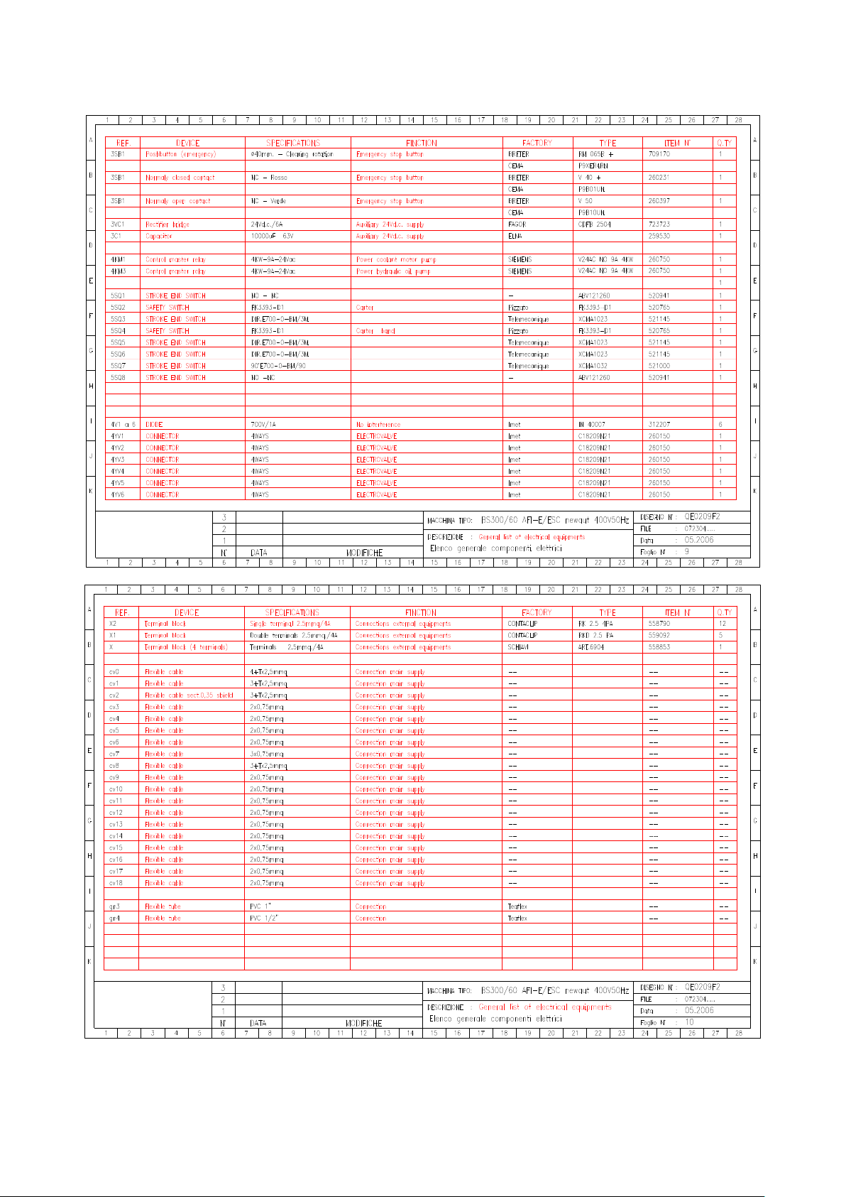
TRADUCTION OF THE ORIGINAL INSTRUCTIONS FOR USE
BS 300/60 AFI-E ED.2010 rev.00
44/61
++++++++++++++++++++++++++++

TRADUCTION OF THE ORIGINAL INSTRUCTIONS FOR USE
BS 300/60 AFI-E ED.2010 rev.00
45/61

TRADUCTION OF THE ORIGINAL INSTRUCTIONS FOR USE
BS 300/60 AFI-E ED.2010 rev.00
46/61
++++++++++++++++++++++++++++

TRADUCTION OF THE ORIGINAL INSTRUCTIONS FOR USE
BS 300/60 AFI-E ED.2010 rev.00
1/61

TRADUCTION OF THE ORIGINAL INSTRUCTIONS FOR USE
BS 300/60 AFI-E ED.2010 rev.00
2/61

TRADUCTION OF THE ORIGINAL INSTRUCTIONS FOR USE
BS 300/60 AFI-E ED.2010 rev.00
3/61

TRADUCTION OF THE ORIGINAL INSTRUCTIONS FOR USE
BS 300/60 AFI-E ED.2010 rev.00
4/61

TRADUCTION OF THE ORIGINAL INSTRUCTIONS FOR USE
BS 300/60 AFI-E ED.2010 rev.00
1/61
COD.
ITALIANO
ENGLISH
FRANCOISE
DEUTSCH
072302
BS 300/60 AFI-E NEWAUT
2VEL.V. 400 SEGATR (SARA' BS
300/60)
BS 300/60 AFI-E 3PH.2SPEED
SCIE A RUBAN
2VI.BS300/60AFI-E
113502
ALBERO X PULEGG.ANT.BS280
FRES ATO
BS 280 FRONT BAND WHEEL
SHAFT
BS 280 VORDERSCHEIBE
SAEGEARM
113517
ALBERO PULEGGIA
POST.BS280
BS 280 BACK BAND WHEEL
SHAFT
118842
ANELLO ANTIESTR.BRS230
CIL.PN. KS450/600/
BACK-UP RING BRS230
118932
ANELLO TENUTA OR 119
2,62X15,0 8
OR RING 2,62X15,08
119395
ANELLO TENUTA OR 159
3,53X55,5 6
OR RING 3,53X55,56
119576
ANELLO TENUTA OR3300
2,62X75,8 7
SEAL RING OR3300 2,62X75,87
119603
ANELLO TENUTAOR4250
3,53X63,09
SEAL RING OR4250 3,53X63,09
119621
ANELLO TENUTA OR 171
3,53X68,2 6
OR RING 3,5X68,26
119840
ANELLO TENUTA OR 6187
5,34X47
OR RING 6400 3,34X47
BOUCLE OR 6187 5,34X47
DICHTRING OR 6187 5,34X47
127810
ANELLO SEEGER A17 RIGA
RTD
SEEGER RING A17 RTD TABLE
128030
ANELLO SEEGER J22 SPAZZ.
BS350
SEEGER RING J22 / BS350
BRUSH
128116
ANELLO SEEGER J72
PULEGGE FORO 72
SEEGER INNER RING J72
BOUCLE SEEGER J72 POULIES
SEEGER INNERER RING J72
128702
ANELLO TENUTA 25X35X7
SEAL RING 25X35X7
128987
ANELLO
TEN.PARAP.BASL25X40X7
SEAL RING BASL 25X40X7
129107
ANELLO TEN.PARAP.BASL
55X70X8
SEAL RING 55X70X8 FOR
COUPLING
129736
ANELLO TENUTA 47X22X7
SEAL RING 47X22X7
131828
ARCO-RIDUTTORE BS300
LAVORATO
FRAME REDUCER BS300
132198
ARRESTO
POSIZIONAM.BS280/60
MECHANICAL STROKE-END
BS280/60
132828
ASTA COM.DISC.ARCO 280
SHE/SHI -E/VELOX SHE/AF
FEED CONTROL LEVER
BS280/VELOX
134120
ASTA DISC.TESTA/REGISTRO
MORSA D.20X400
FEED CONTROL/VICE STD
LEVER
TIGE DE BUTEE
136800
ASTA X RISCONTRO SCAR.280
AFI- E D.12
ROD FOR LENGTH STOP
280AFI D12
139993
AUTOAD.DISC.ARCO
BS300/60AFI-E (SU COLONNA)
STICKER SAW FRAME FEED
280AFIE
139995
AUTOADES.DISC.ARCO BS300
AFI-E (SU
COLONNA)MIS.628X107
STICKER DOWNFEED
SP.280NEWAUT
140295
BARRA CROM.40X788
AVANZAT.IMET LARGH.300/400
CON RETE PROTEZ
FEEDER CHROM.BAR 40X788
140299
BARRA CROM.40X807
AVANZAT.BS35 0/60
40X807 CHROM. BAR BS35
FEEDER
140423
BARRA
TRASMISS.AVANZ.NEWAUT
(NEW14)
TRANSMISS. ROD FEEDER
NEWAUT
153980
BLOCCHETTO GUIDA MORSA
FILETT. BS280/60
VICE THREADED GUIDE
154080
BLOCCHETTO GUIDA MORSA
FORATO BS280/60
VICE HOLED GUIDE
157210
BLOCCHETTO TENDINASTRO
280350 FRONTALE
BAND TENSIONER BLOCK
280350NEW
159988
BLOCCO MORSA BS280 AFI-E
(DERIVATA DA 280/60)
FIXED VICE ASSEMBLY
BS280AFIE
159990
BLOCCO MORSA BS280/60
MAN/SEMI AUT.
FIXED VICE ASSEMBLY
BS280/60
167248
BOCCOLA OTTONE D.20X30
BOW CYLINDER BRASSED

TRADUCTION OF THE ORIGINAL INSTRUCTIONS FOR USE
BS 300/60 AFI-E ED.2010 rev.00
2/61
CIL.ARC O 280S.AUT
WASHER
169467
BRACCIO X CILINDRO ARCO
280AFI -E
BOW CYLINDER ARM BS
280AFI-E
172190
BUSSOLA OTT.D8X15
BLOC.PIATTO PATTINO BS280
D8X15 PLATE BLOCKING BUSH
177257
BUSSOLA CONIC.TAPERL 110819 (PER PULEGGIA HTD TL385M-15)
TAPER BUSH 1108-19
177280
BUSSOLA D.16X25 PERNO
OSC.BS28 0
OSCILLATING PIN BUSH
D.16X25
179458
BUSSOLA
DISTANZ.D.6,5X10X14
SPACER D.6,5X10X14
179873
BUSSOLA CUSC.VITE
AVANZ.NEWAUT D.47X68
FEEDER BEARING SCREW
BUSH
179950
BUSSOLA FILET.TPN25 AVANZ
NC PROGRAM E NEWAUT
FEEDER THREADED BUSH
TPN25
179965
BUSSOLA MOLLE/ARCO 280GH BRUN
280-GH BUSH SPRINGS/BOW
179973
BUSSOLA X REGISTR.RULLO
NEWAUT (BS280-350)
BUNDLE
180055
BUSSOLA
DISTANZ.SPAZ.280/60 NC
- -
180342
BUSSOLA A SFERE 0658-240-40
CO MPACT STAR 40X52X60
BALL BUSH 0658-240-40
2 182476
BUSSOLA TENDINASTR.300350
NEWA UT
BAND STRETCHER BUSH
182946
CAPICORD.OCCH.11039112=6,5
X6 GIALLO BM 00331
184879
CARRELLO MORSA FISSA
BS280/60
FIXED VICE CARRIAGE
BS280/60
188051
CARRELLO HIWIN
HGW15CAZ0C X GU IDE
SENZA PRECARICO
HIWIN HGW15CAZ0C
CARRIAGE
- 188500
CARRO
INFER.AVANZ.BS350/60LAVO
RATO X NC
BS350/60
189861
CARRO SUPER.AVANZ.AFI-E
LAVOR. (MODELLI AFI-E)
FEEDER UPPER CARRIAGE
AFI-E
193523
CARTER CINGHIA
TRASM.NEWAUT. (NEW07)
BELT GUARD FOR NEWAUT.
BASE
201543
CARTER NASTRO-2PEZ.BS300AFINC SPAZZOLINO
TRASCINATO PULEGGI
BAND GUARD-2 PIECES- BS300
NC
205277
CENTRALIN.ARON 4
POS.COMPL+MOT
MONTARE:BS280/350 AFI-E
COMPL.HYDRAULIC UNIT
W/MOTOR
205860
CERNIERA ART.401-30-M6
BOTECO PER XT410
ITEM 40-30-MT6 BOTECO
HINGE
214700
CHIAVETTA 6X6X20 UNI6604
KEY 6X6X20
215123
CHIAVETTA 8X7X15 UNI6604
KEY 8X7X15 UNI6604
216270
CHIAVETTA 8X7X25 UNI6604
KEY 8X7X25 UNI6604
TL CLAVETTE ENTR.BAGUE
222755
CILINDRO MORSA KS450/600
80X10
VICE HYDR. CYLINDER KS450
SCHRAUBSTOCK
HYDR.ZYLINDER 450
222830
CILINDRO IDRAUL.ARCO 350
TIPO 50X140 AVVITATO
CYLINDER SHI D.50
227223
COLONNA NEWAUT.BS300/60
AFI-E (NEW01)
BASE FOR NEWAUT.
GRUNDLAGE NEWAUT
260163
CONNETTORE
4VIE+LED=S18209TC42 1
DIN43650A TRASPARENTE
4WAYS+LED CONNECTOR
4WEGE+LED VERBINDER
267454
COPERCHIO
VASC.REFR.BS300 NEWA UT
AFI-E
-
267523
COPRIAVANZATORE BS300
NEWAUT
FEEDER COVER NEWAUT 280
268253
COPRIFINCORSA ANT.NASTRO
BS280
BAND STROKE-END COVER
BS280
276674
CORONA BRONZ. M2,75 Z35
BS280
BRONZE WHEEL M2,75 Z35
BS280

TRADUCTION OF THE ORIGINAL INSTRUCTIONS FOR USE
BS 300/60 AFI-E ED.2010 rev.00
3/61
282758
CUSCINETTO 30204A 20X47X14
BEARING 30204A 20X47X14
283011
CUSCINETTO 32005X 25X47X15
BEARING 32005X 25X47X15
283102
CUSCINETTO 32008XA
40X68X19
CARRIAGE CONNECT.32008X4
40X68
284209
CUSCINETTO 6201.2ZR
12X32X10
BEARING 6201.2ZR 12X32X10
LAGER 6201 2ZR 12X32X10
284900
CUSCINETTO 6004.2RSR
20X42X12
CARRIAGE CONN. 6004EE
20X42X12
ROULEMENT 6004.2RSR
20X42X12
286020
CUSCINETTO 608.2ZR 8X22X7
BRUSH/PUMP CARRIAGE
CONNECTION
ROULEMENT 608.2ZR 8X22X7
286302
CUSCINETT.30305DJR
25X62X17/13 =310305A
BEARING 31305A 25X62X17/13
286795
CUSCINETTO 30305DR
25X62X15/13 = 30305A
CARRIAGE CONNECTION
25X62X15
ROULEMENT 30305A
25X62X15/13
288090
CUSCINETTO ASS.51103
17X30X9
BEARING 51103 ..X..X.
288725
CUSCINETTO 6206 30X62X16
CARRIAGE CONNECTION 6206
30X62
ROULEMENT 6206 30X62X16
288995
CUSCINETTO 6209 45X85X19
CARRIAGE CONNECTION 6209
45X85
291020
CUSCINETTO 6207.2RSR
35X72X17
CARRIAGE CONNECTION 6207
35X72
LAGER 6207EE 35X72X17
291304
CUSCINETTO 626.2ZR 6X19X6
PATTINI 280/300
BEARING 626.2ZR 6X19X6
294002
DADO ES.M4 BASS
AUTOBL.DIN985
HEXAGONAL NUT M4 DIN 980
SECHSKANTIGE MUTTER M4
DIN 980
294189
DADO ES.M8 BASS
AUTOBL.DIN985
ES M8 DIN980 NUT
296183
DADO M12 CAVE T CL.10
UNI5531 DIN508
NUT M12 FOR KEY T UNI5531
300745
DADO ES.M8 RIBASSATO
BRUNITO
HEXAGONAL NUT M8
303070
DADO ES.M10 UNI5588 6.S
BRUN.M
HEXAGONAL NUT M10 UNI5588
6.S
SECHSKANTIGE MUTTER M10
6.S
303845
DADO ES.M12 UNI5588 6.S
BRUN.M EDIO
HEXAGONAL NUT M12 UNI5588
6.S
304620
DADO ES.M12 UNI5589 6.S
BRUN.B ASSO
HEXAGONAL NUT M12 UNI5589
6.S
SECHSKANTIGE MUTTER M12
6.S
305080
DADO ES.M14 ALTO UNI5587
HEXAGONAL NUT M14
306120
DADO ES.M16X1,5 UNI5589 6.S
HEXAGONAL NUT M16X1,5
UNI5589
306500
DADO ES.M6 UNI5588 6.S
BRUNITO
HEXAGONAL NUT UNI 5588 6.S
ECROU M6 UNI5588 6.S
SECHSKANTIGE MUTTER M6
UNI5588
307720
DADO ES.M8 UNI5588 6.S
BRUNITO
HEXAGONAL NUT M8 UNI5588
6.S
ETAU ECROU POUR RENFORT
SECHSKANTIGE MUTTER M8
6.S
315285
DISCO REGISTR.VSF BS280
SCREW ADJUSTING DISC
BS280
322160
DISTANZIALE CORONA BS280
WHEEL SPACER BS280
325859
DISTANZIALE
GIUNTO/MOT.BS280
MOTOR COUPLING SPACER
BS280
327118
DISTANZIALE PUL.D.35X42
BS280
PULLEY SPACER D.35X42
BS280
SCHEIBE DISTANZSTUECK
D35X42
327176
DISTANZIALE
PULEG.AVANZ.NEWAUT
(NEW22)
NEWAUT PULLEY SPACER
30X20X41
327178
DISTANZIALE
TRASM.AVANZ.NEWAUT
(NEW21)
NEWAUT TRANSM.SPACER
30X20X17
330010
ESAGONO ATT.SPAZ.D100
BS350
HEXAGONAL BRUSH
CONNECTION
HEXAGONAL POUR BROSSE
D100
SECHSKANTIGER
BUERSTEANSCHLUSS
331524
EL.POMPA LUNGA AST60
PIEDE=150 230400V 1/2"W120=PMU60LP170
LONG ELECTRIC PUMP 230400
POMPE 331524
331925
FASCETTA TUBO TORRO S 1222/9 C7 W1
HOSE CLAMP W2 12-20
SCHLAUCHSCHELLE W2 12-20
349584
FLANGIA CHIUS.RIDUTT.BS280
REDUCTION CLOSING FLANGE
BS280
486448
GANASCIA CARR.MORSA
BS300/60 130X10X161
VICE CARRIAGE JAW
130X15X172

TRADUCTION OF THE ORIGINAL INSTRUCTIONS FOR USE
BS 300/60 AFI-E ED.2010 rev.00
4/61
UNIOFICATA
490803
GANASCIA
CHIUS.AVANZ.BS280AFIE
FEEDER CLOSING JAW
BS280AFIE
490852
GANASCIA APP.X
AVANZ.BS280AFI- E
FEEDER SUPPORT JAW
BS280AFI
492568
GANASCIA APPOGGIO DX
BS300/60 130X15X113
UNIFICATA
RIGHT VICE SUPPORT JAW
BS280/6
492611
GANASCIA APPOGGIO SX
BS300/60 130X15X162
UNIFICATA
LEFT SUPPORT JAW BS280AFIE
494604
GHIERA INTERNA
PIATTAFORMA BS2 80/60
PLATFORM INTERNAL
LOCKRING BS2
497110
GHIERA KM5 M25X1,5 PERNO
OSC.B S280
RING KM5 M25X1,5
497255
GHIERA KM8 M40X1,5 SIRIO
300
RING KM8 M40X1,5 BS340PR
500316
GIUNTO M24JUNIOR D.19X24
BS280
COUPLING D.19X24 BS 280
510200
GUARNIZIONE EL.POMPA
D.130X102 X2 GOMMA
ANTIOLIO
ELECTROPUMP SEAL
D.130X102
511144
GUARNIZIONE PARAP.AS40-505-8
ANTIDUST GASKET AS40-50-58
511163
GUARNIZIONE RS3240 CIL.
IDR.KS
PISTON SEAL RS3240
511290
GUARNIZ.IDROSTOP
DBM196133/M BS350/280
D50XD34X20.5
SAW FR.CYL.GASKET
MDB2X400501
511300
GUARNIZIONE LANTERNA
BS280 120 X80
GASKET BS 280
511330
GUARNIZIONE FLANGIA BS280
D.14 5X110
FLANGE GASKET BS 280 D.14
512497
GUIDA HIWIN HGR15R340C
BS300 (FORO 20MM!)
TASTATORE280/300
GUIDE HIWIN LGR15R340C
20/20
- 513095
IMPUGNATURA NERA 20X80
PLAST. X ASTA
PLASTIC BLACK HANDLE
D.20X80
515723
INDICATORE DIG.MIL.PAS5
GRIGIO DD52AN0005.0D/ELESA=CE.08625
POSITION INDICATOR MM5
PITCH
515753
INGRASSATORE M8 CH10
SFERA+MOL LA L1
OILER M8 CH10
515780
INSERTO SPECIALE D15.95X6.4
BS350
SPECIAL INSERT D15,95X6,4
PLAQUETTE SPECIALE
D15,95X6,4
515800
INSERTO QUADRO
SVAS.19,3X4 F.4
WXP0274=GATTIA191DB10.OD
C4.2G
SQUARE CARBURE PAD 19,3X4
F.4
PLAQUETTE CARBURE 19,3X4
F.4
VIERECKIGER EINSATZ 19.3X4
F.4
520765
INTER.SICUR.FK3393-D1
CHIAV.90 ° PIZZATO
SAFETY SWITCH FK3393-D1
520941
FINCORSA LEVA ABV121260
NAIS= OMRON D2VW5L1B1MBS-230
STROKE-END ABV161660
521000
INTER.FINCORS=TELEMEC.XC
MA1032 CAVO 2M,RUOTA
90°E700-0-BM/90
STROKE END SWITCH
TELEMEC.
FIN DE COURSE
521145
INTER.FINCORS=TELEMEC.XC
MA1023 CAVO 3M,RUOTA
DIR.E700-0-BM/3
STROKE END SWITCH
TELEMEC.
FIN DE COURSE
ENDSCHALTER TELEMEC.
XCMA1023
521580
LACCIO LEGRAND 320-32
2,4X180
LEGRAND PLASTIC STRING
521585
BASE A INCASTRO 320.76 X
LACCI LEGRAND
SUPPORT FOR STINGS 320.76
521691
LAMIERA X CAVI
AVANZ.BS300AFIE NEWAUT
SHEET HOLDER FEEDER
NEWAUT.
521718
LAMIERA FC CARRO AVANZ
NEWAUT. (NEW16)
NEWAUT. STROKE-END
HOLDER
521873
LAMIERA COM.EL.NEWAUT.
(NEW10)
EL.CONTROL SHEET METAL
NEWAUT.
521951
LAMIERA X
COOLANT DISTR.SHEET

TRADUCTION OF THE ORIGINAL INSTRUCTIONS FOR USE
BS 300/60 AFI-E ED.2010 rev.00
5/61
DISTRIB.REFRIG.BS280 SU
ARCO
METAL 280
522387
LAMIERA COPRI VITE
AV.NEWAUT
-
522924
LAMIERA "L" FERMO
TASTATORE
-
522941
LAMIERA TASTATORE BS300
-
523762
LANTERNA MOTORE BS280
FINITA
MOTOR/BOW STRAINER BS280
535032
MANIGLIA "U" NERA
ART.1102BOM8 =M243/140
BLACK HANDLE 1102BOM8
536585
MANIGLIA RIPRES.M12
FEMM.TIP80
TURNING HANDLE M12 TYPE
80
POIGNEE M12 TIP80
536675
MANIGLIA RIPRESA M12X45
TIP.80 MASCHIO
TURNING HANDLE M12X45
TYPE 80
POIGNEE M 12X45
DREHEBARER HANDGRIFF
M12X45 80
544666
MOLLA
COMPENSAZ.CUSC.D.62 MOT
SPRING WASHER DIA. 62
546938
MOLLA TAZZA 40X20,4X2,5
MANDRI NO/PULEGG.
SPINDLE CUP SPRING
40X20,4X2,5
RESSORT 40X20,4X2,5
SPINDEL FEDERRING
40X20,4X2,5
546957
MOLLA TAZZA 31,5X16,3X2
TENDIN AST.BS280
CUP SPRING 31,5X16,3X2
RESSORT 31,5X16,3X2
TELLERFEDER 31,5X16,3X2
546969
MOLLA TAZZA 25X12,2X1,5
CUP SPRING 25X12,2X1,5
TELLERFEDER 25X12,2X1,5
547652
MOLLA PER ARCO BS230-280350-3 40
SAW FRAME RETURN SPRING
340280
RESSORT RAPPEL ARCHET
BS340-BS
RAHMEN RUECKFEDER BS340BS280
590050
MOT.3F 2/4P FC90TP B5 V400
280 CE*1,7/1,3*B5 *SENZA
CHIAVETT
3PH MOTOR 2-4P FC90 V400 B5
6143976/10
NASTRO"280"2765X27X09
M42SVGLB (STB)DENTATURA
=6/10 HV950
BAND 2765X27X09 SVGLB M42
6/10
RUBAN "280" 2765X27X09 M42
616170
NIPPLO N4-4 1/4"A1/4" OTTONE
BRASS THREADED
CONNECTION M4-4
MESSING NIPPEL M4-4 1/4"
616230
NIPPLO OLIO 1/4"X3/8"BSP
RACC PER TUBO R6(CON
FEMMINA 3/8")
OIL THREADED CONNECTION
1/4
616517
OEL NIPPEL 1/4" X 3/8"
628489
PALETTA ARCOGIU FINE
TAGLIO (MACCHINE CON
TASTATORE)
STROKE-END PLATE BOW
DOWN
629273
PANNELLO
FRONT.COM.NEWAUT/TRON
FRONT PANEL FOR
NEWAUT/TRON
630632
PASSACAVO A MEMBRANA
DG9 D.15
DIAPHRAGM CABLE GLAND
DG9
630975
PASSACAVO SCATTO SB175022 NER O 145051
CABLE GLAND SB1750-22
631163
PATTINO ANTER.COMPLETO
BS280 N EW
FRONT BAND GUIDE BS280
VORD.BANDFUEHRUNGSCHUH
K.BS280
631165
PATTINO POST.COMPLETO
BS280 NE W
LOWER BAND GUIDE BS280
HINTERER
BANDFUEHRUNGSCHUH 280
631167
PATTINO
GUIDALAM.ANT.BS280 LAV
ORATO
FRONT BAND GUIDE BS280
VORDERER
BANDFUEHRUNGSCHUH
631168
PATTINO
GUIDALAM.POST.BS280 LA
VORATO
BACK BAND GUIDE BS280
HINTERER
BANDFUEHRUNGSCHUH
632788
PASTIGLIA D.10 OTTONE
BRASS. SPACER D.10
MESSING DISTANZSTUECK
D.10
651426
PERNO OSCILLANTE BS280 x
POTEN ZIOMETRO
OSCILLATING PIN FOR BS 280
654640
PIASTRA
ATT.CIL.AVANZ.NEWAUT.
(NEW17)
NEWAUT.FEEDER CYL. PLATE
657123
PIASTRA FRONT.MORSA
IDR.NEWAUT (NEW20)
VICE CYLIND. PLATE FOR
NEWAUT.
658305
PIASTRINA SLITTA MOBILE
AVANZA TORE
FEEDER MOVING PLATE
658310
PIASTRINA SLITTA MOBILE AFIE
MOVING SLIDE PLATE AFI-E
658324
PIASTRA TASTATORE BS300
APPROACHING PLATE BS280
BANDSPANNERFUEHRUNGSPL
ATTE
658340
PIASTRA
BAND TENSIONING GUIDE
BANDSPANNERFUEHRUNGSPL

TRADUCTION OF THE ORIGINAL INSTRUCTIONS FOR USE
BS 300/60 AFI-E ED.2010 rev.00
6/61
GUIDATENDINASTR.300350
FRONTALE
PLATE BS
ATTE
658663
PIASTRA TENDINASTRO
ANT.80X20 BS280
FRONT BAND TENS.PLATE
80X20
VORDERE
BANDSPANN.PLATTE 80X20
658678
PIASTRINA APP.PEZZO MORSA
280A FI-E
VICE PIECE SUPPORT PLATE
280A
661900
PIASTRINA X
FINC.PATT.INF.VTF NUOVO
PLATE FOR LOWER
BANDGUIDE VTF
661915
PIASTRINA FINC.NASTRO NEW
2XM3 10X2X35 BRUNITA
PLATE FOR BANDSTRETCHER
2XM3
661920
PIASTR.BLOCC.SPAZZOLINO
PLUS60 (BS280 PLUS 60
GRADI)
BRUSH LOCKING PLATE
BS280/60PL
673854
PIASTRINA FINCORS.CARRO
BS280 NEW-AUT.
BANDGUIDE STROKE-END
PLATE
673860
PIASTRINA
FINCORS.PATT.SUP.VTF 500
(LAMIERA)
BANDGUIDE STROKE-END
PLATE
674023
PIASTRINA RISC.
AVANZ.NEWAUT. (NEW13)
FEEDER STOP PLATE FOR
NEWAUT
687010
PIATTO SLITTA MOBILE
45X443X15 AVANZAT.IMET (2
PEZ. X CODICE
MOVING SLIDE PLATE
45X443X15
688448
PIATTO ATTACC.MOLLE BS280
BRUN
SPRINGS CONNECTION PLATE
BS280
688737
PIATTO 40X10X173 CIL/FRENO
BS2 80
CYLINDER/BRAKE PLATE
40X10X173
688802
PIATTO GUID.ANT.SCOR. 280
NEW
NEW SLID. BAND GUIDE PLATE
280
688820
PIATTO GUID.POST.FISSO 280
NEW
280 NEW FIX. BACK GUIDE
PLATE
695115
PORTAGOMMA PG8-4 D.8
INT.X1/4" DIRITTO
RUBB.HOSE CONNECTOR PG84 D.8
SCHLAUCHANSCHLUSS D.8
PG8-4
696080
PORTAGOMMA NYLON GES6
R1/8
NYLON RUBB.HOSE
CONNECTOR GES6
696346
PORTAGOMMA NYLON WES8
R1/2 GOM ITO
NYLON PUSH-ON CONNECTOR
R1/2 NYLON ANSCHLUSS R1/2 KNIE
697300
PORTA PLACCHETTE PATTINO
BS350
PAD SUPPORT FOR BAND
GUIDE 350
EINSATZLAGER FUER
BANDFUEHRUNG
699580
PORTA FINCORS/MOLLE
NASTRO 280 350 FRONTALE
BAND FRONT STROKE-END
HOLDER
BAND VORD. ENDSCHALTER
TRAGER
699591
PORTA FINCORS.ARCO FINE
TAGLIO (MACCHINE CON
TASTATORE)
STROKE-END HOLDER
NEWAUT
ENDSCHALTER TRAGER
NEWAUT
707195
PULEGGIA D.320X14
POST.BS280
BACK PULLEY D.320X14 BS280
707209
PULEGGIA D.320X72
ANT.BS280
FRONT PULLEY D.320X72
BS280
707313
PULEGG. HTD TL 38-5M-15F
CHIAR AVALLI X
NEWAUT300350
714785
QUADRO DERIV.REFR.ARCO
280AFIE
COOLANT JUNCTION BOX
BS280AFIE
716145
RACCORDO GOMITO G4MF=5020A1/4
ELBOW CONNECTION GAMF=5020A1
KNIEVERBINDUNG GAMF=5020A1
716823
RACC.OLIO DIR.D.6
1/4"CIL=E211 -106S
OIL CONNECTION D.6 1/4"
716834
RACC.OLIO DIR.D.8
1/4"CIL.E211 -108L
OIL CONNECTION D.8
1/4"CILE211
OELLEITUNG D.8 1/4" CILE 211
719061
RACC.OLIO GIR.D.8
1/4"CIL.E321 -108L=TN131
OIL CONNECTION D.8
1/4"CILE321
719073
RACC.OLIO DIR.D.6 1/8"CON.
OIL CONNECTION D.6 1/8"
719108
RACC.OLIO GOM.BSP F91-110
3/8- 3/8 (BS350 AFI-E)
OIL CONNECTION 3/8" F91-110
722345
RACCORDO T-4FFM-L=4050 DA
1/4"
CONNECTION T-4FFM-L=4050
1/4" 2 T-VERBINDUNG 4FFM-L 1/4"
725445
REGISTRO MISURA
ALLUM.+2VITI FORI D.20/12
ALUMINIUM LENGTH STOP
DEVICE
SUPPORT DIA 20
ALUMESSANSCHLAG + 2
SCHRAUBEN
727044
REGOLAT.IDR.ARON TIPO 2
COMPL. ALL.USO:BS280/350
SHIE+AFIE+N
CMP.UNIT SPEED REGULATOR
ARON

TRADUCTION OF THE ORIGINAL INSTRUCTIONS FOR USE
BS 300/60 AFI-E ED.2010 rev.00
7/61
727785
RIDUZ.OLIO 1/4"M-1/4"F
REDUCTION 1/4"M 1/4"F
REDUKTION 1/4"M 1/4"F
728542
RIPARO ANTER.NASTRO BS280
NEW
FRONT SAW BAND COVER
BS280 NEW
728560
RIPARO NAST.POST.280/60
NEW PA TTINO
BACK BLADE NEW COVER,280
NEW
728563
RIPARO NASTRO
POS.BS280/60 NEW
BACK BAND COVER BS280/60
NEW
732900
RISCONTRO REGISTRO
SCAR.PEZZI BS280 AFI-E
WORKPIECE OUTLET
ADJUSTAB.STOP
734694
RONDELLA RAME 1/4
COPPER WASHER 1/4
734698
RONDELLA RAME 1/8
COPPER WASHER 1/8
734745
RONDELLA ALLUMINIO 1-4
ALUMINIUM WASHER 1-4
ALU DICHTRING 1-4
735602
RONDELLA APPOGGIO
SS22X32X2 DIN 988 HRC45
SUPPORT WASHER SS22X32X2
AUFLAGE-FEDERRING
SS22X32X2
735755
RONDELLA APPOGGIO
SS30X42X2,5 DIN 988 HRC45
WASHER SS30X42X2,5
736000
RONDELLA
POLIURET.ARANCIO D.47 VITE
AVANZ.NC
WASHER D.47 BS340PR
737845
RONDELLA 35X12X6
SVASAT.BRUNIT
WASHER 35X12X6
741509
RONDELLA APPOGGIO
SS20X28X2 DIN 988 HRC45
SUPPORT WASHER SS20X28X2
RONDELLE VOLANT
SS20X28X2
DICHTRING SS20X28X2
741725
RONDELLA 35X9X5
SPIANAT.BRUN. VKS300/280
WASHER 35X9X5
742100
RONDELLA 35X8X5 BRUNITA
BURNISHED WASHER 35X8X5
SPEZIALUNTERLEGSCHEIBE
38X8X5
742282
RONDELLA 40X30X10,5
SVASATA (GREZZO =AVP D.40
BARRA)
WASHER 40X30X10,5
742333
RONDELLA 45X35X10,5
SVASATA
WASHER 45X35X10,5
RONDELLE 45X35X10,5
FEDERRING 45X35X10,5
742431
RONDELLA 35X10X6 BRUNITA
BURNISHED WASHER 35X10X6
744045
RONDELLA SPECIALE D.20X5
BRUN.
SPECIAL BURNISHED WASHER
20X5
RONDELLE D.20X5
SPEZIALUNTERLEGSCHEIBE
D.20X5
744500
RONDELLA APPOGGIO
SS9X15X1.2 DIN988 HRC45E
CILINDRI PN/IDR.
SUPPORT WASHER
SS9X15X1,2
DICHTRING SS9X15X1,2 DIN988
744550
RONDELLA APPOGGIO
SS13X19X1,5 DIN988 HRC45
AVANZAT.280AFIE
SUPPORT WASHER
SS13X19X1,5
AUFLAGE FEDERRING
SS13X19X1,5
744611
RONDELLA STAMPATA
5X15X1,2
PRINTED WASHER 5X15X1,2
744715
RONDELLA STAMPATA 6X18X2
PRINTED WASHER 6X18X2
GEDRUECKTER FEDERRING
6X18X2
744820
RONDELLA STAMPATA 8X24X2
PRINTED WASHER 8X24X2
744987
RONDELLA STAMP.12X30X4
BRUNITA
PRINTED WASHER 12X30X4
GEDRUCKTER FEDERRING
12X30X4
744998
RONDELLA STAMPATA
14X35X3
PRINTED WASHER 16X40X3,5
755801
RUBINETTO ART.6310 1/8"MF
(DISTR.REFRIG.280 AFIE)
COCK 6310 1/8"MF
HAHN 6310 1/8"MF
755888
RUBINETTO SFERA ART.400
1/4"FF FEM/FEM (ART.6300 -1/4FFAGNE
COCK ART.400 1/4" FEM/FEM.
759110
RULLO D.40X383 AVANZATORI
AFI
FEEDER SLIDE ROLLER AFI-E
759170
RULLO
AP.VERT.40x168+30xM12X20
NEWAUT
VERT.ROLLER FEEDER
NEWAUT
759501
RULLO GL/10 60Z C400 D10
S1,5 MOLLA
ACC.ZINC.(RULLIERE W40)
ROLLER GL/10 60HZ C400
D10S1,5
2
ROLLER GL/10 60HZ C400
D10S1,5
763200
RUOTA
TRASCINAM.SPAZZOL.BS350
BRUSH DRIVE WHEEL FOR BS
350
BUERSTE FUEHRUNGSRAD
FUER BS35
773023
SCIVOLO
SCARIC.COL.NEWAUT.280
(NEW08)
NEWAUT.BASE UNLOADED
SHUTE 280

TRADUCTION OF THE ORIGINAL INSTRUCTIONS FOR USE
BS 300/60 AFI-E ED.2010 rev.00
8/61
780850
SNODO UNIBALL SMG10 M10
MASCHI O
UNIBALL JOINT SMG10 M10
UNIBALL GELENK SMG10 M10
ZAPFE
785768
SPAZZOLA NYLON D.75x20
NYLON BRUSH D.75X20
BROSSE NYLON D.75X20
NYLON BUERSTE D.75X20
786162
SPIA OLIO HE45 PERFECTRECORD- 280 COD.12001
OIL SIGHT GLASS HE45
PERF/REC
PERFECT-RECORD BOUCH.
NIVEAU
OELSCHAUGLAS HE45
PERF/REC
792331
SPINA TENDINASTRO
BS300350 M12 D.16X290
BAND TENSIONING ROD
280350 NEW
VORDERER BANDSPANNER
STIFT
792823
SPORTELLO FISSO
DX.COL.BS300 A FI-E NEWAUT
FRONT FIX DOOR FOR BASE
NEWAUT
792845
SPORTELLO MOBILE COLON.
NEWAUT (NEW03)
FRONT MOB.DOOR FOR BASE
NEWAUT
796930
SQUADRETTA PORTA
REGOLATORE VE LOCITA'
REGULATOR SUPPORT PLATE
REGLER AUFLAGEPLATTE
798940
STAFFA BLOC.GUIDALAM
BS280 NEW
BS280NEW
BLOCK.BRACKETS.BLAD.G
851828
SUPPORTO GRUPPO
TASTAT.BS300
- -
851898
SUPPORTO GUIDA
TASTATORE BS300
855311
SUPPORTO X COPRIAV.BS280
AFI-E
FEEDER COVER SUPPORT
BS280AFIE
857136
SUPP/CHIOCC.AVANZ.LAVORA
T.AFIE
FEEDER LEADNUT SUPPORT
AFIE
863155
SUPPORTO SPAZ.SALDATO
300/60NC
- -
864381
TAPPO+DADO FIL.PG29 NYLON
PLUG+NUT PG29 NYLON
864623
TAPPO
OLIO+GUARN.1/2"CIL.=E336
FOSFATATO NERO
OIL TANK PLUG AND GASKET
1/2" VERSCHLUSSSTOPFEN 1/2"
864724
TAPPO OLIO+GUARN.1/4"CIL.=
OIL PLUG+GASKET 1/4"
865362
TAPPO+ASTINA ALS 2-18
PLUG+BAR ALS 2-18
910710
TARGHETTA GRAD.MORSA
BS280/60 (O°-60°)
VICE GRADUATED PLATE
BS280/60
918687
TASTIERA CONTR.TRON R20
10+10/ DAC CEB AU
EL. KEYBOARD TRON 10+10
928923
TESTATA
ANT.AVANZ.BS300NEWAUT
FEEDER FRONT HEAD
NEWAUT.
929031
TESTATA
POST.AVANZ.NEWAUT.AFNC
(SAW2++)
FEEDER REAR HEAD NEWAUT.
NC
929290
TIRANTE M10X95
CENTR.IDR.AFI-E
TIE ROD M10X95 AFIE
929312
TIRANTE M12X62 OTTONE
BS230
TIE RODS M12X62
929342
TIRANTE M12X115 MORSA
280AFI-E
TIE ROD M12X115 FOR VICE
280AF
933571
TUBO R6 3/8"
4500+FEMM.REC.3/8 " 350 AFI-E
TUBE R6 3/8"
933572
TUBO R6 3/8"
3450+FEMM.REC.3/8 " 280 AFI-E
TUBE R6 3/8" 3450
933625
TUBO R6 3/8"
1500+FEMM.REC.3/8
TUBE R6 3/8" 1500
933633
TUBO R6 3/8"
1200+FEMM.REC.3/8 " 280SHIE
TUBE R6 3/8" 1200
935500
TUBO RETINATO 8X14
ARIANNA
PLASTIC TUBE 8X14 ARIANNA
SCHLAUCH 8X14 ARIANNA
936245
TUBETTO GEMMA 8X12 = 80
GR/MT.
COOLANT HOSE 8X12
936359
TUBETTO GEMMA 6X9 = 45
GR/MT.
TUBE 6X9
936865
TUBO R7
1/4"4300+CODOL.d8:2DIR ITTI
KS450
TUBE R7 1/4" 4300
937711
TUBO R7
3/16"1330+CODOL.d6:1DI R/190°340
TUBE R7 3/16" 1330
941023
VASCA RACC.TRUCIOLI
NEWAUT.300 AFI-E (NEW04)
CHIPS CONTAINER NEWAUT.
BASE
955123
VITE TPN25
FEEDER POSIT.SCREW

TRADUCTION OF THE ORIGINAL INSTRUCTIONS FOR USE
BS 300/60 AFI-E ED.2010 rev.00
9/61
POSIZ.AVANZ.NEWAUT
(NEW12)
NEWAUT
956843
VITE TE M14X30 SIN.SVASATA
LEFT SCREW TE M14X30
VIS GAUCHE TE M14X30
957143
VITE MORSA BS300/60 AFI-E
NEWA UT
VICE SCREW FOR BS 280
NEWAUT
SCHRAUBSTOCK SCHRAUBE
NEWAUT
957156
VITE CHIUS.PINZA
AVANZ.NEWAUT BS300/350
AFI-E-NC
FEEDER VICE CLOSIN.SCREW
AFINC
VORSCHUBSCHRAUBSTOCK
SCHRAUBE
958928
VITE SENZA FINE BS280
ENDLESS SCREW BS280
SCHNECKE BS 280
961114
VITE REGOLAZIONE M24X2
XT410
XT410 M24X2 REG. SCREW
- 962390
VOLANTINO ART.751-32-M8X30
BS280
WHEEL 750-32-M8 BS280
962395
VOLANTINO ART.765-..-M12
BS230
WHEEL 765-..-M12
964234
VOLANTINO 19912520H7PFT-O
IMET FINITO
(PRECED.GE0016A6)
WHEEL 19912520H7PFT-O
HANDRAD 19912520H7PFT-0
T22930
CILINDRO AVANZ.AFI-NC
PREMONTA TO
FEEDER CYLINDER AFI-NC
FAST INSTRUCTION FOR USE OUR AUTOMATIC MACHINE
1- If the machine has not been installed yet, pls. read the 2 pages here attached (63LD in the
instruction manual).
In order to check that the electrical supply has been connected, push buttons16 or 17:
if the cutting unit moves up or down everything is OK; if nothing moves, disconnect and reverse two of the
wire in the plug.
(NOTE: if the emergengy button is pressed, nothing moves and the display shows "Er0020")
2 - This is a semiautomatic & automatic machine;
§ use keys 16 / 17 to move upwards the blade 10 mm about over the piece to be cut,
§ " " 16 / 17 to move downwards the blade below the piece to be cut
§ " " 16 to return in high position
3 - If you carry out well these regulations, it is possible that the machine starts to work in
SEMIAUTOMATIC cycle:
Push key 20 to make a simulated cut; if everything is OK , the cutting unit goes down fastly, slows down 10
mm over the piece, cuts and then goes up. It does not go up if the function F3 has been chosed.
It is better to make some cuts to check the cutting speed and others working conditions.
4 - Push together keys 4+25 to prepare AUTOMATIC CUT: if all is OK, button 25 flashes;
§ adjust the feeder stroke = unlock the lever under the digital indicator , turn the wheel until you read 501.5
(500 mm piece lenght + 1.5 mm blade thickness)* and close the lever
§ adjust the feeder vice = ( keys 4 and 18 = opening; 4 and 19 = closing)
§ select the number of feeder stroke = keep pushed key 26 and push key 11 or 13 to select : 1 for one
stroke; 2 for two stroke; 3 for three stroke; max. 29 stroke. Release key 26
§ select the number of pices to be cut = keep pushed the key 27 and push key 11 or 13 to select one by
one the quantity, or push key 14 or 15 to select hundred by hundred the quantity;. max. 9999 pieces. Release
key 27
§ zero-adjust the piece-counter = keep pushed key 25 and push key 12 to zero-adjust the piece-counter.
Release key 25.
* The above point is OK for 1 feeder stroke. In case of 2 feeder stroke you have to act as follows: piece
lenght divided into 2 + blade thickness divided 2.
In case of 3 feeder stroke you have to act as follows: piece lenght divided into 3 + blade thickness divided
into 3. And so on for 4, 5, 6, ...
5 - If you carry out well these selections, it is possible that the machine starts to work in AUTOMATIC
cycle:
Push key 20 to start the automatic cycle; if everything is OK the feeder moves backwards to take the
material an the key 20 flashes.
6 - Push again key 20 to start definitiverly the automatic cycle.
It is better to make some cuts and verify the lenght of cutted pieces in order to correct it by the
length regulator .
NOTE : when the bar ends, the program returns to semiautomatic cycle.

TRADUCTION OF THE ORIGINAL INSTRUCTIONS FOR USE
BS 300/60 AFI-E ED.2010 rev.00
10/61
You have to take out the rest piece, replace the new material, cut the initial scrap of the bar, and after return
to the automatic cycle by pushing keys 4 + 25 . Operate as indicated to point 5.
If more that 10 minutes passes before any key is pushed( and machine is not running) the electronic control
switch-off the motor of the oil hydraulic unit. To switch-on the motor again, push key 19 the display shows
for one second a serie of flashes.
ER0001 error in the configuration EEPROM
ER0002 error in the data checksum in EEPROM 1 1st. block
ER0003 error in the data checksum in EEPROM 2 2nd. block
ER0004 error in the data checksum in EEPROM 3 3rd. block
ER0005 error in the saved data in the permanent memory
ER0020 emergency active (emergency pushed?)
ER0021 motor overload protections (overheated motor?)
ER0022 open carter
ER0023 broken band
ER0024 FREE
ER0025 blocked inverter (motor under stress?)
ER0026 too high motor absorption
ER0027 not correct position of the tool for starting the cutting cycle (blade locked in the workpiece?)
ER0028 vice pressure problem (vice too open/oil pressure?)
ER0029 blade unblocking -for SIRIO models onlyER0030 bar end - in automatic cycle - (end of the material?)
ER0031 carriage not in correct position - for starting the automatic cycle -
ER0032 feeder vice (vice too open/closed?)
ER0033 piece counter selection on 0 (for automatic cycle)
ER0034 OIL PUMP DEACTIVATED - for hydraulic models –
ER9999 overflow in the machine timer (it is necessary to switch the system off and then on).
 Loading...