

IMET SIRIO 315, SIRIO 315 SH User Instructions
TRADUCTION OF THE ORIGINAL INSTRUCTIONS FOR USE
SIRIO315+315 SH eng ED.2011 rev.00 1/41
IMET Spa
Loc. Tre Fontane - Cisano Bergamasco
Tel. 035/4387911 - Fax. 035/787066
Web site: www.imetsaws.com
E-mail: imet@imetsaws.com
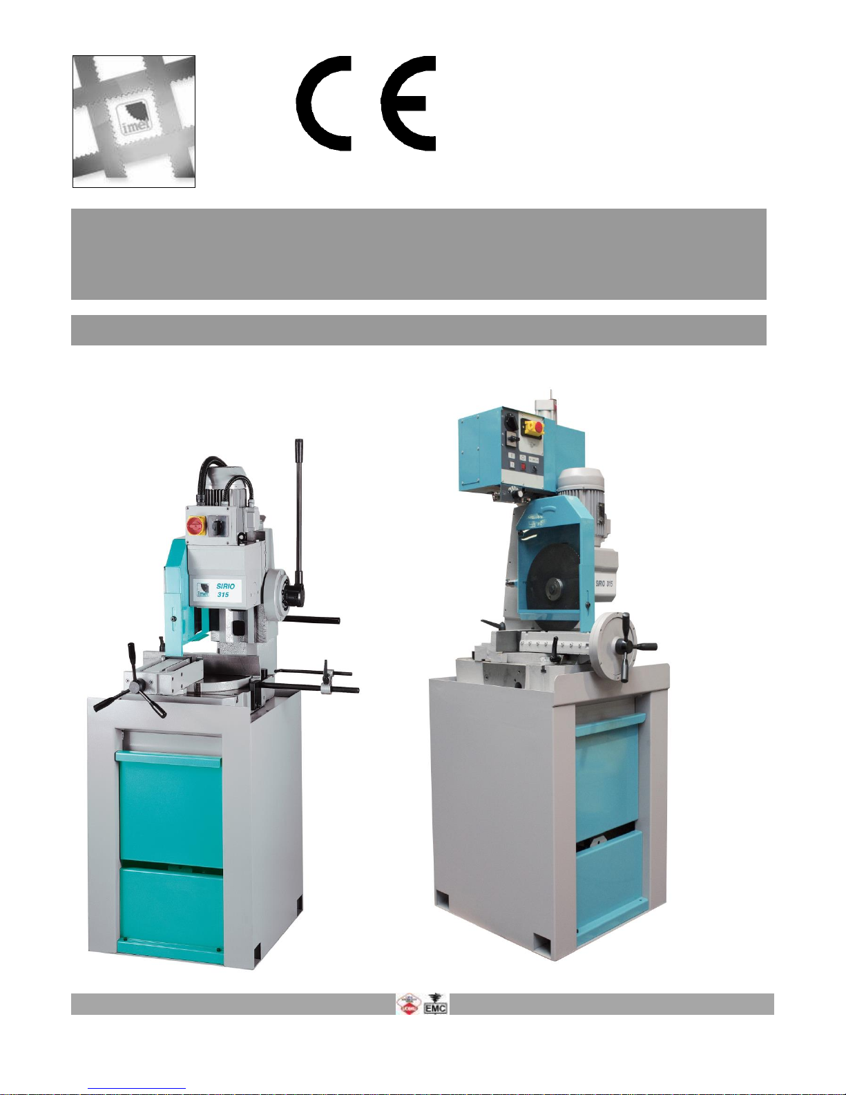
Metal Cutting Circular Saw with vertical column :,
manual type SIRIO 315,
semiautomatic–hydropnematic type Sirio 315 SH
USER’S INSTRUCTIONS

TRADUCTION OF THE ORIGINAL INSTRUCTIONS FOR USE
SIRIO315+315 SH eng ED.2011 rev.00 2/41
1We recommend to read carefully the information here included in order to install, use and maintain correctly and
safely this machine.
Please refer always to this instruction manual in case of assistance service need and keep it carefully for all the
machine life. The reference number in Italy is +39 035 4387918 or +39 035 4397928.
A consequence of the continuous improvement of the product is that some images/descriptions here included could not
correspond to the improved features of the machines.
Your kind collaboration would help us in intevening asap.
In the enclosed Compliance Declaration you will find the Safety and Reference Norms applied during the planning and
construction of this machine.
The choice and the use of the parts have been made by considering the conditions of use and the long machine life.
The identification plate, with the serial number, is fixed on the front right angle of the base or on a wall of control box.
1.1 - ATTACHED DOCUMENT FOR E.M.C. ( INDUSTRIAL ENVIRONMENT)
The user is responsible for installation and use of this machine in compliancewith the manifacturer's
instructions shown in this manual. This plant meetsthe protection requirements in accordance with the
Directives2006/42/EEC,
And 2004/108/EC as for electromagnetic compatibility (EMC).
In particular, it follow the technical instructions of the Rules EN55011,EN50082-2 and it has been realized
for industrial and not for household use.
In the event that should be electromagnetic interferences the user is responsible for solving the problem
together with the technical assistance of the manifacturer.
Before installing the machine the user must take into account possible electromagnetic problems of the
working area. In particular, we suggest installing the plant away from:
-signalling, control and telephone cables; -radiotelevision transmitters and receivers;
-computers or controlling and measuring instrument; -safety and protection devices.
The electric supply cable must be kept as short as possible, well right and without wires.
The covers, the door and the frame must be suitably closed when the plant is operating.
Under no circumstances the plant must be modified except for adjusting and changing established by the
manifacturer. Follow the maintenance schedule

TRADUCTION OF THE ORIGINAL INSTRUCTIONS FOR USE
SIRIO315+315 SH eng ED.2011 rev.00 3/41
2
===========================================================================
CE DECLARATION OF CONFORMITY (encl. II A DIR 2006/42/CE) / 02
===========================================================================
THE MANUFACTURER : IMET S.p.A
Località Tre Fontane
24034 - CISANO BERGAMASCO –BG- ITALIA
HEREBY DECLARES THAT
in designing and manufacturing the machine described here below , we have considered the most important
requirements of safety and health dictated by the European Directives of the Machine Security. Remember that this
declaration loses its validity if machine is modified without our agreement.
Trade name CIRCULAR SAWING MACHINE FOR METALS
Code / Model / Type
Manufacturing year
Serial number
IT IS IN COMPLIANCE WITH THE DIRECTIVES
DIRECTIVE 2006/42/CE OF THE EUROPEAN PARLIAMENT AND OF THE COUNCIL OF THE
17TH/05/2006 REGARDING THE MACHINES AND THAT MODIFIES THE DIRECTIVE 95/16/CE;
DIRECTIVE 2004/108/CE OF THE EUROPEAN PARLIAMENT AND OF THE COUNCIL OF THE
15/12/04 REGARDING THE ELECTROMAGNETIC COMPATIBILITY -EMC-
DIRECTIVE 2006/95/CE OF THE EUROPEAN PARLIAMENT AND OF THE COUNCIL OF THE
12/12/06 REGARDING ELECTRICAL EQUIPMENT FOR USE OF LOW VOLTAGE -LVD-
HARMONIZED STANDARDS REFERENCE EN.12100-1, EN12100-2; EN 55011, EN50082-2, EN 13898, EN 60204
LEGISLATIVE DECREE N.17 OF THE 27TH OF JANUARY 2010.
AND AUTHORIZING THE PERSON LISTED BELOW TO ISSUE THE TECHNICAL FILE.
Date : 01.01.2010
The signatory identification The manager
Angelo Meroni
-------------------------------------------------------------------------------------------------------------------------File : Machine no. Delivery note no Dated
---------------------------------------------------------------------------------------------------------------------------
The original is at the machine
………………..
………………..

TRADUCTION OF THE ORIGINAL INSTRUCTIONS FOR USE
SIRIO315+315 SH eng ED.2011 rev.00 4/41
3 - MACHINE NOISE
The decibel pointed out in the workplace in the conditions under described is appointed to the simoultaneous working
of some machine parts in motion ( it depends on the detailed cycle ) added to that one of the tool when is cutting the
workpiece.
In several moments the decibel are pointed out to note the different using conditions.
The phon-meter is placed at about 1 meter near the machine and at about 1,60 m from the floor.
The results of each test is in dBA and they mean the average of 3 tests made from the: left side, opposite side,
right side.
For any machines the using conditions are the following :
When idle, at the maximum blade speed: dBA 67
During the cut, at a suited blade speed, cutting solid steel (St12=≈C20, 80mm diameter): dBA 74
(tolerance ± 2dB).
In the standard production the test is made by a same machine of above mentioned one, in compliance with E.C.
safety norms 89/392/CEE and 86/188/CEE .
The use of the machine in bad conditions or the use of the wrong tools cause also sensitive alterations of these tests
and it is prejudicial for the health of the taff and for the good results of the work .
Most of all the noice depends on the cutting material, on its sizes and on the locking system.
By expecting that above mentioned decibels could be exceeded, we recommend the operator the using of the personal
means of protection ( head phones, plugs etc. ) in case of working a long time at highest levels, taking into account
other possible machinery running nearby and the characteristics of the working place
3.1 - ADDITIONAL HEALTH AND SAFETY REQUIREMENTS
This type of machine, manually controlled during some working operations, must respond to further health and safety
requirements as specified by article 2.2 of the Annexed I of the European Directive 2006/42/EC.
In particular, the level of vibrations emitted by the machine while in use must be clearly specified in the instructions.
This machine does not emit vibrations of a level higher than 2,5 m/s 2
The measurement procedure used conforms to the general norms applied to this type of machine.
As in the preceding paragraph, using the machine in unsuitable conditions or using the wrong tools can
cause changes affecting this value, endangering the health of the work force as well as the quality of
production.
Vibrations emitted during cutting may be amplified by the material, by its dimensions and its
positioning/clamping in the vice.

TRADUCTION OF THE ORIGINAL INSTRUCTIONS FOR USE
SIRIO315+315 SH eng ED.2011 rev.00 5/41
4 - GUARANTEE NORMS
I.ME.T. offers a wide range of sawing machines and accessories, destined to who buys/uses them as part of a
commercial or professional activity.
The manufacturer grants that this product has been strongly controlled and that there are no defects in the used and
working materials for a period of 12 months from the date of the delivery note.
The italian law D.L. n° 24 issued on 02/02/2002 and valid since 23/03/2002 (which carries out the European Directive
1999/44/CE) indicates different terms only for convenience products for private use.
If the user points out some defects to the manufacturer during the warranty time, the manufacturer will replace the
components that are considered defected.
In case of reparation of the machine during the warranty time the shipment will be accepted only if the delivery is Free
Destiny (that is the freight costs are supported by the owner of the machine), and the return of the machine to the
customer is considered EX WORKS.
If the manufaturer is not able to remplace a component within an acceptable time, both companies (manufacturer and
user) will reach an agreement for satisfying completely the needs of the user.
The a.m. warranty is not valid in case of accidental damages, or defects provoked by a wrong use of the machine or
maintenance, by variations made on the machine, or by the use of the machine in a place not corresponding to the
indicated enviromental specifications.
4.1 - The manufacturer does not offer further warranties, written or spoken, explicit or implicit of its products and does
not offer implicit warranties on saleability or adequacy for particular uses not foreseen by the agreement.
The a.m. limitations and exclusions can also be not applicable in Countries, where there are no implicit limits of
warranty time on the products. Anyway each implicit warranty is limited to a time of 12 months from the date of the
delivery note.
4.2 - The date of manufacture, deducible from the serial number placed on the machine, is a very necessary reference
for the warranty, for the assistance after-sale and for the identification of the product.
Each tampering on the products, expecially the installation of safety devices, will relieve the manufacturer of any kind of
responsability.
The parts most subject to rapid and continuous wear are not included in the warranty (for example: transmission belts,
gaskets, oils, blades, and so on).
For the electrical, electronic and hydraulic equipments and for the other equipments having its own individuality (of
which there is the possibility to know the name of the constructor), the manufacturer gives to the user the same
warranty received by the primary constructor of these parts.
4.3 - The components replaced during the assistance operated by the manufacturer have a warranty of 6 months
from the installation date indicated on the Technical Service paper, one copy of which is given to the owner.
Date of purchase…………………….. ………………….
Date of installation………………… ………………….
Name of Supplier………………………….. ………………….

TRADUCTION OF THE ORIGINAL INSTRUCTIONS FOR USE
SIRIO315+315 SH eng ED.2011 rev.00 6/41
5 - SUMMARY pag.
1- PREMESSA 2
2 – CONFORMITY DECLARATION 3
3 – AIR NOISE 4
4 – GUARANTEE NORMS 5
5 – Index 6
6 – Technical characteristics 7
7 – Installation – minimum requirements 9
8 – Moving and transit 9
9 – Fittings/optionals 11
10 – Blade choice 12
11 – Foreseen use and controindications 14
12 – Machine description 17
13 – Work preparation 18
14 – Blade mounting 19
15 – Functioning 20
16 – Regulations 25
17 – Maintenance – for the user 27
18 – Band running-in 28
19 – Machine running-in 28
20 – Draining of used/produced substances 29
21 – Trouble-shooting 29
22 – Machine demolition 31
23 – Spare parts 32
24 – Maintenance – for qualified technicians 33
Electrical drawings
Hydraulic diagram
Spare Parts drawings
TRADUCTION OF THE ORIGINAL INSTRUCTIONS FOR USE
SIRIO315+315 SH eng ED.2011 rev.00 7/41
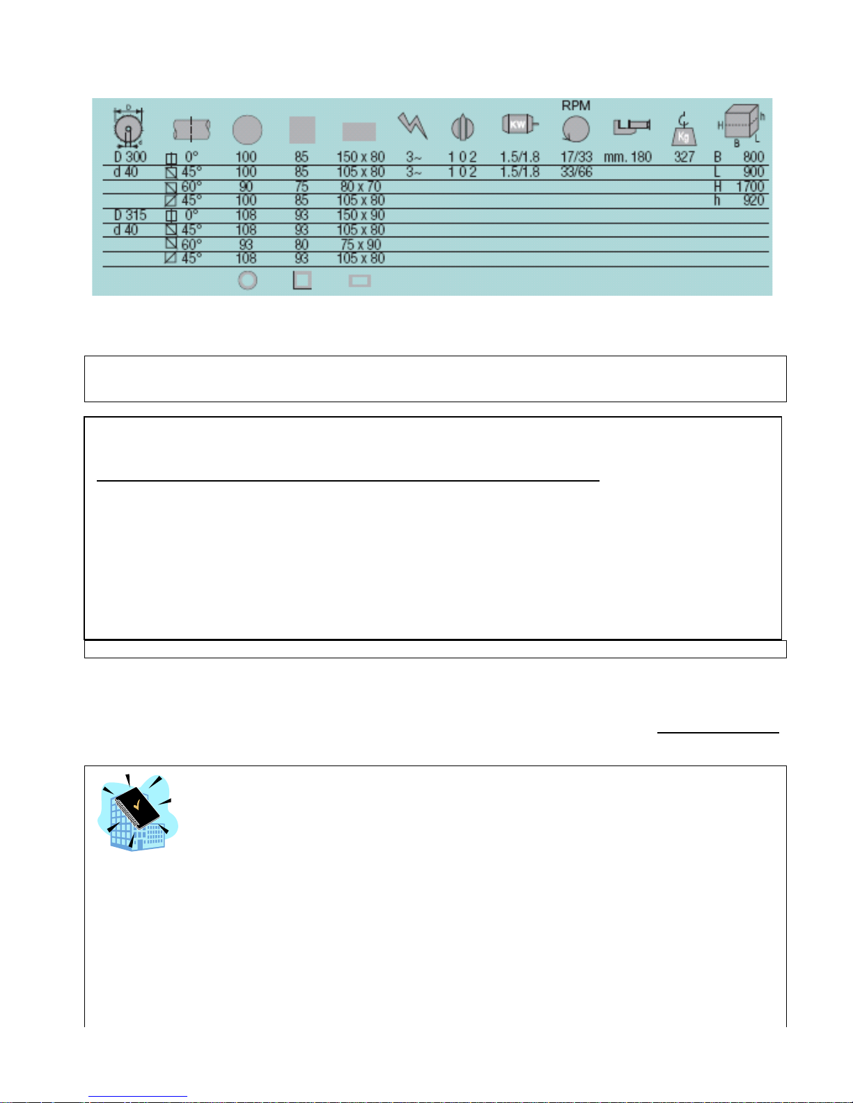
TECHNICAL DETAILS and CUTTING CAPACITY in mm *
* WARNING: The maximum cutting capacity refer to profile sections, for the cut of solid the cutting capacity are
reduced. For further details please contact our sales department.
- Segatrici a disco a discesa verticale per tagli da 0° a 45° destra e da 0° a 60° sinistra
- Adatte per pieni e profilati in acciaio anche ad alta resistenza
-
The head swivels from 45 deg. right to 60 deg. Left, sliding on vertical adjustable dovetail guides. Final
reduction in oil bath, bronze wheel with large diameter and primary tramsmission by hardened gears.
Suitable for cutting metal profiles and solids, high resistance too.
ATTENTION: only to be used with saw blades with hole of 40 mm dia
STANDARD.EQUIPMENT:
Electrical components complying with E.C. Standards EN60204-1, EN55011, EN50082-2; Main switch
with interlocking attachment and minimum tension coil, thermic overload motor protection, emergency
button,
Front adjustable pneumatic vice free to slide transversally on the worktable with quick blocking,
adjustable anti-bur device, fast and positive location at 0 and 45 degrees left by mechanical strokeends.
. Floor stand with removable chip tray tank, coolant pump, adjustable bar stop.
Wrenches and manual of instructions, maintenance and spare parts
ATTENZIONE: LA SEGATRICE È FORNITA SENZA LAMA
Le specifiche tecniche riportate in queste tabelle servono ad una valutazione generale della macchina e delle sue
possibilità'.
Se non indicato diversamente, tutti i dati riportati in questo manuale sono riferiti alla Versione Standard,
idonea per funzionare a 400 V / 50 Hz TRIFASE,
7 - INSTALLATION
The machine can work according to the parameters provided by the manufacturer if it is rightly installed and the
minimum requirements are observed, as follows :
- Machine must be used indoor and with temperatures from +5 to + 40 ° C.
- The relative humidity of the environment must not go over 95%.
- The nominal value of the voltage of electric energy must be between + - 10 and the frequency of the nominal value
must be between + - 2%.
The floor must have good characteristiques of capacity and level.
Floor space, operator position and working area are indicated in the included drawing that concerns the machine only
without fittings as optional.
Work table must be leveled: by using the screws and nuts (NOT SUPPLIED) put in the little feet holes to FIX the
machine to the floor .
TRADUCTION OF THE ORIGINAL INSTRUCTIONS FOR USE
SIRIO315+315 SH eng ED.2011 rev.00 8/41
The included electrical schemes reproduces the necessary details to arrange the connections, to be
predisposed for 4 KW power request,.
. Earthing of all the electric parts with a dedicated GREEN/YELLOW wire, connected with a TN system to the supply
cable. A supplementary earthing point – indicated with PE – can be located on the metallic structure of the machine.
N.B.
Be careful with cables protruding from upper part of machine when you are lifting it.
Fix between them the machine and the floor stand by using the 4 socket screws supplied together to the current
fittings ( do not use those employed for the packing ). The nuts are already in the using position.
The tank and the electropump must be desplaced from the base and placed inside the floor stand trough the back
opening; to do this , it is necessary to remove the chip tray taking out it from the front side of base and the front lower
panel.
The cables that come out from the back side of the machine must be inserted in the floor stand; then the supply cable
must be inserted ( form inside to outside ) in the cable-nut ( and locked ) before the connection to the line.
Connect the cooling pipe to the cock placed on the carter of the machine.
7.1 - DIFFERENTIAL PROTECTION
For the connection of the differential protection on the power supply line it is necessary to use switches with
a threshold of interference on the power dissipation of not less than 300 mA (size 0.3 A or higher is
recommended), having possibly time adjustment availability (0>1.5 sec).
E.M.C. Electromagnetic noise
This machine has been foreseen for industrial and not for household use. In the event that should be electromagnetic
interferences the user is responsable for solving the problem together with the technical assistance of the
manufacturer. Before installing the machine the user must take into account possible electromagnetic problems of the
working area. In particular we suggest to install the plant away from:
- signalling, control and telephone cables;
- radiotelevision transmitters and receivers;
- computers or controlling and measuring instruments;
- safety and protection devices.
The electric supply cable must be kept as short as possible, well right and
without wires.
The covers, the door and the frame must be suitably closed when the plant is operating.
Under no circumstances the plant must be modified except for adjusting and
changing established by the manifacturer. Follow the maintenance schedule.
8 – TRANSPORT & LIFTING
For the transport of the machine only the methods indicated below are possible. However, be sure that the means of
transport snd lifting are able to stand the machine's weight and its packing (about 500 Kg):
WARNING
The personnel in charge of loading, unloading and moving the machines should use protective gloves.
WARNING
When lifting or moving the machine, or a part of it, take care of clearing the operations area of the people, considering
also an appropriate safety area around it, so as to avoid any risks of injuring people or damaging things located nearly.
Special packings – wooden crate , wooden case –may be predisposed on request, by charge.
ALL THE OPERATIONS THAT INVOLVE MOVING THE MACHINE MUST BE CONDUCTED WHILE RESPECTING
THE FOLLOWING BASIC RULES:
+ When moving the machine, an appropriate means has to be used, with a loading capacity higher than the weight
to lift, which is indicated on the machine.
+ When choosing and then using equipment such as ropes, chains or lifting belts, be careful about their geometry
during the lifting and about the consequent actual loading capacity.
TRADUCTION OF THE ORIGINAL INSTRUCTIONS FOR USE
SIRIO315+315 SH eng ED.2011 rev.00 9/41
+ The machine is structured so as to offer lifting points, which are appropriately indicated and will have to be used
for lifting it.
+ In case the lifting belts touch parts of the machine, nylon belts are required; ropes or chains wrapped with jute or
clean covering can also be used. A great care is necessary while slinging and moving the machine in order to
hinder damages.
+ All operations have to be conducted with graduality, so as to avoid jolts and dangerous situations.
+ The person in charge of the operations has to make sure that all the national, local and company norms in
reference to injury prevention and work safety are respected.
+ Onr or more areas for material storage have to be identified.
After unpacking , unscrew the 4 screws of the fixing feet near the base of the machine unit.
Use the iron plate or the lifting rope already fixed to the highest part of the machine to lift it up.
The weight is shown on the packing outside and in the technical data of this manual book also -see par.2- ( it concerns
the total weight : only the floor stand weight is 100 kg. about).
Be sure that lifting tools are proper for the weight and that the moving is correctly made without unbalancing the
machine.
In case of following manipulations, the machine should be displaced with the saw frame completely down and fixing the
turntable to avoid rotations of the parts. Do not use the control box to lift the machine up. Desplace the machine from
floor stand in case of instability.
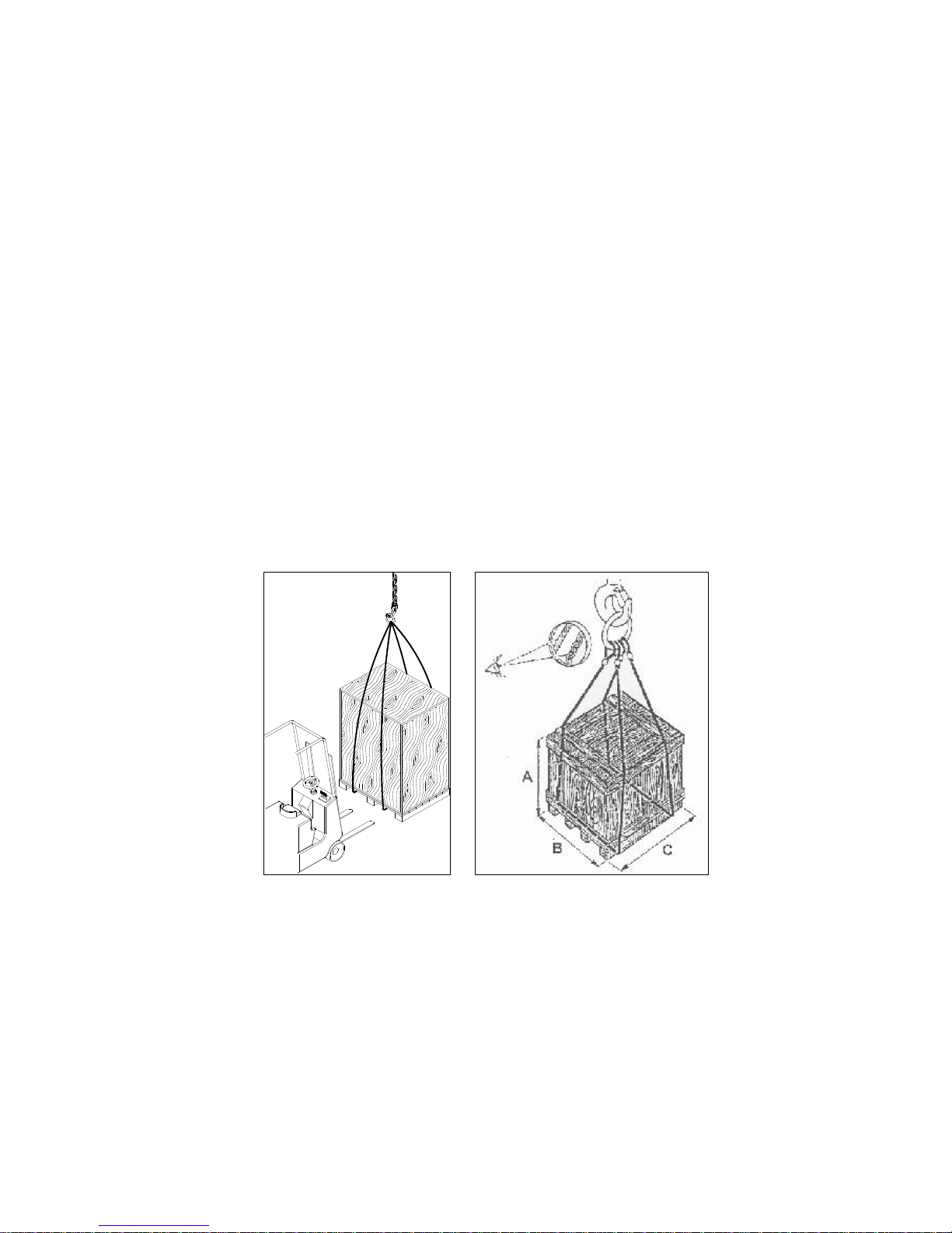
Transport with wooden crate or wooden case. ( BY REQUEST , ON CHARGE )
The machine is wrapped with thermoplastic material in order to assure a suited protection of all its parts; then it is
packed into a wooden crate or cage to protect it from collisions, inclement weather and so on.
To lift it, use a forklift from front side of machine, with forks length 1.0 m or more .
You need to follow the indications you find on the packing before proceeding to moving or opening it.
WARNING The size of the packing varies according to the machine ordered and its configuration.
WARNING
The machine is fixed to the packing by means of screws, so as to hinder that it can move during the transport
TRADUCTION OF THE ORIGINAL INSTRUCTIONS FOR USE
SIRIO315+315 SH eng ED.2011 rev.00 8/41
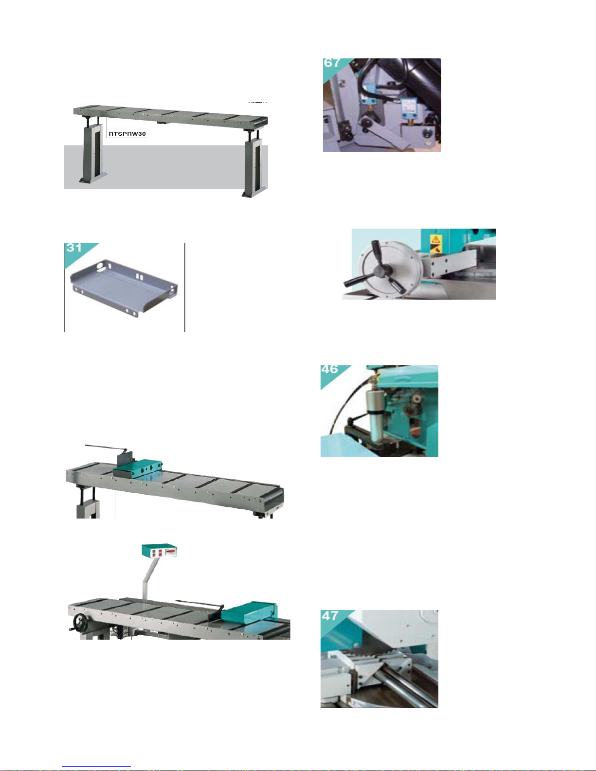
9 – FITTINGS / ACCESSORIES
Supporting roller tables: for installing these
accessories in the right way it is necessary first of all to
level and fix the machine.
These can be connected on both sides (loading /
unloading). By a proper connection kit , RASIRU , as
OPTIONAL.
Take as reference point the worktable and the support
back jaw in order to aligne the roller tables starting
from the one that is nearest to the machine. If you
need very long pieces fix the legs of the roller tables
on the ground and recycle the coolant transported by
the workpieces that have to be cut.
If your working process require it, on the unloading side
you can choose to use the roller table with manual
measuring system (RTM)
or the one with digital measuring system (RTD) also.
This last have to be synchronized to the machine
control-that gives automatic desplacement of material
stop plate- by the plug: 000910 as OPTIONAL,
specifiing the machine version.
Pneumatic front vice –STANDARD ON THE MODEL
315 SH- by request only for manual model- by the
standard furniture the opening / closing system is
synchronized to the up / down movement of the gear
head. The locking cylindre comes out a stroke of 5 mm
about. For retrofitting ask to the Service Assistence.
Vertical pneumatic vice - It is connected directly to
the line that goes to the frontal vice and it allows to
lock the piece also from the upper side. It is
recommended to cut more pieces when you put them
side by side on the working table.
" V " jaws - necessary to rightly lock the pipes until 85
mm. of diameter by avoiding the deformation. They
allow to increase the penetration speed by reducing
the working time .They can only make you cuts at 0°,
minimum length of cutting piece is 35 mm.
Make the holes, if necessary, by using the template
included in the assembling kit (only if supplied after
selling) ; assemble them by following the instructions
and place them into line by using for example a straight
round, to guarantee a right passage of the bars.
During the cut they are progressively shaped by the
blade: if your working process don’t require a complete
cut, leave them attached one to the other.
TRADUCTION OF THE ORIGINAL INSTRUCTIONS FOR USE
SIRIO315+315 SH eng ED.2011 rev.00 9/41
Standard adjustable bar stop - fixed on the right side,
it is necessary to make more cuts with the same
lenght.
Voltage transformer - set it between the electric
equipment of the building and the electric supply of the
machine. It allows to work with a different voltage than
the standard one (that is 400V ). Available voltages are
230V, 460V , 500V, 575V.
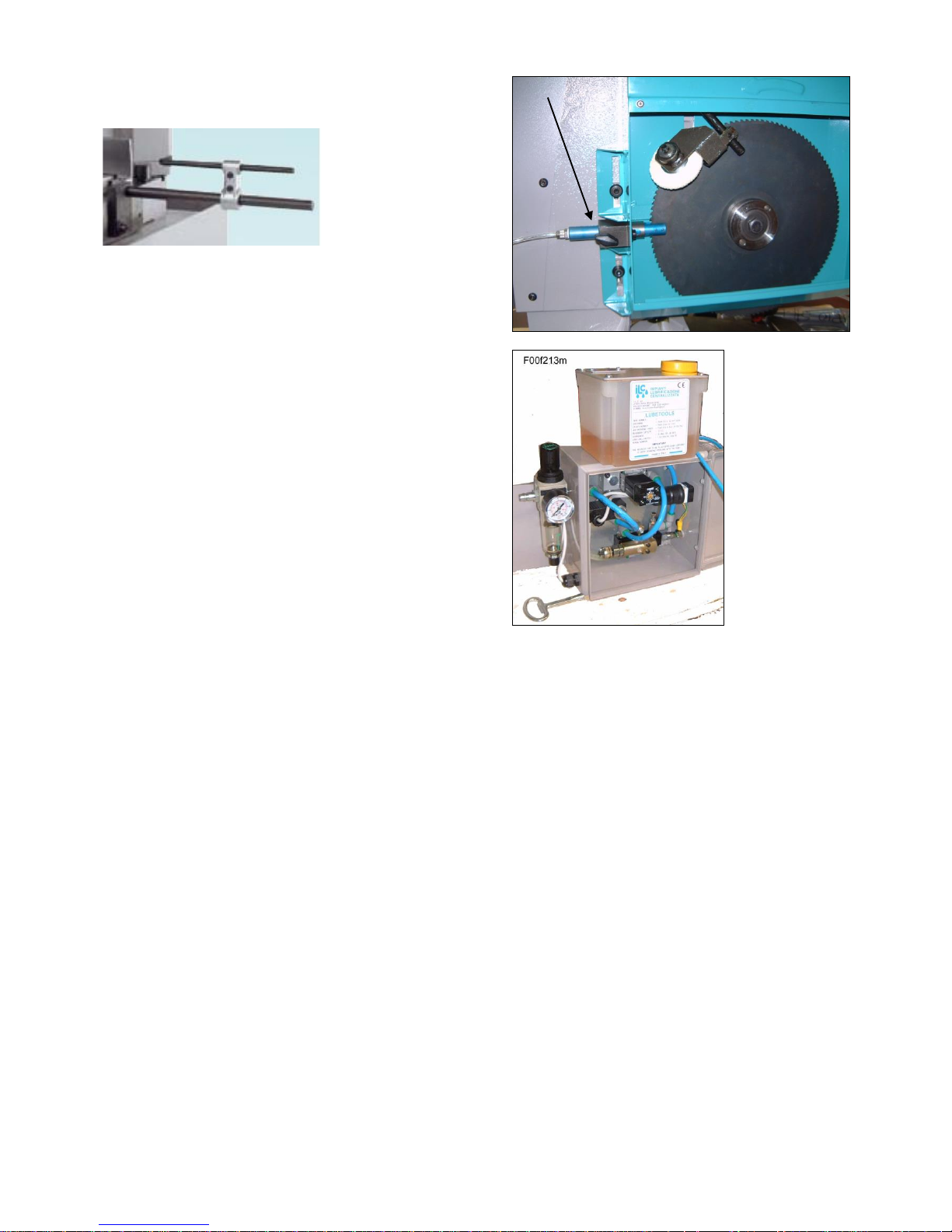
Minimal lubrication system – This device, applied to
the saw, allows to eliminate almost completely the
traditional coolant system, keeps the material much
cleaner and avoids to waste cutting oil and water. It
works only during the cut.
It is comprised of a PIN-nozzle –as shown by the arrow
- with 3 micro-holes, a tank with devices to adjust the
quantity of oil and the air pressure. The switch of the
electric system - working with low tension 24V AC (or
230 V AC on manual model) allows to turn it off at any
moment and use the normal coolant system.
It works with air supply connection, about 4/6 Bar.
Note :This picture is referred to a SIRIO 370 model
10 - BLADE CHOICE
In this paragraph we suggest the type of blade to use for cutting and the material that must be worked. To get the best
performance from this machine it is necessary to understand the right applications of the used tools and what you have
not to do with them.
The blade you have to use must have the following dimensions (in mm.):
external diameter = 315 max./300 min.
hole dia. 40 ; thickness = from 2 to 3
2 holes for the driving pin = d.11 x 63 or d. 12 x 64
P.S. You can get the maximum cutting sizes by using the blade of maximum diameter.
For making a right cut it is also necessary to establish the pitch ( t ) or the suitable number of teeth ( z ). The
blade must usually have the toothing as follows:
- close toothing (little teeth) for cutting thin materials, tubular and profiles.
- thin toothing (big teeth) for cutting solid materials or pieces that need a long piece of blade (for example the central
part of a “U” profile ), or more soft materials as aluminium, copper, soft bronze.
By choosing the right one you can avoid a lot of working errors and you can get a good blade penetration and the
necessary space for the chips.
If you cut more pieces at the same time, you must consider them as one piece (that is you have to consider
the global size).
The enclosed table shows the necessary information for a right choice. It can also be updated or changed by the
user according to his personal experiences

TRADUCTION OF THE ORIGINAL INSTRUCTIONS FOR USE
SIRIO315+315 SH eng ED.2011 rev.00 10/41

TRADUCTION OF THE ORIGINAL INSTRUCTIONS FOR USE
SIRIO315+315 SH eng ED.2011 rev.00 11/41
11. INSTRUCTIONS FOR USE AND WARNINGS
This machine in semiautomatic version work in automatic cycles, however at the end of each one the operator has to
remove the material that has been cut and possibly change the cutting conditions. Therefore the saw sometimes must
be manually adjusted and then it works in semiautomatic cycle (so the operator is not indispensable).
The working cycle ends when the machine stops; in order to begin a new cycle, the starting procedure will have to be
repeated.
11.1 - This machine is designed and manufactured so as to be safely used by the operator, provided that it is properly
operated . No protections will ever suffice if the operator does not work with due caution, does not make sure that the
machine is in top operating conditions and does not follow the instructions below.
You must remember that the machine is designed to CUT METALS with a sharp tool, and you are responsible to see
that it is operated in a SAFE and CORRECT manner.
1. make sure that the machine is properly installed and electrical installation is proper.
2. be sure you are familiar with all operating, safety, and applications information before running this saw.
3. see that all who operate this machine are properly trained and fully aware of all safety practices.
4. do not expose yourself or other people to any risk.
5. insist on proper personal protective equipment and practices.
6. maintain all factory-installed SAFETY DEVICES and make sure that these are never removed or altered or restricted
in any way.
7. the operator must have a safe and organized work area with suitable light and operating room.
8. the whole equipment has to be correctly and constantly maintained and inspected on a regular basis.
9. never use tools with different features from those for which the machine is designed for.
10.never use this machine to cut material bigger than the cutting capacity.
11. keep the cutting area clear of tools or other loose objects.
12. never operate the saw unless all protections are in place.
13. NEVER WEAR loose clothing, long sleeves, large gloves, jewelry, or any other items that may be trapped into a
part of the equipment. Confine long hair.
14. always disconnect the power at source when performing maintenance or making adjustments.
15. never insert hands or arms into or near the cutting area while machine is running.
16. properly clamp the material in the vice and never hold it with your hands.
17. support suitably the bar on both sides of the machine to prevent falling.
We recommend to connect an unloading table in case the cutting length of the material is longer than the distance
between the blade and the right edge of the saw.
18. when cutting very short pieces, make sure they do not jam into the blade.
19. if the blade becomes jammed, turn immediately off the emergency locking button, then move the cutting unit to
the CUTTING START position. If this is not possible, open the vice and move the piece, check that the blade or teeth
are not broken, if so replace it.
20. never change the working conditions when cutting, with exception of those specifically allowed (for example,
changing speed with the Inverter).
21. do not move the saw while cutting and avoid its instability.
22. wear personal safety equipment, if required for a safe operation.
ALWAYS OPERATE THE MACHINE SAFELY, USING COMMON SENSE AND ALERTNESS
 Loading...