

IMET M880 Series User Manual

Radio Remote Control
M880
User’s Manual

CONTENTS
CONTENTS ............................................................................................................................................................ 2
INTRODUCTION................................................................................................................................................... 4
1. IDENTIFICATION DATA ......................................................................................................................... 5
1.1. DOCUMENTATION .......................................................................................................................................... 7
2. CONVENTIONS USED IN THIS MANUAL ............................................................................................ 7
3. CAUTION .................................................................................................................................................... 7
3.1. RISK ANALYSIS ................................................................................................................................................ 7
3.2. APPLICATIONS ................................................................................................................................................ 7
4. SIGNIFICANCE OF THE SYMBOLS IN LABELS ................................................................................. 8
5. FCC-REGULATORY INFORMATION (2,4 GHZ RADIO MODULE) ................................................... 8
6. PREVENTIVE MAINTENANCE .............................................................................................................. 9
6.1. ROUTINE MAINTENANCE TO BE CARRIED OUT BY THE OPERATOR....................................................................... 9
6.2. MAINTENANCE AND INTERNAL CHECKS ............................................................................................................ 9
7. INSTALLING THE RADIO REMOTE CONTROL ................................................................................ 10
7.1. RECEIVING UNIT DIMENSIONS AND DRILLING DIAGRAM .................................................................................. 11
7.2. CONNECTING THE RECEIVER ......................................................................................................................... 12
7.3. INSTALLING THE EXTERNAL ANTENNA ............................................................................................................ 13
7.4. STOP (E-STOP) .......................................................................................................................................... 14
7.5. SAFETY ENABLE (S-ENABLE) ................................................................................................................. 14
7.6. BASIC FUNCTIONS BOARD PCB201 (DC) / PCB231 (AC) (SERVICE CARD) .................................................... 16
7.7. CONNECTION DIAGRAMS OF H RECEIVERS ..................................................................................................... 16
7.8. HDC (PCB200) RECEIVER WITH ANALOG OUTPUT CARDS AND DATA FEEDBACK CARD ................................... 17
7.9. HAC (PCB230) RECEIVER WITH ANALOG OUTPUT CARDS AND DATA FEEDBACK CARDS .................................. 18
7.10. POWER SUPPLY CONNECTIONS OF HDC AND HAC RECEIVERS ....................................................................... 19
7.11. ANALOG COMMAND BOARD (PCB261) .......................................................................................................... 20
7.12. LOGIC BOARD (PCB260) .............................................................................................................................. 21
7.13. DATA FEEDBACK CARD (PCB262) ................................................................................................................ 22
7.14. RELAY CARDS ............................................................................................................................................... 23
7.15. BOARDS WITH SOLID STATE RELAYS (MOSFET) ............................................................................................. 25
7.16. POTENTIOMETER CARD (M880DT2) ............................................................................................................. 26
7.17. CONNECTION DIAGRAMS FOR L RECEIVERS .................................................................................................... 27
7.18. M880 LDC VERSION (PCB100) ................................................................................................................... 27
7.19. M880 LAC VERSION (PCB130) ................................................................................................................... 28
7.20. RELAY BOARD FOR M880 LAC AND M880 LDC RECEIVERS ........................................................................... 29
7.21. OTHER COMMAND BOARDS FOR M880 LDC AND M880 LAC RECEIVERS ....................................................... 30
7.22. SERIAL DATA TRANSMISSION (PCB262) ......................................................................................................... 31
7.23. USER SERIAL (RS232/RS485) ....................................................................................................................... 31
7.24. SERIAL CONNECTION CABLE .......................................................................................................................... 31
8. USING THE RADIO REMOTE CONTROL ........................................................................................... 32
8.1. SAFETY RULES .............................................................................................................................................. 32
8.2. POWERING AND STARTING THE RADIO REMOTE CONTROL ............................................................................... 32
8.3. THE STOP FUNCTION .................................................................................................................................. 32
8.4. TURNING OFF THE REMOTE CONTROL............................................................................................................ 32
8.5. AUTO POWER-OFF (TIME-OUT) ..................................................................................................................... 33
8.6. TRANSMITTER INDICATOR LEDS.................................................................................................................... 33
8.7. TRANSMITTING UNIT POWER SUPPLY .............................................................................................................. 35
8.8. BATTERY STATUS OF CHARGE ........................................................................................................................ 35
8.9. CHANGING AND CHARGING THE BATTERY ...................................................................................................... 35
9. CHANGING THE OPERATING FREQUENCY .................................................................................... 36
9.1. INITIAL CONDITIONS FOR THE FREQUENCY CHANGE ....................................................................................... 36
2/56 M880 ALL EN 2.7.2.docx

9.2. FREQUENCY CHANGE PROCEDURE ................................................................................................................ 36
9.3. AVAILABLE FREQUENCIES (433-434 MHZ RADIO MODULE) ........................................................................... 37
9.4. AVAILABLE FREQUENCIES (2,4 GHZ RADIO MODULE) .................................................................................... 38
10. DSC (DYNAMIC SPEED CONTROL) OPTION .................................................................................... 38
11. TROUBLESHOOTING ............................................................................................................................ 39
11.1. MALFUNCTIONS IN THE TRANSMITTER’S STOP CIRCUIT ................................................................................. 40
11.2. PASSIVE EMERGENCY ................................................................................................................................... 40
11.3. TECHNICAL ASSISTANCE ............................................................................................................................... 40
12. TECHNICAL SPECIFICATIONS ........................................................................................................... 41
12.1. CE RADIO MODULE (433-434 MHZ) ............................................................................................................ 41
12.2. CE, FCC, IC, ARIB RADIO MODULE (2,4 GHZ) ............................................................................................ 41
12.3. TRANSMITTER ............................................................................................................................................... 42
12.4. M880 HDC / M880 HAC RECEIVERS ........................................................................................................... 44
12.5. M880 LDC / M880 LAC RECEIVERS ............................................................................................................ 46
12.6. CB3600-AC, CB3600-DC BATTERY CHARGER FOR THOR2, ZEUS2, ARES2 AND KRON TRANSMITTERS ..... 48
12.7. CB36NIMH BATTERY CHARGER FOR THOR2, ZEUS2, ARES2 AND KRON TRANSMITTERS .......................... 49
12.8. CB36NIMH G4 - BATTERY CHARGER M880 G4L AND M880 G4S TRANSMITTERS .......................................... 50
12.9. CB37LION BATTERY CHARGER FOR WAVE2 TRANSMITTERS ......................................................................... 51
13. RADIO REMOTE CONTROL SPARE PARTS LIST ............................................................................. 52
13.1. TRANSMITTING UNITS AND BATTERY CHARGER ............................................................................................... 52
13.2. HDC RECEIVER ........................................................................................................................................... 52
13.3. HAC RECEIVER ............................................................................................................................................ 52
13.4. LDC RECEIVER ............................................................................................................................................ 52
13.5. LAC RECEIVER ............................................................................................................................................ 52
14. DISPOSAL (EU ZONE) ............................................................................................................................ 53
15. ANNEXES ................................................................................................................................................. 53
M880 ALL EN 2.7.2.docx 3/56

INTRODUCTION
After a decade of success and of satisfaction for IMET customers, the M550 series passes the baton
to the new M880 family. IMET designs and manufactures industrial safety radio remote controls since
1988.
The M880 series features advanced radio remote controls with new technical features that facilitate
use by giving great flexibility to the user.
The IMET range of solutions is vast, but it continues to evolve
depending on the technology trends of the modern world. In
fact, it is surprising how today, new applications in every
imaginable field of production see the light. Any existing
machinery or of new conception, could have the need, on the
user side, to make it radio-remote controllable.
M880 Transmitters
The advantages of the use of the remote control are: safety, first and
foremost, to prevent the potential risks of job; comfort, and not least,
the excellent cost / benefit ratio.
Consider, among other things, the best point of view and the mobility
which gives the radio control. IMET has developed over the years,
reliable remote controls, which allow the operator to have a total
control of the work situation. Furthermore, IMET radio remote controls
take into account the ergonomics, the size and the weight, to ensure
that the user can work in a comfortable and safe way.
L Receiver
IMET radio remote controls can be used in various applications in the
fields of mobile machines and the industry. Applications vary from the
simplest, with the few digital ON/OFF controls, to the most complex,
with many mixed commands, digital and analog, plus data-feedback.
They perfectly interface themselves, of course, with modern industrial
automation systems and PLCs with the CANopen and CANbus,
protocols, etc.
IMET radio remote controls have an easily interpretable identification
code, to allow their immediate recognition.
The housings are made of impact resistant plastic to withstand the
toughest conditions of use, keeping intact in time the reliability and
functionality.
Rechargeable batteries are hermetic and removable and ensure
continuous operation for long shifts, or even under severe weather
conditions.
H Receiver
The M880 series features an automatic frequency change, also. This property allows to position
oneself on free channels, thus avoiding interference with other devices in the vicinity. The operator can
decide, in any case, to set the transmission on a fixed channel, as it is for the M550 series.
Each transmitter is designed and manufactured in compliance with the directives and the sectorial
European standards and meets the highest safety levels, such as the PLe for the STOP circuit. The
radio transmission is continuous and encoded, where each receiver recognizes only those commands
coming from its matched transmitter, thus avoiding unwanted activations by other transmitters in the
area.
4/56 M880 ALL EN 2.7.2.docx
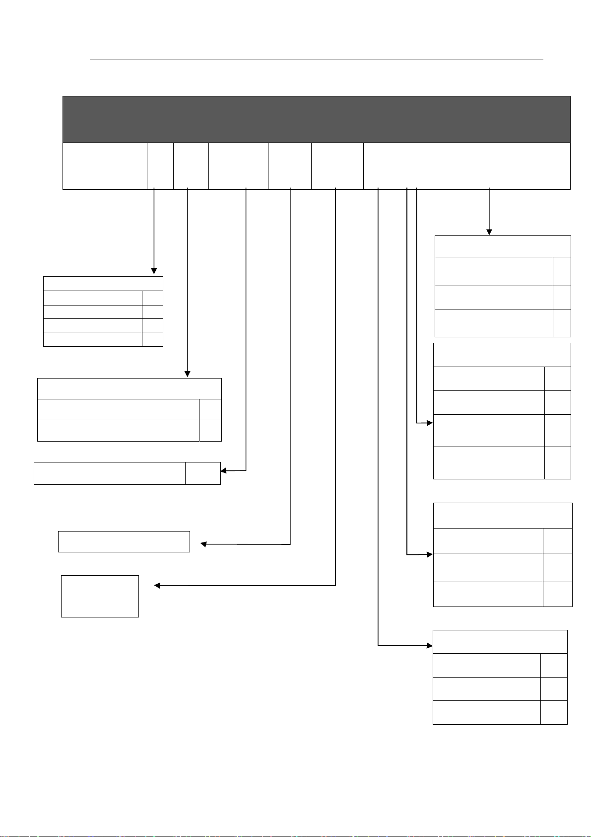
1. Identification data
RECEIVER UNIT ID
M880
TYPE
MODULAR UNIT H
INTEGRATED UNIT L
DIN RAIL UNIT M
UNIT ---------- ---
POWER SUPPLY
ALTERNATING CURRENT
DIRECT CURRENT
A BB XXXXX VV
CCC
X Y W Z
RECEIVER Output TYPE
UNMANUFACTURED CASE or
DIN RAIL
CABLE GLANDS
RECESSED MULTIPOLAR PLUG
C
AC
DC
OUTPUT
RECEIVER WIRING
NOT CABLED
INTERNAL WIRING
CABLE + plug output
N
P
I
N
I
S
PROJECT REFERENCE NUMBER
RX VARIANT NUMBER
WIRING/CABLING
VARIANT
NNNNN
External wiring with
DIN43650
P
Receiving Antenna
INTERNAL I
EXTERNAL ON THE BOX
(WHIP)
EXTERNAL WITH CABLE O
S
Operating Frequency
Wired F
433 MHz (Europa) E
2,4 GHz (World Wide) W
M880 ALL EN 2.7.2.docx 5/56
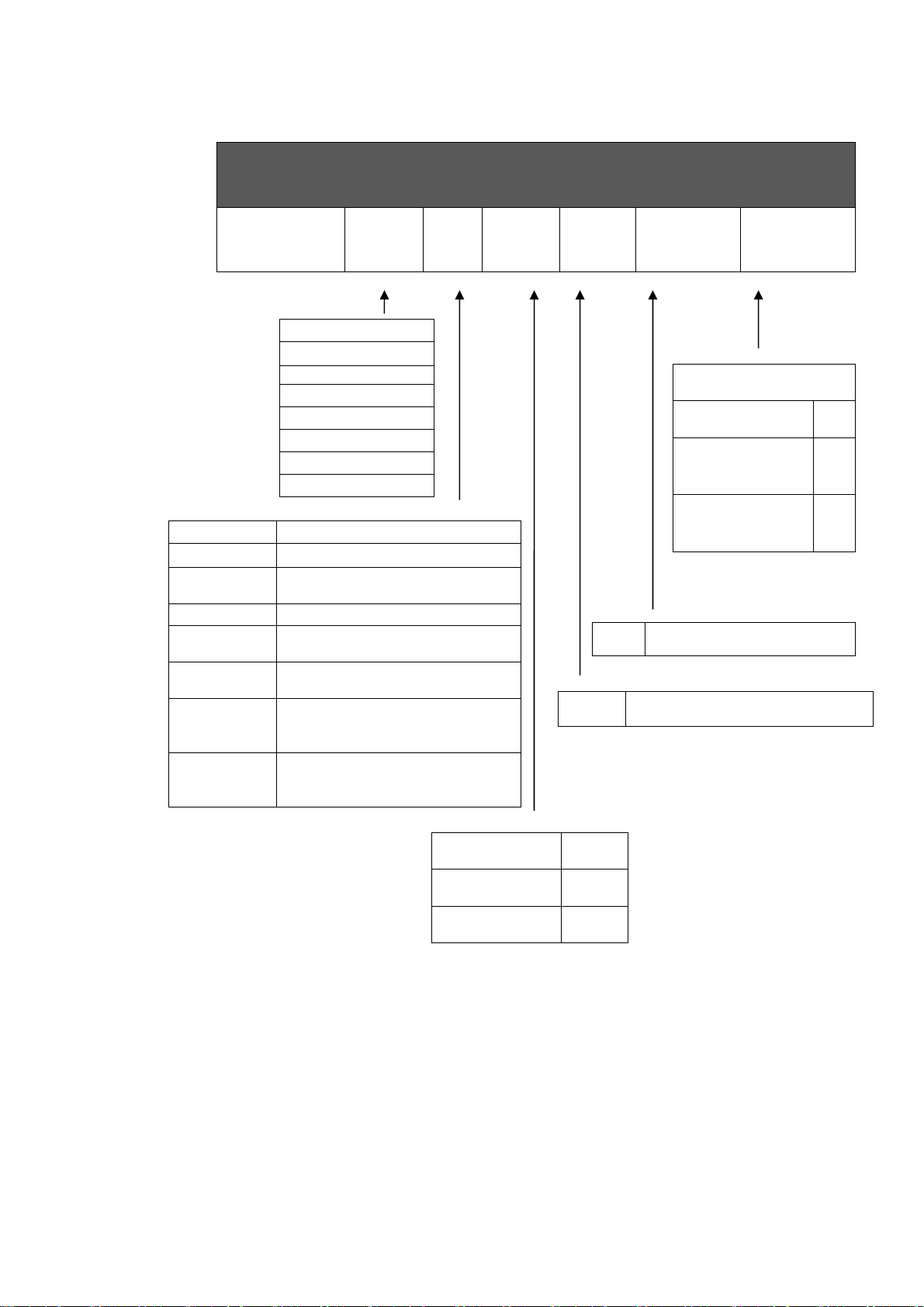
M# Up to 9 single axis joysticks
B# Up to 4 dual axis joysticks
X# Up to 7 single and dual axis
NJ No joysticks
L##
(WAVE2 only)
S#
(WAVE2 only)
E##
(ARES2 only)
C##
(ARES2 only)
M880
THOR2
ZEUS2
KRON
ARES2
WAVE2
G4L
G4S
MODIN
joysticks
Pushbutton transmitter with 10 or
12 buttons + Start/Stop
Pushbutton transmitter with 6 or
8 buttons + Start/Stop
Transmitter with selectors,
buttons and potentiometers
(from 2 to 10) with STOP button
Transmitter with selectors,
buttons and potentiometers
(from 2 to 10) NO_STOP button
Type
TRANSMITTER UNIT ID
Sub
Type
Display
Project
#
nn TX Variant number
nnnnn Project reference number
Variant
TX
Operating
Frequency
Operating frequency
Wired F
433 MHz
(Europa)
2,4 GHz (World
Wide)
E
W
Yes D
Not mounted N
None
6/56 M880 ALL EN 2.7.2.docx
1.1. Documentation
All IMET radio remote controls are accompanied by the following documents:
User’s Manual (the annexes are an integral part of the manual)
Warranty Certificate
If any document is missing, please contact IMET and provide the unit’s serial number.
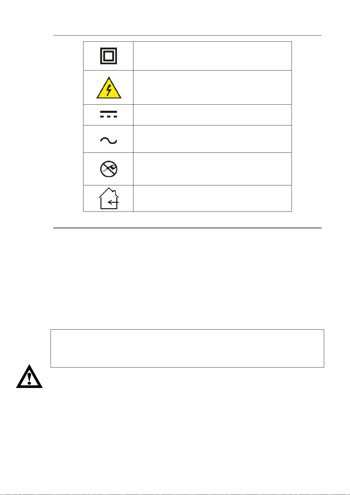
2. CONVENTIONS USED IN THIS MANUAL
Warning: This symbol indicates instructions to be strictly followed for the radio remote control to
work properly.
Danger: This symbol indicates important information aiming to prevent dangerous situations when
using the radio remote control.
Note: This symbol indicates useful suggestions for the proper use of the radio remote control.
3. CAUTION
READ THE INSTRUCTIONS CAREFULLY BEFORE INSTALLING THE RADIO REMOTE
CONTROL! FAILURE TO APPLY ANY OF THE PROCEDURES DESCRIBED IN THIS MANUAL
MAY LEAD TO INJURIES TO PERSONS OR DAMAGES TO PROPERTY.
NO PART OF THE RADIO REMOTE CONTROL SHOULD BE USED AS A SPARE PART FOR
OTHER RADIO REMOTE CONTROLS.
Follow the local laws on safety and workplace accident prevention. All the regulations on using radio
remote controls for industrial machinery MUST BE OBSERVED AT ALL TIMES.
IMET assumes no responsibility for the unlawful use of the radio remote control.
3.1. Risk analysis
It is necessary to evaluate the risks in order to establish the safety and health safeguard requisites
concerning the machine using the radio remote control. A risk analysis must be carried out when
deciding whether an application can be radio controlled or not. It should be carried out by qualified
personnel (the installer), who assumes all the relevant responsibilities.
IMET assumes no responsibility for failure to carry out a proper risk analysis.
An eventual loss of communication between the transmitter and the receiver, caused by disturbances
or electromagnetic interferences, shall automatically block the radio command (clause 9.2.7.3 EN
60204-32), thus implying a restart of the machine. This casual shutdown should be foreseen in the risk
analysis.
3.2. Applications
The most common radio remote control applications regard lifting or carrying equipment, such as
tower cranes, bridge cranes, truck cranes and concrete pumps. Other applications are possible
provided the following conditions are observed:
Do not use the radio remote control in environmental or electrical conditions other than those specified
in Chapter 12. Do not use the radio remote control in environments that are required to be explosionproof.
M880 ALL EN 2.7.2.docx 7/56
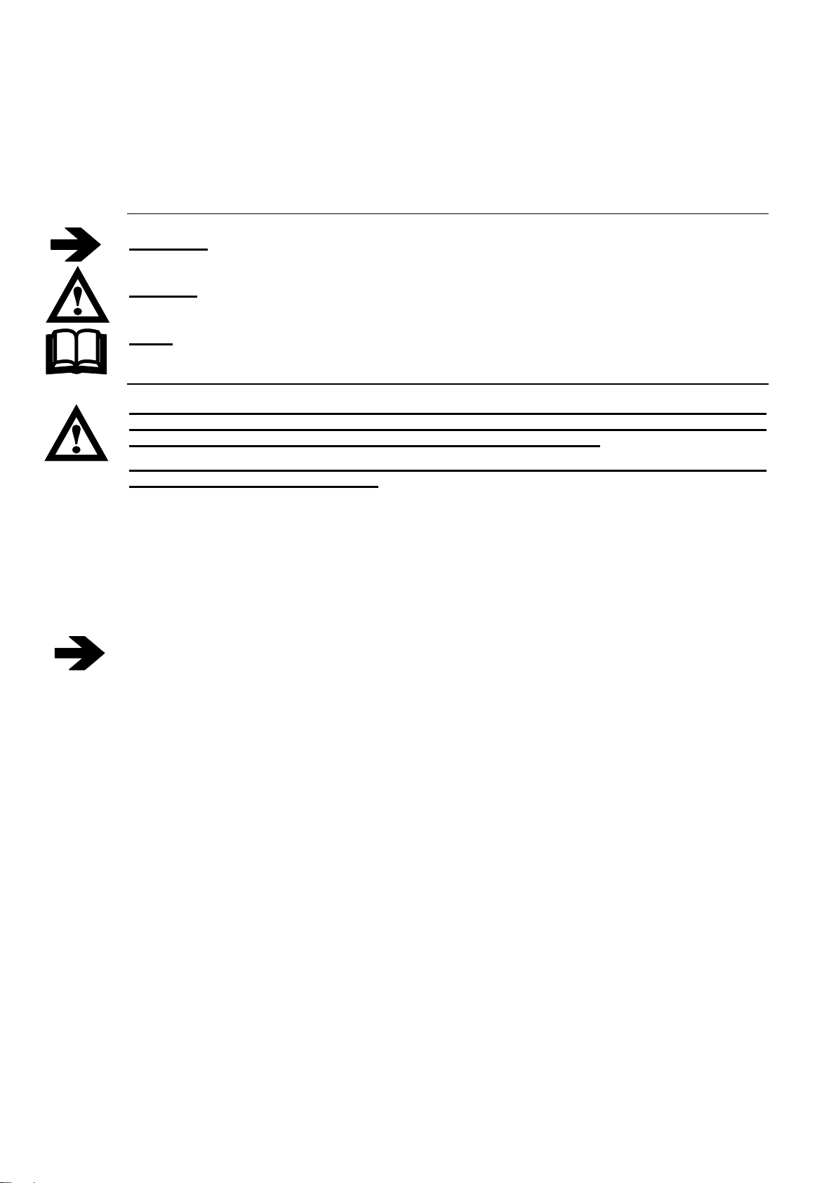
4. SIGNIFICANCE OF THE SYMBOLS IN LABELS
Class II equipment
To identify equipment meeting the safety requirements
specified for Class II equipment according to IEC 60536
Dangerous voltage
To indicate hazards arising from dangerous voltages.
Direct current
To indicate on the rating plate that the equipment is
suitable for direct current; to identify relevant terminals
Alternating current
To indicate on the rating plate that the equipment is
suitable for alternating current; to identify relevant
terminals
Don’t use high-pressure water
To indicate not to clean using high-pressure water jets
In house use
To indicate Indoor use only
5. FCC-Regulatory Information (2,4 GHz radio module)
This equipment has been tested and found to comply with the limits for a digital device, pursuant to
Part 15 of the FCC Rules. These limits are designed to provide reasonable protection against harmful
interference in a residential installation. This equipment generates, uses and can radiate radio
frequency energy and, if not installed and used in accordance with the instructions, may cause harmful
interference to radio communications. However, there is no guarantee that interference will not occur
in a particular installation. If this equipment does cause harmful interference to radio or television
reception, which can be determined by turning the equipment off and on, the user is encouraged to try
to correct the interference by one or more of the following measures:
•Reorient or relocate the receiving antenna.
•Increase the separation between the equipment and receiver.
•Connect the equipment into an outlet on a circuit different from that to which the receiver is
connected.
•Consult the dealer or an experienced radio/TV technician for help.
This device complies with Part 15 of the FCC Rules and with RSS-210 of Industry Canada.
Operation is subject to the following two conditions:
1) this device may not cause harmful interference, and
2) this device must accept any interference received, including interference that may
cause undesired operation
WARNING:
Changes or modifications made to this equipment not expressly approved by IMET may void
the FCC authorization to operate this equipment.
RF EXPOSURE NOTICE:
The radiated output power of this device is below the FCC radio frequency exposure limits.
Nevertheless, the transmitters shall be used in such a manner that the potential for human contact
during normal operation is minimized.
Operating the transmitter with its carrying belt guarantees the compliance with RF exposure
boundaries.
In order to avoid the possibility of exceeding the FCC radio frequency exposure limits, human
proximity to the receiver’s antenna shall not be less than 20cm (8 inches) during normal operation
8/56 M880 ALL EN 2.7.2.docx
6. PREVENTIVE MAINTENANCE
Before performing any maintenance operation, turn off the power to both, the receiving unit
and the machine, and remove the battery from the transmitter.
Do not expose to heat sources
Avoid prolonged exposure to direct sunlight
Do not wash the device with water under pressure or dip it in water
Avoid contact with oil or solvents
If the device has been opened for any reason, make sure all the seals and gaskets are in place
when closing
When cleaning it, do not use alcohol or solvents, as they might damage the components and the
housing.
6.1. Routine maintenance to be carried out by the operator
Periodically clean the outside of the receiving and transmitting units. Dirt deposits could hinder the
functioning of buttons, toggle switches and manipulators.
Apply special care to the STOP button, by keeping it clean and making sure it works effortless.
Remove any traces of rust from the battery contacts.
Check the casing and the components for cracks or apparent damages.
All rubber parts, buttons, seals and gaskets should show no sign of tearing.
Damaged components should be immediately replaced to prevent humidity or dirt from penetrating
and jeopardizing the safe operation of the radio remote control.
6.2. Maintenance and internal checks
After every year of use, we recommend carrying out a general inspection of the radio remote control
(to be performed by qualified personnel).
Open the housings of the transmitting and receiving units and make sure:
that the gaskets are in good shape
that the cable clamps are efficient
that the connection terminal screws and the connector couplings are tight
that the electronic boards are securely fastened
that the fastening screws of all components are tight
Although IP65 units are hermetically sealed, dust and humidity may accumulate over time when
working in particular conditions. Carefully remove any foreign matter.
When closing the transmitting unit, apply special care to the casing’s sealing, in order to prevent the
infiltration of humidity.
Power on the device, being careful not to touch any live parts in the receiving unit, and perform the
following tests:
Check the functioning of all the controls.
Verify that the STOP circuit intervenes correctly. By pressing the STOP button during operation,
the relay contacts A and B of the E-STOP circuit must open.
Any broken parts must be replaced with original spare parts, in order to keep the characteristics of
the radio remote control unchanged. See the list of parts that can be replaced in Chapter 13.
M880 ALL EN 2.7.2.docx 9/56
7. INSTALLING THE RADIO REMOTE CONTROL
We recommend following the instructions below, in order to set up a properly operating radio remote
control system.
The radio remote control should be installed by qualified personnel only.
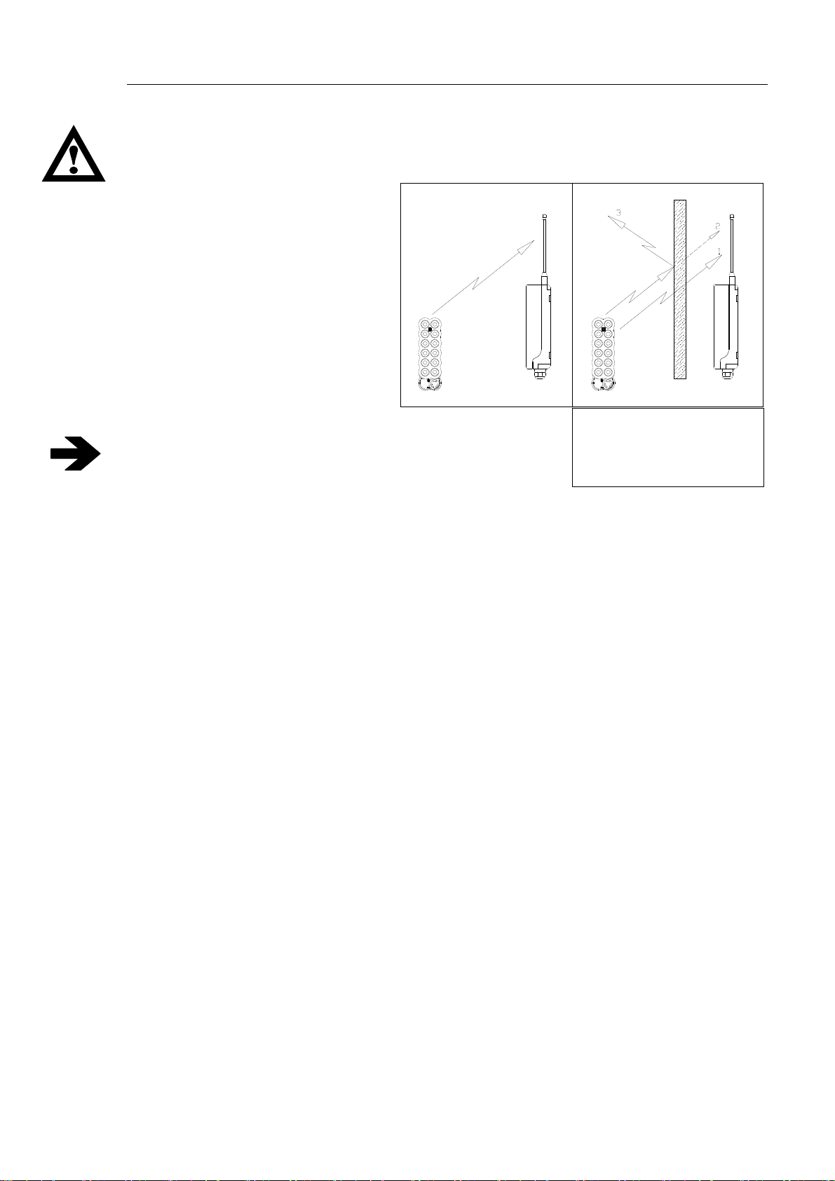
Install the receiving unit or its antenna (in case of versions with an external antenna) in the line
of sight of the transmitting unit, with
no electromagnetic shielding. To
improve the operating range when
the antenna is integrated, do not
install the unit on metal surfaces, if
possible.
Do not bypass the machine’s safety
F
R
systems; follow the manufacturer’s
instructions.
Do not install the receiving unit too high
above the ground (1020 metres). At
these heights the unit may receive local
radio signals that could disturb
S
T
P
O
O
P
E
S
T
T
E
R
S
R
E
T
S
E
E
S
T
E
R
RECOMMENDED
transceiving operations.
To prevent water infiltrations, install the receiving unit
vertically, with the cable clamps and any other connections at
the bottom, as shown in the figure.
ANTENNA ANTENNA
F
R
S
T
P
O
O
E
P
T
S
T
E
R
S
R
E
T
S
E
E
S
T
E
R
1 Non-attenuating obstacle
2 Partially attenuating
obstacle
3 Shielding obstacle
In case of strong mechanical vibrations, place a rubber shock-absorber between the machine and the
receiver (dampers).
10/56 M880 ALL EN 2.7.2.docx
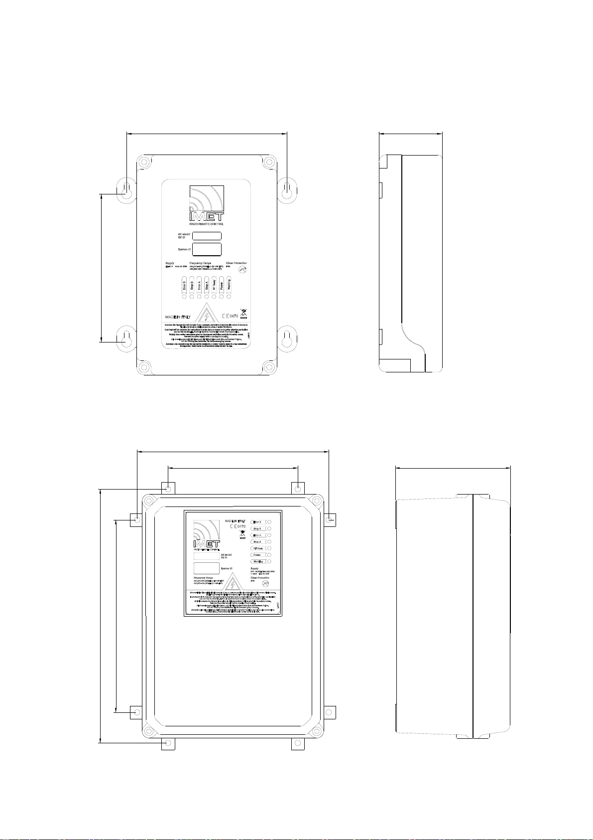
7.1. Receiving unit dimensions and drilling diagram
153
162
M880 LAC and M880 LDC versions
64
217
147
290
220
M880 HAC and M880 HDC versions
131
M880 ALL EN 2.7.2.docx 11/56

7.2. Connecting the receiver
Do not perform any operation until the equipment is powered off.
The power supply for the radio remote control should be located downstream from the machine’s main
switch.
Connecting it directly to the mains distribution network is prohibited. The mains disconnecting
switch must be equipped with a device to prevent unauthorized closing (padlock). It must be
easily accessible and be attached outside of the equipment. The distance between contacts
must be of at least 3 mm.
The connection between the receiving unit and the machine should always be REMOVABLE. If the
connection is made directly on the terminal board inside the machine, a multipolar connector should
be used, so that the receiver can be disconnected and the original wired controls restored at any time.
Conductors and cables shall be selected so as to be suitable for the existing operating conditions (for
example, voltage, current, protection against electric shock, grouping of cables), as well as external
influences (for example, ambient temperature, presence of water or corrosive substances, mechanical
stresses-including stresses during installation- and fire hazards). When cables are installed on hoisting
machines used in the open air (outside buildings or other protective structures), they shall be suitable
for outdoor use (for example, UV-resistant, adequate temperature range), or be appropriately
protected.
The wire connections between the receiving unit and the machine should respect the Standard
EN60204 and must be stranded. The wires must have a cross-section of at least 0.75 mm2 and less
than 13 mm2 and be self-extinguishing. If the equipment is used with ambient temperature of 70°C the
maximum conductor operating temperature must be greater than 75°C.
Use ferrules for conductor ends, if possible, and make sure that the terminals are fastened tightly.
Consult the transmitting unit control diagram (Annex T) and the receiving unit wiring diagram (Annex
R) to identify the equivalent actuators in both units.
In the HDC version, the receiver is also intended to be electrically powered at a voltage of 24 VAC
50/60 Hz. Connect it to an external source where the dedicated 24 VAC output is separated from
dangerous voltage parts by double or reinforced insulation.
In all receiver versions, the loads connected to the relay board must have a protection against over
currents and overloads.
In the HDC version, the receiver is intended to be electrically powered in the voltage range 11 to 30
Vdc. Connect it to an external source where the dedicated 11-30 Vdc output is protected against
overvoltage and short circuit. The 11-30 Vdc dedicated output external source must be connected to
the main terminal earth protection or separated from the primary circuit by means of a metal screen
connected to the main terminal of the earth protection.
When the receiver type HDC is provided with a metallic connector (mounted on the enclosure), the
device shall be placed in a "service access area" not accessible to the operator, but only by the
service staff (EN 60950-1 4.5.4 Touch temperature limits of metals at 70°C)
Be sure to note the supply voltage when connecting the receiving unit.
In versions HAC and LAC, the fuse current must be adjusted to the supply voltage.
After installing, test the radio remote control and the machine to make sure they work as
expected. In addition, it is very important to make sure that the STOP circuit works properly.
Pressing the STOP button during normal operation should open the contacts of relays A and B
in the E-STOP circuit.
Lastly, fill-out the sheet showing the connection diagram between the receiving unit and the machine
and write down the date of installation in the document DECLARATION OF CONFORMITY.
12/56 M880 ALL EN 2.7.2.docx
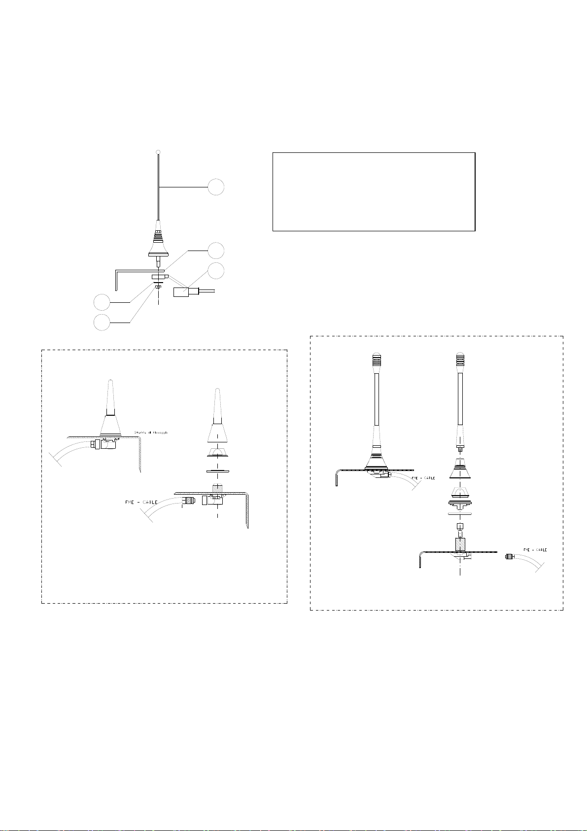
7.3. Installing the external antenna
A properly installed antenna is essential for a good operating range. Install the antenna outside at the
highest and most visible point and far from metal structures. Use a tuned antenna only, and connect it to
the receiver using an RG58 coaxial cable (impedance 50). Only use the antennas supplied by IMET;
other types of antenna must be approved in conformity to the standard ETSI EN 300 200-2.
1
SYMBOLS
1 Antenna whip
2 Fastening bracket
3 RG58 cable with protective sheath
4 Washer
5 Locking nut
2
3
4
5
P3540/SC
MU 7 - LX/h
M880 ALL EN 2.7.2.docx 13/56

7.4. STOP (E-STOP)
Connect the contact of the E-STOP circuit so that it commands the coil of the machine’s main line
contactor and remember that the maximum allowable current is 5A with resistive load.
Attention: In order to maintain the safety category (PLe Category 4 according to ISO 13849-1),
the STOP circuit relays must be connected in series (standard IMET pre - wiring configuration),
or else in AC applications, individually connected in series to the phase line and neutral, ONLY
for the mains power interruption (See Example 2). In series to the STOP relay contacts, there
must always be a 5A fuse.
7.5. SAFETY ENABLE (S-ENABLE)
The Safety Enable is an additional safety function. It consists of a relay in the receiver that is
monitored by the RX logic and that can be associated with the commands sent by the transmitter,
which in case of problems, automatically stops the receiver, as shown by the LEDs status.
Example 1 (in series with control commands): The Safety Enable introduces a redundancy, which
activates the safety function in case the control command relays fail to open.
Example 3 (operating the bypass valve): The Safety Enable can command the drain valve in a
hydraulic machine, such that the machine is powered only when a control command is given.
The Safety Enable must not be associated with stable selection commands
The risk analysis and safety class are based on standard ISO 13849-1. Take good notice of the
maximum currents allowed on the relay contacts (see Chap. 12).
Example 1: Wiring of the S-ENABLE relay for AC applications
Example 2: Alternative for special applications (for LAC receivers only)
14/56 M880 ALL EN 2.7.2.docx

Example 2: Alternative for special application
Example 3: Wiring of the Safety Enable relay for DC applications
M880 ALL EN 2.7.2.docx 15/56
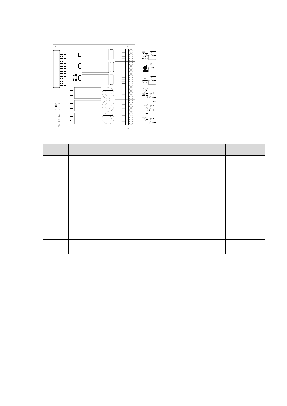
7.6. Basic functions board PCB201 (DC) / PCB231 (AC) (Service card)
The table below shows the basic functions available on the service board.
Relay Function
Typical Uses Remarks
TIMEDRELAY
SAFETY-
ENABLE
E-STOP The two relays are activated when the radio remote
HORN Horn control relay Warns of potentially hazardous
START START control relay Powers the machine’s control box
The relay is activated for 5 seconds from the moment
the radio remote control is switched off or has entered
in passive emergency mode.
The T-RELAY can be activated at switch-off or with a
2-second delay.
The relay is activated only by an unstable command
from a toggle switch, button or joystick
When Connected in series, the function introduces a
redundancy that can be used to increase function
safety
control is switched onwith the START button (STOP
RELAY with PLe cat. 4 ISO13849-1) and stay active
until a STOP command intervenes (pressing the
STOP button or passive emergency)
Delayed STOP of
combustion engine
Engine deceleration
Enables the drain valve
Common enabling of control
commands
Powers the main contactor
in the machine’s control box
Common power supply for
control commands
Machine power supply
situations
and enables the machine Start
function
Relays constantly
monitored by uP.
Relays constantly
monitored by uP
it can be associated
to the first START
The SAFETY-ENABLE on the 9-relay board can be activated only by the ones present on the board
itself.
7.7. Connection diagrams of H receivers
The receiving unit version H is provided with 7 slots, where control relay cards, analog output cards
and a data feedback card can be inserted. The basic functions/controls in the table above are located
in the SERVICE board.
The basic receiver configuration includes the power supply board with the relay card on SLOT B, the
logic card on SLOT RX and the SERVICE card on the SERVICE slot.
According to the project specifications, you may have:
RELAY cards (8 + SAFETY, 10 and 13)
MOSFET cards (8 + SAFETY, 10 or 12)
Analog output card
Data feedback card (PCB262) to be inserted in slot A
The configuration HAC does not allow for the use of 13-relay cards, due to the presence of the AC
transformer.
16/56 M880 ALL EN 2.7.2.docx
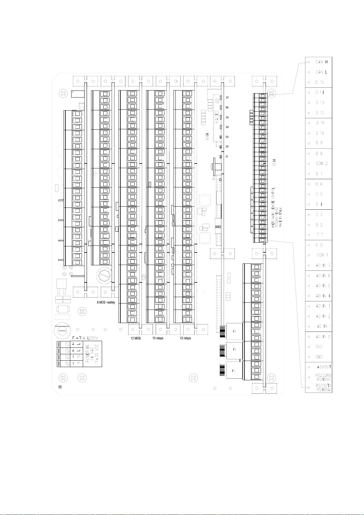
7.8. HDC (PCB200) receiver with analog output cards and data feedback card
+Vin
12
VOut
+Vin
VOut
+Vin
3
ACH5 ACH6 ACH7 ACH8ACH1 ACH2 ACH3 ACH4
VOut
+Vin
4
VOut
+Vin
56
VOut
+Vin
VOut
+Vin
7
VOut
+Vin
8
VOut
C
C
SAFETY
ENABLE
NO
12
3
4
56
7
89
10
11
12
+Vin
VOut
+Vin
VOut
+Vin
VOut
+Vin
VOut
+Vin
VOut
+Vin
VOut
+Vin
VOut
+Vin
VOut
+Vin
VOut
+Vin
VOut
+Vin
VOut
+Vin
VOut
C
NC
NO
C
21
NC
NO
C
3
NC
NO
C
4
NC
NO
C
NC
NO
C
65
NC
NO
C
7
NC
NO
C
NC
NO
C
98
NC
NO
C
NC
10
NO
C
11
NO
C
12
NO
C
13
NO
C
NC
NO
C
NC
NO
C
NC
NO
C
NC
NO
C
NC
NO
C
654321
NC
NO
C
NC
NO
C
NC
NO
C
987
NC
NO
C
NC
10
NO
C
11
NO
C
12
NO
C
13
NO
Error-B
Stop-B
Error-A
Stop-A
RF Busy
POWER
Working
NC
NO
NC
NO
NC
NO
NC
NO
NC
NO
NC
NO
C
C
C
C
C
TIMED
RELAY
HORN
START
SAFETY
ENABLE
E-STOP A
C
M880 ALL EN 2.7.2.docx 17/56
 Loading...