

IMET BS 400 SHI Original Instructions Manual
TRADUCTION OF THE ORIGINAL INSTRUCTIONS FOR USE
BS400 SHIeng ED.2010 rev.00
1/45
IMET Spa
Loc. Tre Fontane
-Cisano Bergamasco
Tel. 035/4387911
Fax. 035/787066
Web site: www.imetsaws.com
E-mail: imet@imetsaws.com
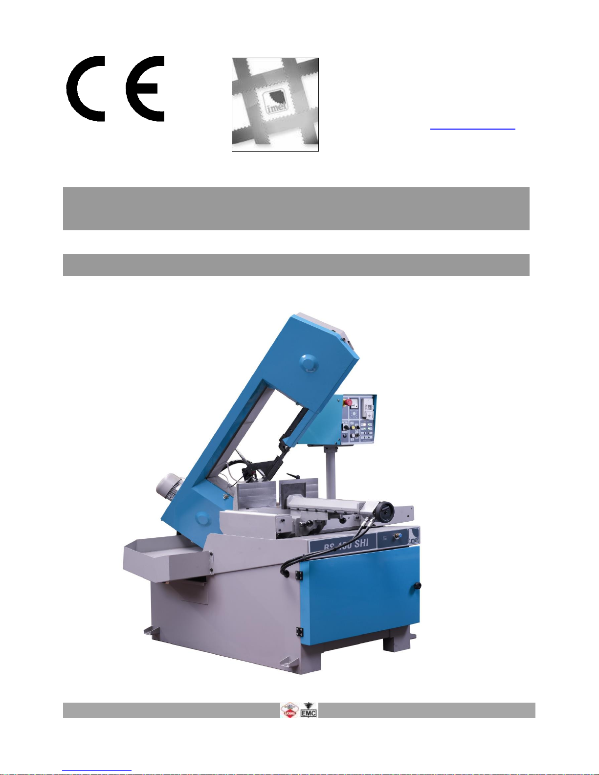
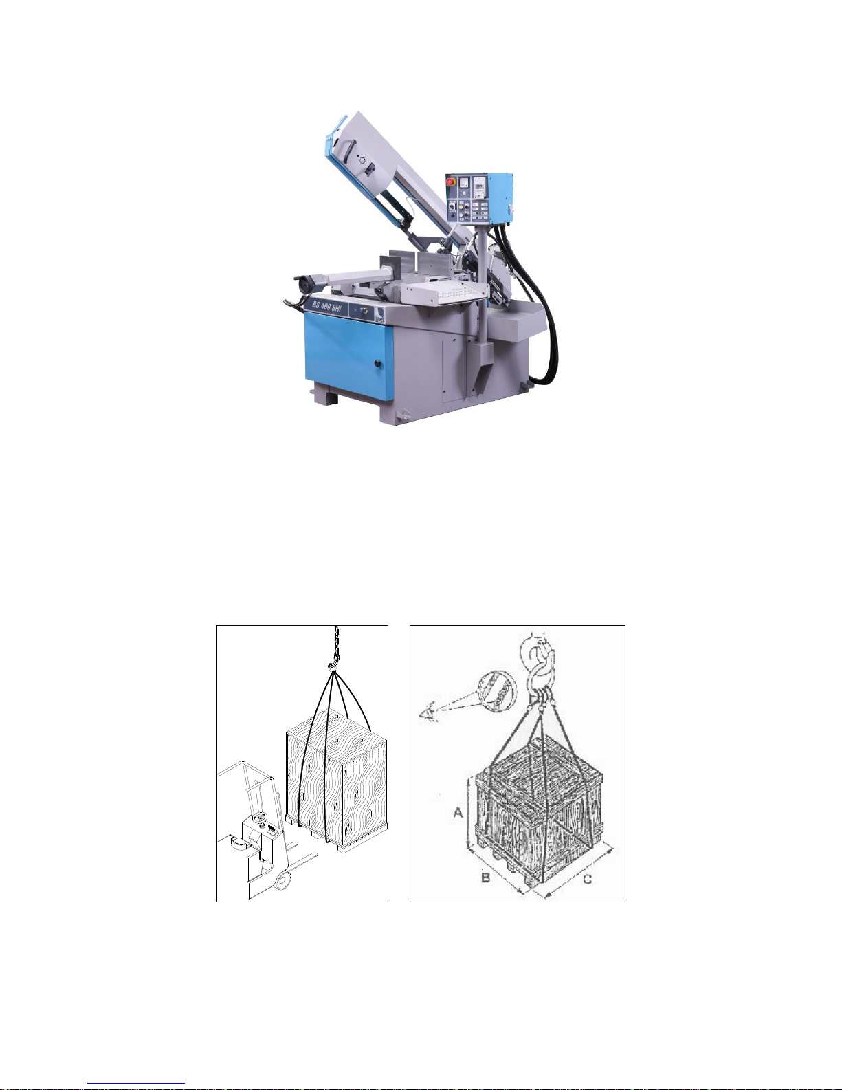
Bandsaw BS 400 SHI
Semiautomatic - Hydraulic
INSTRUCTIONS FOR USE
INSTRUCTIONS FOR USE
BS400 SHIeng ED.2010 rev.00
2/45
We recommend to read carefully the information here included in order to install, use and maintain correctly and safely
this machine.
Please refer always to this instruction manual in case of assistance service (in Italy: +39 035 4387918 or +39 035
4387828) need and keep it carefully for all the machine life. The reference number is shown on the cover.
A consequence of the continuous improvement of the product is that some images/descriptions here included could not
correspond to the improved features of the machines.
Your kind collaboration would help us in intevening asap.
In the enclosed Compliance Declaration you will find the Safety and Reference Norms applied during the planning and
construction of this machine.
The choice and the use of the parts have been made by considering the conditions of use and the long machine life.
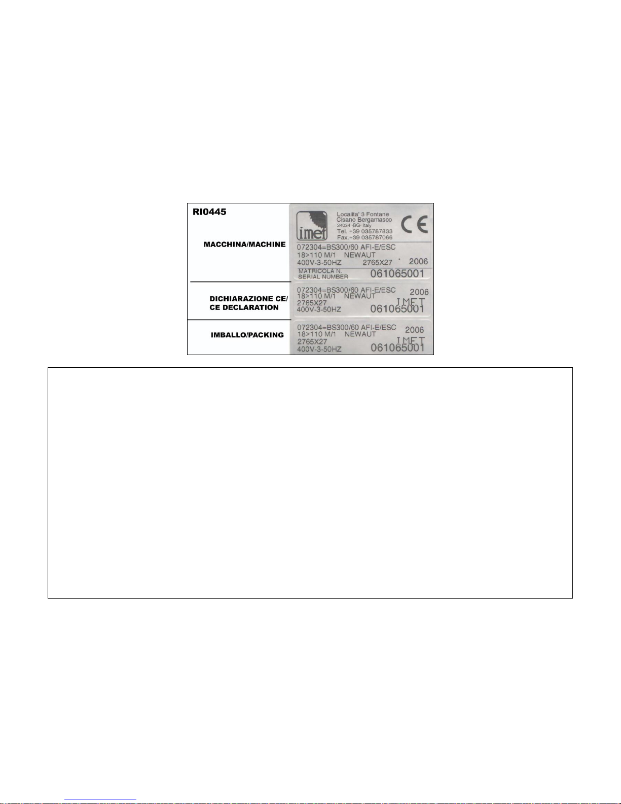
The identification plate, with the serial number, is fixed on the front right angle of the base or on a side of control box.
1.1 - ATTACHED DOCUMENT FOR E.M.C. ( INDUSTRIAL ENVIRONMENT)
The user is responsible for the installation and use of this machine in compliance with the manufacturer's instructions
shown in this manual. This equipment meets the protection requirements in accordance with the Directives 2006/42/EEC,
2004/108/CE for Electromagnetic Compatibility (EMC). In particular, it follows the technical guidelines of the Directives
EN55011, EN50082-2 and it has been made for industrial and not for household use.
In the event of electromagnetic interferences the user is responsible for solving the problem with the help of the technical
assistance by the manufacturer. Before installing the machine the user must take into account possible electromagnetic
problems of the working area. In particular, we suggest to install the machine away from:
-signalling, control and telephone cables;
-radio-television transmitters and receivers;
-computers or controlling and measuring instrument;
-safety and protection devices.
The electric supply cable must be kept as short as possible, without any twists.
Covers, doors and the frame must be suitably closed when the saw is operating.
Under no circumstances the machine must be modified except for adjustments and changes specifically approved by the
manufacturer. Follow the maintenance schedule.
INSTRUCTIONS FOR USE
BS400 SHIeng ED.2010 rev.00
3/45
===========================================================================
CE DECLARATION OF CONFORMITY (encl. II A DIR 2006/42/CE) / 01
===========================================================================
THE MANUFACTURER : IMET S.p.A
Località Tre Fontane
24034 - CISANO BERGAMASCO –BG- ITALIA
HEREBY DECLARES THAT
in designing and manufacturing the machine described here below , we have considered the most important requirements
of safety and health dictated by the European Directives of the Machine Security. Remember that this declaration loses its
validity if machine is modified without our agreement.
Trade name BAND SAWING MACHINE FOR METALS
Code / Model / Type
Manufacturing year
Serial number
IT IS IN COMPLIANCE WITH THE DIRECTIVES
DIRECTIVE 2006/42/CE OF THE EUROPEAN PARLIAMENT AND OF THE COUNCIL OF THE
17TH/05/2006 REGARDING THE MACHINES AND THAT MODIFIES THE DIRECTIVE 95/16/CE;
DIRECTIVE 2004/108/CE OF THE EUROPEAN PARLIAMENT AND OF THE COUNCIL OF THE
15/12/04 REGARDING THE ELECTROMAGNETIC COMPATIBILITY -EMC-
DIRECTIVE 2006/95/CE OF THE EUROPEAN PARLIAMENT AND OF THE COUNCIL OF THE
12/12/06 REGARDING ELECTRICAL EQUIPMENT FOR USE OF LOW VOLTAGE -LVD-
HARMONIZED STANDARDS REFERENCE EN.12100-01; EN 55011, EN50082-2, EN 13898, EN 60204
LEGISLATIVE DECREE N.17 OF THE 27TH OF JANUARY 2010.
AND AUTHORIZING THE PERSON LISTED BELOW TO ISSUE THE TECHNICAL FILE.
Date : 01.01.2010
The signatory identification The manager
Angelo Meroni
-------------------------------------------------------------------------------------------------------------------------File : Machine no. Delivery note no Dated
--------------------------------------------------------------------------------------------------------------------------…………………….
ORIGINAL WITHIN THE MACHINE...
………………..

INSTRUCTIONS FOR USE
BS400 SHIeng ED.2010 rev.00
4/45
3 - MACHINE NOISE
The noise level of the working area - given the conditions described below - is determined by the simultaneous working of
several parts of the machine in motion (according to the working cycle), in addition to the tool when cutting the material.
The noise level is detected in different moments, corresponding to different working phases. The proper device is placed
about 1 meter near the machine and about 1,60 m above the floor. The results of each test is in dBA and they are
the average of 3 tests made from the left side, opposite side and right side.
For any machines the working conditions are the following:
When idle, at the maximum blade speed: dBA 63
During the cut, at a suited blade speed, cutting solid steel (St12=≈C20, 80mm diameter): dBA 75
(tolerance ± 2dB).
In the standard production the test is made on a machine like this, in compliance with E.C. safety norms 2006/42/CE and
EN13898. Using the saw in bad conditions or using wrong tools causes significant alterations of these tests and it
jeopardizes the health of the staff and the good results of the work. Useful is the European Guideline 2003/10/CE.
The noise depends mostly on the cutting material, on its size and on the clamping. Considering that the above mentioned
decibels could be exceeded, we recommend the operator to use personal protections (headsets, plugs, and so on) when
working for a long time with high noise levels.
3.1 - ADDITIONAL HEALTH AND SAFETY REQUIREMENTS
The machines manually controlled by an operator during all work phases must comply to further health and safety
requirements as specified by article 2.2 of the Annexed I of the European Directive 2006/42/CE and following integrations.
In particular, the level of the machine vibrations when working must be clearly specified in the instructions.
This machine does not produce vibrations higher than 2.5 m/s2
The measurement procedure is in compliance with the general norms applied to this type of machinery.
As in the previous paragraph, using the machine in unsuitable conditions or using the wrong tools can cause
changes affecting this value, causing a risk to the health of the working staff as well as the quality of the
production. Useful is the European Guideline 2002/44/CE.
Vibrations produced during the cut may be amplified by the material, by its dimensions and its
positioning/clamping in the vice.

INSTRUCTIONS FOR USE
BS400 SHIeng ED.2010 rev.00
5/45
4 - GUARANTEE NORMS
I.ME.T. offers a wide range of sawing machines and accessories, destined to who buys/uses them as part of a
commercial or professional activity.
The manufacturer grants that this product has been strongly controlled and that there are no defects in the used and
working materials for a period of 12 months from the date of the delivery note.
The italian law D.L. n° 24 issued on 02/02/2002 and valid since 23/03/2002 (which carries out the European Directive
1999/44/CE) indicates different terms only for convenience products for private use.
If the user points out some defects to the manufacturer during the warranty time, the manufacturer will replace the
components that are considered defected.
In case of reparation of the machine during the warranty time the shipment will be accepted only if the delivery is Free
Destiny (that is the freight costs are supported by the owner of the machine), and the return of the machine to the
customer is considered EX WORKS.
If the manufaturer is not able to remplace a component within an acceptable time, both companies (manufacturer and
user) will reach an agreement for satisfying completely the needs of the user.
The a.m. warranty is not valid in case of accidental damages, or defects provoked by a wrong use of the machine or
maintenance, by variations made on the machine, or by the use of the machine in a place not corresponding to the
indicated enviromental specifications.
4.1 - The manufacturer does not offer further warranties, written or spoken, explicit or implicit of its products and does not
offer implicit warranties on saleability or adequacy for particular uses not foreseen by the agreement.
The a.m. limitations and exclusions can also be not applicable in Countries, where there are no implicit limits of warranty
time on the products. Anyway each implicit warranty is limited to a time of 12 months from the date of the delivery note.
4.2 - The date of manufacture, deducible from the serial number placed on the machine, is a very necessary reference for
the warranty, for the assistance after-sale and for the identification of the product.
Each tampering on the products, expecially the installation of safety devices, will relieve the manufacturer of any kind of
responsability.
The parts most subject to rapid and continuous wear are not included in the warranty (for example: transmission belts,
gaskets, oils, blades, and so on).
For the electrical, electronic and hydraulic equipments and for the other equipments having its own individuality (of which
there is the possibility to know the name of the constructor), the manufacturer gives to the user the same warranty
received by the primary constructor of these parts.
4.3 - The components replaced during the assistance operated by the manufacturer have a warranty of 6 months from
the installation date indicated on the Technical Service paper, one copy of which is given to the owner.

INSTRUCTIONS FOR USE
BS400 SHIeng ED.2010 rev.00
6/45
5 - SUMMARY pag.
1- PREMESSA 2
2 – CONFORMITY DECLARATION 3
3 – AIR NOISE 4
4 – GUARANTEE NORMS 5
5 – Index 6
6 – Technical characteristics 7
7 – Installation – minimum requirements 9
8 – Moving and transit 9
9 – Fittings/optionals 11
10 – Blade choice 12
11 – Foreseen use and controindications 14
12 – Machine description 17
13 – Work preparation 18
14 – Band tensioning 19
15 – Functioning 20
16 – Regulations 25
17 – Maintenance – for the user 27
18 – Band running-in 28
19 – Machine running-in 28
20 – Draining of used/produced substances 29
21 – Trouble-shooting 29
22 – Machine demolition 31
23 – Spare parts 32
24 – Maintenance – for qualified technicians 33
Electrical drawings
Hydraulic diagram
Spare Parts drawings
INSTRUCTIONS FOR USE
BS400 SHIeng ED.2010 rev.00
7/45
6 – TECHNICAL CHARACTERISTICS
- Hydraulic semiautomatic bandsaw, mitre cutting from 0° to 60° left and from 0° to 45° right
- Hydraulic vice with adjustable guides, free to move alongside the worktable, with quick motion and clamping
- Easy stops at 0°, 45°, 60° left and 45° right
- Adjustment of the blade tension from the front side of the sawframe, checked by an end-stroke
- Blade tension 2000 kg/cm², blade guides with hard metal pads
- Steel sawframe with tubular section, pulleys 360mm diameter
- Mechanical device (position sensor) that allows the sawframe to lower quickly toward the material and detect automatically the startcut point
- Connection element for loading table equipped with roller, 450 mm wide
- Slide on the unloading side which can be transformed in connection for unloading table
- Adjustable bar stop, blade-cleaning brush, bi-metal blade
- Main switch with minimum tension coil, emergency button, thermic and magnetic motor protection, motor absorption device
- Floor stand with room inside and door, removable chip collector, coolant tank and electro-pump
- Tools and user’s book
- In compliance with CEE Safety and Electro-magnetic Compatibility Norms (EMC)
- Electrics according to the Norms EN60204-1, EN55011, EN50082-2
The technical specifications indicated in the following tables give a general evaluation of the machine and of its
performances.
If not differently indicated all data reported in this manual refer to the standard version, suitable for working
at 400 V / 50 Hz THREEPHASE.
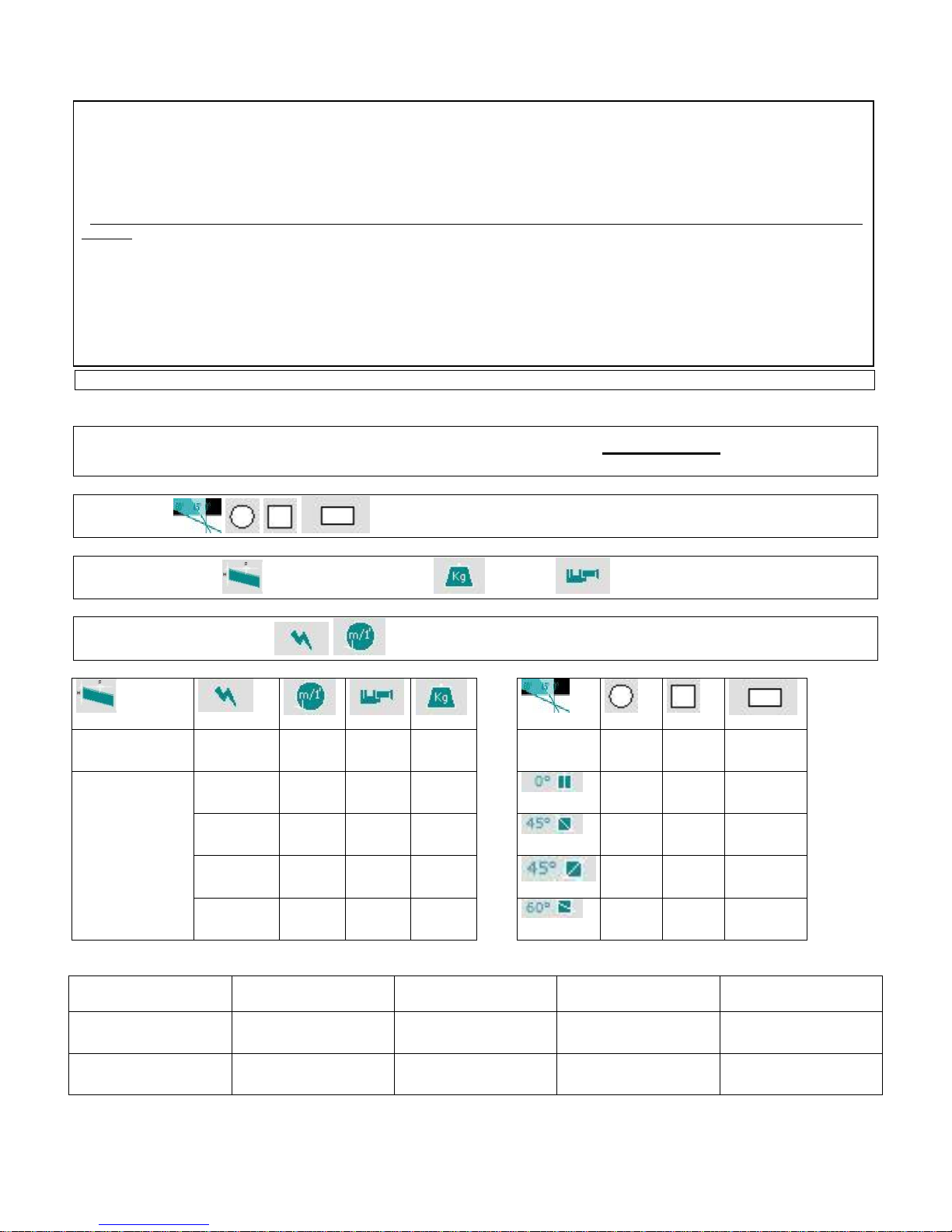
= cutting capacity ( max. dimensions on PROFILES & TUBES)
= BLADE DIMENSIONS = WEIGHT =VICE OPENING
= motor choice and blade speeds (at 50 Hz);
mm.
Kw
Mt/min
mm.
Kg.
mm.
mm.
mm.
4030x34x1,1
1.5-2,2
3~
37-74
400
680
310
280
400x250
280
270
300x200
280
270
300x200
2,2
3~
18/100
(ESC)
400
685
210
200
200x200
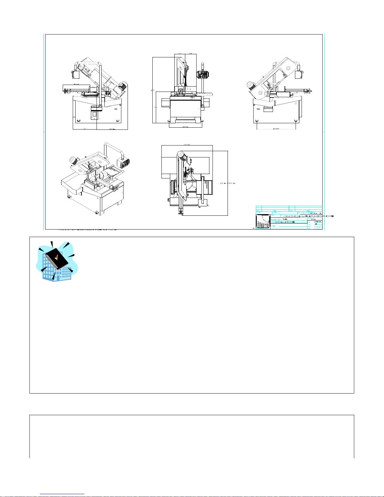
Dimensions
(mm)
B
Width
L
Lenght
H
Heigth
H min.
Worktable
In use
1480
1700
1900
940
for transport
1470
1700
1700
INSTRUCTIONS FOR USE
BS400 SHIeng ED.2010 rev.00
8/45
7 – INSTALLATION
This machine can work according to the parameters provided by the manufacturer if correctly installed and if the minimum
requirements are observed, as follows:
- It must be used indoor and with temperatures from +5 to + 40 ° C.
- The relative humidity of the environment must not be over 95%.
- The nominal value of the voltage must be between ± 10% and the frequency must be between ± 2% of the nominal
value.
The floor must have a proper loading capacity and be flat.
Floor space, operator position and working area are indicated in the included drawing that concerns only the bandsaw,
without optional accessories.
The worktable must be levelled by using the screws and nuts (NOT SUPPLIED) put in the little feet holes, dia 14 mm. The
machine has to be fixed to the floor . To grant the return of the coolant that goes onto the bars to be cut, we suggest you:
level the work-table with about 5 mm height each meters lenght to the unload side ( right side).
The included electrical schemes reproduce the necessary details to arrange the connections, to be suited for a 4
KW power request.
Earthing of all the electric parts with a dedicated GREEN/YELLOW wire, connected with a TN system to the
supply cable. A supplementary earthing point – indicated with PE – can be located on the metallic structure of the
machine.
At the origin of the power supply cables a device (such as fuses) to protect against overloading has to be
installed. On the models equipped with electronic variable-speed drive unit (ESC), in order to connect the
differential protection on the power supply line, switches with a threshold of interference on the power
dissipation of not less than 300 mA (size 0.3 A or higher is recommended) have to be employed, having possibly
time adjustment availability (0>1.5 sec).
INSTRUCTIONS FOR USE
BS400 SHIeng ED.2010 rev.00
9/45
E.M.C. - Electromagnetic noise
The user is responsible for installing and using this saw according to the manufacturer’s guidelines outlined in this manual.
This equipment complies with the protection requirements established by the Directives 2006/42/CE, 2004/108/CE,
concerning Electromagnetic Compatibility (EMC). It is in compliance also with the technical guidelines of the Norms EN
55011, EN 50082-2 and it is intended for industrial and not for household use.
Before installing the machine the user must take into account possible electromagnetic problems of the working area. In
particular we suggest to install the equipment away from:
- signalling, control and telephone cables;
- radio-television transmitters and receivers;
The supply cable has to be as short as possible, with no twists. All doors, coverings and frame have to be closed when the
saw is running. Do not make any modifications to the machine except for adjustments and replacements
allowed/recommended by the manufacturer. Follow the maintenance schedule.
8 – TRANSPORT & LIFTING
To move and transport the saw the procedures described below have to be followed. In any case, make sure that the
lifting equipment and the means of transport have a suited loading capacity (about 700 kg).
WARNING
The use of gloves by the personnel in charge of handling the transport of this equipment is highly recommended.
WARNING
When lifting and moving around the saw, or a part of it, create a safety zone around it, in order to prevent potential risks to
persons and damages to objects located nearby.
Special packing can be supplied upon specific requests by customers.
ALL TRANSPORT AND HANDLING OPERATIONS HAVE TO BE CARRIED OUT WHILE OBSERVING THE
FOLLOWING GUIDELINES:
+ The lifting equipment has to be suited to the size and weight of the machinery to move, with an appropriate loading
capacity.
+ When using equipment such as ropes, chains or lifting belts, special attention has to be paid to their correct use and
positioning in order to not compromise safety and loading capacity.
+ In case lifting belts are in contact with parts of the machine, nylon belts or ropes/chains wrapped with iute or a clean
protection have to be used. When wrapping up and lifting the machine, special care is recommended to prevent
external damages.
+ Handling operations have always to be carried out slowly and carefully, so as to prevent dangerous situations to
persons and things.
+ The personnel in charge of handling operations must observe all local, national and company safety norms
concerning injury prevention and working place.
Transporting the machine with packing at sight
Normally the machine is shipped with a packing at sight, if the means of transport is not open. The machinery is fixed to a
wooden base then it is wrapped into thermo-plastic material to protect it. After loading it on a truck, it has to be fixed with
belts to hinder any motions. To move around the machine use a forklift with a fork length of more than 1 meter. It must be
lifted from the front side.
WARNING: cover the machine with a canvas if it’s loaded on an open truck.
INSTRUCTIONS FOR USE
BS400 SHIeng ED.2010 rev.00
10/45
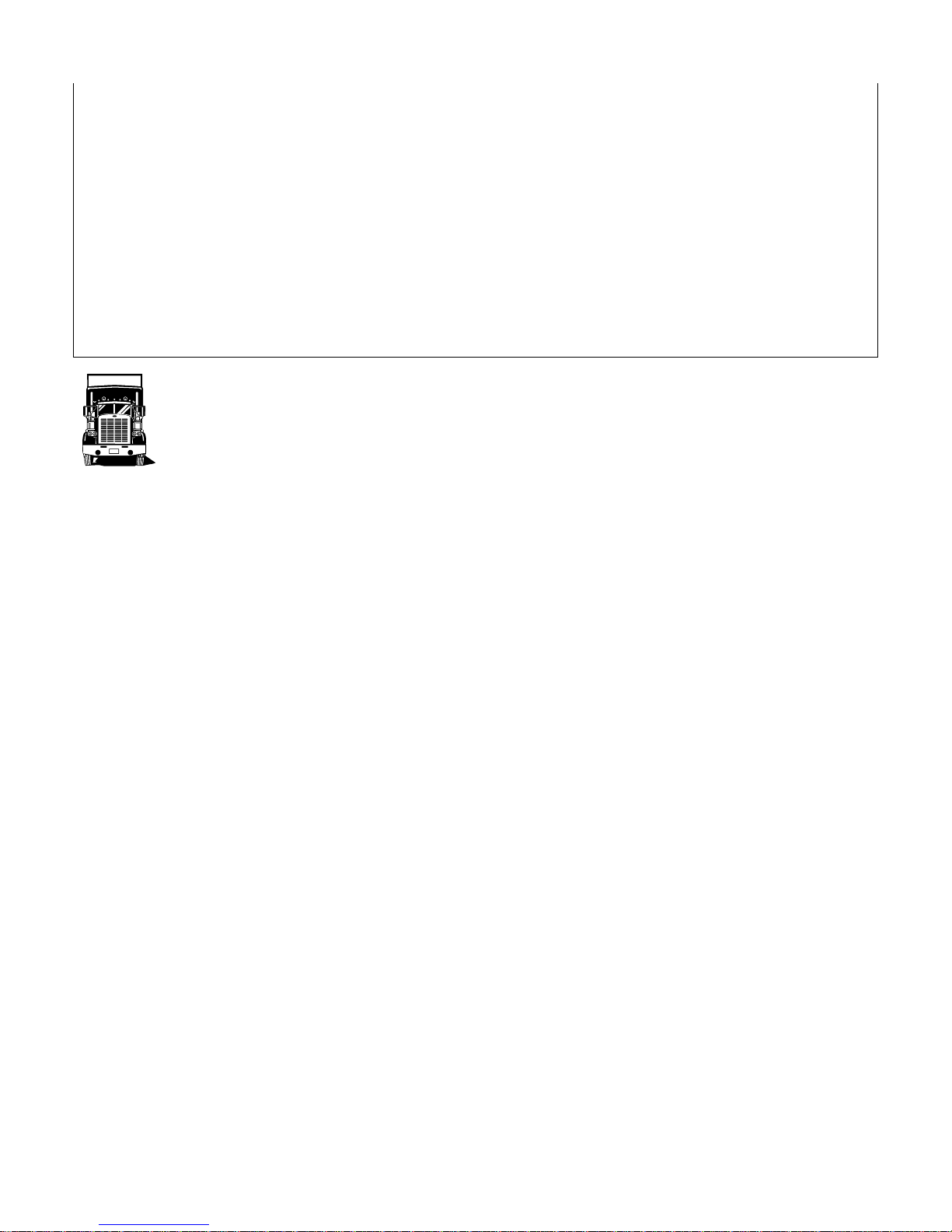
+ Transport in a wooden cage or case (ON REQUEST, WITH SURCHARGE)
The machine is wrapped into a thermo-plastic covering to assure the protection of all parts, then it is packed in a wooden
cage or case to protect it from collisions and possible bad weather.
To lift it, use a forklift (see picture 1). The machine is fixed inside the wooden packing by means of screws, to prevent it
from moving during the shipment.
You need to follow the indications you find on the packing before proceeding to moving or opening it.
WARNING
The size of the packing varies according to the machine ordered and its configuration.
WARNING
The machine is fixed to the packing by means of screws, so as to hinder that it can move during the transport (see
drawing in the following page)
DO NOT USE THE MOVABLE ARM WITH THE CONTROL PANEL AS LIFTING UP POINT.
In case of following manipulations, the machine should be displaced with the saw frame completely down and the movable
arm with control panel should turned inside just over the machine AND FIXED!.
9 - FITTINGS ASSEMBLING
INSTRUCTIONS FOR USE
BS400 SHIeng ED.2010 rev.00
11/45
The information necessary for the installation are given together with the fittings. Anyway you can find here following a
short description of the product, if it is not supplied.
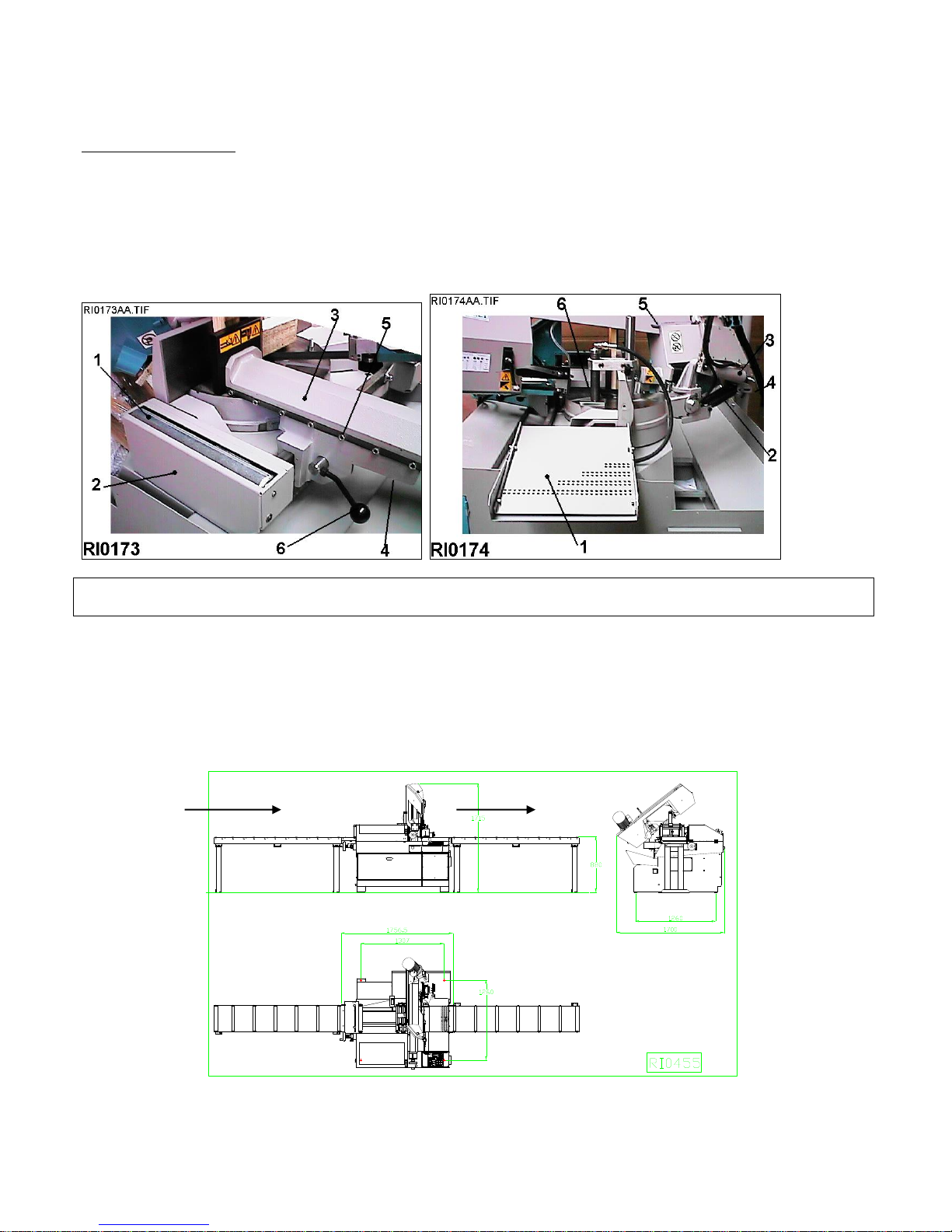
Supporting roller tables: for installing these accessories in the right way it is necessary first of all to level and fix the
machine. These can be connected on both sides (loading / unloading).
The machine is equipped with a connection for the loading roller table (on the left side) - pos.1 / dr. RI0173 -. For
connecting it with the first element - type RTS - (supplied as optional) it is necessary to take away the cover - pos. 2 / dr.
RI0173 - and the roller.
For connecting the unloading roller table (on the right side) you have to take out the inclined part of the chute - pos. 1 /
dr. RI0174 -, and replace it with the connection kit “RAB 40
S” - (supplied as optional); then connect the roller table (usually the RTS type).
Take as reference point the worktable and the support back jaw in order to aligne the roller tables starting from the one
that is nearest to the machine.
If you need very long pieces fix the legs of the roller tables on the ground and recycle the coolant transported by the
workpieces that have to be cut.
If your working process require it, on the unloading side you can choose to use the roller table with manual measuring
system with digital readout (RTL) or the one with digital measuring system and automatic positioning of the stop (RTP)
also.
INSTRUCTIONS FOR USE
BS400 SHIeng ED.2010 rev.00
12/45
Unloading Roller Table RTL with digital readout (Optional): it is like the RTS with the addition of a measuring device
equipped with digital readout, powered by one size A battery. It is available in 3- and 6-meter units to connect to the right
side of the saw.
Unloading Roller Table with motorized positioning RTP (Optional): it is comprised of the RTS roller table and a
motorized bar-stop. The blade movement can be synchronized with the ongoing control of the cutting lengths. Available in
3- and 6-meter units to be connected to the right side of the machine.
Inverter for variable blade speed - ESC - is an accessory which can be installed when manufacturing the saw and
allows the blade to have a variable speed. It can be adjusted by means of a selector located on the control panel.
In case the maximum power supply threshold is exceeded - for example, because of an excessive cutting pressure or
because the blade remains stuck into the material - the Inverter stops the motor. To restore it, the main switch has to be
turned to 0 (OFF), wait for about one minute and then turn it on I (ON).
In the meantime, try to find out the reason that caused the interruption and eliminate it.
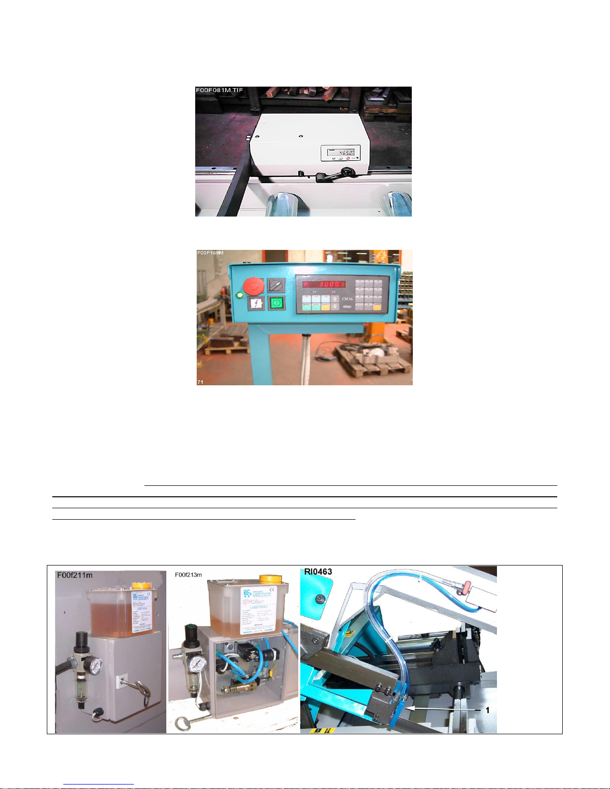
Minimal lubrication – THE MINIMAL LUBRICATION SYSTEM APPLIED TO THE BANDSAW ALLOW TO ELIMINATE
ALMOST COMPLETELY THE TRADITIONAL COOLANT SYSTEM. THE MATERIAL IS MUCH CLEANER AND THERE
IS NO WASTE/SPILLING OF COOLANT AND WATER, CONTRIBUTING THUS TO PRESERVING NON-RENEWABLE
ENERGY SOURCES AS WELL. IT IS ACTIVE ONLY DURING THE CUT.
IT IS COMPRISED OF A NOZZLE - 1/RI0463 – WITH 3 MICRO-HOLES TO SPREAD THE OIL ON THE BLADE, A
TANK WITH DEVICE TO ADJUST THE OIL FLOW AND ANOTHER TO REGULATE THE AIR PRESSURE. THE 24V
LOW TENSION SWITCH - 3/RI0462 – ALLOWS TO STOP IT AT ANY TIME AND GO BACK TO THE NORMAL
STANDARD COOLANT SYSTEM.

INSTRUCTIONS FOR USE
BS400 SHIeng ED.2010 rev.00
13/45
Standard adjustable bar stop - it will be fixed on the right side of the vice and it is useful for doing more cuts with the same
lengts.
Voltage transformer - place it between the electric equipment of the building and the electric supply of the machine. It
allows to work with a different voltage than the standard one (that is 400V / 50 Hz).
Available voltages: 230V, 460V, 500V, 575V.
Foot control – to be connected to the socket placed on the back side of the panel. By pushing it, the machine starts.
Vice pressure reducer - it allows to lower the working pressure of the closing jaws in comparison to the general pressure
of the system. It is a modular unit and it can be assembled on the saw at any time, between the valve-carrying base and
the hydraulic valve, on the hydraulic unit.
Supplementary vice – placed at the right side of the base, connected to the standard vice, allows to lock workpiece on
both sides of the cuts (only for 90 degrees cuts)
Hydraulic vertical vice - , located on the right side of the machine and of the main vice, helps to increase the clamping by
pushing the bar to the worktable until the cut has been completed.
10- BAND CHOICE -
In this paragraph we recommend the type of band to use for cutting an accordance to material that must be worked. To
get the best performance from this machine it is necessary to understand the right applications of the used tools and what
you have not to do with them.
The band you have to use must have the following dimensions (in mm.):
maximum length = 4040
minimum length = 4020
total height = 34 ( 1 ¼ inch )
thickness = 1,10
It is possible to use bands with a different thickness by changing appropriately the width of the pads guide “vv” (see the
paragraph ADJUSTMENTS ) and the tensioning of the band. It is also important the material of the band; it is generally
used the bi-metal band in different endurance qualities. The standard types are named M2, M48, M42, M51.
The endurance of the teeth increases - and the fragility too - by going from the materila M2 to the M51. There are also
blades with hard metal pads or with diamond dust.
For making a right cut it is necessary to choose the pitch (t) or THE NUMBER OF TEETH PER INCH (z). The blade
must have generally the toothing as follows:
- close toothing for cutting thin materials, tubular and profiles.
- thin toothing for cutting solid materials or pieces that need a long piece of band (for example the central part
of a profile "U" ), or for cutting softer materials as aluminium, copper, soft bronze.
By choosing the right one you can avoid a lot of working mistakes and you can get a good blade penetration and the
necessary space for the chips.
If you cut more pieces at the same time, you must consider them as one piece (that is you have to consider the
global size).
The enclosed table shows the necessary information for a right choice. It can also be updated or changed by the user
according to his personal experiences.
Even if there are toothings with constant pitch, most band sawing machines allow the use of bands with variable pitch
toothing - groups of teeth having different pitch one from each other, that reduce vibrations and noise and improve the
finishing and the capacity of removal.
SUGGESTED PITCH
SOLIDS
Outer
Diameter
(mm)
BIG
PROFILES
Wall
Thickness
(mm)
PROFILES
Wall Thickness
(mm)
BUNDLE
Lenght
to Cut
(mm)
REF.
VARIABLE
CONSTANT
14 M42
- - 1,5 max
-
10/14 M42
10 M42
- - 1 a 2
-
8/12 M42
8 M42
20 max
-
2 a 4
-

INSTRUCTIONS FOR USE
BS400 SHIeng ED.2010 rev.00
14/45
6/10 M42
6 M42
40 max
-
4 a 8
-
5/8 or 5/7 M42
5 M42
30 a 80
6 a 12
-
50 a 100
4/6 M42
4 M42
40 a 90
10 a 20
-
70 a 120
3 / 4 M42 o M51
3 M42 o M51
70 a 150
15 a 25
-
100 a 200
2 / 3 M42 o M51
2 M42 o M51
120 a 250
Oltre 25
120 a 300
These cutting recommendations are referred to 100 mm. diameter solid bar and a standard construction machine
of our range. For 2 speed machine we suggest you the motor speed to use; if it is into bracket ( ) it is better to use a
machine with ESC, that grant a continuous blade speed variation.
If material dimension decreases it is possible to increase the indicated values, considering also the machine model
and its performance and/or some optionals, for exemple ESC (Electronic Speed Control):
If material dimension increases it is necessary to decrease the indicated values, considering also the machine
model and its performance and/or some optionals, for exemple ESC (Electronic Speed Control):
MATERIAL
GROUP
i.e. DIN
denomination
DIN N°
Maximum
BLADE SPEED
m/min
Minimum
BLADE
SPEED
m/min
MOTOR
SPEED
(1or2)
FEED
FORCE
COOL
ratio
1)STRUCTURAL
STEEL
St37 St42
10037-10042
60
40
1.
BASSA
10%.
St50 St60
10050-10060
50
35 1 BASSA
10%
HARDENING STEEL
C10 C15
10301 10401
45
35 1 BASSA
15%
16MnCr5 20CrMo5
17131
17264
40
30 1 BAS/Med
10%
AUTOMATIC STEEL
9S20 10SPb28
10711
70
50
1 2
BASSA
15%
BEARING STEEL
100Cr6
13505
50
25 1 Med/ALT
5%
SPRING
65Si7
15028
40
30 1 Med/ALT
5%
2)TOOL STEEL
GG15 GG30
--
50
30 1 Med/BAS
dry
ALLOYED
AL99.5 GalSi15Mg
--
300
50 2 Med/BAS
2%
CuSn6 CuSn6Zn
--
120
200
40
50
2 1 2 Med/ALT
BASSA
2%
HIGH SPEED
C80W1
11525
11663
40
30
(1)
ALTA
5%
INOX STEEL
210Cr12 X155CrVMo
12080 12379
30
20
(1)
ALTA
dry
3)SPECIAL ALLOYS
X40CrMoV51
12344
30
20
(1)
ALTA
5%
S-6-5-2-2
13243
30
20
(1)
ALTA
5%
X5CrNi18 X10Cr1810
14305
30
20
(1)
ALTA
5%
TITANIUM
NiCr19NbMo
24668
20
15
--
ALTA
20%
NiMo30
24810
20
15
--
ALTA
15%
1)STRUCTURAL
STEEL
NiCr13Mo6Ti3
24662
20
15
--
ALTA
15%
Ti1
37025
30
20
(1)
ALTA
10%
G-TiAl6V4
37164
35
20
(1)
ALTA
10%
 Loading...