

IMES S1010 Mk4 Installation & Operating Manual
Prince of Wales Road Tel: + 44 (0) 114 284 1840
Sheffield www.imesint.co.uk
S9 4DZ
United Kingdom
Panel mounting ASCII display
S1010 Mk4
Installation & Operating Manual
Caution: There is a risk of electrical
shock if this instrument is not properly installed
Caution: Risk of danger: Read the whole
manual before you install this meter
Software version F04.01
Dated: 1 May2016
!
Revision:1
1

.
Warranty
We warrant this product against defects in materials or workmanship for a period of three
(3) years from the date of purchase.
In the event of a defect during the warranty period, the unit should be returned, freight (and
all duties and taxes) prepaid by the Buyer to the authorised distributor from where the unit
was purchased.
The Distributor, at its option, will repair or replace the defective unit. The unit
will be returned to the Buyer with freight charges prepaid by the distributor.
LIMITATION OF WARRANTY
The foregoing warranty shall not apply to defects resulting from:
1. Improper or inadequate maintenance by the buyer.
2. Unauthorised modification or misuse.
3. Operation outside the environmental specification of the product.
4. Mishandling or abuse.
The warranty set forth above is exclusive and no other warranty, whether written or oral is
expressed or implied. We specifically disclaim the implied warranties of merchantability
and fitness for a particular purpose.
EXCLUSIVE REMEDIES
The remedies provided herein are the buyer’s sole and exclusive remedies.
In no event shall we be liable for direct, indirect, incidental or consequential damages
(including loss of profits) whether based on contract, tort or any other legal theory.
2

Contents
Warnings 4
Introduction 5
General Description 6
Panel mounting & Installation - Class II 7
Wiring Advice 8
Connections 9
Installation hints for best performance 10-11
Application Notes 12
Language Selection 13
Display Brightness 14
Display Modes 15
Serial Data settings 16-17
Logic Input functions 18
Logic Input connections & Front Buttons 19
Factory defaults 20
Calibration Audit number 20
Scale Factor adjustment 21
Offset Adjustment 22
Menu Timeout adjustment 23
Reverse / Mirror display setting 24
Bootup Routine choices 25
Multi Memory MEM option 26
Error Codes and fault finding 27
Output Options - installing 28
WEEE 29
Equipment Specifications 30
Record of Revisions 31
ASCII Hex codes and displayed characters 32
Signal Levels 33
Special data commands 34
Declaration of Conformity 35
Separate manuals for options
Alarm option settings See Alarm manual *
Analogue output option settings See Analogue manual *
Serial output option settings See Serial manual *
Real Time Clock setting See Serial manual *
* Need a manual urgently?
You can download manuals from our website.
3
Warnings
Please carefully read this manual and all warnings. Install the meter ONLY when you are sure
that you’ve covered all aspects.
Where the product is intended for “UL” installations, removal or
!
!
addition of option boards is not permitted.
Check that the model number and supply voltage suit your application before
you install the meter.
Connect the meter according to current IEE regulations, IEC61010 &
NFPA:70 National Electric Code in USA.
This meter is for Installation class II service only. This means it
has exposed electrical and power terminals. You must install it in a
suitable fire enclosure which will also protect users from electric shock
!
!
!
We designed this meter for Pollution-Degree 2 environments only.
Power supplies to this equipment must have anti-surge (T) fuses rated at 400mA for
230V supply, 400mA for 110V supply or 2A for DC supplies in the range 11-30VDC.
Only Siba fuses in series 189500, cULus listed according to file #E167295 are
accepted for this service under the terms of UL listing. A switch or circuit breaker, clearly
marked as a disconnecting device, must be included close to the installation.
Don’t touch any circuitry after you have connected the meter, because there may be
lethal voltages on the circuit board.
Only adjust on-board switches or connections with the power turned off
Make sure all screw terminals are tight before you switch the meter on.
Only clean the meter’s front with a soft damp cloth. Only lightly dampen with water.
!
Safety First ..............Don't assume anything............. Always double check.
If in doubt, ask someone who is QUALIFIED to assist you in the subject.
4
Do not use any other solvents. The behind-panel case may be cleaned with a dry cloth
only, use no liquid or solvent on it.

Introduction
Please contact us if you need help, if you have a complaint, or if you have suggestions to help
us improve our products or services.
If you contact us about a product you already have, please tell us the full model number and
serial number, so that we can give you accurate and fast help.
This product has a 3 year warranty. We will put right or replace any meter which is faulty
because of bad workmanship or materials. This warranty does not cover damage caused by
misuse or accident.
If you return a unit for repair, please include a detailed description of the problem, and the
name of a contact who we can refer to for any questions. Please mark for the attention of the
QA Department.
IMPORTANT
If this equipment is important to your process, you may want to buy a spare to cover possible
failure or accidental damage in the future.
This is because during factory shutdown periods, you may have to to wait several weeks for
an equivalent replacement, or we may have no stock at the time you urgently need it.
You may also need to pay extra carriage charges if you want a fast, guaranteed courier service.
Warranty repairs or replacements are usually returned with a standard courier service.
We do not offer compensation for losses caused by failure of this instrument.
We thought you’d prefer to know about possible delays and extra charges now, rather than
during a panic. A spare unit could help to avoid these issues.
We always try to improve our products and services, so these may change over time. You
should keep this manual safely, because future manuals, for new designs, may not describe
this product accurately.
We believe these instructions are accurate, and that we have competently designed and
manufactured the product, but please let us know if you find any errors.
5
General Description
This series of meters accepts industrial sensors to allow various physical measurements to
be made, such a weight, temperature, pressure, humidity etc. Different models are available
for different sensor types.
The main function of this series is to give a numeric readout of the variable being monitored.
Most models include an excitation power output, to power the sensor directly.
Various optional output modules are also available to give alarm relay outputs, analogue
output or digital communications, or any combination of these options.
Meters are programmed using front panel pushbuttons. The buttons may be locked with a
rear switch.
Meters have two power supply options : 100-240 VAC or 11-30VDC
These meters are designed to mount into a protective enclosure which will protect users from
contact with power and signal wiring.
These units must be installed fully assembled, and must be installed according to local electrical
installation rules. When properly installed, they provide ingress protection to IP65 / NMA4X
from the front
Safety
Caution: There is a risk of electrical
shock if this instrument is not properly installed
Caution: Risk of danger: Read the whole
!
manual before you install this meter
Obey all safety warnings in this manual, and install the meter according to local wiring and
installation regulations. Failure to follow these guidelines may cause damage to the meter,
connected equipment, or may be harmful to personnel.
Any moving mechanical device controlled by this equipment must have suitable access guards
to prevent injury to personnel if the meter should fail.
6
Panel Mounting and Installation - Class II
Install the meters in a suitable protective electrical control enclosure according to local wiring
regulations. See specifications for maximum allowable temperature in enclosure. Allow
adequate air circulation.
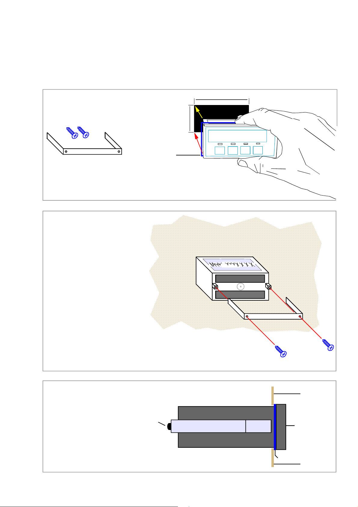
Installing into front of panel
Remove the two rear bracket
screws and safely store them
and the U-Bracket for later fitting.
Bracket screws
U-Bracket
45mm +1mm -0mm
Securing into the panel
Re-fit the U-Bracket and tighten the bracket
screws to firmly clamp the meter in place.
Check that the gasket is evenly pinched
between the meter’s front bezel and the
enclosure front
Ventilation
There should be sufficient ventilation in the
enclosure to ensure that the meter’s case is
always kept to less than 60C.
Gasket
92mm +1mm -0mm
Panel cutout
888888
Slide the meter, with gasket
into the panel cutout
Meter Spacing.
Meters should be spaced apart sufficiently
to allow a free flow of ventilation air around
the meters, such that no part of the case will
exceed 60C
Side view of meter installed in panel
Bracket screw (1 of 2)
Left side of meter case
U-Bracket
U-Bracket
Gasket
Bracket screws
Front surface
of enclosure
Front surface
of meter
Front surface
of enclosure
7
Wiring Advice
This meter uses detachable screw terminal connectors. Refer to the wiring diagram on the
following page for the correct positioning of each wire.
The conductors you use must be suitable for the meter’s temperature, current and voltage
rating, which is broadly described as follows:-
Cable Temperature Rating
All cables must be rated for operation up to 90C continuous.
Cable gauge and screw tightness
The connectors on this instrument can accept conductors up to 16 gauge AWG / 1.5mm
c.s.a. The minimum cross sectional area shall be 22 gauge AWG / 0.5mm2 . Tighten screw
terminals to 7.0 lb/in torque / 0.8 Nm torque.
Cable insulation voltage rating
Cables shall have an insulation voltage rating of at least 380V continuous.
2
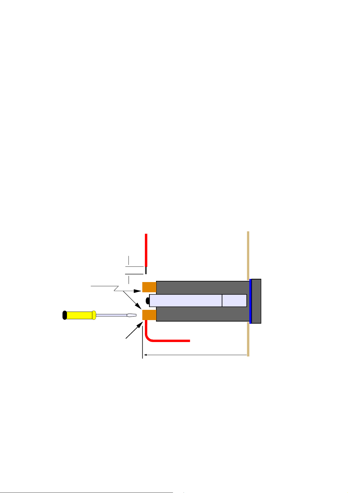
Wire preparation:
Outside
enclo sure
Strip back
5mm max.
Detachab le
connectors
Terminal screwdiver - 3mm blade
No bare wires exposed
Insid e
enclo sure
Side view of meter
U-Bracket
125mm behind panel
We recommend multi-strand wire, because it withstands vibration better than single strand
cable. Pull the wire firmly after you make the connection to confirm it is tight.
Use screened cable for all signal and control wiring and connect the screen to earth at the
destination end only. Route signal cabling away from power cabling and relay switching
cabling, to avoid electrical noise interference.
8
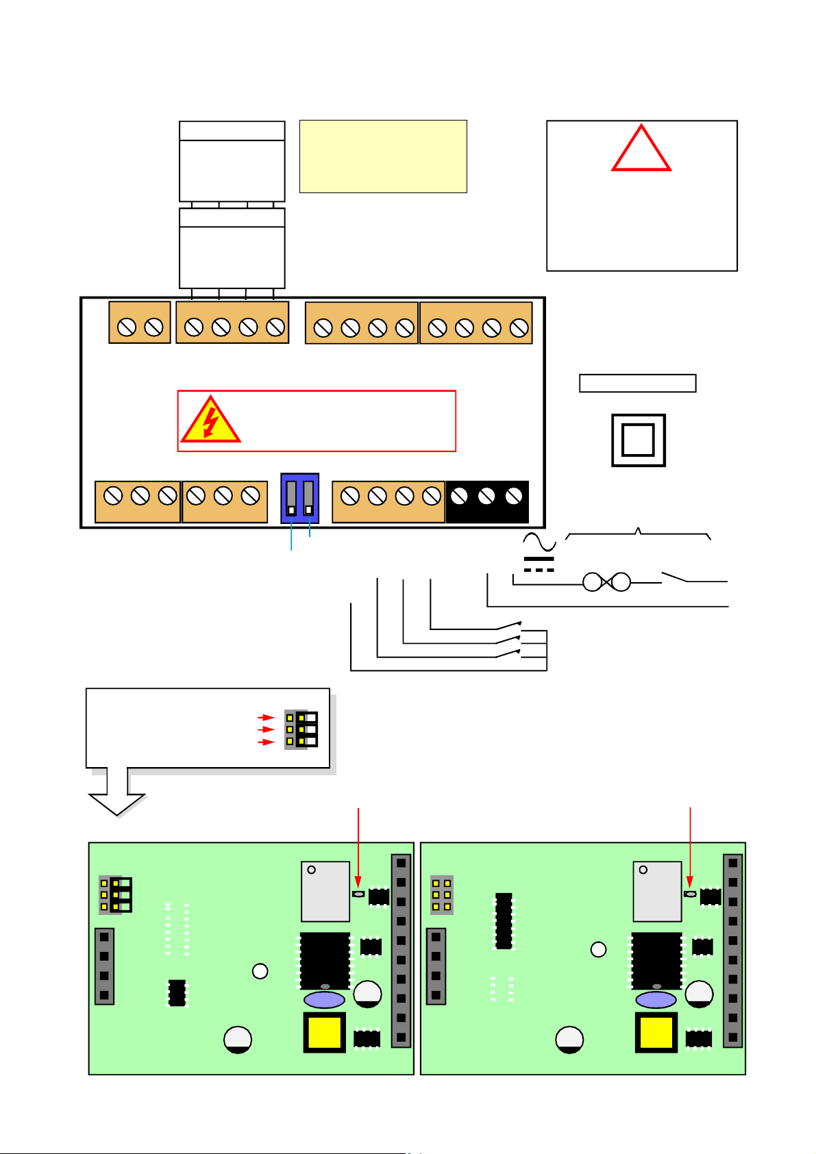
Connections
R S 2 3 2
TxD
RxD
Comm
Enable is used in mode C1
to activate or de-activate the
RS232 or RS485 serial output.
Connect to Comm to continually
transmit data.
Enable
R S 4 8 5
Rated 2A 250VAC Resistive
B
A
Comm
- +
14 15 16 17 18 19 20 21 22 23 24 25 26 27
Analog
o/p option
Serial Data
o/p option
Enable
Warning:
Disconnect all power before
exposing the rear of the meter
Signal I/P & Excitation
1 2 3 4 5 6 7 8 9 10 11 12 13
AL1 AL2 AL3 AL4
0, 2 or 4 Alarm Relay
o/p options
Logic Inputs Power
!
Connectors and options
Connectors may be present
even if output options are not
installed. Refer to rating label
to see installed options.
Class II Installation
Customer-supplied disconnection
and overload protection devices
nil
nil
Demand
Common
Data B- /Txd
Data A+/Rxd
Alarm Lock
Bias +5V on Sig B
Bias 0V on Sig A
120 Ohm termination resistor
C
B
A
Solder Switch closed
RS485 Version (IC4 missing)
9122-0670 P4
C
B
A
IC4
N L
CC.1
CC.2
CC.3
- +
Not used
Common
Calib’n Lock
Remo te
contacts
(5V DC 1mA)
Circuit breaker
Fuse Switch
Power
Solder Switch closed
RS232 Version (IC3 missing)
9122-0670 P4
IC4
IC3
IC3
9
Installation hints for best performance
This section offers several suggestions which will help you get the best performance from
your system.
RS232 and RS485 use comparitively small signals which can easily be corrupted by the
potentially high level of electrical noise which can be created by electrical machinery such as
motors, welding systems, discharge lighting, AC power inverters and solenoids. These steps
will ensure you get the best possible performance from your system.
RS232 has limited capability over long cable distances, due its low driving power (which
causes the signal to reduce in level as cable length increases) and single ended signal (which
is prone to interference by local electrical noise) , as shown below...
Maximum recommended cable distances if using LOW
capacitance screened cable such as CAT5 cable.
Baud Rate RS232 RS485 or RS422
1200 50m 1200m
9600 20m 150m
19200 10m 75m
38400 5m 30m
115200 2m 10m
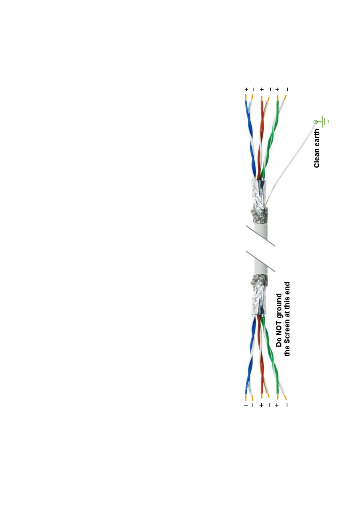
1. Use good quality screened signal cable, with twisted pairs. Screened twisted pair
CAT5 cable is ideal. The screen should be earthed at the display end only.
2. If you are using multi-pair twisted cable, each pair should be dedicated to a single
display as shown opposite, for maximum noise immunity.This will ensure that any
electrical noise induced in the cable is properly cancelled. Mixing destinations
carelessly amongst the twisted pairs can easily corrupt data.
3. The cable should be routed away from noisy wiring and devices such as power
feeds from inverters, discharge-lighting cables, welder cabling etc, and should
preferrably be routed in a dedicated low voltage signalling/instrumentation conduit
or cable tray.
4. If you want to simulate data, a useful free terminal, with good flexibility is
RealTerm, available from http://sourceforge.net/projects/realterm/
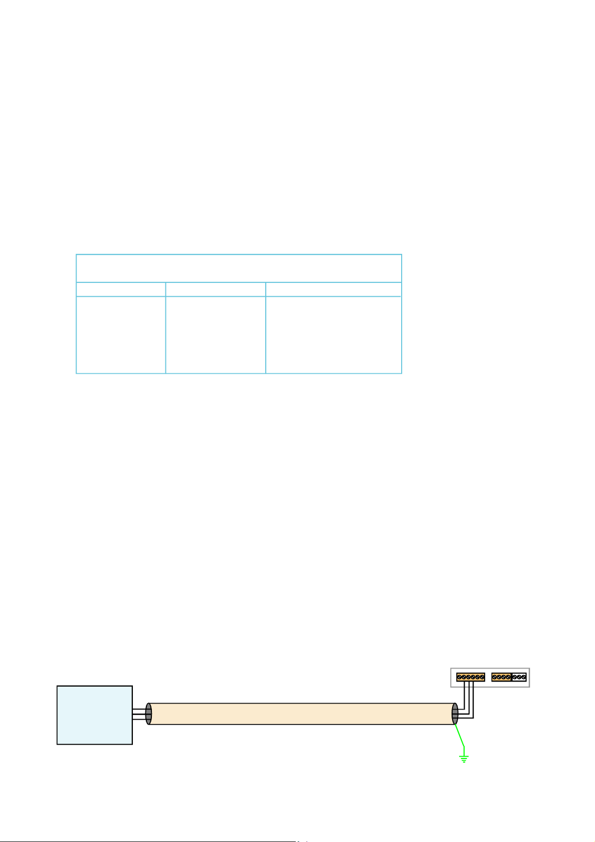
Signal Input
Logic Input
Power Input
RS232 or
RS485
transmitter
Do not
connect
screen at
this end.
Sender connections
10
Length of screened cable
Connect screen
to earth ONLY
at this end.
Clean Earth
Display connections
Display 1
Display 2
Display 3
Displays
Data 1
Data 2
When using multi-core screened cable to connect several displays to several data sources, please be sure to use one twisted
pair for each display and sensor.
Do NOT use a wire from one pair for signal positive and a wire from another pair for signal negative, as this will prevent the
twisted cables form cancelling any induced electrical noise, and can couple noise from one source to another.
Data 3
Data Sources
11
 Loading...