

IMES EPM-XP Operation Manual & Technical Manual

Operation manual EPM-XP
Software Release l.0.5.17 2019-01-29
Page 1 of 50

Operation manual EPM-XP
Software Release l.0.5.17 2019-01-29
Page 2 of 50
Content
1
Introduction ___________________________________________________________ 4
1.1 General __________________________________________________________________ 4
1.2 Other products from IMES __________________________________________________ 4
1.3 IMES-Service _____________________________________________________________ 4
2
Scope of supply ________________________________________________________ 5
3
Important information __________________________________________________ 5
3.1 Use of the operator manual __________________________________________________ 5
4
Description ___________________________________________________________ 5
4.1 Introduction ______________________________________________________________ 5
4.2 Measure functions _________________________________________________________ 6
4.3 Functional description ______________________________________________________ 6
5
Operation _____________________________________________________________ 7
5.1 Operator push buttons _____________________________________________________ 7
5.2 Operating functions ________________________________________________________ 8
5.3 Installation of visualisation- and USB driver software ____________________________ 9
5.1 Installation of reference curves for selected load of MAN B&W MC-C engines ______ 10
5.2 Start visualisation software _________________________________________________ 10
5.3 Selection of COM port on PC _______________________________________________ 11
5.4 Charge battery ___________________________________________________________ 11
5.5 Change battery ___________________________________________________________ 12
5.6 Mounting instructions on 2-stroke engines ____________________________________ 13
5.7 Measurements with EPM-XP _______________________________________________ 13
6
Visualisation software release 1.0.5.17 ____________________________________ 14
6.1 Main tool bar buttons _____________________________________________________ 14
6.2 Load measured data from EPM-XP to PC ____________________________________ 15
6.3 Load measured data from hard disc to PC ____________________________________ 15
6.4 Monitoring of combustion data _____________________________________________ 16
6.4.1 Screen page “Cylinder pressure curve” _____________________________________________ 16
6.4.1.1
Indication of cylinder pressure (single) versus volume _____________________________ 16
6.4.1.2
Indication of all cylinder pressure (all) versus crank angle __________________________ 17
6.4.1.3
Zoom -function ___________________________________________________________ 17
6.4.1.4
Cross On function _________________________________________________________ 18
6.4.1.5
Save as ASCII ____________________________________________________________ 18
6.4.1.6
Deviations for automatic Pcomp calculation on two-stroke engines ___________________ 19
6.4.1.7
Save shifted curves ________________________________________________________ 21
6.4.1.8
Delete measurement on EPM-XP _____________________________________________ 21

Operation manual EPM-XP
Software Release l.0.5.17 2019-01-29
Page 3 of 50
6.4.1.9
Open *.csv files at Excel ____________________________________________________ 22
6.4.2 Screen page “Engine report” _____________________________________________________ 22
6.4.3 Screen page “Pmax diagram” _____________________________________________________ 23
6.4.4 Screen page “Pmax Balance” _____________________________________________________ 23
6.4.5 Screen page “Pcomp Balance” ____________________________________________________ 24
6.4.6 Screen page “IMEP” ____________________________________________________________ 24
6.4.7 Screen page “IMEP balance” _____________________________________________________ 25
6.4.8 Screen page “Performance” ______________________________________________________ 25
6.4.9 Screen page “Remarks” _________________________________________________________ 26
6.4.10 Screen page “Engine data” _______________________________________________________ 26
6.4.10.1 Calculation of effective Power (= shaft power)___________________________________ 27
6.4.10.2 Indication of effective Power in screen page “Engine report” _______________________ 28
6.4.11 Pipe oscillation filter ____________________________________________________________ 28
6.5 IMEP- and IPOWER calculation ____________________________________________ 29
6.5.1 Application on two-stroke engines _________________________________________________ 29
6.5.1.1
Load measured data from hard disc to PC _______________________________________ 29
6.5.1.2
Enter scavenge air pressure of selected load _____________________________________ 30
6.5.1.3
Indication of IPOWER and IMEP on screen page “Cylinder” _______________________ 30
6.5.1.4
Indication of IPOWER and IMEP on screen page “Engine report” ___________________ 31
6.5.1.5
“Auto shift” function _______________________________________________________ 31
6.5.1.6
Select a curve as reference curve _____________________________________________ 31
6.5.1.7
Save a reference curve ______________________________________________________ 32
6.5.1.8
Open reference curve for to optimize TDC position of other cylinder _________________ 32
6.5.1.9
Open reference curves of selected load for MAN B&W MC-C engines _______________ 32
6.5.1.10 Compare actual measurements with reference curve ______________________________ 32
6.5.1.11 Save shifted curves ________________________________________________________ 33
6.5.1.12 Example for optimum TDC position on MAN B&W MC-C engines __________________ 34
7
Free internet software download _________________________________________ 41
8
Accuracy check _______________________________________________________ 41
8.1 Connection of EPM-XP to pressure calibrator _________________________________ 42
8.1 Generate pressure at pressure calibrator _____________________________________ 43
8.2 Example of displayed EPM-XP values during pressure check ____________________ 44
8.3 Disconnect EPM-XP from pressure calibrator _________________________________ 44
9
Cleaning ____________________________________________________________ 45
9.1 Periodically cleaning ______________________________________________________ 45
9.2 Cleaning in case of hard deposit _____________________________________________ 45
9.3 Cleaning procedure of adaptor ______________________________________________ 46
9.4 Cleaning procedure of cylinder pressure sensor _______________________________ 46
10 Check tightening of sensor on adaptor ____________________________________ 47
11 Basic check for fault finding ____________________________________________ 48
12 Nomenclature ________________________________________________________ 49
13 Technical data ________________________________________________________ 49
14 Warranty ____________________________________________________________ 49
15 IMES Sales and service organization _____________________________________ 49
16 Declaration of conformity _______________________________________________ 50
Operation manual EPM-XP
Software Release l.0.5.17 2019-01-29
Page 4 of 50
1 Introduction
1.1 General
Thanks for choosing this IMES quality product. You
receive a product, which features technical innovation,
high accuracy, reliability and a very long lifetime
1.2 Other products from IMES
IMES offers a variety of products for the application
of cylinder pressure measurement:
- HTT Cylinder pressure sensor
- CPS Cylinder pressure sensor
- IPT Injection pressure sensors
- Compri Compression pressure tester
- CMS Combustion monitoring system
1.3 IMES-Service
For all specific questions which you may have after
studying this manual, we would be pleased to offer our
service to you and to advise you on application specific
problems to achieve optimum results.
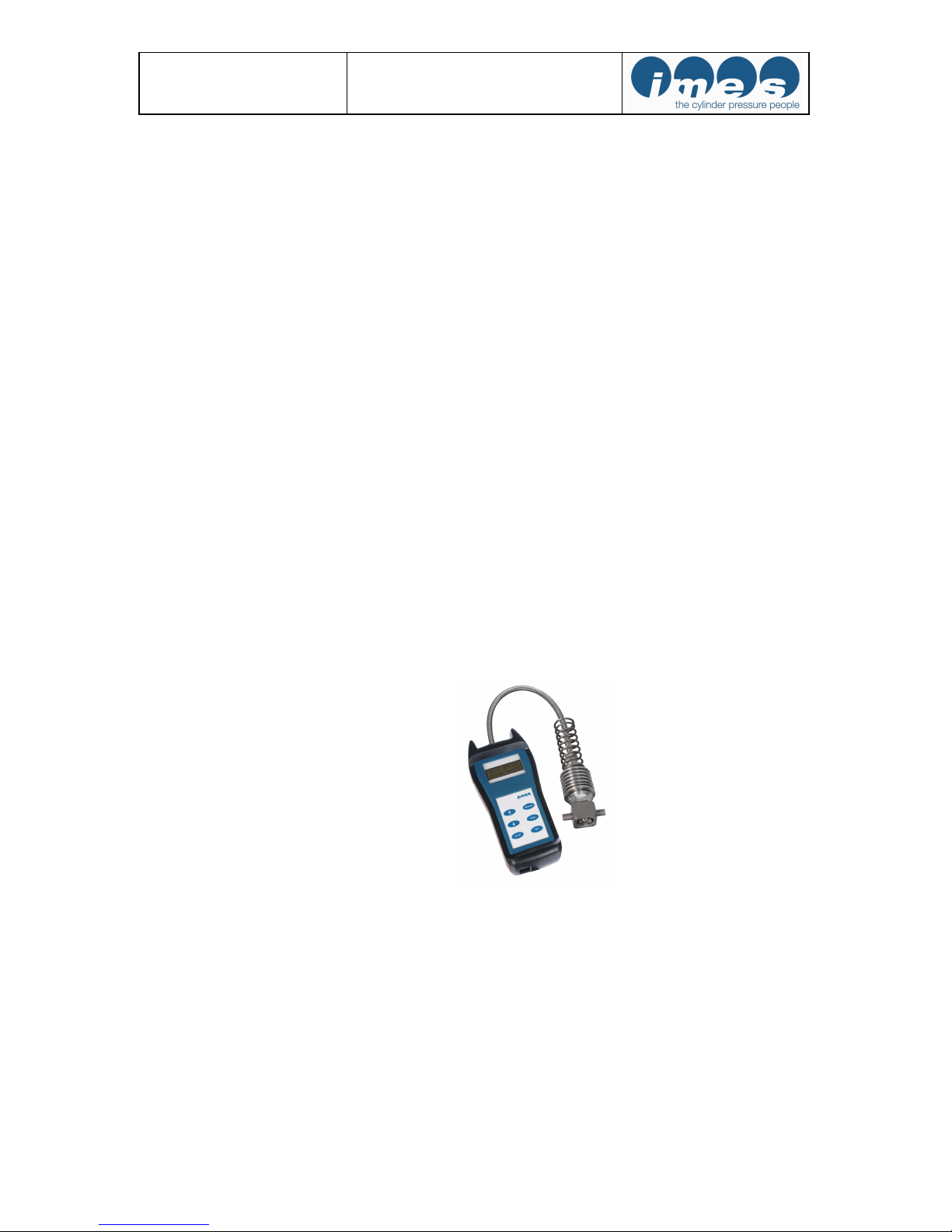
Fig. 1: EPM-XP Electronic indicator
Operation manual EPM-XP
Software Release l.0.5.17 2019-01-29
Page 5 of 50
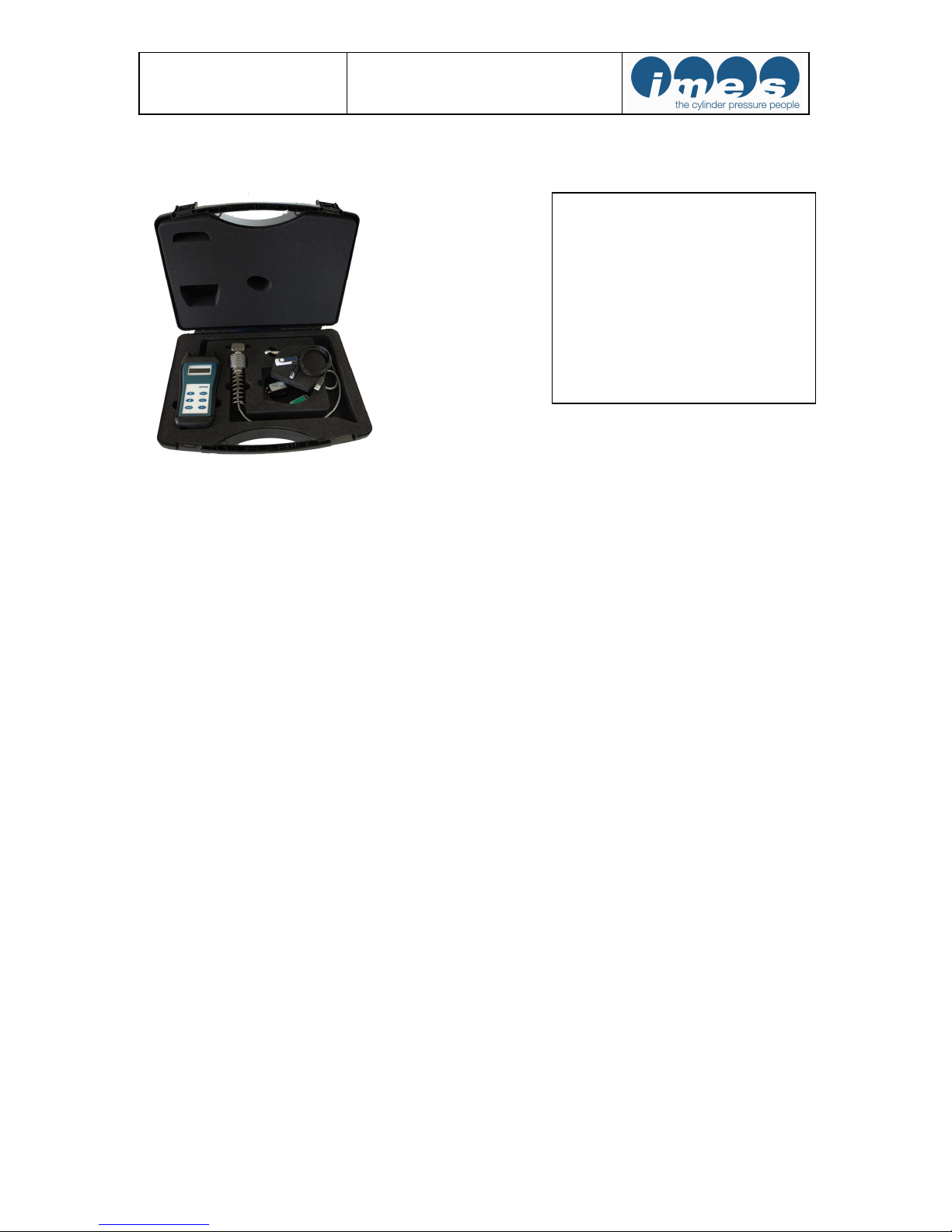
2 Scope of supply
Fig.2: Instrument case with all components
3 Important information
Please study this manual carefully, before using the
equipment. This will ensure that you will receive maximum
benefits from using this engine performance tuning tool with
its versatile functionality and it will guarantee optimum
benefits over its lifetime.
3.1 Use of the operator manual
We strongly recommend you to read the complete manual
before using the equipment. If you have already experience
with IMES systems you may only read the relevant
chapters for the required information.
It was our intention to structure this manual in a clear
layout, to enable you to get easy and instant access to the
information you are looking for. Please keep this manual in
a safe place where it is always available for easy access.
We ask for your understanding, that we will reserve the
right to change information and instructions in this manual
if necessary without giving notice in advance.
4 Description
4.1 Introduction
The electronic indicator EPM-XP is a handy-, battery
powered-, portable device to measure and evaluate cylinder
pressure on diesel engines at speed up to 1500 RPM.
The EPM-XP collect 10 consecutive pressure measurements (cycles) and calculates peak pressure, engine speed.
The measured data are displayed in numerical format on the
LCD screen and can be stored.
- 1 x EPM-XP incl. cylinder
pressure sensor and adaptor
- 1 x Dongle (USB)
- 1 x USB cable
- 1 x USB stick incl.
visualisation software and
documentation
- 1 x tool
- 1 x quick step manual printed
- 1 x calibration certificate
- 1 x instrument case

Operation manual EPM-XP
Software Release l.0.5.17 2019-01-29
Page 6 of 50
Up to 160 measurement data sets can be stored in the
EPM-XP. The stored data can be downloaded via USBinterface to a personal computer for evaluation.
The scope of supply includes software for Windows which
allows additional evaluation and visualization of the
collected data.
4.2 Measure functions
Pmaxmean: average maximum pressure
Pcomp: Compression pressure (only on two stroke
application)
RPM: engine speed
A complete individual pressure curve (or an average over
the selected number of cycles) will be stored in the
EPM-XP memory with each measurement.
4.3 Functional description
The cylinder pressure will be measured with the EPM-XP
unit incl. high temperature pressure sensor at indicator cock
on marine diesel engines.
Memory : 160 data sets
Application 2 – stroke: 40 – 300 RPM
Application 4 – stroke: 200 – 1500 RPM
The battery must be re-charged after approximately one
hour of continuous operation.
Operation manual EPM-XP
Software Release l.0.5.17 2019-01-29
Page 7 of 50
5 Operation
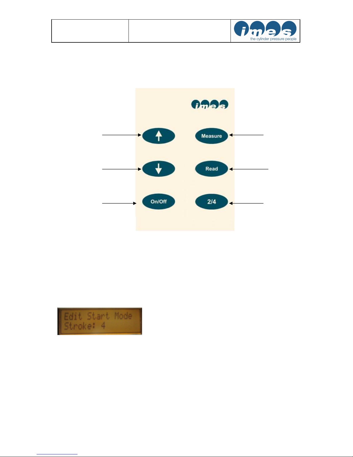
5.1 Operator push buttons
Remarks: After switching “On“ the EPM-XP display automatically shows application on 2-stroke engines.
For automatic 4-stroke engine mode selection after switch „On“ the user must connect the EPM-XP via USB
cable to PC.
Press “Read“ and “Measure“ for automatic 4-stroke engine mode selection.
After display unhand immediately the push buttons to get selected mode.
If user is in 4-stroke mode the EPM-XP can be switched to automatic 2-stroke mode selection after switch „On“
the user must connect the EPM-XP via USB cable to PC.
Press “Read“ and “Measure“ for automatic engine selection to start mode 2-stroke.
Fig. 3: Push buttons
Arrow up “↑“
Arrow down “↓“
On/Off
Start measurement
Read measurement
Selection of
2- or 4-stroke engine
and selection of load on
two-strokes
Operation manual EPM-XP
Software Release l.0.5.17 2019-01-29
Page 8 of 50
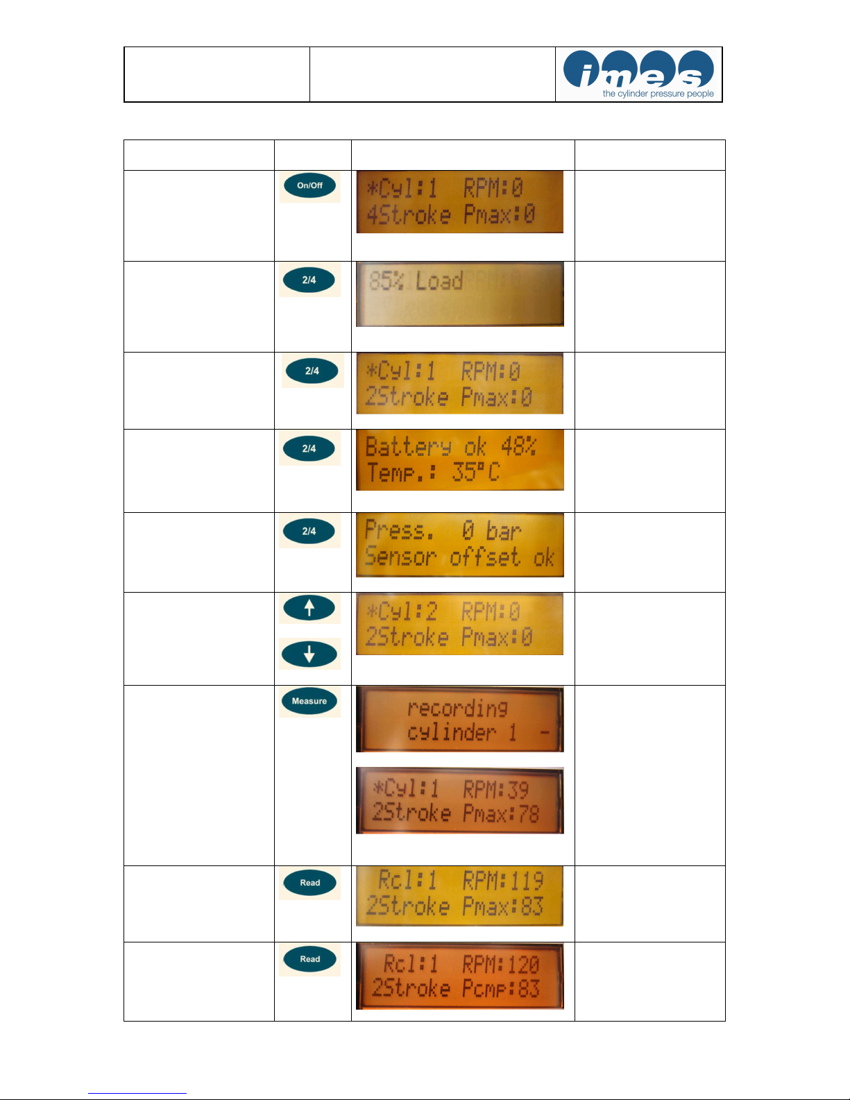
5.2 Operating functions
Function Key board
push button
Display Notes
Switch On/Off
Basic settings will be displayed after switching on:
Cyl:1 = cylinder no.1
2 stroke = 2 stroke engine
4 stroke = 4 stroke engine
Pmax in bar ; RPM: speed
Selection of load on 2stroke engine
Push key “2/4“ for to set-
up load mode for measure-
ment. Steps: Load unde-
fined, 25 %-, 50%-, 75%-
,85%-, 90%-, 100%-,
110% load
Selection of 2 -stroke or 4
–stroke engine
Push key “2/4“ and
change mode of operation
to the desired value (4 or
2 stroke application).
Battery check
Push key “2/4“ two times
to check the battery status.
Also temperature at mea-
suring element will be dis-
played.
Sensor check
Push key “2/4“ three
times to check the sensor
status at 0 bar.
Selection of cylinder
Push arrow key “
↑
↓
“ and
change the displayed value
to the number of the
selected cylinder.
Start measurement
During measurement the
following information
“Recording cylinder” will
be indicated.
Display indication (1-2 s)
of measured cylinder
values. Then EPM-XP
unit switches auto-
matically to the next
cylinder.
Read Pmax
The measured value for
Pmax of the selected
cylinder will be displayed.
Read Pcomp (only on two
stroke engines)
Press 2x
The measured value for
Pcomp of the selected
cylinder will be displayed
Operation manual EPM-XP
Software Release l.0.5.17 2019-01-29
Page 9 of 50
5.3 Installation of visualisation- and USB driver software
The scope of supply includes the IMES visualisation software on USB stick for displaying and analysing the
measured data in numeric and graphic format.
Hardware and software requirements
:
IBM PC Pentium or 100 % compatible, USB port
Windows 7, XP
Main memory minimum 16 MB RAM,
VGA-monitor with minimum resolution of 1024 x 768 pixel.
Install USB stick on your Personal Computer. Open directory software and make a double click at setup.exe for
installation of visualisation- and necessary USB driver software.
The program will install automatically a directory at hard disc and places an icon on the desktop of your
computer.
Function Key board
push button
Display Notes
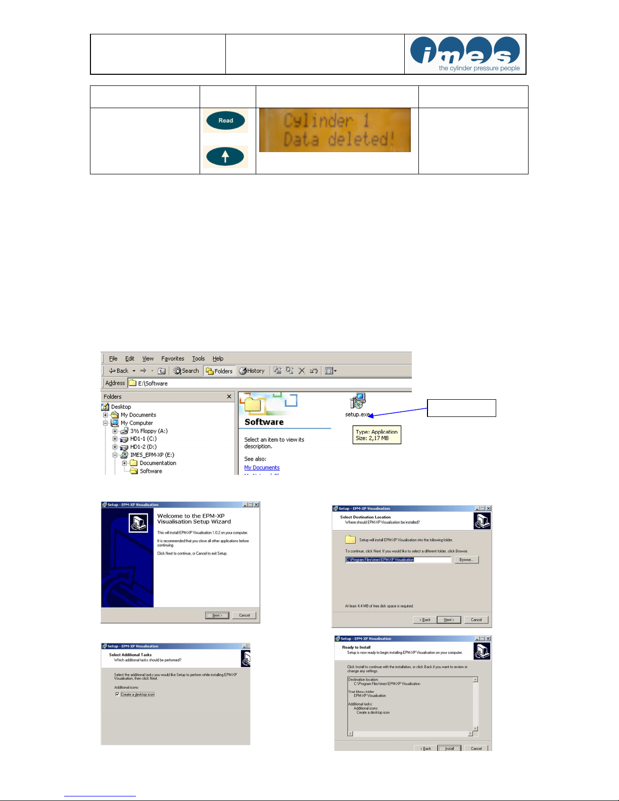
Delete measurements
+
Push “Read” and “↑“
at the same time for 2s to
delete the currently displayed measurement.
Double click

Operation manual EPM-XP
Software Release l.0.5.17 2019-01-29
Page 10 of 50
USB driver will be installed automatically
Press enter to finalize USB driver installation
5.1 Installation of reference curves for selected load of MAN B&W MC-C
engines
5.2 Start visualisation software
Fig.4: USB Dongle IW 1556
Before starting visualisation software please install EPM-XP ISL Dongle (fig.4) on USB port of PC
EPM-XP Visualisation.lnk
Start visualisation software
by double click on icon

Operation manual EPM-XP
Software Release l.0.5.17 2019-01-29
Page 11 of 50
5.3 Selection of COM port on PC
For selection of COM Port the EPM-XP should be
connected via USB cable to PC
• Switch on EPM-XP
• Connect USB port of PC via USB cable to EPM-XP
• Run “Visualisation software“ with double click on
the desktop icon.
Fig.5: EPM-XP connected via USB cable to PC
For selection of COM Port the EPM-XP should be connected via USB cable to PC and visualisation software
should started with double click on desktop icon.
With mouse click on “Tools” and selection “Interface” the COM port of PC will be selected.
5.4 Charge battery
The EPM-XP has a re-chargeable battery. The battery
charging will start automatically after the EPM-XP unit
has been connected via USB cable from USB port to PC
(fig. 6,7,8,9)
Fig. 6: Indication during charging process Fig. 7: USB-port of EPM-XP
Fig. 8: Indication charging process completed Fig. 9: EPM-XP connected via USB cable to PC
USB por
t
Operation manual EPM-XP
Software Release l.0.5.17 2019-01-29
Page 12 of 50
Note: The battery must be charged at least minimum two hours before its first usage.
Do not change battery during charging process while EPM-XP is connect via USB cable to PC.
When the EPM-XP is connected by USB, the battery charging runs automatically. The indicator can detect the
charging status and continues charging until the battery is fully loaded. Then the charging process stops
automatically. It is not recommended to interrupt the charging process before it is automatically stopped. The
charging process is finished when the display message "EPM-XP charging..." disappeared.
If the battery status is low and the charging process stops after 5-10 minutes, then the user can manually force
the unit to charge the battery for 90 minutes by pressing both arrows + at the EPM-XP unit for
2 seconds (Forced Charging Mode).
Note: It is not recommended to use the Forced Charging Mode when the battery charge condition is more than
40%, due to the risk of overcharging. Please see chapter 5.2 for a description how to check the charge state.
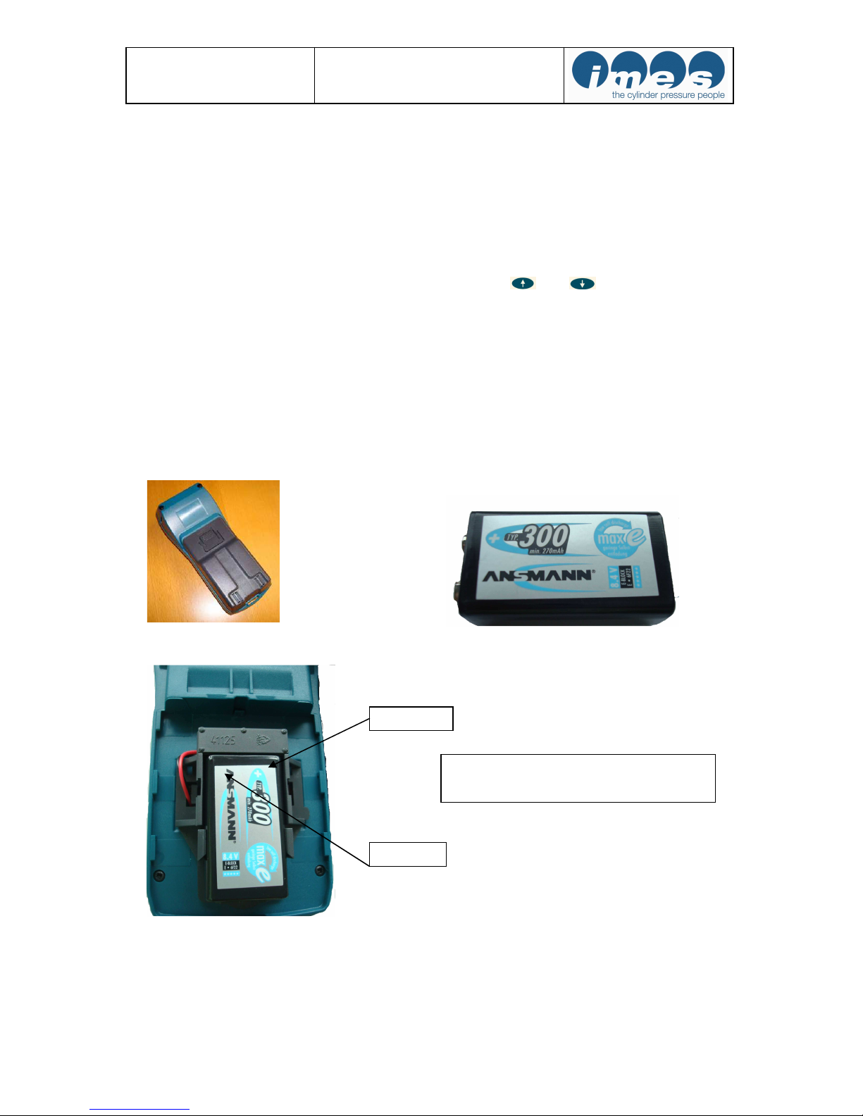
5.5 Change battery
Note: Please only use re-chargeable battery E-block type “ANSMANN 270 mAh NiMH”
For to change re-chargeable battery the battery cover on the back side of EPM-XP must be opened (fig.
10,11,12). Do not change battery during charging process while EPM-XP is connect via USB cable to PC.
Fig.10: Battery cover Fig.11: Re-chargeable E-block battery type: Ansmann
Fig.12: Battery installed on back side of EPM-XP
Note: If battery of standard NiMh 270 mAh type Ansmann can not be charged or is not available than operator
can use for measurements Alkaline battery 9V only for a short time. In this case please disconnect EPM-XP
unit after transferring data to PC !
+ Pol
The battery should only be installed by
correct pole of battery !
-
Pole

Operation manual EPM-XP
Software Release l.0.5.17 2019-01-29
Page 13 of 50
5.6 Mounting instructions on 2-stroke engines
Measuring at the indicator valve
• Before mounting the adapter, please clean the indicator valve by opening (1-2s).
To avoid measurement distortion:
• Check adaptor and sensor periodically for dirtiness and clean it if necessary.
Fig. 13: EPM-XP with HTT sensor mounted on adaptor at the indicator valve
Note: It is not allowed to use a hammer or equivalent tool to open or close the adaptor.
The user must use spanner tool on pins for to close or open adaptor on indicator cock!
5.7 Measurements with EPM-XP
• Charge battery
Charging time: min. 1 hour
• Start measurements on the engine
2-and 4 stroke application
Open and close indicator cock. Install sensor with adaptor on cylinder no.1 and open indicator cock
Press “On” at EPM-XP
Press “2/4” for load selection on 2-stroke engines
Fig.14: Indication of load (Steps: Load undefined, 25 %-, 50%-, 75%-,85%-, 90%-, 100%-, 110% load)
Press “Measure” and wait about 5-10 s
Fig.15: Indication during measurement on cylinder Fig.16: Indication (1-2 s) of measured values
After indication of measured cylinder values (1-2s) the display switches automatically to next cylinder.
Repeat measuring procedure for all remaining cylinders!
For to change engine mode 2- or 4-stroke press “2/4” to select application on a 2- or 4 stroke engine
Remark: The EPM-XP has an overheating protection of measuring cell for temperature > 300 °C
Remark: The EPM-XP turns off automatically after 2 minutes without pressing any push button!
DANGER!
The indicator valve ejects hot gas under high pressure. Danger of sparks and burning.
Hot gases and particles may be ejected.
War gloves and safety glasses!
It must be tighten the sensor and adapter connection part firmly before measuring
operation for safety of worker. Please see also chapter 10.
Operation manual EPM-XP
Software Release l.0.5.17 2019-01-29
Page 14 of 50
6 Visualisation software release 1.0.5.17
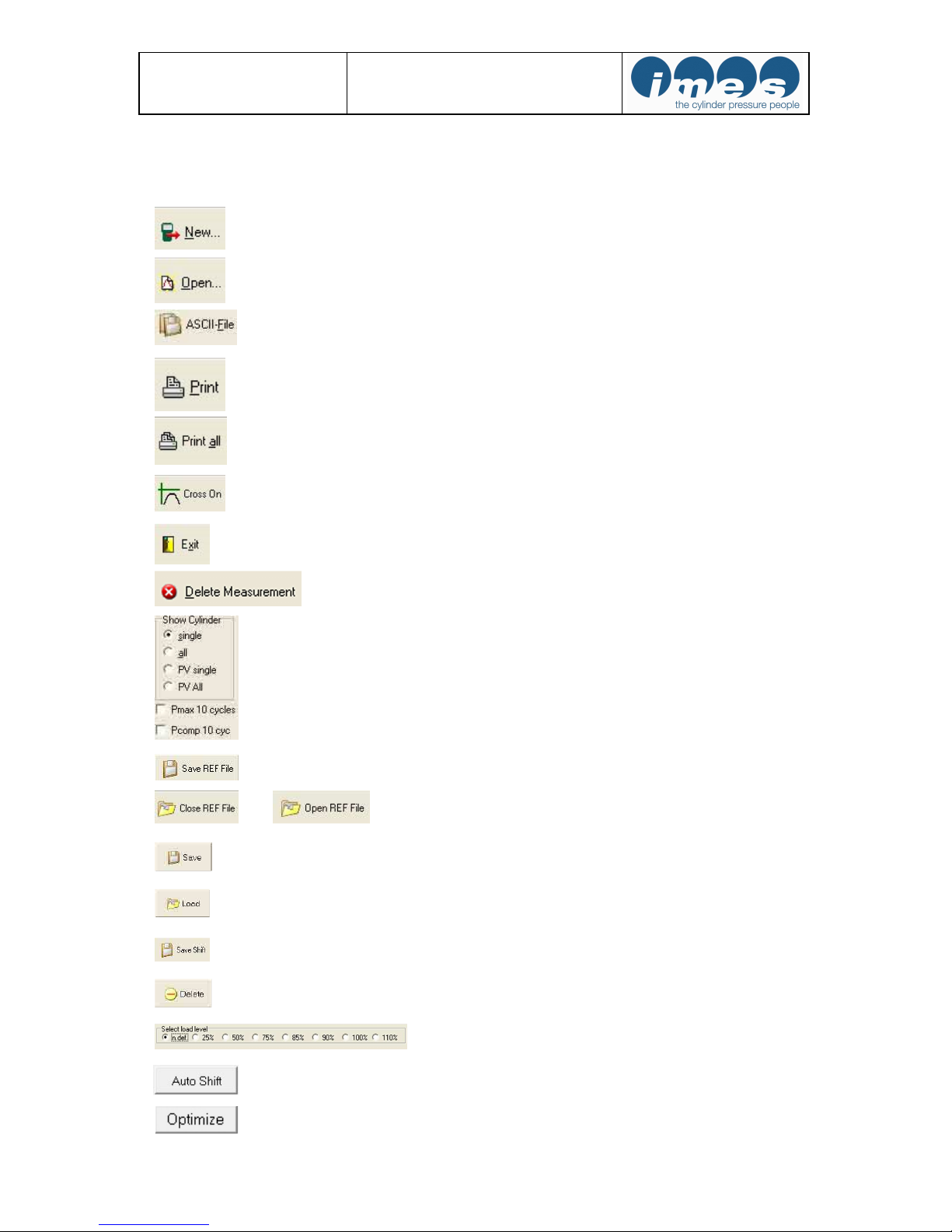
6.1 Main tool bar buttons
Load new measurement data from EPM-XP
Open stored measurement data set
Save data as ASCII file (*.csv) from all measurements
Print screen page
Print all sceeen pages
Cross On function
Program exit
Delete measurements at EPM-XP
Selection window of cylinder
p/alpha, p/v diagram
Indication Pmax 10 cycles
Indication of Pcomp 10 cycles (only on two strokes)
Save a reference file
Close and open reference file
Save Engine data
Load Engine data
Save shifted values
Delete Engine data
Load selection
Automatic shift of cylinder curve to reference curve
Funktion for to optimize Pcomp position
Only on two-stroke application available
Operation manual EPM-XP
Software Release l.0.5.17 2019-01-29
Page 15 of 50
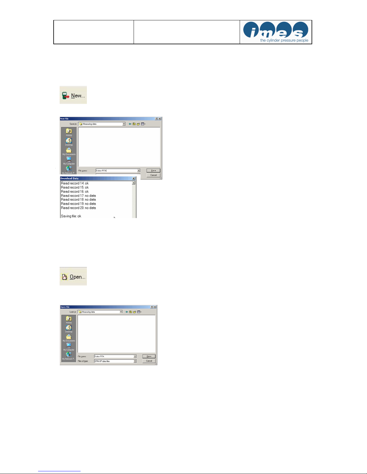
6.2 Load measured data from EPM-XP to PC
Visualization software must be started.
EPM-XP must be connected via USB cable to PC
Press “New” to load measurement data from EPM-XP to PC
The software opens a window to name the file for storing on PC
After entering a file name and storing the data will be transmitted to PC.
After this procedure the measured data will be monitored at visualisation software.
6.3 Load measured data from hard disc to PC
At first the visualization software must be started.
Press “Open” to load measurement data from EPM-XP to PC.
The software opened a window for to open a stored file on PC.
After this procedure the selected data file will be monitored at visualisation software.
 Loading...