

IMER USA MASONRY 350 F 1188792, MASONRY 350F Manual Instruction

U.S.A. inc.
MASONRY 350F Sawing machine
R
MANUAL INSTRUCTION
and
PARTS LIST
Model - 1188792
Machine serial N°
Manual Part. number 3210296 - 05/2002
Write in the serial n° of your machine here
2
MASONRY 350 F
IMER INTERNATIONAL S.p.A.
Thank-you for purchasing a Masonry 350F from an Imer U.S.A. dealer. Your decision is an intelligent one.
There is no other sawing machine in the world which delivers the benefits and features of the Masonry 350F:
- Extremely rigid, mig welded bar steel frame.
- 5.5 H.P. Honda engine.
.
- Compact design for easy trasportation.
- Extremely rigid worktable for a precise cutting.
At IMER U.S.A. we continually search for ways to better serve our customers. Should you have an idea or thought to
share with us regarding this product we would appreciate hearing from you. Our motto is "Tools and Services for the
21st Century" . We look forward to delivering the goods.
Thank you again for your purchase.
Mace T. Coleman, Jr.
President, Imer U.S.A, Inc.
IMER WEST
207 Lawrence Avenue
So. San Francisco, CA 94080
Tel 650 - 872 - 2200
Fax 650 - 873 - 6482
IMER EAST
221 Westhampton Place
Capitol Heights, MD 20743
Tel 301 - 336 - 3700
Fax 301 - 336 - 6681
1
2
3
4
5
6
7
8
9
10
11
12
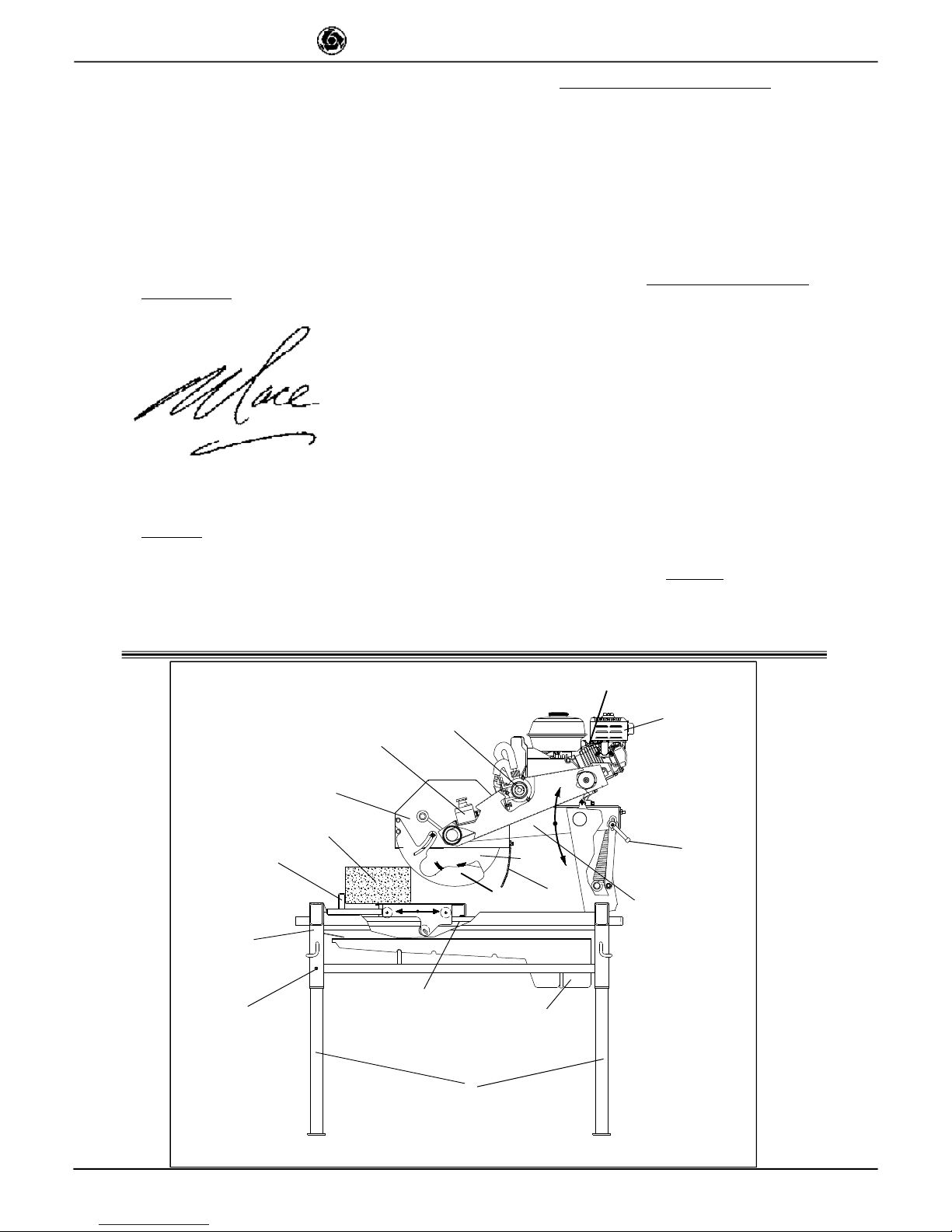
Fig. 1
13
14
15
16
17
1. Telescopic leg
2. Spray guard
3. Engine
4. Blade support
5. Water pump
6. Guide
7. Emergency switch
8. Worktable
9. Water tank
10. Blade cover
11. Support locking handle
12. Work piece
13. Blade
14. Frame
15. Earth screw
16. Blade guard
17. Accelerator lever
3
MASONRY 350 F
IMER INTERNATIONAL S.p.A.
Dear Customer,
Congratulations on your choice of purchase: this IMER saw, the
result of years of experience, is a fully reliable machine and is
equipped with the latest technical innovations.
- WORKING IN SAFETY
Please read this manual before beginning to assemble or
operate this piece of equipment.
- This OPERATION AND MAINTENANCE manual must be kept on site
by the person in charge, e.g. the SITE FOREMAN, and must always
be available for consultation.
- This manual is to be considered an integral part of the machine, and it
must be preserved for future reference (EN292/2) throughout the
machine’s normal working life. If the manual is damaged or lost, a
replacement may be requested from the saw manufacturer.
- The manual contains important information regarding site
preparation, installation, machine use, maintenance procedures
and requests for spare parts. Nevertheless, the installer and the
operator must both have adequate experience and knowledge
of the machine prior to use.
- To guarantee complete safety of the operator, safe operation
and long life of equipment, follow the instructions in this manual
carefully, and observe all safety standards currently in force for
the prevention of accidents at work. Use personal protection
(safety footwear, suitable clothing, gloves, goggles, etc.).
- Safety glasses or a protective visor must be worn at all
times.
- Ear protection must be worn at all times.
- MAKE SURE THAT WARNING SIGNS ARE ALWAYS
LEGIBLE.
- It is strictly forbidden to carry out any form of
modification to the steel structure or working parts of the
machine.
- IMER INTERNATIONAL declines all responsibility for non-compliance
with laws and standards governing the use of this equipment, in
particular; improper use, defective power supply, lack of
maintenance, unauthorised modifications, and partial or total failure
to observe the instructions contained in this manual.
IMER INTERNATIONAL is entitled to modify the characteristics of the
sawing machine and/or the contents of this manual without
necessarily updating previous machines and/or manuals.
1. TECHNICAL DATA
Table 1 shows the saw’s technical data, referring to figure 1.
2. DESIGN STANDARDS
MASONRY 350 F saws are designed and manufactured according
to the following standards: EN 292-1-2; EN 12418.
3. NOISE EMISSION LEVEL
Table 2 indicates the environmental noise levels measured for the panel
saw (lwa) in accordance with EN ISO 3744 and the acoustic pressure
level measured at the operator’s ear with the machine empty (Lpa).
TABLE 2 - [ dB(A)]
SAWING MACHINE TYPE OF MOTOR
L
P
A
L
WA
Masonry 350F ENG HONDA GX 160 K1( Hp 5.5) 95 107
4. CUTTING SPECIFICATIONS
This saw model has been specially designed for cutting stone,
ceramics, marble, granite, concrete and similar materials. Only watercooled diamond blades with continuous or segmented edges (see
paragraph 13) must be used. Under no circumstances must dry
cutting blades be used or materials other than those specified above.
IMER INTERNATIONAL declines all responsibility for damage caused
by improper use of the above machine.
5. CUTTING CAPACITY
- max. cutting capacity with vertical blade = 5 " in. one single pass.
- max. height of workpiece: 9" in. in two passes.
- min. width of workpiece: 2" in.
- max. cutting length: 18" in. (with blade lowered), 21" in (with blade
fully raised).
-Blade at 45°: with support at 45° on the work surface.
6. WARNING
- Do not load the saw with workpieces that exceed the specified
weight (max. 90 lb.)
- Ensure stability of machine: it must be installed on a solid base with
a maximum slope of 5° (fig. 2).
- Ensure the workpiece is stable before, during and after cutting: in
any case, workpieces must not overhang the worktable.
- Respect the environment; use suitable receptacles for collection of
cooling water contaminated with cutting dust.
7. SAFETY PRECAUTIONS
- IMER saws are designed for work on construction sites and under
conditions of natural light, hence the workplace must be adequately lit.
- The machine must never be used in environments subject
to risks of explosion and/or underground sites
- IMER saws may only be used when fitted with all
required safety devices, which must be in perfect
condition.
- The symbol shown on the label (fig. 3) indicates the
warning “ENSURE ALL PROTECTION DEVICES ARE
INSTALLED AND IN PERFECT CONDITION BEFORE
SWITCHING ON THE MACHINE”.
8. TRANSPORTATION (fig.4)
- WARNING Lock blade support arm by means of the
relative handle before moving the saw (ref. 11, fig. 1). To
transport the machine use slinging equipment with 4 rope
legs, fixing the hooks to the relative attachments (fig. 4).
9. INSTALLATION (fig. 4)
- Lift the machine out of its package using slinging equipment with 4
rope legs. Fix the hooks to the relative attachments.
- Unlock the legs by sliding out the split pins (ref.1).
- Lock the legs at working height. Refit the pins in the leg supports and
insert the split pins.
- Install the machine on a completely even and stable surface.
- Release the carriage from the lever that secures it to the frame.
– Fill the pump with water, unscrewing the connector (fig.10).
When installing on site it is good practice to connect the machine’s
metal structure to the earthing system by means of the screw
(fig.1 ref.15) using an earthing braid (or cable) with a minimum
cross-section of 16 mm2.
10. STARTING THE MACHINE.
The endothermic motor is equipped with a centrifugal clutch which
engages automatically, transmitting drive to the cutting wheel as the
engine revs up.
The hazard warnings and the instructions for use and maintenance
contained in the manual enclosed with the endothermic engine must
be read and understood before the engine is started.
1-Check the engine (see enclosed engine manual).
2-Check the oil level in the motor; horizontal motor position (see
enclosed motor manual).
3-Fill the fuel tank (enclosed engine manual).
4-Set the accelerator lever to minimum, so as to start the motor
without turning the cutting wheel (clutch not engaged).
5-Warm the engine by letting it run at low speed
- Emergency-stop: press the engine stop button (ref. 7,
fig. 1), (turn to switch on again).
Keep far enough away from the saw when it is running to avoid
inhaling exhaust gases from the endothermic engine.
Fig. 3
TABLE 1 - TECHNICAL DATA
Blade rpm rpm 2.450
Blade diameter in. 14"
Blade mounting hole in. 1"
Engine type Honda GX 160
Power engine Hp 5.5 / 3.600 rpm
Motor rpm rpm 3.400
Cutting table dimension in. 20" x 17"
Overall dimensions
(widthxlengthxheight)
in. 34" x 47" x 58"
Overall dimensions for
transport
(widthxlengthxheight)
in. 33" x 50" x 46"
Weight lb. 250
Weight for transport lb. 300
Blade rotation direction(seen
from blade clamping flange)
CLOCK WISE
 Loading...