

Page 1

OPERATING, MAINTENANCE, SPARE PARTS MANUAL
09/2003 - R5
- Cod. 3214816 -
IMER U.S.A. Inc.
207, Lawrence Avenue
South San Francisco, California 94080
(650) 872-2200
COMBI 350
SAWING MACHINE
Page 2
2
IMER U.S.A. Inc.
COMBI 350
Dear Customer,
Congratulations on your choice of purchase: IMER saws are the result of
years of experience and is equipped with all the latest technical innovations.
WORKING IN SAFETY
To work in complete safety, read the following instructions carefully.
- This OPERATION AND MAINTENANCE manual must be kept on site
by the person in charge, e.g. the SITE FOREMAN, and must always be
available for consultation.
- The manual is to be considered integral part of the machine and must
be kept for future reference (EN 292/2) until the machine is disposed of.
If the manual is damaged or lost, a replacement may be requested from
the saw manufacturer.
- The manual contains important information regarding site preparation,
machine use, maintenance procedures, and requests for spare parts.
Nevertheless, the installer and the operator must both have adequate
experience and knowledge of the machine prior to use.
- To guarantee complete safety of the operator, safe operation and long
life of equipment, follow the instructions in this manual carefully, and
observe all safety standards currently in force for the prevention of accidents
at work (use of safety footwear and gloves in accordance with S.I. N°3073
of 30/11/92).
Pay special attention to warnings bearing the following symbol.
Safety glasses or a protective visor must be worn at all
times.
MAKE SURE THAT SIGNS ARE LEGIBLE.
It is strictly forbidden to carry out any form of modification
to the steel structure or working parts of the machine.
- IMER INTERNATIONAL declines all responsibility for non-compliance
with laws and standards governing the use of this equipment, in particular;
improper use, defective power supply, lack of maintenance, unauthorised
modifications, and partial or total failure to observe the instructions contained
in this manual.
2. DESIGN STANDARDS
COMBI 350 saws are designed and manufactured according to the
following standards: I.E.C. 34.4; EN 89/392 (91/368/CEE); CEI EN 60204.
3. NOISE EMISSION LEVEL
Operator exposure to sound emission levels (continuous sound pressure
levels equal to A weighting); the COMBI 350 saw noise emission level
during cutting is 93 dB(A) with continuous rim blade.
4. CUTTING SPECIFICATIONS
This saw model has been specially designed by IMER for cutting stone,
ceramics, marble, granite, concrete and similar materials. Only water-
cooled diamond blades with continuous or segmented edges must be
used. Under no circumstances must dry cutting blades be used or
materials other than those specified above. IMER INTERNATIONAL
declines all responsibility for damage caused by improper use of the
above machine.
TECHNICAL DATA
COMBI 350
350/600 350/1000
Blade rpm
rpm 2150 2040 / 2150
Blade diameter
inc 14''
Blade mounting hole
inc 1''
Motor rating
Hp 3.0 1.5 / 3.0
Motor rpm
rpm 3450 3260 / 3450
Cutting table
dimensions
inc 20'' x 31'' 20'' x 46''
Overall dimensions
inc 47'' x 34'' x 51'' 63'' x 34'' x 51''
Overall dimensions for
transport
inc 51'' x 28'' x 37'' 67''x 31'' x 37''
Weight
lb 253 287
Weight for transport
lb 298 342
Blade rotation
direction(seen from
blade clamping flange)
ANTI - CLOCKWISE
Current
A 11 13.4 / 11
Voltage
V 230 115 / 230
Frequency
Hz 60
5. CUTTING CAPACITY
- Max. thickness (inc): 5'' (90°); 3'' (45°)
- Workpiece width (inc): max. 20'' ; min 2''
- Length: COMBI 350/600 COMBI 350/1000
thk. x l (inc) 1'' x 24'' 1'' x 40''
3'' x 22'' 3'' x 38''
(*) 90° cut from above
5'' x 21'' 5'' x 37''
5'' x 28'' (*) 5'' x 43'' (*)
(**) 45° 45 x 21'' (**) 70 x 37'' (**)
6. WARNING
- Do not load the saw with workpieces that exceed the specified weight
(max. 90 lb).
- Ensure stability of machine and workpiece before, during or after cutting.
Install supplementary support surfaces at the same height as the
worktable.
- Respect the environment; use suitable receptacles for collection of
cooling water contaminated with cutting dust.
7. SAFETY PRECAUTIONS
IMER saws are designed for work on construction sites and under
conditions of natural light and in workshops under conditions of natural
or artificial lighting of minimum 500 LUX.
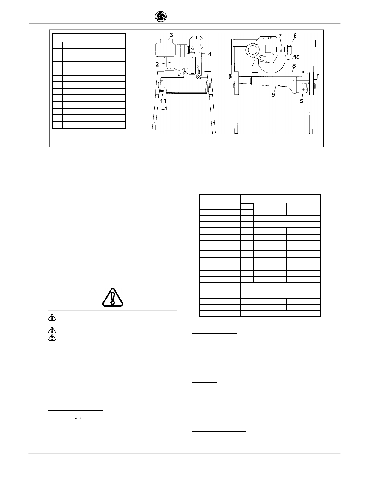
Fig. 1 MACHINE LAY-OUT
1 TELESCOPIC LEG
2 SPRAY GUARD
3 MOTOR
4
BLADE SUPPORT
ARM
5 WATER PUMP
6 GUIDE
7 MAIN SWITCH
8 WORKTABLE
9 WATER TANK
10 BLADE GUARD
11 EARTHING SCREW
12 HEAD BLOCKAGE
Fig. 1 - Machine Lay-out
Page 3
3
IMER U.S.A. Inc.
COMBI 350
The machine must never be used in environments
subject to risks of explosion and/or underground sites.
- IMER saws may only be used when fitted with all required safety devices
which must be in perfect condition.
- Never use makeshift and/or faulty power cables.
- Make electrical connections on the construction site where they will
not be subject to damage. Never stand the saw on power supply cables.
- Lay power cables where they are not subject to risk of damage or
contact of connectors with water. Only use connectors fitted with waterspray protection (IP55).
- Repairs to electrical installations must only be carried out by qualified
technicians. Always ensure that the machine is disconnected from the
power supply and is completely immobile during repairs and maintenance
operations.
- Connect the machine to a suitable equipotential earthing
plant on the construction site with wire braid of minimum
16 mm² section. The connection point is identified by a
screw welded to the frame (see Fig.1), and on the rating
plate by the
earthing symbol.
- Stop the saw only by means of the main switch.
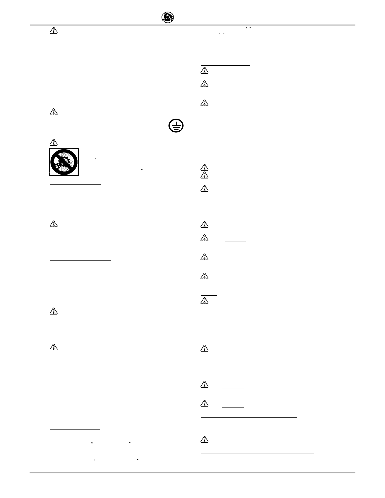
- The symbol shown on the label (see left) indicates the
warning ENSURE ALL PROTECTION DEVICES ARE
INSTALLED AND IN PERFECT CONDITION BEFORE
SWITCHING ON THE MACHINE
8. ELECTRICAL SAFETY
IMER saws comply with EN 60204-1; and are fitted with:
- protection device against automatic re-start after power failure;
- Short-circuit cutout device;
- Motor overload cutout switch.
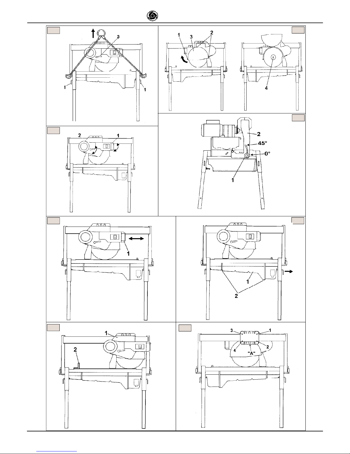
9. TRANSPORTATION (Ref. Fig.2)
WARNING! Always remove the plug from the power socket
before moving the saw, and lock head support carriage movement
by means of the relative knob (ref. 3). To transport the machine use
slinging equipment with 4 rope legs, fixing the hooks to the relative
attachments.
10. INSTALLATION (Ref. Fig.2)
Fix the hooks to the relative attachments on the machine and lift the
machine out of its package.
- Unlock the legs by sliding out split pins (ref.2) and pins (ref.1).
- Lock the legs at working height. Refit the pins in the leg supports and
insert the split pins.
- Install the machine on a completely even and stable surface.
11. ELECTRICAL CONNECTION
Ensure that there is an overload cutout device fitted up-
line on the power line. If necessary, install an IMER quick connect
residual current circuit breaker (RCCB) (code no. 1169245 available
in kit form for 230V machines).
Ensure that the mains voltage corresponds to that specified for the
machine: 230V/60Hz - 115V/60Hz.
All power supply installations must comply with CEI 64-
8 standards (harmonised document CENELEC HD384).
The electrical power cable must be suitably sized to avoid voltage drops.
Cable drums (with collector rings) must not be used.
Cable dimensions will vary according to the start-up current and length of
cable. In general cable sizes of 4 mm² are sufficient for lengths up to 160
ft. After installation always carry out voltage testing under load conditions,
both at start-up and during operation. During operation, voltage drops
must never exceed 5%. In the case of longer cables or a power supply
network subject to variations, use cables with a section of at least 6
mm². Cables used on construction sites must be fitted with suitable
external sheathing that is resistant to wear, crushing and extreme weather
conditions.
12. MACHINE START-UP
Before connecting the machine to the power supply:
1 - Ensure that the metal structure is connected to an earthing plant as
indicated in Section 7 Safety Precautions .
2 - Ensure that the tank contains sufficient cooling water.
3 - Ensure that the power circuit corresponds to the requirements as
indicated in Section 11 Electrical connections
4 - Connect the machine to the power supply.
5 - Set the switch to 1 and when the motor is started return to
position 0 after ensuring that cooling water reaches the blade.
6 - Check that the direction of blade rotation corresponds to that
indicated by the arrow on the blade guard.
7 - If all is in order, proceed with cutting.
13. EMERGENCY STOP
- In the event of emergency,stop the machine by pressing
the stop control switch.
- The motor is fitted with an overload cutout device. If the
motor overheats, it will automatically shut down. Allow motor to
cool before re-starting.
- The motor is protected against automatic re-start after
interruptions due to power failure. To resume operation, when power
is re-connected, repeat machine start-up procedure.
14. BLADE INSTALLATION (Ref.Fig.3)
By means of a hex wrench no.10, remove front screws (ref.1) and loosen
the other two screws (ref.2) which secure the blade guard. Turn the guard
clockwise to gain access to the securing screw (ref.4). Use a hex wrench
no. 13 to remove the screw (turn anti-clockwise). Remove the mobile
flange and check that the flanges, disc shaft and blade are not damaged.
- Never use worn blades.
- Only use blades that are designed for the number of
revolutions indicated on the machine rating plate.
- Check that blade rotation corresponds to that indicated
on the blade guard.
Centre the blade against the fixed flange, position the mobile flange and
tighten the securing screw by means of a hex wrench no. 13 (turn
clockwise). Return the guard to its original position and lock by means of
screws (ref.1 and 2).
- Ensure that the blade guard is locked securely into
position.
- WARNING! An incorrectly installed blade, or a screw
insufficiently tightened can provoke damage to the machine or injury
to persons.
- Note that the blade must have an external diameter of
350 mm., a central hole diameter of 25.4 mm and max. thickness of
3 mm.
- Check that the blade to be used is suitable for the
material to be cut.
15. USE
Leave a space of 5 ft around the machine to operate in
full safety.
- Do not allow other persons to approach the machine during cutting.
- Never use the machine in fire-risk areas. Sparks can cause fire or
explosions.
- Make sure that the machine is switched off before positioning or handling.
- Always ensure that the blade is free of any contact before start-up.
- Ensure correct installation of all protective devices.
- Ensure that blade rotation corresponds to the indications
on the blade guard.
Before starting work, fill the water tank. Top up during operation whenever
necessary: N.B. the pump suction hose must always remain
immersed in water.
Insert the plug in the power socket.
WARNING!
For safety purposes the removal of protective
guards from the machine is strictly prohibited !
The machine is protected against overload.
WARNING!
Always switch off the machine before carrying
out blade adjustment.
15.1 VERTICAL BLADE MOVEMENT (Ref. Fig. 4)
To raise or lower the blade, slacken knob (ref.2) by turning it anti-clockwise.
Set blade support (ref.1) to the required position and lock by tightening
the knob fully (ref.2).
Ensure that the locking knob is tightened fully before
starting work.
15.2 BLADE POSITIONING FOR 45° CUTS (Ref.Fig.5)
Slacken knob (ref.1); the blade support arm (ref.2) is unlocked and
so can be set to its limit position, i.e. inclined at 45° with respect to
Page 4
4
IMER U.S.A. Inc.
COMBI 350
the worktable. Tighten the knob fully to lock into position.
To bring the blade back to the vertical position (pos.0) carry out the above
operations in reverse order.
Ensure that the locking knob (ref.1) is tightened fully before
starting work.
15.3 CUTTING
- Before cutting, check that the blade is aligned with the cutting
line.
- Place the workpiece on the worktable snugly against the fence.
- Start the motor and wait until the water reaches the blade to
begin cutting.
- Start cutting movement by pulling the carriage towards you
by means of the relative handle (ref.1 fig.6).
As cutting thickness increases, the blade is subjected to
greater stress. To avoid overloading the motor, the operator should
continually check blade feed speed. The speed will also depend on
the characteristics of the material being cut (hardness, toughness
etc.).
15.3.1 CUTS WITH BLADE LOWERED FROM ABOVE
(Ref. Fig.8)
Bring the blade support to its highest position and lock. Position the
workpiece on the worktable. Start the machine, unlock the blade support
and begin vertical cutting until the blade reaches its lowest point. Lock
the support once more and proceed with horizontal cutting.
15.3.2 BLADE CHANGE
To change the blade refer to section 14. BLADE INSTALLATION.
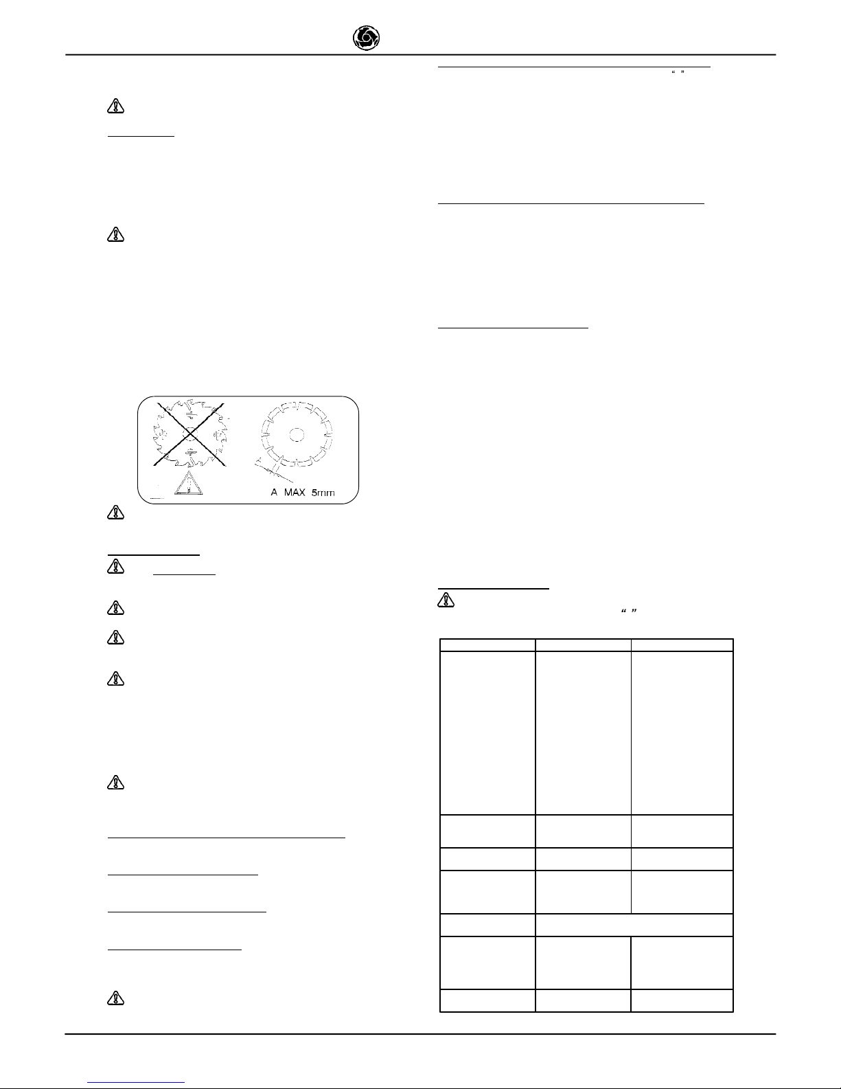
Do not use blades for wood or segmented disks with
slots wider than 5 mm.
16. MAINTENANCE
- WARNING!
Always switch the machine off and
remove the plug from the power socket before carrying out
any maintenance operations .
- Always check that the protective guards are in the
correct position and in perfect condition.
- As there is the continuous risk of inadvertent damage
to the electric cables, these must be checked regularly each
time before the machine is used.
-WARNING! If the electric motor or control panel
are removed for maintenance, it's necessary to replace
the relevant seals in order to guaranty the right degree
of protection and safety against water penetration inside
to the electric circuits.
Never leave the machine out in the open. Make sure that it is stored
in a sheltered area away from extreme weather conditions.
Replace worn or faulty components with original spare parts.
- WARNING! Recommend product for cleaning
and lubrificating the mechanical parts of the saw:
WD-40
16.1 TANK CLEANING ON WORK COMPLETION
On completion of work, empty the tank and remove. Clean
thoroughly to remove cutting residue.
16.2 TANK REMOVAL (Ref.Fig.7)
Lift the tank (ref.1) to detach from its supports (ref.2) and remove
from the side indicated by the arrow.
16.3 WORK SURFACE CLEANING
Always keep work surfaces clean. Residual dirt can impair cutting
precision.
16.4 GUIDE RAIL CLEANING
The horizontal guide elements on the carriage are protected against
dirt build-up by scrapers. However we advise thorough cleaning of
the guide rails to ensure correct operation.
WARNING! Do not use any type of lubricant on the
guide rail.
FAULT CAUSE REMEDY
Motor does not start
when switch is
turned
- Defective power
cable
- Plug not inserted in
socket correctly
- Power cable from
plug to control panel
detached
- Loose wire inside
motor circuit board
- A wire has become
disconnected inside
the panel
- Faulty main switch
-The overload safety
device has been
activated.
- Check power cables
- Ensure correct
connection
- Connect cable- re
-Connect wire
- Remake the connection
- Replace switch
-Wait for a few minutes
and then try restarting
the machine.
Vertical blade
movement not
smooth
- locking knob too tight - Slacken knob
Blade inclination not
smooth
- locking knob too tight - Slacken knob
Horizontal carriage
movement not
smooth
- Locking knob too
tight.
-Incorrect guide wheel
adjustment .
- Slacken knob
- Adjust (Chapter 16.8)
Lack of cooling water
supply to blade
Refer to section: "cleaning and maintenance of
cooling circuit"
Blade does not cut
- Incorrect blade
rotation
- Blade is worn
- Remove the blade and
refit in the position as
indicated on the blade
label.
- Fit new blade
Motor starts but
blade does not rotate
Belt is broken Replace drive belt, see
Chapter 16.6
16.5 CARRIAGE CLEARANCE ADJUSTMENT (Ref. fig.9)
LATERAL ADJUSTMENT: turn adjustment screw 1 gradually
clockwise using a hex wrench no.3, so that the internal roller
comes into contact with the bar. Take care not to exert too much
pressure. Repeat the same operation with the other adjustment
screws according to the order indicated in the figure. Adjust
vertical clearance by means of the screws located on the lower
part of carriage (A). On completion, if carriage travel is not smooth,
slacken the adjustment screws by turning the wrench anticlockwise; if clearance has not been eliminated repeat the above
operation.
16.6 CLEANING AND MAINTENANCE OF COOLING CIRCUIT
- If water does not reach the blade stop the machine immediately to avoid
blade damage.
- After switching off the machine ensure that the water level is sufficient.
- If necessary, after disconnecting the machine from the power supply
check that the tap, hose and pump filter are not blocked
- If necessary, check that the impeller rotates freely (after extended periods
of disuse)
- If necessary, remove the pump and check that the pump/motor coupling
is in perfect condition.
16.7 DRIVE BELT REPLACEMENT
- Disconnect the machine from the power supply
- Remove the water hose connection by loosening the hose clamp on the
blade guard.
- Remove the blade, the two flanges, the blade half-guard securing screws,
the locking knob (ref.1, chart 02) and remove the blade external halfguard (motor side).
- Remove the blade shaft with pulley from the bearing (ref.27, drawing 02)
and fit into the bearing of the half-guard previously removed (ref.14, chart
02).
- Fit the new belt onto the two pulleys and refit the belt tensioner.
- Refit the seal on the edge of the guard and ensure that it is in good
condition and that the two locating pins are in the correct position.
- Refit the guard inserting the blade shaft into the bearing (ref.27, chart
02) taking care to align the screw (ref.51, drawing 02) located on the slot
of the head fulcrum (ref.19, drawing 02) with the locking handle hole
(ref.1, drawing 02).
- Join the two blade half-guards using the two locating pins to align correctly.
- Screw in the two blade half-guards by tightening diagonally opposite
screws alternately.
- Screw in and tighten the locking handle before installing the blade.
17. TROUBLESHOOTING
N.B.: Before carrying out any maintenance operations,
switch off the machine, set the switch to 0 and remove the plug
from the power socket.
Page 5
5
IMER U.S.A. Inc.
COMBI 350
Fig.8
Fig.6
Fig.4
Fig.2
Fig.7
Fig.5
Fig.3
Fig.9
Page 6
6
IMER U.S.A. Inc.
COMBI 350
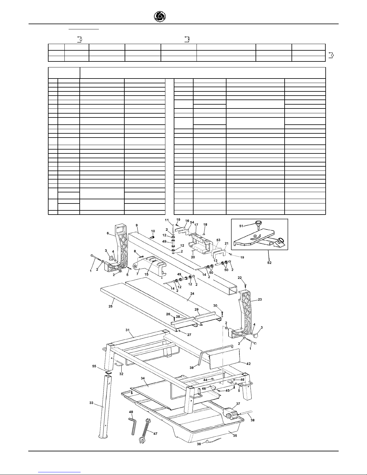
18. SPARE PARTS
:All orders for spare parts must indicate the following: 1 - Type of machine.2 - Part number and position number of each part.3 - Serial number and year
of manufacture reported on the machine's identification plate.
SYMBOL: Interchangeability (example):Pos..1 P.n. 3204530 was installed on machincs up to N° 5240 and Pos.1.1 P.n. 3204520 installed on machine N° 5241 onwards. Pos. 1.1 is
interchangeable ( ) with Pos. 1.Pos. 1 and Pos. 1.1 are not interchangeable if the ( ) symbol appears in the table.
Rif. Cod. I F GB D E Note
1 3204530
Riduttore Réducteur Reducer Untersetzungsgetriebe Reductor 5240
2 3204520
Riduttore Réducteur Reducer Untersetzungsgetriebe Reductor 5241
AK 0 12 - AK 013 TAB 1 - FRAM E AS S E M B LY
RIF. COD. USA D E TA ILS RIF. COD . USA DETAILS
1 3205730 BOLT 57 37 12X 1 00 27 2 223 924 NUT AUTOB L.D IAM.6
2 22 243 80 WA S HER 65 93 Ø12 X25 28 320 5470 E ND S TOP SX
3 32 047 43 HAND W H EEL 29 32 054 71 END STOP DX
4 222 434 0 WA S HER 659 2 Ø10X 20 30 2222 515 BO LT 59 31 M 8X16
5 320 569 9 BOLT 59 11 M10x6 00
31
32 14696
FR A ME
COM B I 600
6 323 2701 ROTARY B L ADE A RM DX 32 14713 COM B I 1000
7 32 327 03 C A RRIAGE DX 32 2228840 P IN
8 22 221 37 B OLT 5739 M16 x50 33 3 201517 COLLAPSIBLE L E G
9
32 327 46
32 054 57
GUIDE BAR
COM B I 600
COM B I1000
34
32 05577
WATER RUN-OFF TRAY
COM B I 600
10 2265675 DAMP E R 32 05469 COM B I 1000
11 320 550 2 PIN 35 320 4818 D R UM
12 3206209 BEAR ING 6 001 2R S 36 2 235428 PLU G
13 32065 21 SPA C ER 37
32 08737
32 09317
PUM P
23 0V-60Hz
115V-60H z
14 3232736 PIN 38 2292 365 TU BE
15 2222088 BOLT 57 37 M8X4 0 39 3 206 318 SUP P ORT
16 3205464 FRONT S C RAPER 42 3214195 SPRAY GUA RD
17 3232704 CARRIAG E S X 44 2223921 NUT A UTOBL.M 12
18 2223570 NUT 5 588 M 8 45 222 2056 B O LT 5739 M 10X 2 5
19 22220 21 BOLT 5 739 M 6X16 46 2223650 NUT 55 88 M 1 0
20 2228820 PIN 47 2 241 570 SPANN E R
21 3205 465 REA R S C RAPER 48 3205788 SPA NNE R
22 222206 1 BOLT 573 9 M 8X 2 0 49 3206 210 W HEEL
23 3232702 ROTA RY B LADE A RM 50 22 044 21 BE A RING 62 01 2RS
24
32 054 81
CUTTING TA B LE
COM B I 600 DX 51 3 206085 HA NDWHEE L
32 054 67 COM B I 1000 DX 52 3207 219 GONIOMETER
25
32 054 82
CUTTING TA B LE
COM B I 600 SX 53 320 5465 F ILZ
32 054 68 COM B I 1000 SX 54 3205 464 FILZ
26 2222545 BOLT 593 1 M 6X 3 0 55 3201 015 PL UG
Page 7
7
IMER U.S.A. Inc.
COMBI 350
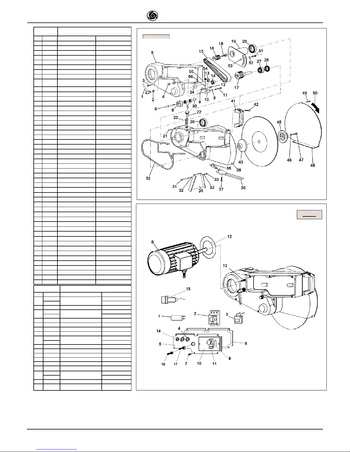
AK014 TAB. 2 MOBILE HEAD ASSEMBLY
RIF. COD. USA DETAILS
1 2284827 HANDLE
2 2224380 WASHER 6593 Ø12X25
3 2222541 BOLT 5931 M 6X25
4 2223045 NUT M10 5721-69
5 3232761 COVER
6 3214191 BOLT 5737 M10X50
7 3214655 BEARING 6000 2RS
8 3203910 ROLLER 6592 Ø10X20
9 3214198 WASHER
"SS"DIN988
10X16X1,6
10 3214193 BELT TENSIONER ARM
11 2222148 BOLT 5737 M 10X65
12 2223920 NUT AUT. M10 7474
13 3214202 SPRING
14 3206514 BEARING 6203 2RS
15 3204737 BELT
16 3204736 PULLEY
17 3206739 BLADE SHAFT-PULLEY
18 2222016 BOLT 5739 M 6X20
19 3232740 HEAD FULCRUM
19 3206488 HEAD FULCRUM
20 2204510 BEARING 6009 2RS
21 2228820 PIN 6x14
22 3204788 PIN
23 3204787 SPRING
24 3207366 COMPENSATING RING
27 2204540 BEARING 6205 2RS
28 3232759 OIL SEAL RING 35X52X7
31 2222544 BOLT 5737 M 6X60
32 2224531 WASHER 6593 Ø 6X18
33 2223924 NUT AUTOBL. M 6
34 2247898 SPRAY GUARD
35 3205635 VALVE
36 3232763 TUBE
37 2222709 BOLT 5739 M 5X10
38 3232762 SUPPORT
41 2284826 HANDLE COMBI600-MASONRY
42 2222515 BOLT 5931 M 8X16
43 3204777 INNER FLANGE
45 3204776 OUTER FLANGE
46 2224140 WASHER 6593 Ø 8X18
47 2222060 BOLT 5739 M 8X20
48 3204775 BLADE COVER
49 2222021 BOLT 5739 M6X16
50 3207128 LABEL
51 3203914 BOLT TTQ M12X80
52 3232742 GASKET
53 3206131 WASHER 3545 Ø16x35x1,4
54 3213268 SHOCK ABSORBER
55 2222537 BOLT M6X10 Z
56 2224530 WASHER 6592 Ø 6X12.5
AK 014 TA B . 3 A S S E M B LY OF M OTOR
RIF. C OD . U S A D E TA IL S
1
32 1 4262
CAPA C ITOR
115V/60H Z
22 8 5601 23 0 V /6 0HZ
2 32079 20 C ONTA C TOR
3
32 0 7927
COIL
115V/60H Z
32 0 7924 230V /60 HZ
4 32 015 0 3 CA B L E -CLA M P
5 32079 33 C OVER
6 32327 43 G A S K E T
7 32004 12 B O LT
8
32 0 7934
MOTOR
115V/60H z
32 0 7937 230V /60 Hz
9 32059 24 L A B E L
10 32 0 7929 JU NCTION B OX
11 3207 9 28 P U S H
12 32 3 2270 GA S K E T
13 122 2 252 B OLT
14 32 0 1217 CABLE-C LAMP
15
32 0 7184
PLU G
115V/60H z
32 0 8070 230V /60 Hz
16 3 206 1 71 S W ITC H C OVER
17 32 0 6170 WATER P UMP S W ITCH
TAB. 2
TAB. 3
Page 8
8
IMER U.S.A. Inc.
COMBI 350
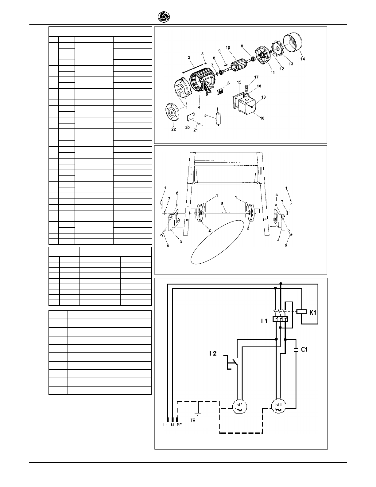
AK014 TAB. 4.1 ASSEMBLY OF MOTOR
RIF. COD. USA DETAILS
1
3203680
MOTOR FLANGE
115V/60Hz
3204830 230V/60Hz
2
2222970
BOLT
115V/60Hz
2222911 230V/60Hz
3
2223352
NUT
115V/60Hz
2223280 230V/60Hz
4
3213619
CASING AND STATOR
115V/60Hz
3216622 230V/60Hz
5
3214262
CAPACITOR
115/60 MF80 V250
2285601 230/50 MF35 V450
6 2281955 TERMINALS 115/60 230/60
7
2227900
SPLIT RING
115V/60Hz
2237340 230V/60Hz
8
2204390
BEARING
115V/60Hz: 6204 2Z
2204391 230V/60Hz: 6205 2Z
9 2229325 KEY 6X6X25 6604
10
3203681
ROTOR
115V/60Hz
3204829 230V/60HZ
11
2291495
COVER
115V/60Hz
2291494 230V/60HZ
12
2227097
OIL SEAL RING
115V/60Hz
3214031 230V/60HZ
13
2291453
MOTOR FAN
115V/60Hz
2291454 230V/60HZ
14
2291281
FAN COVER
115V/60Hz
2291282 230V/60HZ
15 2216321 GASKET
16 3213032 COVER
17 3204411 CABLE CLAMP IP68 PG16
18 3214028 SEAL RING Ø18,8X1,8 (PG16)
19 2222465 SCREW TRILOB.M5X15
20
3203262
RATING PLATE
115V/60Hz
3203980 230V/60Hz
21 2288792 RIVET
22 3203678 MOTOR FLANGE 115V/60hZ
TAB. 1 - WHEEL KIT
Rif. Cod. GB DETAILS
1 2226700 SPLIT PIN
2 2211150 WHEEL
3 3206261 LEFT TUBE GUIDE
4 3206262 RIGHT TUBE GUIDE
5 2222082 SCREW 5739 M 10X60
6 2223650 DISK 5588 M10
7 3206641 WASHER 6592 28X50X2
8 3206260 WHEEL TUBE
Fig.19 USA
L1
PHASE LINE CONDUCTOR
N
NEUTRAL LINE CONDUCTOR
PE
PROTECTION CONDUCTOR
I1
THERMO-MAGNETIC CUTOUT DEVICE
C1
MOTOR CAPACITOR
K1
COIL
M1
BLADE MOTOR
M 2
PUMP MOTOR
I 2
SWITCH
O
P
T
I
O
N
A
L
Wheel Kit (TAB. 1)
Fig. 19 - Wiring Diagram
Assembly of motor
(TAB. 4.1)
Page 9

ONE YEAR WARRANTY
We warrant to the original purchaser that the IMER equipment described herein
(the "equipment") shall be free from defects in material and workmanship under
normal use and service for which it was intended for a period of one (1) year from
the date of purchase by the original purchaser.
Our obbligation under this warranty is expressely limited to replacing or repairing,
free of charge, F.O.B. our designated service facility, such part or parts of the
equipment as our inspection shall disclose to be defective. Parts such as engines,
motors, pumps, valves, electric motors, etc. furnished by us but not manifactured
by us will carry only the warranty of the manifacturer. Transportation charges or
duties shall be borne by the purchaser. This shall be the limit of our liability with
respect to the quality of the equipment.
This warranty shall not apply to any equipment, or parts thereof, which has been
damaged by reason of accident, negligence, unreasonable use, faulty repairs, or
which has not been mantained and operated in accordance with our printed
instructions for our equipment. Further, this warranty is void if the equipment, or
any of its components, is altered or modified in any way.
THIS WARRANTY IS EXPRESSLY IN LIEU OF ALL OTHER WARRANTIES,
EXPRESSED OR IMPLIED, INCLUDING ANY IMPLIED WARRANTY OF
MERCHANTABILITY OF FITNESS FOR A PARTICULAR PURPOSE.
We make no other warranty, representation or guarantee, nor is anyone authorized
to make one on our behalf. We shall not be liable for any consequenzial damage
of any kind, including loss or damage resulting, directly or indirectly, from the use
or loss of use of the machine. Without limiting the generality of the foregoing, this
exclusion from liability embraces the purchase's expenses for downtime, damages
for which the purchaser may be liable to other persons, damages to property, and
injury or death of any persons.
This warranty shall not be deemed to cover maintenance parts, including but not
limited to blades, belts,hoses, hydraulic oil or filters, for which we shall have no
responsability or liability whatsoever.
IMER U.S.A., Inc.
207 Lawrence Avenue
South San Fancisco, California 94080
(650) 872-2200
 Loading...