

IMER MASONRY 700 Operating, Maintenance, Spare Parts Manual

MASONRY 700
SAWING MACHINE
OPERATING, MAINTENANCE, SPARE PARTS MANUAL
IMER WEST
3654, Enterprise Avenue
Hayward, CA 94545
Ph. 510.670.7970
Fax 510.783.4255
IMER EAST
221 Westhampton Place
Capitol Heights, MD 20743
Ph. 301.336.3700
Fax 301.336.6687
IMER
U.S.A. Inc.
Toll Free: 800.275.5463
www.imerusa.com
info@imerusa.com
2010/07 - R04
Cod. 3228131
IMER U.S.A. Inc.
MASONRY 700
2
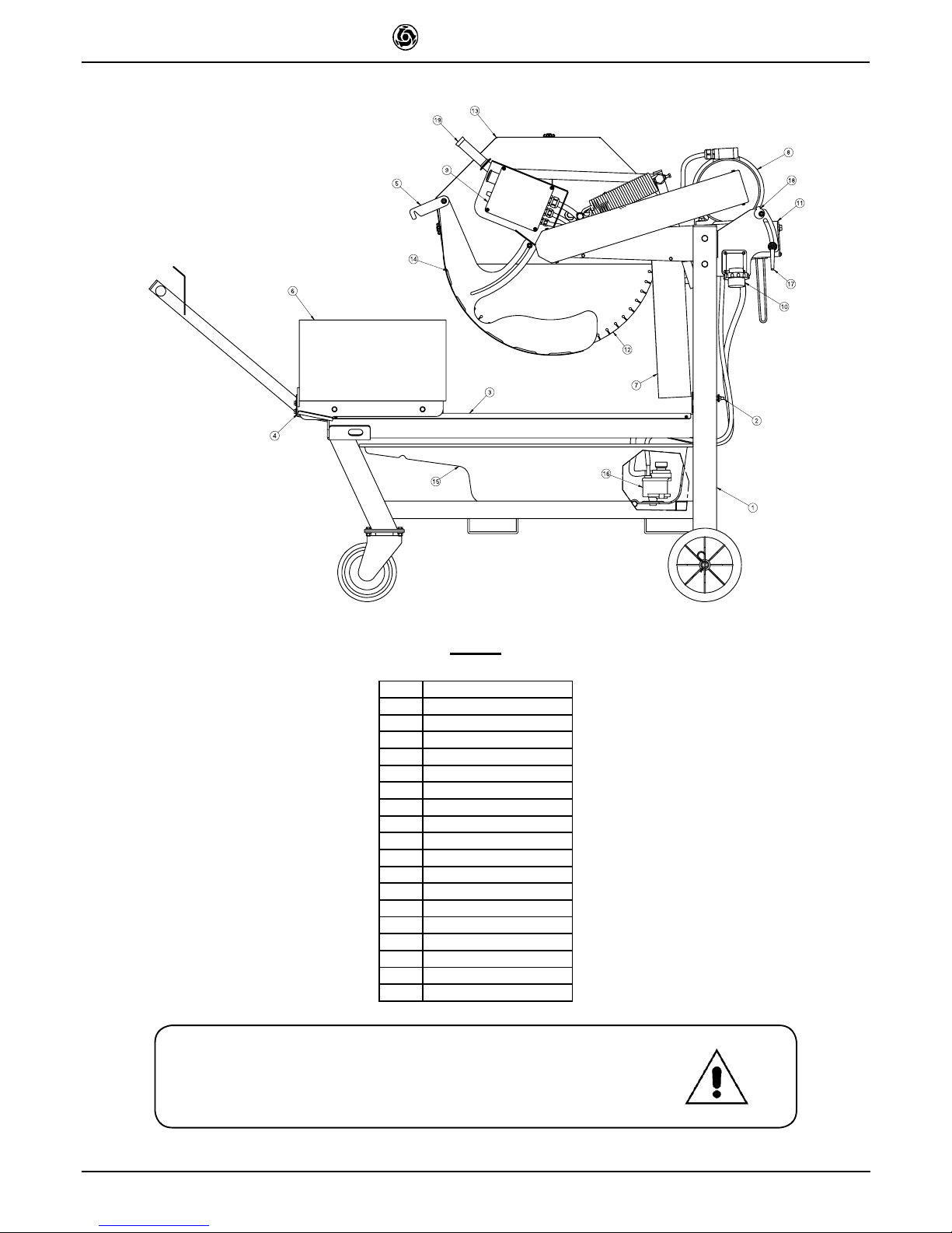
FIG. 1
REF.
DESCRIPTION
1
Frame
2
Screw
3
Guide bar
4
Carriage
5
Trolley clamping
6
Workpiece
7
Spray guard
8
Motor
9
Junction box
10
Plug
11
Cutting head group
12
Blade
13
Disc cover
14
Blade cover
15
Drum
16
Water pump
17
Adjusting cut lever
18
Cam
Special attention must be given to warnings with this symbol:
IMER U.S.A. Inc.
MASONRY 700
3
Dear Customer,
Congratulations on your choice of purchase: this IMER saw, the result of
years of experience, is a fully reliable machine and is equipped with the
latest technical innovations.
- WORKING IN SAFETY
To work in complete safety, read the following instructions carefully.
This OPERATION AND MAINTENANCE manual must be kept on site
by the person in charge, e.g. the SITE FOREMAN, and must always be
available for consultation.
This manual is to be considered an integral part of the machine, and
it must be preserved for future reference (EN 12100/2) throughout the
cement may be requested from the saw manufacturer.
The manual contains important information regarding site preparation,
installation, machine use, maintenance procedures and requests for
spare parts. Nevertheless, the installer and the operator must both have
adequate experience and knowledge of the machine prior to use.
To guarantee complete safety of the operator, safe operation and long
life of equipment, follow the instructions in this manual carefully, and
observe all safety standards currently in force for the prevention of
accidents at work. Use personal protection (safety footwear, suitable
clothing, gloves, goggles, etc.).
- The use of protective goggles is compulsory.
- Ear protection must be worn at all times.
- Make sure that warning signs are always legible.
the steel structure or working parts of the machine.
IMER INTERNATIONAL declines all responsibility for non-compliance
with laws and standards governing the use of this equipment, in particular; improper use, defective power supply, lack of maintenance,
instructions contained in this manual.
IMER INTERNATIONAL is entitled to modify the characteristics of the
sawing machine and/or the contents of this manual without necessarily
updating previous machines and/or manuals.
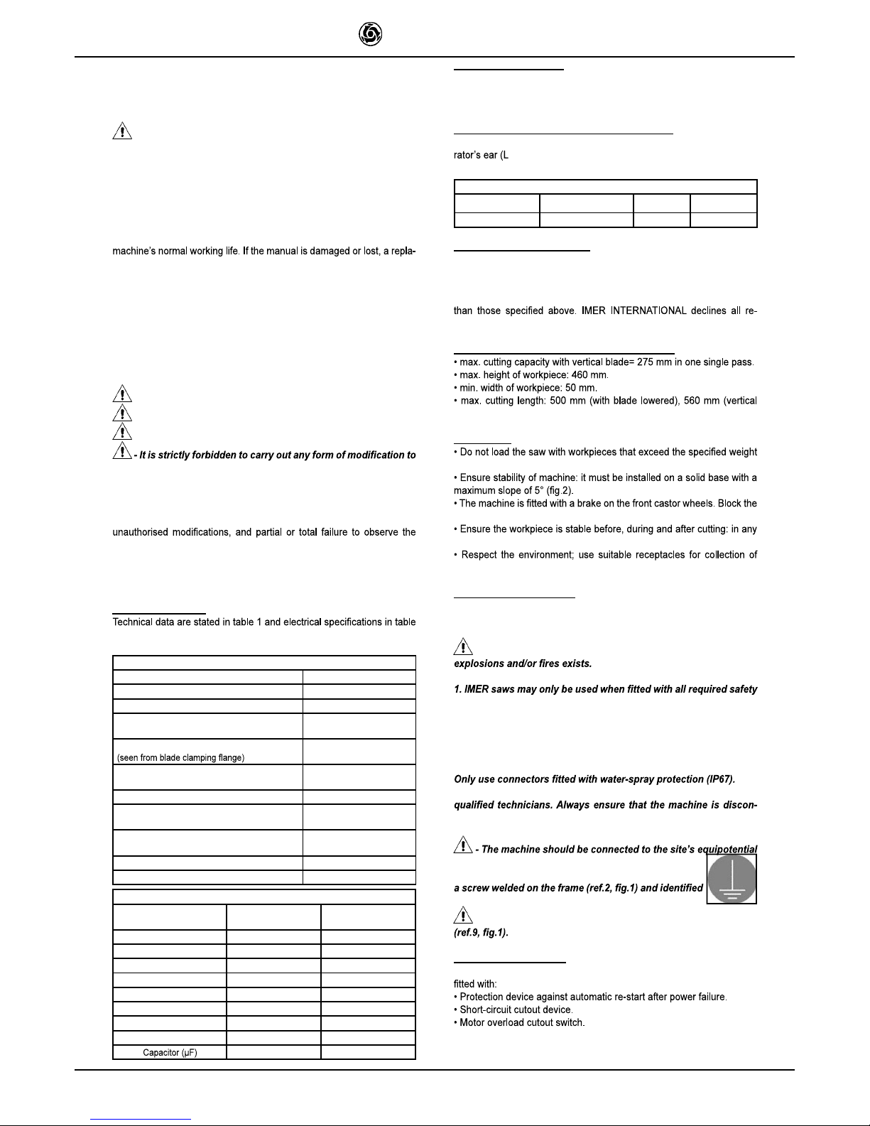
1. TECHNICAL DATA
2.
Table 1 - TECHNICAL DATA
Model
Masonry 700
Blade diameter
700 mm
Blade mounting hole
25,4 mm
Blade rpm (220V/60Hz) single-phase
Blade rpm (220V/60Hz) three-phase
1220 rpm
1710 rpm
Blade rotation direction
clockwise
Motor rating 220V/60Hz single-phase
Motor rating 220V/60Hz three-phase
4 kW
5.5kW
Cutting table dimension
490x660 mm
Overall dimensions
(width x length x height)
850x1550x1600 mm
Overall dimensions for transport
(width x length x height)
850x1550x1600 mm
Sawing machine operating weight 285 Kg
Weight for transport
202 Kg
Table 2
Feature
Motor (220V/60Hz)
three-phase
Motor (220V/60Hz)
single-phase
Power (kW)
5.5
4
Rated voltage (V)
220 220
Frequency (Hz)
60 60
Absorbed current
(A)
22
23.2
rpm
1710 1220
Service type
S1 S1
Insulation category
F F
Protection category
IP55 IP55
180
2. DESIGN STANDARDS
The MASONRY 700 sawing machine has been designed and manufactured in accordance with the following standards: EN 12100-1-2; EN
12418 and meets directives 89/336/EEC; 98/37/CE.
3. SOUND PRESSURE LEVEL AND VIBRATIONS
Table 3 shows the sound pressure level measured loadless at the ope-
PA
) and of the vibrations transmitted during operation.
Table 3
Model
Type of motor
L
pA
A
eq
Masonry 700
Electric 95 dB
2.33 m/s
2
4. CUTTING SPECIFICATIONS
This saw model has been specially designed for cutting stone, ceramics,
marble, granite, concrete and similar materials. Only water-cooled diamond blades with continuous or segmented edges must be used. Under
no circumstances must dry cutting blades be used or materials other
sponsibility for damage caused by improper use of the above machine.
5. CUTTING CAPACITY
(Blade diameter 700 mm)
movement of the disk).
6. WARNING
(max. 40 kg)
wheels with the brake before starting cutting operations.
case, workpieces must not overhang the worktable.
cooling water contaminated with cutting dust.
7. SAFETY PRECAUTIONS
IMER saws are designed for work on construction sites and under conditions of natural light, hence the workplace must be adequately lit (min
500 lux).
- It must never be used in environments where the danger of
devices, which must be in perfect condition.
2. Never use makeshift and/or faulty power cables.
3. Make electrical connections on the construction site where they
will not be subject to damage. Never stand the saw on power supply cables.
4. Lay power cables in such a way as to prevent water penetration.
5. Repairs to electrical installations must only be carried out by
nected from the power supply and is completely immobile during
repairs and maintenance operations.
earth system with a copper plait with a minimum cross
section of 16 mm2. The connection point is made with
with the earth symbol.
- Stop the saw only by means of the main switch
8. ELECTRICAL SAFETY
The IMER saw meets Std. EN 60204-1, EN 61029-1 and is in particular
IMER U.S.A. Inc.
MASONRY 700
4
9. TRANSPORTATION
- Before removing the panel saw, lock the carriage using the
ting the machine with a fork lift, insert the left fork in the slot provided
surfaces as follows:
1. make sure that the front wheel brakes are released.
2. make sure that the piece holder carriage is clamped with the special
3. pull the machine by hand using the piece holder carriage grip; movement (also round corners) is facilitated by the front castor wheels.
10. INSTALLATION
1. Install the machine on a completely even and stable surface.
2. Block the front wheels with the brakes.
3. Release the carriage from the lever that secures it to the frame (ref.4,
11. ELECTRICAL MAINS CONNECTION
- Make certain that a residual current device and miniature
circuit breaker are installed on the electrical power line.
11.1 Connecting versions with motor 115V/60Hz
Ensure that the supply voltage corresponds to machine dataplate speci-
- To supply the machine it is necessary to use a 2-pole +
ground cable in order to ensure the machine's connection to the
site's equipotential system.
11.2 Connecting versions with motor 220V/60Hz
Ensure that the supply voltage corresponds to machine dataplate speci-
- To supply the machine it is necessary to use a 3-pole +
ground cable in order to ensure the machine's connection to the
site's equipotential system.
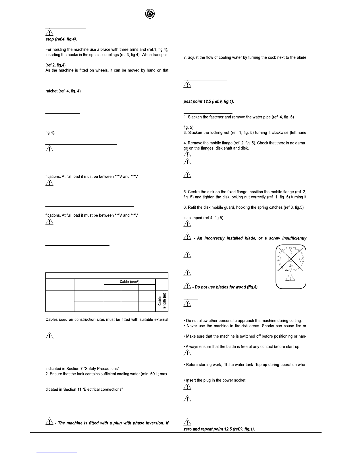
11.3 Sizing the power supply cable
The power supply line must be suitably sized to prevent voltage drops.
Do not use cable winders. The electric cable wire size must take into
account the operating currents and length of the line to avoid excessive
voltage drops (table 4).
Table 4
Model
Type of motor
1.5 2.5 4.0
Masonry 700
Single-phase
Masonry 700
Three-phase
220 V
23.2 A
0 - 12
13 - 24 25 - 50
220 V
22 A
0 - 12
13 - 24 25 - 50
sheathing that is resistant to wear, crushing and extreme weather conditions (for example H07RN-F).
- All power supply installations must comply with CEI 64-8
standards (harmonised document CENELEC HD384).
12. MACHINE START-UP
Before connecting the machine to the power supply:
1. Ensure that the metal structure is connected to an earthing plant as
90 L).
3. Ensure that the power circuit corresponds to the requirements as in-
4. Connect the machine to the power supply
5. Turn the start-stop selector to the start position (star connection). Wait
for 5 sec. and turn to the running position (delta connection).
6. Check that the direction of blade rotation corresponds to that indicated by the arrow on the blade guard.
the direction of rotation of the disk is the opposite of the arrow on
the protective guard, disconnect the power socket from the plug
on the machine and invert a phase. To do this, exchange the two
mobile terminals on the poles using a screwdriver. This operation
is carried out without removing the plug working on the rotary element that holds the mobile poles.
guard (do not perform cutting without water).
8. If all is in order, proceed with cutting.
13. EMERGENCY STOP
- In the case of an emergency, stop the machine pressing the
special red mushroom button. To start again, reset the mushroom
button turning it clockwise and turn the selector to zero, then re-
14. BLADE INSTALLATION
2.Release the spring catches clamping the disk mobile guard (ref. 3,
thread).
- Never use worn blades or blades with missing segments.
- Only use blades that are designed for the number of revolu-
tions indicated on the machine rating plate.
- Check that the direction of rotation of the disk is as shown
on the disk guard.
counter-clockwise (left-hand thread).
7. Put the water pipe back in place and tighten the fastener until the pipe
Fig. 6
- Ensure that the blade guard (ref.3) is locked securely into
position.
tightened can provoke damage to the machine
or injury to persons.
- Note that the blade must have an external
diameter of 700 mm, a central hole diameter of
25.4 mm and max. thickness of 4 mm.
- Check that the blade to be used is suitable
for the material to be cut.
15. USE
- Leave a space of 150 cm around the machine to operate in
full safety.
explosions.
dling.
- Ensure correct installation of all protective devices.
never necessary: N.B. the pump suction hose must always remain immersed in water.
- For safety purposes the removal of protective guards from
the machine is strictly prohibited.
- The machine is protected against overload: this protection
triggers stopping the machine, after which the time necessary for
the overload to cool must pass before it is possible to restart the
machine.
- To resume work after a voltage cut-off, turn the selector to
 Loading...