

IMER 1188174, COMBI 250/1000 VA, COMBI 250/1500 VA, 1188180 Operating, Maintenance, Spare Parts Manual
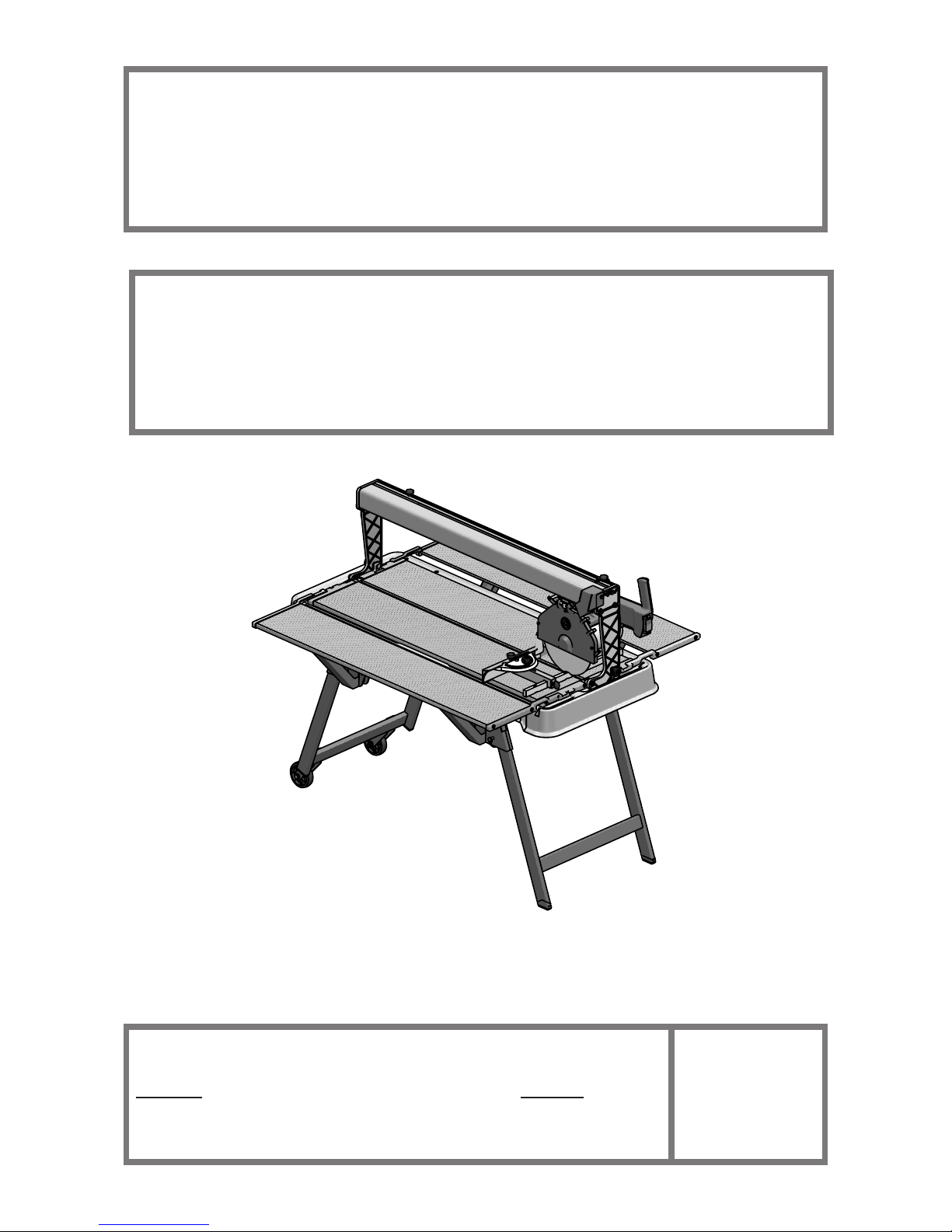
COMBI 250/1000 VA
SAWING MACHINE
1188174
OPERATING, MAINTENANCE, SPARE PARTS MANUAL
IMER WEST
3654, Enterprise Avenue
Hayward, CA 94545
Ph. 510.670.7970
Fax 510.783.4255
IMER EAST
221 Westhampton Place
Capitol Heights, MD 20743
Ph. 301.336.3700
Fax 301.336.6687
IMER U.S.A. Inc.
Toll Free: 800.275.5463
www.imerusa.com
info@imerusa.com
2016/10 - R11
Cod. 3227118
COMBI 250/1500 VA
SAWING MACHINE
1188180
IMER U.S.A. Inc.
COMBI 250/1000 VA - COMBI 250/1500 VA
2
Dear Customer,
Congratulations on your choice of purchase: IMER saws are the result
of years of experience and are equipped with all the latest technical
innovations.
- WORKING IN SAFETY
To work in complete safety, read the following instructions carefully.
To work in complete safety, read the following instructions carefully before using the machine.
To work in complete safety, read the following instructions carefully before using the machine.
This OPERATION AND MAINTENANCE manual must be kept on site
by the person in charge, e.g. the SITE FOREMAN, and must always be
available for consultation.
The manual is to be considered integral part of the machine and must
be kept for future reference (EN 12100-2) until the machine is disposed
of. If the manual is damaged or lost, a replacement may be requested
from the manufacturer.
The manual contains important information regarding site preparation,
machine use, maintenance procedures, and requests for spare parts.
Nevertheless, the installer and the operator must both have adequate
experience and knowledge of the machine prior to use.
To guarantee complete safety of the operator, safe operation and long
life of equipment, follow the instructions in this manual carefully, and
observe all safety standards currently in force for the prevention of accidents at work (use of safety footwear and suitable clothing, helmets,
gloves, goggles etc.).
- Make sure that all signs are legible.
- It is strictly forbidden to carry out any form of modication to
the steel structure or working parts of the machine.
IMER INTERNATIONAL declines all responsibility for failure to comply with laws and standards governing the use of this equipment, in
particular; improper use, defective power supply, lack of maintenance,
unauthorised modications, and partial or total failure to observe the
instructions contained in this manual.
IMER INTERNATIONAL reserves the right to modify features of the saw
and contents of this manual, without the obligation to update previous
machines and/or manuals.
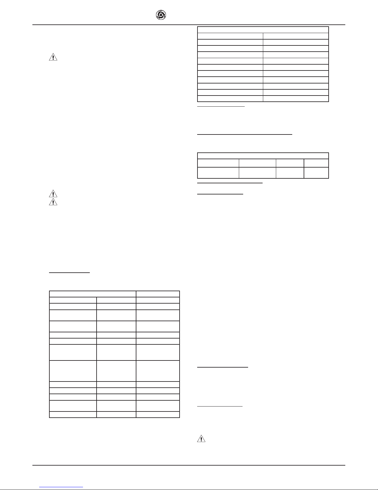
1. TECHNICAL DATA
Technical data are stated in table 1 and electrical specications in table
2.
Table 1 - TECHNICAL DATA
Model Combi 250/1000 VA Combi 250/1500 VA
Max. blade diameter 10 inches 10 inches
Diamond Blade hole
diameter
5/8 inches 5/8 inches
Single phase 115V/60Hz
motor power
1.3 kW 1.3 kW
Max. blade rotation speed 3400 rpm 3400 rpm
Cutting table dimensions 1115x500 mm 1615 x500 mm
Length of 90° cuts
(thickness= 10mm)
Length of cuts from above
950 mm
1000 mm
1450 mm
1500 mm
Maximum cut depth with
single stroke
Maximum cut depth with
two stroke
66 mm
105 mm
66 mm
105 mm
Water pump ow rate 13 l/min 13 L/min
Water tank capacity 40 L 50 L
Machine dimensions 1420x636x619 mm 1920x636x619 mm
Packed machine
dimensions
1454x669x654 mm 1954x669x654 mm
Weight with packaging 65 kg 80 kg
Table 2
Feature Motor (115V/60Hz)
Power (kW) 1.3
Rated voltage (V) 115
Frequency (Hz) 60
Absorbed current 14.4
Number of poles 2
rpm 3400
Service type S6 40%
Insulation category F
Protection category IP55
Capacitor (µF) 110 (Ø 50x120)
2. DESIGN STANDARDS
Combi 250/1000 VA saws have been designed and manufactured according to the following standards: UNI EN 12418:2001; EN 121001/2:2005; EN 60204-1:2006.
3. SOUND PRESSURE LEVEL AND VIBRATIONS
Table 3 shows the sound pressure level measured loadless at the operator’s ear (LpA) and of the vibrations transmitted during operation.
Table 3
Model Type of motor L
pA
A
eq
Combi 250/1000 VA -
250/1500 VA
Electric 86 dB 2.57 m/s
2
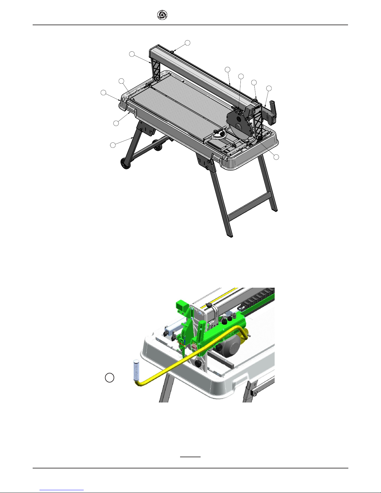
4. GENERAL SAW DESCRIPTION
4.1 General description
The Combi 250/1000 VA (250/1500 VA)is a saw comprising the following
main sub-groups:
• cutter head (ref.A, g.1)
• runner guide and arms (ref.B, g.1)
• cutting tables and heads (ref.C, g.1)
• water collection tank (ref.D, g.1)
• frame (ref.E, g.1)
The cutting head is mounted on a reinforced aluminium prole and is
equipped with horizontal and vertical movement facilities. The alumi-
nium prole is hinged onto die-cast arms (ref.F, g.1) and the entire
unit can rotate through 45° (g.2) by means of the relative handwheels
(ref.G, g.2).
The machine is supported by a special metallic frame. There is a
shockproof plastic tank between the machine and the frame. The water
immersion pump is mounted below the cutting surfaces on a special bracket and supplies a water distributor inside the blade guard for cooling
the cutting blade during operation.
The high resistance plastic handle (ref.H, g.2), is equipped with the
main ON-OFF switch on the operator side to facilitate saw activation
and shutdown.The raised position of the red OFF button on the handle is
designed to facilitate shutdown of the machine in the event of an emergency. The motor capacitor is located in a protected position inside the
handle.
The saw is tted with a guard to guarantee optimal safety during operation and to protect the user during cutting cycles.
A valve is mounted above the blade guard to adjust the ow rate of water
delivered to the cutting blade. The version 250/1500 Va the movement
for the cutting head it is possible by the handle (rif Q, g 1)
4.2 Processable materials
This saw has been designed for cutting the following materials: ceramic
tiles, masonry and stone in general with maximum dimensions compatible with the length, cutting depth and dimensions of the surfaces
specied in table 1.
Maximum weight of processable materials: 25 kg.
4.3 Unsuitable material
Materials unsuitable for this machine are all those not specied in paragraph 4.2.
In any event, before using the saw with materials other than as specied
by the manufacturer for this saw model, contact IMER INTERNATIONAL
S.p.A.
- Use of this machine with workpieces outside the specied
dimensions is strictly prohibited and constitutes a hazard for the
operator.
IMER U.S.A. Inc.
COMBI 250/1000 VA - COMBI 250/1500 VA
3
5. OPERATION SAFETY
- Before using the saw, ensure that all protection devices are
tted.
- Never use the saw in environments subject to the risk of
explosions or re.
The saw is not tted with specic lighting and therefore the workplace
must be sufciently lit for this purpose (min. 300 lux).
The power lines must be laid to prevent any possible damage.
Ensure that the electrical connection is protected against the risk of water penetration in connectors. Use exclusively connectors and couplings
equipped with water spray protection.
Never use inadequate or makeshift electrical lines or cables without
earthing; if in doubt consult a specialised technician.
Repairs to the electrical circuit must be performed exclusively by specialised personnel. Disconnect the machine from the power supply before
performing maintenance or repairs.
6. GENERAL SAFETY WARNINGS
Note that this machine has been designed to ensure optimal performance and maximum safety: however the operator must also guarantee this
level of safety by paying special attention to the machine throughout all
work phases.
1. Ensure that an efcient earthing system is installed.
2. Work only with all protection devices tted correctly and in ef-
cient working order.
3. Remove rings, watches, bracelets or ties before using the machine; these elements constitute a serious hazard to the operator.
Also ensure that sleeves are tight around the wrists, hair is tied
back and robust footwear is used.
4. Always use personal protection devices such as safety goggles,
suitably sized gloves, ear muffs or plugs and hair caps when necessary.
5. Never cut workpieces that have dimensions or weight that are
not suited to machine i capacity as specied by the manufacturer
(see point 4.2)
6. Always keep your hands away from the work areas when the
machine is running. Before taking any action to remove a piece
from close to the disc, stop rotation by pressing the stop button.
7. Keep the machine clean: general cleaning (and the work surfaces in particular) represents an important safety factor.
8. Always stop the machine and disconnect from the power supply
before cleaning or removing any protection device (for maintenance or disassembly purposes). If water jets are used for cleaning,
never point jets directly at the power supply unit or electric motor.
9. Use genuine diamond blades as recommended by the manufacturer to ensure optimal performance of the machine.
10. Use exclusively water-cooled continuous rim blades suited to
the material to be cut.
11. Never dry cut material or cut when cooling water levels are low.
12. Never use blades over the rotation speed specied by the manufacturer.
13. Do not use reduction rings to adapt the hole of the disc on the
ange. Only use discs with hole corresponding to the ange supplied with the machine (1" or 7/8").
14. Never use diamond blades that are chipped or deformed.
15. The instructions in this manual are aimed at machine users
(operators, maintenance engineers).
7. SAFETY DEVICES
The Combi 250/1000 VA(250/1500 VA) has been constructed taking into
account current harmonised European safety standards.
According to machine directive 98/37/EEC all safety devices have been
installed with the aim of safeguarding the operator.
7.1 Guards and safety devices
The machine is equipped with xed guards, secured by means of screws
and protections that prevent access to moving or dangerous parts.
All xed guards, covers, shields xed by means of screws have been
envisaged to protect the operator (maintenance engineers, technicians
and others) from possible accidents cause by electrical discharge or
moving mechanical parts.
Therefore use of the machine with guards removed or modied in any
way is strictly prohibited.
- Before performing maintenance or repairs to the machine,
turn it off via the main switch and disconnect from the power sup-
ply to prevent inadvertent start-up and isolate all machine electrical circuits.
8. MACHINE INSTALLATION
8.1 Set up
Remove the machine packing.
The machine can already be used, leaving the legs folded, resting its
frame on a sufciently even surface at least as big as the tank.
Frame assembly:
1. remove the machine and tank from the folded frame.
2. remove the safety pins from the frame and open the legs.
3. put the safety pins back in the holes provided locking the legs in the
open position.
4. reposition the machine and tank on the frame.
- Make sure that the frame is positioned on a at and even surface, capable of bearing the weight of the machine. The maximum
permissible gradient in all directions is 6°.
8.2 Handling
The Combi 250/1000 VA sawing machine weighs 57 Kg(250/1500 VA
80 kg) and can be moved using the side handles on the tank (ref.I,
g.1). For short distances use the wheels tted on the frame. For longer
distances, before moving the machine, close the frame reversing the
sequence of the operations described in point 8.1.
Every time the machine is moved, make sure the head is locked tighte-
ning the knobs (ref.L, g.1).
- Always empty the tank before moving the machine.
- Always disconnect the power plug before moving the machine.
8.3 Additional table assembly (optional kit code 1188176)
The additional table can be installed to the left or right of the machine, or
on both sides at the same time.
First t the cross member (ref.5, g.6) to the bolts on the frame (ref.A,
g.6) and secure it with the nut and washer (ref.6-7, g.6). Secure the
other end of the cross member with the locking pin (ref.8, g.6) on the
front legs.
Fit the strut (ref.1, g.6) to the cross member, making sure that it locates
into the grooves, which hold it perfectly vertical.
Now install the additional table; it is supplied with the side mounts already assembled. Fit the mounts into the provided cavities in the side
panels of the machine, making sure they are fully inserted. Now lower
the additional table until it is properly supported. Level the additional
table with that of the machine itself; to do this, move the strut to the left
or right along the cross member (g.6).
- The use of additional tables without props can cause damage
to them.
9. ELECTRICAL CONNECTION
- Ensure that voltage corresponds to machine dataplate spe-
cications.
The power supply line must be equipped with current overload protection (e.g. thermal cutout) and protection against indirect contact (e.g.
residual current circuit breaker).
Connect the machine to an efcient earthing system.
The size of the power cable wires must be based on operating current
and length of the power line to prevent excessive voltage drops (table
4).
Table 4
Model Type of motor
Cable (mm²)
1.5 2.5 4.0
Combi 250/1000 VA
-250/1500 VA
115 V
14.4 A
0 ÷ 12 13 ÷ 20 21 ÷ 32
Cable
length (m)
Connect the saw plug to the mains and tighten the mechanical retainer
ring with IP67 protection rating.
The saw is now ready for operation.
IMER U.S.A. Inc.
COMBI 250/1000 VA - COMBI 250/1500 VA
4
10. MACHINE USE
10.1 Operation
The correct side for the operator is shown in g.4 ref.X.
Fill the water tank to the maximum level (approx. 40 litres).
Connect the machine to the power mains and start as described in paragraph 10.
Open the valve (ref.N, g.1) and ensure sufcient ow of cooling water
to the diamond blade.
10.2 Cutting
Rest the material to be cut on the cutting table against the stopper. De-
ne the required inclination using the goniometer. To adjust the cutting
head height, loosen the handwheel (ref.O, g.3), position the head at
the required height, then fully tighten the handwheel. Make sure that
handwheels for sloped cutting (ref.G, g.2) are rmly tightened. Start the
sawing machine as described in paragraph 10. To proceed with cutting,
press the piece to be cut on the table with your hand and move the cutter
head gripping the handle and drawing it towards you. If the feed speed
is too fast in relation to the thickness and hardness of the material the
blade might stop turning. In this case, release the disk as quickly as
possible moving the cutter head away from you until the disk recovers
its nominal rotation speed. Resume cutting, adjusting the feed speed
according to the characteristics of the material.
10.3 Angled cuts
Loosen the handwheels (ref.G, g.2), set the cutting head at the required angle, retighten the handwheels, and proceed as described in the
point above.
- Ensure that the tank is kept full during all work phases and in
the event of prolonged work intervals replace water regularly and
remove all processing residue.
10.4 Laser pointer
The machine is tted with a laser pointer that reproduces the cutting line
on the piece being machined. The track of light indicates the trajectory
of the diamond disk during the feed motion. Making the required cutting
prole coincide with the laser prole, it is possible to ensure the highest
accuracy of the operation.
Cuts at right angle with one side of the piece being machined do not re-
quire tracing beforehand: in fact it will sufce to make sure that the side
of reference is in contact with the stopper on the resting surface. Likewi-
se, using the goniometer, cutting at predened inclinations is possible.
The laser light will indicate the actual position of the cut.
The laser pointer is activated when the machine is connected to the
electric mains.
The pointer is aligned with the disk and must not be moved from its
initial position.
- The pointer used emits a low power laser light, but it is in any
case advisable to avoid looking directly at the emitter itself.
11. MAINTENANCE
11.1 Premise
Routine maintenance operations can also be performed by non-speciali-
sed personnel provided that all safety standards specied in the relative
sections of this manual are observed at all times.
11.2 Machine cleaning
The machine should be cleaned exclusively when it is stationary.
- All power switches must be set to “0” and plugs must be
disconnected from the mains.
1. Never use compressed air; this could cause inltration of dust or residue in enclosed parts.
2. Ensure that the cooling water nozzles are not obstructed.
3. Above all the cooling water in the tank must be changed every day.
4. Do not use detergents or lubricants.
11.3 Cleaning the tank
Clean the tank in the event of build-up of sediment on the base, or at least once a day. Failure to clean the tank could impair operation of the immersion pump used for circulation of the diamond blade cooling water.
To clean the tank, disassemble from the machine, lock the head, hold it
by the arms and rinse with a direct water jet (this is to avoid direct contact of the water with electrical parts), the proceed with manual cleaning
using cloths or brushes.
Take care not to damage cables when replacing the machine on the tank
Take care not to damage the pump when placing the machine on the
surface
11.4 Cleaning the cooling water supply circuit
At regular intervals (or when the ow rate of the blade cooling water is
reduced) clean the cooling water supply circuit. To do this, disassemble
the delivery nozzle (ref.P, g.1) located inside the blade guard and clean
in water.
Periodically clean the cooling water delivery line between the pump and
valve and blade guard using water.
11.5 Blade replacement
The diamond blade is made of material that may be damaged when
subject to high temperatures, and therefore must be cooled during the
work phases.
To replace the blade, proceed as follows:
1. Block axial movement of the cutting head by means of the handwhe-
els (ref.L, g.1).
2. Disassemble the front guard (ref.P, g.1).
3. Loosen the locknut by rotating clockwise (left thread), using a 19 mm
wrench.
4. Move the cutting head forward slightly and incline to remove the blade
from its seat.
5. Ensure that there are no foreign objects between the xing ange and
diamond blade. During disassembly, avoid use of tools that could dent
or deform the ange.
6. Insert the new blade proceeding in reverse order of the operation
described at point 4. Take special care to ensure correct direction of
rotation of the diamond blade.
7. Tighten the blade locknut fully down by rotating anticlockwise (left
thread), to a torque of 40 Nm.
- Always disconnect the power plug before changing the disk.
11.6 Repairs
Repairs to the electrical installation must be performed exclusively by
specialised personnel. Use exclusively original IMER spare parts; modi-
cations to parts are strictly prohibited. The special design of the Combi
250/1000 VA ensures that no other maintenance other than as specied
above is required.
Ensure that the contacts of the power plug and plug-switch assembly
are efcient. If oxidation is detected, clean immediately
- In the event of activation of the RCCB, check the machine
and arrange for repairs if necessary exclusively by specialised
personnel.
11.7 Waste disposal
As regards disposal of processing waste observe all current legislation
in the country of use.
IMER U.S.A. Inc.
COMBI 250/1000 VA - COMBI 250/1500 VA
5
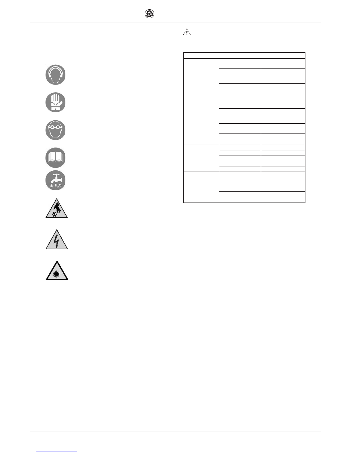
12. Residual risks and safety signs
Although the sawing machine has been manufactured fully in compliance with current regulations, residual risks exist that cannot be eliminated
and involve the use of appropriate individual protection devices. Ade-
quate warning signs tted on the machine point out both the risks and
the behaviour to be followed.
NOISE RISK
Ear protection must be worn
RISK OF INJURY TO THE HANDS
Safety gloves must be worn
RISK OF INJURY TO THE EYES
Eye protection must be worn
ABNORMAL USE RISK
Reading the manual before use is compulsory
Cutting with water is compulsory
DANGER OF CUTTING
DANGER OF ELECTROCUTION
DANGER OF LASER BEAM
Please be reminded that checking the use of IPDs is delegated to the
employer.
14. Troubleshooting
- CAUTION!!! All maintenance operations must be performed
exclusively with the machine switched off, with the selector set to
“0” and the power plug disconnected from the mains.
Trouble Causes Remedies
The motor does not
start when the start
switch is pressed
Current does not reach
the supply line
Check the line *
The socket and plug
are not connected
properly
Restore correct
connection
The differential switch
is off
Turn the differential
switch on
The power cable from
the plug to the panel
is cut off
Change the cable *
An electric wire inside
the motor terminal strip
is cut off
Restore the connection *
An electric wire inside
the panel is cut off
Change the switch *
The start switch is
faulty
Change the switch *
Cooling water fails
to reach the blade
Low water level in tank Restore the water level
Pump lter clogged Clean the pump lter
Current fails to reach
the pump
Check the pump
electrical supply *
Pump failure Change the pump *
The blade does
not cut
Blade tted in the
opposite direction to
that of rotation
Remove the blade
and reposition it in the
direction shown on the
blade label
Worn blade Change the blade
* Operation to be carried out by an electrician
IMER U.S.A. Inc.
COMBI 250/1000 VA - COMBI 250/1500 VA
6
A
B
C
E
D
F
I
L
L
N
P
FIG. 1
Q
 Loading...