

IMER 1188616 Manual Instruction And Parts List
U.S.A. inc.
TD 10 Sawing machine
EL
R
MANUAL INSTRUCTION
and
PARTS LIST
Model - 1188616
Machine serial N°
Manual Part. number 3223601_R00 (2003/11)
Write in the serial n° of your machine here
2
IMER U.S.A. Inc.
TD 10
Special attention must be given to warnings with this symbol:
Thank-you for purchasing a TD 10 from an Imer U.S.A. dealer. Your decision is an intelligent one.
There is no other sawing machine in the world which delivers the benefits and features of the TD 10:
- Extremely rigid, mig welded bar steel frame.
- Electric motor 1.5 Hp.
.
- Compact design for easy trasportation.
- Extremely rigid worktable for a precise cutting.
At IMER U.S.A. we continually search for ways to better serve our customers. Should you have an idea or thought to
share with us regarding this product we would appreciate hearing from you. Our motto is "Tools and Services for the
21st Century" .
We look forward to delivering the goods.
Thank you again for your purchase.
Mace T. Coleman, Jr.
President, Imer U.S.A, Inc.
IMER WEST
207 Lawrence Avenue
So. San Francisco, CA 94080
Tel 650 - 872 - 2200
Fax 650 - 873 - 6482
IMER EAST
221 Westhampton Place
Capitol Heights, MD 20743
Tel 301 - 336 - 3700
Fax 301 - 336 - 6681
14
1
2
3
4
5
6
7
8
9
10
11
12
13
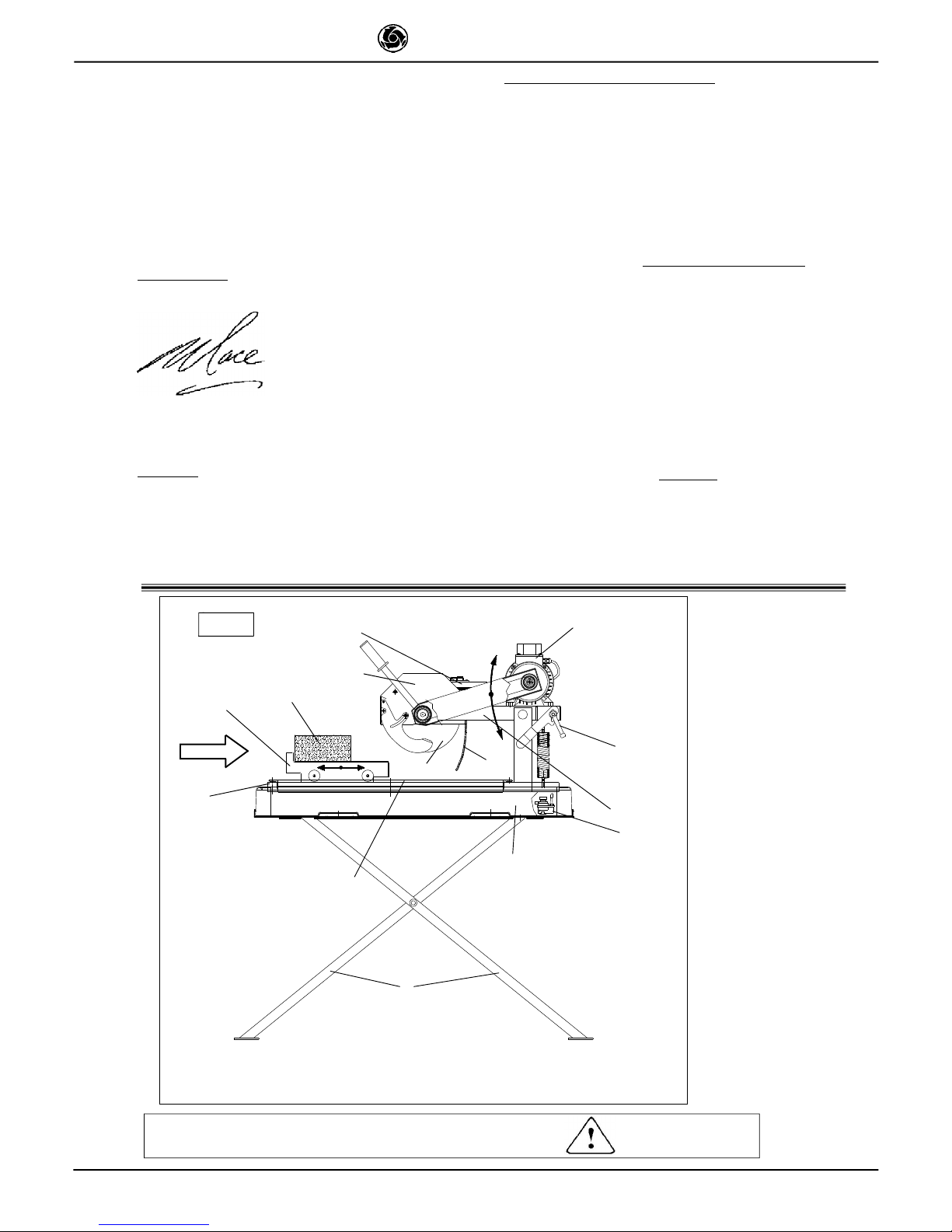
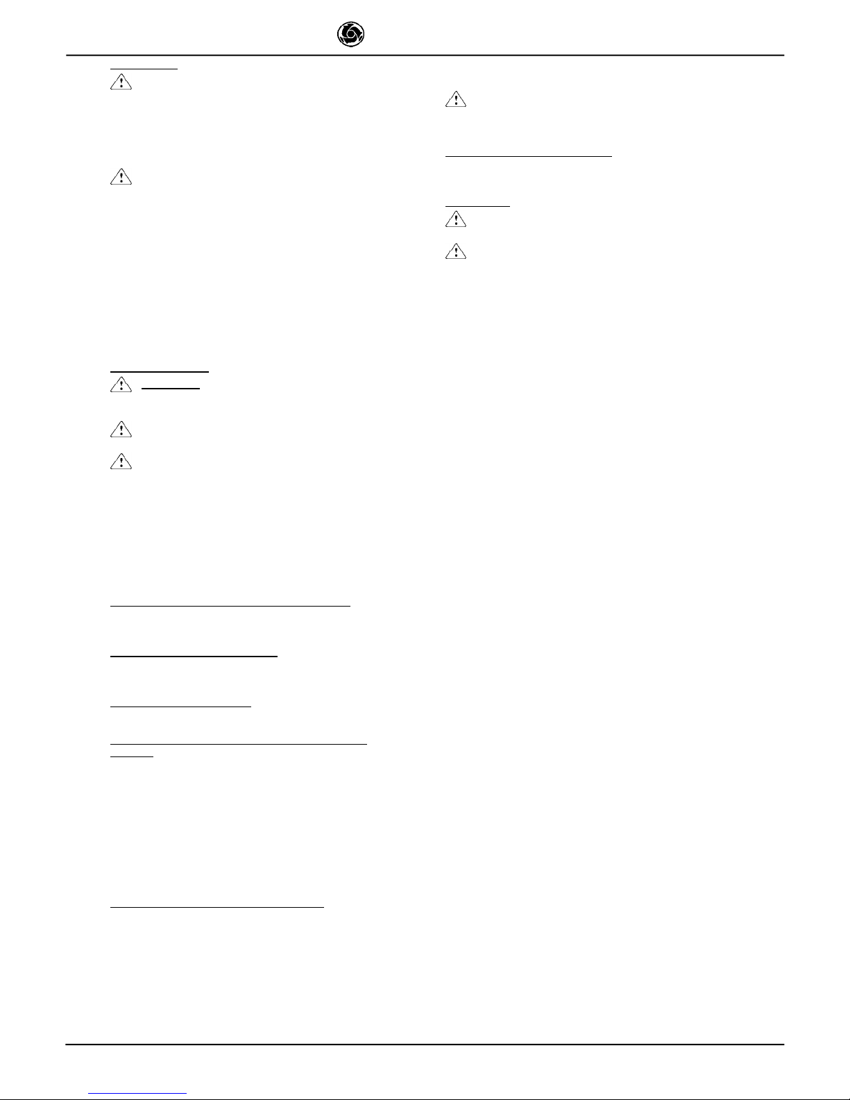
Fig. 1
1. Trestle element
2. Spray guard
3. Motor
4. Blade support
5. Water pump
6. Guide
7. Junction box
8. Worktable
9. Water tank
10. Blade guard
11. Support locking handle
12. Work piece
13. Blade
14. Frame
15. Disc cover
X
3
IMER U.S.A. Inc.
TD 10
Dear Customer,
Congratulations on your choice of purchase: this IMER saw, the
result of years of experience, is a fully reliable machine and is
equipped with the latest technical innovations.
- WORKING IN SAFETY
To work in complete safety, read the following
instructions carefully.
- This OPERATION AND MAINTENANCE manual must be kept on
site by the person in charge, e.g. the SITE FOREMAN, and must
always be available for consultation.
- The manual is to be considered part of the machine and must be
kept for future reference (EN 292/2) until the machine is disposed
of. If the manual is damaged or lost, a replacement may be
requested from the saw manufacturer.
- The manual contains important information regarding site
preparation, installation, machine use, maintenance procedures
and requests for spare parts. Nevertheless, the installer and the
operator must both have adequate experience and knowledge
of the machine prior to use.
- To guarantee complete safety of the operator, safe operation
and long life of equipment, follow the instructions in this manual
carefully, and observe all safety standards currently in force for
the prevention of accidents at work. Use personal protection
(safety footwear, suitable clothing, gloves, goggles, etc.).
- Safety glasses or a protective visor must be worn at all
times.
- Ear protection must be worn at all times.
- MAKE SURE THAT WARNING SIGNS ARE ALWAYS
LEGIBLE.
- It is strictly forbidden to carry out any form of
modification to the steel structure or working parts of the
machine.
- IMER INTERNATIONAL declines all responsibility for noncompliance with laws and standards governing the use of this
equipment, in particular; improper use, defective power supply,
lack of maintenance, unauthorised modifications, and partial or
total failure to observe the instructions contained in this manual.
IMER INTERNATIONAL is entitled to modify the characteristics of
the sawing machine and/or the contents of this manual without
necessarily updating previous machines and/or manuals.
1. TECHNICAL DATA
Table 1 shows the saw s technical data, referring to figure 1.
2. DESIGN STANDARDS
TD 10 saws are designed and manufactured according to the following
standards: EN 292-1-2; EN 12418; EN 60204-1.
TABLE 1
TECHNICAL DATA 1188616
Blade rpm rpm 3400
Blade diameter in. 10
Blade mounting hole in. 5/8
Motor rating Hp 1.5
Voltage V 115
Current A 14.4
Frequency Hz 60
Motor rpm rpm 3600
Cutting table dimension in. 12" x 14"
Overall dimensions
(widthxlengthxheight)
in. 23½" x 42½" x 23¼"
Overall dimensions for
transport
(widthxlengthxheight)
in. 24" x 43" x 23½"
Water pump flow rate L/min 10
Water tank capacity L 42
Weight lb. 117
Weight for transport lb. 134
Blade rotation direction(seen
from blade clamping flange)
CLOCKWISE
3. NOISE EMISSION LEVEL
Table 2 indicates the noise level produced by the sawing machine,
measured at the operator s ear (L
pA
at 1 m - 98/37CE) and the
environmental noise emission level (power LWA) measured in
accordance with EN ISO 3744; UNI EN 12418.
4. CUTTING SPECIFICATIONS
This saw model has been specially designed for cutting stone,
ceramics, marble, granite, concrete and similar materials. Only
water-cooled diamond blades with continuous or segmented
edges (see paragraph 14) must be used. Under no
circumstances must dry cutting blades be used or materials
other than those specified above. IMER INTERNATIONAL
declines all responsibility for damage caused by improper use
of the above machine.
5. CUTTING CAPACITY
- max. cutting capacity with vertical blade = 3¼" in. in one
single pass.
- max. height of workpiece: 4¾" in. (in two passes).
- min. width of workpiece: 2" in.
- max. cutting length: 15" in. (with blade lowered), 19¾" in.
(for max cutting height in one single pass).
-Blade at 45°: with support at 45° on the work surface.
6. WARNING
- Do not load the saw with workpieces that exceed the specified
weight (max. 55 lb.)
- Ensure stability of machine: it must be installed on a solid
base with a maximum slope of 5° (fig. 2).
- Ensure the workpiece is stable before, during and after cutting:
in any case, workpieces must not overhang the worktable.
- Respect the environment; use suitable receptacles for
collection of cooling water contaminated with cutting dust.
7. SAFETY PRECAUTIONS
- IMER saws are designed for work on construction sites and
under conditions of natural light, hence the workplace must be
adequately lit.
- The machine must never be used in environments
subject to risks of explosion and/or underground sites
- IMER saws may only be used when fitted with all required
safety devices, which must be in perfect condition.
- Never use makeshift and/or faulty power cables.
- Make electrical connections on the construction site where
they will not be subject to damage. Never stand the saw on
power supply cables.
- Lay power cables in such a way as to prevent water
penetration. Only use connectors fitted with water-spray
protection (IP67, EEC).
- Repairs to electrical installations must only be carried out by
qualified technicians. Always ensure that the machine is
disconnected from the power supply and is completely immobile during repairs and maintenance operations.
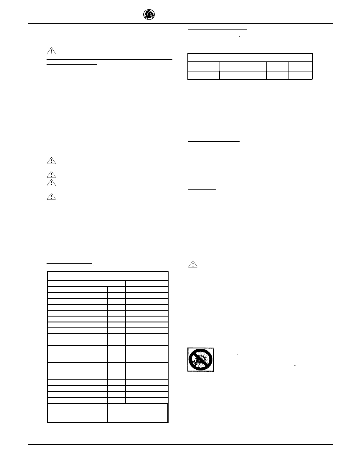
- The symbol shown on the label (see left) indicates
the warning ENSURE ALL PROTECTION DEVICES
ARE INSTALLED AND IN PERFECT CONDITION
BEFORE SWITCHING ON THE MACHINE (fig.3).
8. ELECTRICAL SAFETY
IMER saws comply with EN 60204-1; and are fitted with:
- Protection device against automatic re-start after power failure.
- Short-circuit cutout device
- Motor overload cutout switch
Fig. 3
TABLE 2
SAWING MACHINE TYPE OF MOTOR
L
p
A
(dB) LWA(dB)
TD 10 ELECTRIC 82 92
4
IMER U.S.A. Inc.
TD 10
9. TRANSPORTATION
- WARNING!
Before moving the saw, lock head
support carriage movement by means of the relative knob
(Ref. 11, fig. 1).
The saw weights 117 lb and can be moved by means of the
side handles on the tank.
Always empty the tank before moving the machine.
10. INSTALLATION
The machine must be placed on a smooth surface that is at least
as large as the tank, with the saw on the relative stand (Ref. 11,
fig. 1).The correct side for the operator is as shown in Fig.1
position X.
- Ensure that the stand is positioned on the relative
inserts on the tank base and thus secured.
- Always remove the plug from the mains power before
moving the machine.
11. ELECTRICAL CONNECTION
Connect the mains power cable to the plug on the electrical
panel.
- Ensure that the electric line has a suitable
differential overload switch(RCD)(GFCI-USA).
THERMAL CUTOUT PROTECTION:
- The electric motor is protected against overload by
a thermal cutout; in the event of overheating this device
shuts down the motor.
Cool the motor and restart by means of the RCCB
switch and the main switch on the handle .
The machine is protected against short circuits by a
magnetic protection inside the RCCB.
-Ensure that the mains voltage corresponds to that specified
for the machine: 115/60Hz. The electrical power cable must be
suitably sized to avoid voltage drops. Cable drums must not be
used.
Cables used on construction sites must be fitted with suitable
external sheathing that is resistant to wear, crushing and
extreme weather conditions (for example H07RN-F).
- All power supply installations must comply with
CEI 64-8 standards (harmonised document CENELEC
HD384).
12. MACHINE START-UP
Before connecting the machine to the power supply:
1 - Ensure that the tank contains sufficient cooling water.
2-Connect the power supply cable to the electric panel plug.
3-Turn on the concrete mixer using the switch located on the
electric control panel (ref. 7, fig. 1) comprising two buttons: the
green one switches on the machine, while the red one switches
it off. The switch has minimum voltage protection: after a power
failure or accidental power loss, push the green start button to
start the machine up again.
4 - Check that the direction of blade rotation corresponds to that
indicated by the arrow on the blade guard.
Open the valve and ensure sufficient flow of cooling water to
the diamond blade.
5 - Never dry cut material or cut when cooling water levels
are low.
6 - If all is in order, proceed with cutting.
13. EMERGENCY STOP
- In case of an emergency, stop the machine by
pressing the red stop button (extended), then disconnect
the plug from the power supply socket.
- The motor is protected against automatic re-start
after interruptions due to power failure. To resume
operation, when power is re-connected, press the green
switch on the overload cutout device.
14. BLADE INSTALLATION
Always remove the plug from the mains power.
- Note that the blade must have an external diameter of
10"in., a central hole diameter of 5/8"in. and max. thickness
of 1\8in.
The diamond blade is made of material that may be damaged
when subject to high temperatures, and therefore must be
cooled during the work phases.
To replace the blade, proceed as follows:
1.Block axial movement of the cutting head by means of the
handwheels (ref.11 fig. 1).
2.Stop the blade rotation fitting the shaft blocking pin (ref. 1 fig.
5) in the hole of the belt cover (ref. 2 fig. 5) rotating the blade
till the pin has entered the hole in the shaft.
Verify that the blade doesn t turn, otherwise repeat the
operation again.
3. Disassemble the front guard.
4. Loosen the locknut by rotating clockwise (left thread),
using a 19 mm wrench.
5. Move the cutting head forward slightly and incline to
remove the blade from its seat.
6. Ensure that there are no foreign objects between the
fixing flange and diamond blade. During disassembly, avoid
use of tools that could dent or deform the flange.
7. Insert the new blade proceeding in reverse order of the
operation described at point 4. Take special care to ensure
correct direction of rotation of the diamond blade.
8. Tighten the blade locknut fully down by rotating
anticlockwise (left thread), to a torque of 40 Nm.
9.Take the shaft blocking pin off the belt cover.
10.Verify the blade turn freely.
11.Connect the plug again.
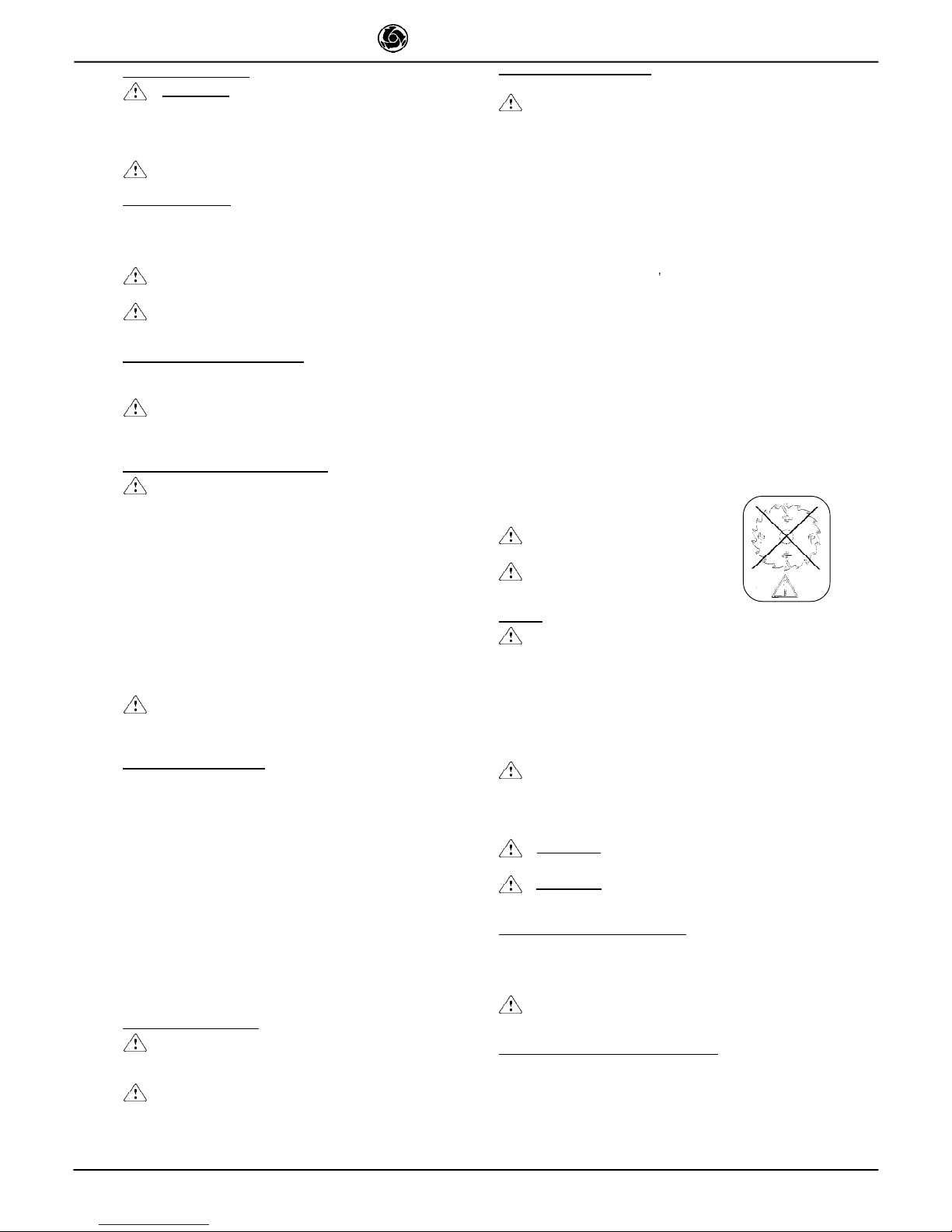
- Check that the blade to be used is
suitable for the material to be cut.
- Do not use blades for wood! (fig. 6).
15. USE
- Leave a space of 5 ft. around the machine to operate
in full safety.
- Do not allow other persons to approach the machine during cutting.
- Never use the machine in fire-risk areas. Sparks can cause fire or
explosions.
- Make sure that the machine is switched off before positioning or
handling.
- Always ensure that the blade is free of any contact before startup.
- Ensure correct installation of all protective devices.
Before starting work, fill the water tank. Top up during operation
whenever necessary: N.B. the pump suction hose must
always remain immersed in water.
- Insert the plug in the power socket.
- WARNING!
For safety purposes the removal of
protective guards from the machine is strictly prohibited
- WARNING! Always switch off the machine before
carrying out blade adjustment.
15.1 VERTICAL BLADE MOVEMENT
To raise or lower the blade, slacken the support locking handle
turning it anti-clockwise (Ref. 11, fig. 1). The blade support (Ref. 4,
fig.1) remains free to rotate, so it can be secured in the desired
position, fully tightening the handle (ref. 11, fig. 1).
- Ensure that the locking handle is tightened fully before
starting work.
15.2 BLADE POSITIONING FOR 45° CUTS
To make a cut at 45°, the 45° support on the carriage is necessary.
Once the workpiece is correctly positioned, cutting can begin, starting
the electric motor.
Fig. 6
5
IMER U.S.A. Inc.
TD 10
15.3 CUTTING
- Check that the blade is aligned with the cutting line.
- Place the workpiece on the worktable (ref. 8, fig. 1), resting firmly
against the stop. Start the motor.
Wait until the water reaches the blade. Begin cutting.
- Horizontal cutting movement is carried out by pulling the carriage
towards the blade.
- As cutting thickness increases, the blade is subjected
to greater stress. To avoid overloading the motor, the
operator should continually check blade feed speed. The
speed will also depend on the characteristics of the
material being cut (hardness, toughness etc.).
15.3.1 CUTS WITH BLADE LOWERED FROM ABOVE
Bring the blade support to its highest position and lock. Position the
workpiece. Start the machine, unlock the blade support and begin
vertical cutting until the blade reaches its lowest point. Lock the
support once more and proceed with horizontal cutting
15.3.2 BLADE CHANGE
To change the blade refer to section 14.
16. MAINTENANCE
- WARNING! Servicing must always be carried out by
qualified technicians and only after the motor has been
switched off.
- Always keep the guards in proper working order
and free from damage.
- As there is the continuous risk of inadvertent
damage to the electric cables, these must be checked
regularly each time before the machine is used.
Never leave the machine out in the open. Make sure that it is
stored in a sheltered area away from extreme weather
conditions.
Below is a list of the cleaning operations that must be carried out
at the end of every shift.
Recommended product for cleaning and lubricating the
mechanical parts of the saw: WD40
16.1 TANK CLEANING ON WORK COMPLETION
- Empty the tank by removing the plug. Remove cutting residue
using a jet of water.
16.2 WORK SURFACE CLEANING
Always keep work surfaces clean. Residual dirt can impair cutting
precision.
16.3 GUIDE RAIL CLEANING
It is good practice to remove all traces of dirt from the guides.
16.4 CLEANING AND MAINTENANCE OF COOLING
CIRCUIT
- If water does not reach the blade stop the machine immediately
to avoid blade damage.
- After switching off the machine ensure that the water level is
sufficient.
At regular intervals (or when the flow rate of the blade cooling
water is reduced) clean the cooling water supply circuit. To do
this, disassemble the delivery nozzle located inside the blade
guard and clean in water.
Periodically clean the cooling water delivery line between the
pump and valve, and blade guard using water.
16.5 TENSIONING THE DRIVE BELT (fig. 3)
- Switch off the electric motor and remove the plug from the
power supply.
- Unscrew the 4 screws that secure the movable belt guard (ref. 1).
- Loosen the 4 (ref. 2) screws that clamp the electric motor to
the blade support.
- Tension the belt using the nut (ref. 3): apply a force of about
F=14 lb. to the centre of the free section of the belt, the arrow
should be about f=1/4" in. (fig. 4).
- Tighten the screws on the electric motor, checking the alignment
of the motor pulley and the blade pulley
- Refit the guard and lock it using the 4 screws.
- To avoid shortening the life of the belt, the bearings
and the blade shaft, do not overtension the belt. Finally,
check the two pulleys are aligned.
16.6 DRIVE BELT REPLACEMENT
Repeat the operations described in section 16.5, replacing the
belt before tensioning it
17. REPAIRS
- Do not start the saw during repair work.
Only use genuine IMER spare parts and do not modify them.
- If the guards are removed to carry out repairs, they
must be refitted properly when the repair work is finished.
 Loading...