

Imed Gemini PC-4 Service manual (2000)

Jp^
Cut
and
insert
into
label
on spine of
binder
holder
PC-4
WARNINGS,
CAUTIONS
AND
NOTICES
CAUTION: FEDERAL
THE
ORDER
USE
ONLY
GROUNDING.
CONNECTION
OFAPHYSICIAN.
HOSPITAL
GROUNDING
TOARECEPTACLE
DANGER:
WARNING:
(USA)
GRADE
EXPLOSION
FLAMMABLE
TO
WHEN
LAW
RESTRICTS THIS DEVICE TO SALE BYOR ON
POWER
RELIABILITY
HAZARD,
ANESTHETICS.
PREVENT
FLO-STOP
SUPPLY
CAN
ONLY
MARKED
DO
"HOSPITAL
NOT
USEINTHE
UNRESTRICTED
IS
OPEN.
CORD
TO
BE
ACHIEVED
GRADE".
FLOW,
INSURE
PROPER
PRESENCE
CLOSE
BY
OF
CLAMP
/
CAUTION:
$
TO
REDUCE
COVER
PERSONNEL.
OR
RISK
BACK.
OF
ELECTRICAL
REFER
SERVICING
SHOCK,
TO
DO
NOT
QUALIFIED
REMOVE
SERVICE
/
/ A V
TO
MAXIMIZE
THIS
INSTRUMENT
THE
WARNING:
CAUTION:
SERVICE
BE
LIFE OF THE INSTALLED
STORED
BEFORE
AND
REPLACE
CONNECTING
NOTE
OPERATED
IN
CONTROLLED BETWEEN 68°F (20°C) AND 77°F (25°C).
WARNING
IN
THE
EVENT
BIOMEDICAL
THE
INSTRUMENT IS
TECHNICIAN
PRIOR
DROPPED
TO
USE
AT ANY TIME, IT
FOR
PATIENT
FUSEASMARKED.
"REFER
BATTERY,
AN
ENVIRONMENT
CARE.
TO
IT IS
MUST
MANUAL"
RECOMMENDED
THATISTEMPERATURE
BE
CHECKED
THAT
BY A
WARNINGS,
CAUTIONS
AND
NOTICES
SEfflft
WARNING:
CLAMP WHEN FLO-STOP® IS
/1\
TO
PREVENT
CAUTION:
REFER
/ I \
TYPE CF (Equipment
CLASS
1
r\
^
/ A V
TV
V
ALTERNATING
REPLACE
EQUIPOTENTIAL
EQUIPOTENTIAL
SYSTEM IS IN QUESTION,
INTERNAL
FUSE
BATTERY
UNRESTRICTED
OPEN.
TO
MANUAL
useable
CURRENT
ONLY
WITH
GROUND
EARTH
POWER.
CONNECTION
OPERATE
FLOW,
for
SAME
POINT:IFTHE
direct
TYPE
THE
CLOSE
cardiac
AND
OR
ROLLER
applications)
RATING
INTEGRITY
HOSPITAL
INSTRUMENT USING
OF
EARTH
THE
IPX1
ONLY
should
connection
Only
should
connection
DRIP
equipment
be
connected
should
systems
be
connected
should
PROOF
CAUTION
that
has
been
qualifiedtoIEC 601-1
to
the
PC-4's
RS-232-C
Data
Port
ONLYbeperformed by qualified personnel.
CAUTION
that
have
been
qualifiedtoIEC 601-1
to
the
ONLY
PC-4's
be performed by qualified personnel.
ii
Nurse
Call
connector
standards
and
standards
and
the
the
NOTICE
Product design and/or specifications
change
in
without notice.
this
manualiscurrent
The
information contained
asofthe
date
are
of
This publication contains ALARIS Medical
Systems™ proprietary
use oftechnical personnel inrepairing
data
provided
solely
IMED®
Gemini infusion pump/controllers.
subject to
issue.
for
the
Noneofthe
duplicated nor
information contained herein may be
mayitbe
utilized in any manner
other than forthe repairand maintenance of
Gemini infusion pump/controllers
component
the
information contained herein may subject
usertosubstantial
parts thereof. Any unauthorized
liability.
and
the
IMED8
use
of
the
J^v
77?/s
manual
maynot,inwhole orin
electronicormachine-readable
ALARIS Medical
10221 Wateridge Circle
San
Diego, CA 92121
(858) 458-7000
Systems,
USA
Inc.
part,
be copied,photocopied, reproduced,
form
withoutprior
°Copyright
PrintedinUSA
U.S.
4,954,046; 4,859,927; 4,764,166; 5,219,330; D305.060; D305.151; D352.778. AU 580,184; 586,594;
590,179; 601,664; 607,112; 622,088; 596,552; 604,477. CA 1,235.033; 1,258,212; 1,300,977; 1,280,647;
1,296,791; 2,020,926; 1,296,092; 1,238,832. AT 0.225,158. BE 0,225,158. FR 0,225,158 283,614;
315,312; 0,431,726; 0,238,277. GB 0,225,158; 283,614; 315,312; 0,431,726; 0,238,277. NL 0,225,158
283,614. IT 0,225,158; 283,614. SE
3871721T2;
fcW*1 9 0 2 3 8
OtherUSand
IMED®,
2000
Patents
4,617,014; 4,689,043;
P6908208;
Gemini
ALARIS
Foreign
PC-4*
written
Medical
P3774598. TW
79;
«R*1
Patents
and
Flo-Stop*
in
consentofALARIS Medical Systems,
Systems,
4,690,673;
9 6 7
Issued
Inc.
Ail
4,725,205; 4,728,265; 4,836,752; 4,909,710; 4,920,336;
0,225,158
and
are
283,614. CH 0,225,158. DE P3686558.3; P3772.556.9;
UM52721.JPWW*1754470
16
89;tt»*1
Pending.
registered
Rights
translated,
Reserved
7 9 3119#;»ff«1
orconvertedtoany
trademarksofALARIS
Inc.
^;
WW* 1
Medical
81
7 3 0 3 9
Systems™.
6 8
729;
59.

PC-4
PREFACE
This manual contains operation
instructions for
the
IMED®
and
maintenance
GEMINI PC-4®
series
Volumetric Infusion Pumps/Controllers ("PC-4").
The
information provided herein is intended for use
by technical personnel responsible for servicing
these
products.
sections
andispresentedasfollows:
The
material is divided into
Section
seven
1 -
Description; Section 2 - Preparation for Use;
Section 3 - Operation; Section 4 - Principles of
Operation; Section 5 - Maintenance; Section 6 -
Illustrated
and
Parts
Preventative
Breakdown;
Maintenance.
Section
7 - Calibration
of
Additionalcopies of this manual maybeobtained
by contacting your
nearest
ALARIS Medical
Systems CustomerService Department.
This
manual
Maintenance
PC-4
International
9213-00
1340-9217-00
No.
1340-9217-01.
The
featuresofthe
been
incorporated into this manual. Text
graphics
model
are
P/N143649
and
PC-4
that
are
identified
supersedes
Manual,
and
Part
No.
Addendum,
Maintenance
PCM
Technical
220V
modelofthe
related exclusively to
witha©©
PCM
1340-9201-00
Part
No.
1340-
Manual,
Part
Update,
PC-4
have
or
the
220V
symbol.
and
Part
No.
/"^Iik
IV

IPN
PC-4
j^v
SECTION
SECTION
1 -
DESCRIPTION
1.1
1.2
1.3
1.4
1.5
1.6
1.7
1.8
2 -
PREPARATION
2.1
2.2
2.3
INTRODUCTION
OPERATING
OPERATING
USER
PHYSICAL
PRODUCT
OPERATING
ACCESSORIES
INTRODUCTION
PRE-OPERATIONAL
OPERATIONAL
INTERFACE
DESCRIPTION
HISTORY
FOR
2.3.1 Pre-operational
TABLE
CHARACTERISTICS
CONDITIONS
SPECIFICATIONS
USE
MECHANICAL
PERFORMANCE
Check
Battery
OF
CHECK
Charge
CONTENTS
INSPECTION
1-1
1-1
1-1
1-1
1-3
1-3
1-3
1-3
1-3
2-1
2-1
2-1
2-1
2-3
2.3.2 Pre-operational Electrical Inspection 2-3
2.3.2.1 Electrical
2.3.2.2
Electrical
2.3.3 Abbreviated Operational
2.3.3.1
2.3.3.2
Test
Test
Leakage
Ground
Test
Test
Performance
Test
2-3
2-3
2-3
Requirements 2-3
Procedures
2-3
SECTION3-OPERATION
3.1
3.2
3.3
3.3.1 Normal Operation 3-5
3.3.1.1 Pump Controller
3.3.1.2
3.3.1.3 Independent
3.3.1.4 Monitoror Computer Control
3.4
3.5
3.6
SECTION
4-PRINCIPLES
4.1
4.2
4.2.1 Physical Description 4-1
4.2.1.1 Pumping Mechanism 4-1
4.2.1.2 Strain Beam
4.2.2 Functional Operation 4-1
4.2.2.1 Pumping Mechanism 4-1
4.2.2.2 Strain Beam
4.3
4.3.1 Functional Description 4-5
4.3.2 FunctionalOperation 4-6
4.3.2.1 Power On/Power Off
4.3.2.2 5 Volt Regulator Subsystem 4-6
INTRODUCTION
CONTROLS
OPERATING
System
AND
INDICATORS
CONDITIONS
and
Selectable
Modes 3-5
Configuration 3-5
Setup
and
Operating Procedures 3-6
Setup
and
Operating
Procedures
CHANNEL, CENTRAL INFORMATION DISPLAYS AND ALARM
AUDIO
NURSE
INTRODUCTION
MECHANICAL
ELECTRICAL/ELECTRONIC
ALERT
CALL
OF
OPERATION
SYSTEM
FEATURE
OPERATION
(Pressure
(Pressure
Transducer) 4-1
Transducer) 4-5
OPERATION
Subsystem
RESPONSE
3-1
3-1
3-1
3-5
3-47
PROCEDURES 3-51
3-61
3-61
4-1
4-1
4-1
4-5
4-6
V
PC-4
SECTION
4.3.2.3
4.3.2.4 5
4.3.2.5 Battery
4.3.2.6
±8
VoltDCPower
Volt
Protected Subsystem 4-7 1
Charger
System
Reset
Supply
Subsystem
Subsystem
Circuit 4-8
4"7/«%
4-7
4.3.2.7 Battery Depleted Circuit 4-8
4.3.2.8 Pumping Mechanism 4-8
4.3.2.9
4.3.2.10
4.3.2.11 Slide
4.3.2.12
4.3.2.13
4.3.2.14 Display
4.3.2.15
Strain
Beam
Air-ln-Line
Clamp
Door
Sensor
Audio
Subsystem
Subsystem
Nurse
Call
Detector
Detector (SCD) 4-10
System
4-8
4-9
4-10
4-10
4-11
4-12
4.3.2.16 Keyboard Interface 4-12
4.3.2.17
4.3.2.18
5 -
MAINTENANCE
5.1
5.2
Communications Interface
and
Signal Definitions 4-12
Mechanism Alarm Circuit (M.A.C.)
INTRODUCTION
PREVENTIVE
MAINTENANCE
4-12
5-1
5-1
5-1
5.2.1 Cleaning Instructions 5-1
5.2.2
5.3
5.3.1
5.4
5.4.1 Mechanism Alarm Circuit (M.A.C.)
5.5
5.5.1
5.5.2 Front
5.5.2.1 CCA Board Removal
Mechanical Inspection 5-2
MAINTENANCE
Maintenance
TROUBLESHOOTING
MODE
Mode Operation
5-2
5-2
5-6
5-6
DISASSEMBLY
Separating
the
Case
Disassembly (Figure 6-2) 5-22
Case
(Figure 6-1)
and
Disassembly (Figure 6-2) 5-22
5-22
5-22
5.5.2.2 Pumping Mechanism Assembly Removal (Figure 6-2) 5-23
5.5.2.3 Door
Sensor
5.5.2.4 AIL/SCD Assembly Removal
Assembly Removal (Figure 6-2) 5-23
and
Disassembly (Rgure 6-2) 5-23
5.5.2.5 Transducer Assembly Removal (Figure 6-2) 5-23
5.5.2.6 Anchor Bracket Assembly Removal (Figure 6-2) 5-24
5.5.2.7
5.5.2.8
5.5.2.9
5.5.3
Access
Pump
Snap
Rear
5.5.3.1 Audio
Door Assembly Removal and Disassembly (Figures 6-2
Seal
Removal (Figure 6-2)
and
6-3) 5-24
5-24
Bracket Removal (Figure 6-2) 5-24
Case
Disassembly 5-24
Harness
Assembly Removal (Rgure 6-4) 5-24
5.5.3.2 Transformer Harness Assembly Removal (Figure6-4) 5-24
5.5.3.3 AC Power Input Module Assembly Removal (Figure 6-4) 5-25
5.5.3.4
5.5.3.5
Power
Audio
Supply
Control
Board
Removal
Removal
5-25
5-25
5.5.3.6 Pole Clamp Assembly Removal and Disassembly (Rgure 6-5) 5-25
5.5.3.7 Battery Removal 5-25
5.5.3.8
5.6
Equipotential Ground
REASSEMBLY
Stud
Removal
5-25
5-25
SECTION
SECTION
6 -
ILLUSTRATED
6.1
7 -
CALIBRATION
7.1
7.2
————^—————^—————
PARTS
INTRODUCTION
AND
BREAKDOWN
PREVENTATIVE
INTRODUCTION
PREVENTIVE
MAINTENANCE
MAINTENANCE
vi
——^—________^^^^^________^__^^^^^__^^^
6-1
6-1
7-1
7-1
^%
7-1 >
4SK*y
PC-4
JSP\
7.3
7.3.1
7.3.1.1 Calibration Equipment
7.3.1.2
7.3.2 Door
7.4
7.4.1 Electrical Inspection 7-3
7.4.1.1 Electrical
7.4.1.2
7.4.1.3 Dielectric
7.4.1.4 Battery
7.4.2 Qualitative Operational Performance
7.4.3 Quantitative Operational Performance
7.4.3.1 Equipment Requirements 7-4
7.4.3.2
WARRANTY
SALES
TECHNICAL
AND
SERVICE
SERVICE
CALIBRATION
Strain
Beam
Calibration
Calibration
COMPREHENSIVE
Procedures
Sear
Adjustment 7-3
Leakage
Electrical
Ground
Test
Runtime
Test
Procedures
OFFICES
MANUAL
SUPPLEMENTS
PROCEDURES
Requirements
OPERATIONAL
Test
Test
PERFORMANCE
TEST
7-1
7-1
7-1
7-2
7-3
7-3
7-3
(Optional) 7-3
Test
Test
Test
7-3
7-4
7-4
7-4
Vll
PC-4
LIST
OF
FIGURES
Figure
1-1
1-2
2-1 PC-4 Front
2-2
2-3
3-1
4-1
4-2
4-3
4-4
4-5 Slide Clamp Detector
4-6 AIL/SCD Board
4-7
4-8 Display Board
4-9 Display Board (Channel D) P/N 1340-5036
4-10 Display Board P/N
Title
IMED
GEMINI
Audio
Characteristics
Air-in-line
PC-4
Abbreviated
PC-4
Front
PC-4
Pumping Mechanism 4-2
PC-4
Signal Flow
Cross
AIL
Schematic,
Section of Strain Beam Assembly 4-5
Detector
Model PC-4 Volumetric Infusion Pump/Controller x
and
Rear
Panel Operating Features 2-2
Simulator
Test
Data
Sheet
Panel
Cross
SPC,
(Channel
Controls
and
Section
Schematic
PC-4XL
1340-5037
and
Indicators
Interconnect Diagram 4-3
Cross
Section 4-10
(P/N 1340-5012) 4-11
P/N
1340-5039-1
A) P/N 1340-5035
(Sheet
1 of 4)
Page
1-7
2-6
2-7
3-2
4-9
4-14
4-15
4-17
4-19
4-10 Display Board P/N 1340-5037 (Sheet 2 of 4) 4-21
4-10 Display Board P/N
4-10 Display Board P/N
4-11
4-11
4-11
4-11A
4-11A
4-11A
Power
Power
Supply Board P/N 1340-5028 (Sheet 1 of 3) 4-27
Supply Board P/N 1340-5028
PowerSupply
PowerSupply
PowerSupply
PowerSupply
1340-5037
1340-5037
(Sheet
(Sheet
3 of 4)
4 of 4) 4-25
(Sheet2of
Board P/N 1340-5028
(Sheet3of
Board P/N 1340-5038 (Sheet 1
Board P/N 1340-5038
Board P/N 1340-5038
(Sheet2or3)
(Sheet3
3) 4-28
3) 4-31
or3)
or3)
4-23
4-33
4-35^%
4-37 ;
4-12 Motor Control Board P/N 1340-5027 (Sheet 1 of 3) 4-39
4-12 Motor Control Board P/N 1340-5027
(Sheet2of
3) 4-41
4-12 MotorControl Board P/N 1340-5027 (Sheet 3 of 3) 4-43
4-13 Logic Board P/N 1340-5029 (Sheet 1 of 3) 4-45
4-13 Logic Board P/N 1340-5029 (Sheet 2 of 3) 4-47
4-13 Logic Board P/N 1340-5029 (Sheet 3 of 3) 4-49
4-13A Logic Board P/N 1340-5034 (Sheet 1 of 3) 4-51
4-13A Logic Board P/N 1340-5034
(Sheet
2 of 3) 4-53
4-13A Logic Board P/N 1340-5034 (Sheet 3 of 3) 4-55
6-1
6-1
6-2
6-2 Parts Identification- Front
6-3
6-4
6-4 Parts Identification-
6-5
6-6
6-7
6-8
6-9
Parts
Identification - PC-4 Pump Assembly (Sheet 1) 6-3
Parts
Identification - PC-4 Pump Assembly (Sheet 2) 6-4
Parts
Identification - Front
Parts
Identification - Door Assembly 6-10
Parts
Identification -
Parts
Identification -
Parts
Identification -
Parts
Identification - Display Board CCA Channels
Parts
Identification - Display Board CCA Channel A
Parts
Identification - Display Board CCA Channel D 6-30
Rear
Rear
Rear
Power
Case
Assembly (Sheet 1) 6-7
Case
Assembly (Sheet 2) 6-8
Case
Assembly (Sheet 1) 6-13
Case
Assembly (Sheet 2) 6-14
Case
- Pole Clamp Assembly 6-16
Supply Board CCA 6-23
B&C
6-26
6-28
6-10 Parts Identification - Logic Board CCA 6-35
6-10 Parts Identification - Logic Board CCA (Cont'd) 6-36
6-11
7-1 Universal
7-2
7-3 PC-4 Test Data
Parts
Identification-Motor
Test
Air-in-line
Simulator
Station
Sheet
Controller
Setup
CCA
6-41
7-5
7-7^^
7-8 1
,
viii
#^
LIST
OF
PC-4
TABLES
Table
Title
Page
1-1 Product History 1-4
1-2 Operating Requirements 1-5
1-3 Performance Specifications 1-5
1-4
3-1 Description of Controls
3-2 Visual
4-1 RS-232-C Communications
Accessories
Message
*
and
Indicators 3-3
1-8
Displays 3-51
Data
Port
Signal Definitions 4-13
5-1 Troubleshooting Guide 5-7
5-2 PC-4 Error Log
Codes
5-10
5-3 Table of Torque Values 5-26
6-1
6-2
6-3
6-4
6-5
6-6
6-7 Parts List- Display Board CCA
Parts
List-
PC-4
Pump
Assembly 6-2
Parts
List- Front
Parts
List- Door Assembly 6-9
Parts
List-
Parts
List- Pole
Parts
List-
Rear
Power
Case
Assembly 6-5
Case
Assembly 6-11
Clamp
Assembly 6-15
Supply Board CCA 6-17
Channels
B&C
6-24
6-8 Parts List- Display Board CCA Channel A 6-27
6-9 Parts List- Display Board CCA
Channel
D 6-29
6-10 Parts List- Logic Board CCA 6-31
6-11
Parts
List-Motor
Controller
Board
CCA
6-37
JW\
IX
PC-4
m
far^
o
O
O
OA
smkw
n*UM>e
n—it
v/
m
fl
u
r\
a®
BEES
BBBB
EBB
BBB
BBB
BOB
lie
LJ
•
r^
a
•
r^
^z
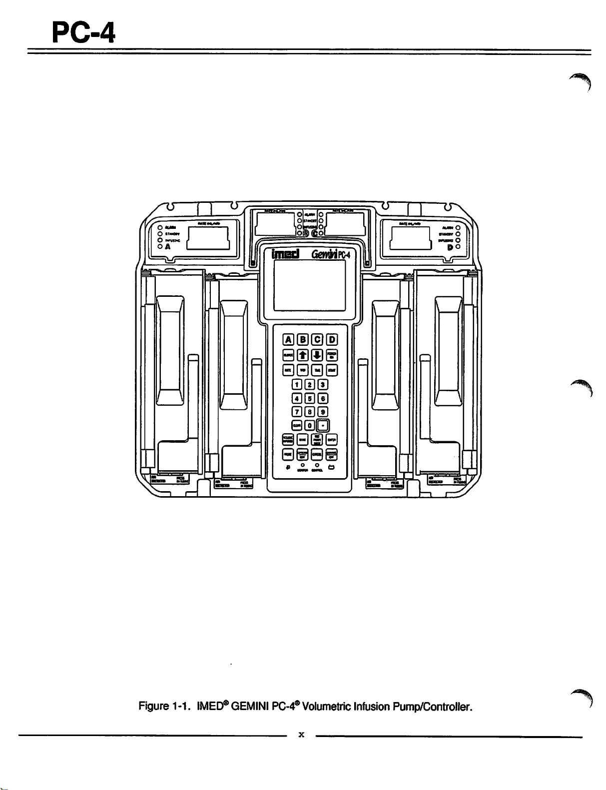
Figure
1-1.
IMED®
GEMINI
PC-4®
Volumetric
Infusion
^%i
Pump/Controller.

PC-4
#*^
SECTION
1.1
INTRODUCTION
This
section
physical description
versionsofthe
includes
IMED®
general
and
GEMINI PC-4® Volumetric Infusion
operating characteristics,
operating specifications for all
Pump/Controller ("PC-4").
1.2
OPERATING
The
GEMINI
infusion pump/controller
intravascular
independent
of
delivery
mode.
peristaltic action.
seriesof12
collapse
pumping
action
cam-actuated
then
segment
produces
a vacuum on
delivering a
accurately
The
four
infusion
continuous
and
channel
techniques
simultaneous
Independent
deliver either a specified volume or
("ALL")
of a solution container.
requires installation
CHARACTERISTICS
Model
PC-4isa
four
usedinthe
drugs
and
fluids.
Each
operationineither
The
pumping
The
peristaltic action is provided by a
mechanism
fingers
release,
in a ripple like action,
of a GEMINI administration
a positive
the
inlet
pressureatthe
sideofthe
flow of infusion solutions reliably,
with a high
configuration
including
primary
and
simultaneous
and
degree
enables
independent
sequential
primary infusions
Useofthe
and
connection ofanEmpty
channel
volumetric
administration of
channel
the
is capable
Pump or Controller
employs linear
that
sequentially
the
set.
outlet
pump, thereby,
of safety.
a variety of
primary,
secondary.
the
entire contents
ALL
soft
setting
Container Detector (ECD) which is availableasan
optional
accessory.
Sequential
secondary
(piggyback)
infusions with independently defined delivery
parameters,
solutions,
Operational control of
control
and
the
instrument. Basic operating instructions
the
right
for both
the
canbeprovided on
and
indicator
Audio
sideofthe
panelonthe
Control
instrument
primary
the
switch
and
secondary
each
channel.
PC-4
is effected through the
front of the instrument
on
the
rearofthe
are
case.
Functional control is
printed on
provided by a 16 bit micro-processor with a stored
program
instrument
subsystem
redundancy
that
includes a
Maintenance
mode
performance,anaudio/visual alarm
to alert
checks
operators
to confirm
to abnormal conditions and
system
accuracy.
to monitor
This
side
can
1 -
DESCRIPTION
1.3
The
Operation) orasa computer controlled device
(Computer Operation). Normal operation includes
Controller
mode. Computer operation includes Monitor
Computer
NORMAL
SYSTEM
The
and
The system configuration
statusofthe
OPERATING
PC-4
canbeoperated
and
Control
OPERATION
OPTIONS
systems
• Adjust
•
Set
•
•
Set
•
To
and
up.
Bold
contrastofthe
the
Time of Day clock
Enable
Anesthesia
up Computer Control
Check
enter
hold
face
System
the
the
type
CONDITIONS
Pump
modes
modes.
option
mode
allows
LCD display
Mode
Configuration
screen
following
selectable
NOTES
Configuration
"OPTIONS/EDIT'
indicates
independently (Normal
plus a Maintenance
the
operatorto:
displays
features:
Setup
mode:
switchatpower
factory
default
• Clock Setup: Military or AM/PM
• Factory Set: Factory default settings
•
Maximum
•
C2
Port:
19200; (Data
xxxx.
•
Aux
•
PCS
Rate:
Max
Baud
300,600,1200,
Frameisset
Port:
No
Port
Mode: P or C or S
usable
rate
2400,4800,
to N81); Serial No.
Channel
1-999
delivery
selection plus mode lock/unlock
• Delayed Start: Enabled or Disabled
• Drug Calc:
•
Multidose:
•
Dose
EnabledorDisabled
Enabled
Display:
FixedorTemp
or
Disabled
• Battery Mode: Disabled Normal High
• Key Audio: Enabled or Disabled
•
Alarm
Audio:
• Switch(over) Audio:
Profile
1,2or3
EnabledorDisabled
the
YES
mL/hr
the
and
current
press
settings.
or NO
9600,
mode
1-1
PC-4
•
Tamper
• Language: English
•
Anesth.
• Comp. Ctrl.:
• Dynamic Press:
•
Press.
•
Vol.
•
S/W
•
MC
•
C2S/N:
•
CRC:
CONTROLLER
In
the
to control
solution.
patient
similar to a gravity infusion.
sensor
bottle
tubing in-line pressure. When in-line
pump input pressure, an occlusion condition exists
and
an alarm is initiated. Actual delivery
directly proportional to container height; increasing
container height raises
reduces
occlusion
from
pressure of <60
FLOWcondition which
pressureisabove
transients
duration or cumulative time required to
volumetric deficiency
in
excess
occlude.
PUMP
In
the
employs a
(69 ±14 kPa) predicated on a nominal container
height of 24 inches (61 cm) and a delivery rate >30
mlJhr. For delivery rates <30
pressure is rate dependent to
of occlusion conditions. Anytransient distal in-line
pressure
occlusion
Mode: Enabled or
Mode:
EnabledorDisabled
Enabled
Enabled
Trend:
Time
Version:
Version:
XXXX/Checksum:
Inf:
XXXX
Enabled
Enabled
SCX.XX.XX.X
X.XX
MODE
CONTROLLER mode,
the
infusion of a specific volume of
The
instrument
side
pressure
measures
and
compares
and
the
hydrostatic
that
and
occlusion
pressure
the
bottle height. Transient
pressure.
toleranceis±12
seconds
stops
the
occlusion threshold.
above
the
occlusion
caused
of30minutes
MODE
PUMP
mode
preset
above
alarm.
occlusion
this limit
will
of operation,
Disabled
or Disabled
or Disabled
or
Disabled
or
Disabled
XXXX
the
PC-4 is programmed
senses
and
responds
container height in a
The
instrument's
pressure
pressure
against distal
pressure
pressure
decreasing
Controller
the
mode
inches
duration
the
threshold
surges
infusion while
in patient
will
produce a LOW
>60
compensate
by periods of Low Flow
cause
pressure
will
the
the
mLThr,
ensure
generate
instrument
instrument
limit
the occlusion
timely detection
a patient
IV
to
manner
pressure
from
the
exceeds
height
(30.5 cm)
the
Pressure
seconds
of 10 ±2 psi
side
is
side
to
for
Software
A
Selectable
occlusion
mmHg (0.5 psi)
Release
(S)
4.10.14.0
pressure
pressuretobe
and
517
and
Subsequent
mode
selected
allows
between
an
25
mmHg (10 psi) in 25
mmHg (0.5 psi) increments. A high occlusion
pressure
will
MAINTENANCE
The
selection
resultinan
maintenance
coupled
increase
MODE
mode
with a slow infusion rate
in
time-to-occlusion.
is intended solely for
use
by biomedical technicians to perform servicing and
maintenance
when
the
maintenance
personnel
test
routines
Maintenance
•
• M/C
•
The
S/C
an
Error Log display with a
COMPUTER
MONITOR
The
Monitor
monitor
performance. Monitor
computer is
Communications
indicatorisilluminated.
COMPUTER
The
Computer Control
once
set
host
computer
actions
and
PCMisconnected
mode
provides biomedical service
accesstothe
and
operating
mode
menu
S/C
board
test
and
board
Press
board
MODE
infusion
test
[off]
to exit
test
and
OPERATION
mode
allows a
status
and
and
modeisenabled
connectedtothe
Data
Port
CONTROL
mode
up, tobecontrolled
installation.
must
never
to
a patient.
closed
loop maintenance
history logs.
includes:
displays
displays
display
sub-menu
100
entry register.
host
computerto
instrument
PC-4 through
and
the
allows an infusion,
and
monitored by a
be
used
includes
when a host
Monitor
The
the
^%
Software
The PC-4, when operating in
Releases
through
3.9.9.4
the
Pump Mode,
locked into a rate-independent (10 psi) occlusion
pressure mode. This mode
increased
time-to-occlusion
will
result in significantly
for
rates
<30
ml_/hr.
can
be
1-2

PC-4
1.4
USER
Instrument control
INTERFACE
and
operation is accomplished
through the 32 keypad controls, the central information
display and
displays. Infusion parameters
the
independent channel information
are
programmed into
the
instrument using the appropriate keypad controls.
Rate
and
Volume-to-be-lnfused (VTBI)
separately for
each
channel.
Rate
secondary infusions (piggyback)
programmable, independent of
parameters, for
Advisory
are
messages
provided to
each
channel. Visual Prompt and
with accompanying audio alerts
assist
operators in setting up
are
the
are
input
and
VTBI
for
also
primary infusion
the
instrument for operation. Infusion completions, alarm
conditions
signaled by both audio
detected
warning. Delayed Start, Multidosing
Calculation
enabled,
menu.
The rear panel of
connection for
Nurse
data
and
software-detected
and
visual alerts; hardware-
malfunctions
infusions,
are
programmed via the Channel Options
each
Call line, a
are
signaledbyan
when
the
PC-4 is configured with an ECD
channel,aconnectortoaccept
standard
RS-232-C
port for interfacing with a
these
host
malfunctions
audio
and
Drug
features
are
communications
computer
are
and
a
an
auxiliaryRS-232-C port for interfacing with ancillary
equipment.
ALARIS
administration
GEMINI
GEMINI
numbersinthe
1.5
The PC-4 instrument
characteristics:
Medical
Systems
sets
are
required for
GEMINI
family of Infusion Pump/Controllers.
Series
PHYSICAL
of instruments
2000
number
DESCRIPTION
has
the
uses
series.
following physical
Series
use
sets
disposable
with
the
The
with part
FRONT
The
aluminum shell which
pumping
pumping
beam), Air-in-line
keypad,
display circuit
and
REAR
The
cast
internally:
oscillator, power supply CCA
harness
supports
storage, battery
retention
the
model.
1.6
The
Pump/Controller
time a
Table
1.7
The
subordinated
Performance
Tables
CASE
front
case
chamber
mechanisms,
the
motor
control
CASE
rear
case
consists
channel
card
assembly
ofaninvestment-cast
houses
access
pressure
and
Slide clamp detectors,
and
assemblies
CCAs.
and
doors, the peristaltic
transducers (strain
central displays, the
(CCAs), logic CCA
consists of an investment-
supports:
aluminum shell which mounts and supports
the
transformer
assembly.
the
pole
access
strap,
power
The
clamp, power entry module, ECD
harness
exterior of
assembly, audio
and
communication
the
with covers, power cord
cord retention bracket
equipotential grounding point on the 220V
PRODUCT
initial
numberofchanges
1-1 for
OPERATING
PC-4
HISTORY
releaseofthe
wasinDecember
product
Operating
history.
SPECIFICATIONS
Specifications
GEMINI PC-4® Infusion
1992. Since that
have
occurred. Refer to
are
into Operating Requirements and
1-2
Specifications
and
1-3 respectively. Tables 1-2 and 1-3
which
are
respectively.
1.8
ACCESSORIES
the
rear
case
and
delineated in
Height: 12 inches (30.5 cm)
Width: 14.75 inches (37.5 cm) with pole clamp
Depth: 7.5 inches (19.1 cm) with pole clamp
*22
Weight:
pounds (10 kg) including power cord
The PC-4 instrument consists of two major
assemblies:
the
front
and
rear
cases.
1-3
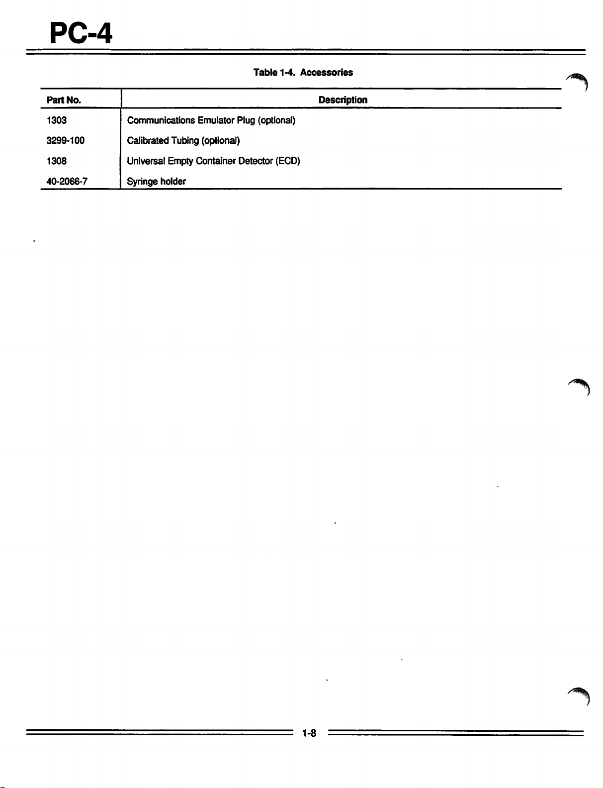
The
accessories
are
listedinTable
approved for
1-4.
use
withthe PC-4
PC-4
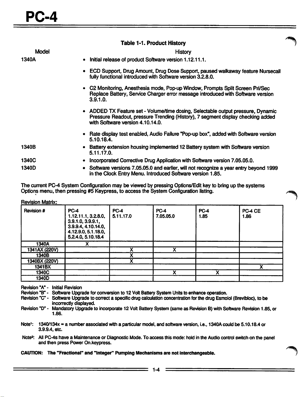
Model
1340A
1340B
1340C
1340D
The
current PC-4
Options menu,
• Initial
• ECD Support, Drug Amount, Drug Dose Support,
fullyfunctional introduced with Software version 3.2.8.0.
• C2 Monitoring, Anesthesia mode, Pop-up Window, Prompts Split
Replace
3.9.1.0.
• ADDED TX Feature
Pressure
with
•
Rate
5.10.18.4.
• Battery
5.11.17.0.
• Incorporated Corrective Drug Application with Software version 7.05.05.0.
• Software versions 7.05.05.0
in
the
System
then
Configuration may be viewed by pressing Options/Edit key to bring up
pressing#5Keypress, to
Table
1-1.
Product
History
History
release
of product Software version 1.12.11.1.
paused
Battery, Service Charger error
set
- Volume/time dosing, Selectable output pressure, Dynamic
Readout, pressure Trending (History),7
Software
display
version
test
extension
4.10.14.0.
enabled,
Audio Failure "Pop-up box",
housing implemented 12 Battery
and
earlier,
message
introduced with Software version
segment
system
will
not recognize a year entry beyond 1999
Clock Entry Menu. Introduced Software version 1.85.
access
the
System
Configuration listing.
walkaway feature Nursecall
Screen
display checking
added
with Software version
Pri/Sec
added
with Software version
the
systems
Revision
Revision
Revision
Revision "B"- Software Upgrade for conversion to 12 Volt Battery System Units to
Matrix:
#
1340A
1341AX(220V)
1340B
1340BX(220V)
1341BX
1340C
1340D
"A" -
Initial
PC-4
1.12.11.1,3.2.8.0,
3.9.1.0,3.9.9.1,
3.9.9.4,4.10.14.0,
4.12.9.0,5.1.18.0,
5.2.4.0,5.10.18.4
X
Revision
PCM
5.11.17.0
PCM
7.05.05.0
X X
X
X
PC-4
1.85
X
enhance
X
operation.
PC-4CE
1.86
Revision"C"- Software Upgrade to correct a specific drug calculation concentration for the drug Esmolol (Brevibloc),to
incorrectly displayed.
Revision "D"- Mandatory
1.86.
Note1: 1340/134x = a
Note8:
3.9.9.4,
All
and
PC-4s
then
etc.
have
press
Upgrade
number
to incorporate 12 Volt Battery System
associated
with a particular model,
a Maintenance or Diagnostic Mode. To
Power
On.keypress.
and
access
(sameasRevision B) with Software Revision 1.85, or
software version, i.e., 1340A couldbe5.10.18.4 or
this mode: hold in the Audiocontrol switch on the panel
X
be
CAUTION:
The
"Fractional"
and
"Integer"
Pumping
Mechanisms
1-4
are
not
interchangeable.
^^
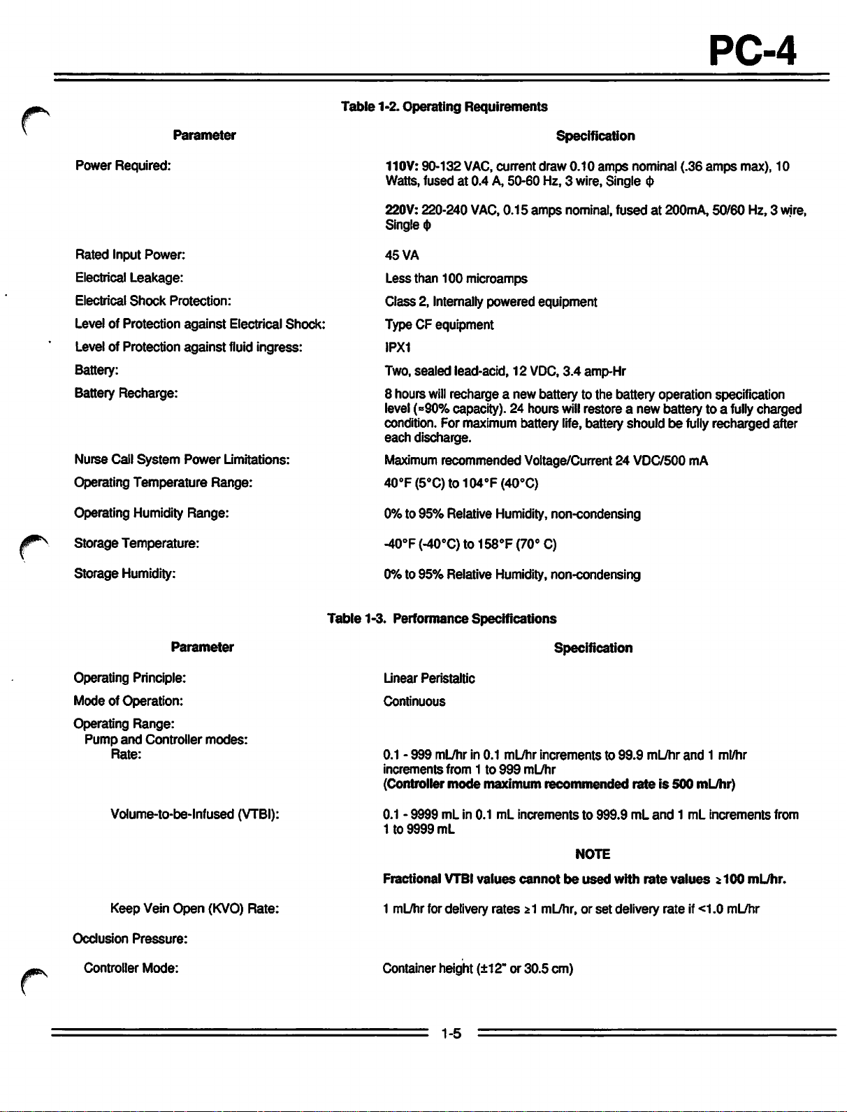
Power
Required:
Parameter
Table
1-2. Operating
Requirements
Specification
110V: 90-132
VAC,
current draw 0.10
amps
Watts, fused at 0.4 A, 50-60 Hz, 3 wire, Single
nominal (.36
<J>
PC-4
amps
max), 10
Rated
Input
Power:
Electrical
Electrical
Level of Protection
Leakage:
Shock
Protection:
against
Electrical Shock:
Level of Protection against fluid ingress:
Battery:
Battery
Nurse Call
Operating
Recharge:
System
Temperature
Power
Limitations:
Range:
Operating Humidity Range:
Storage
Storage
Temperature:
Humidity:
220V: 220-240 VAC, 0.15
Single
<t>
45
VA
amps
nominal,
fusedat200mA,
Less than 100 microamps
Class 2, Internally powered equipment
Type CF equipment
IPX1
Two,sealed lead-acid, 12
8 hours
will
recharge a new battery to the battery operation specification
level(-90% capacity). 24 hours
VDC,
3.4
amp-Hr
will
restore a new battery to a
condition. For maximum battery life, battery should be
each
discharge.
Maximum
recommended Voltage/Current 24 VDC/500 mA
40oF(5°C)to104oF(40°C)
0% to 95% Relative Humidity, non-condensing
-40°F (-40°C) to 158°F (70° C)
0% to 95% Relative Humidity, non-condensing
50/60
fully
fully
recharged after
Hz, 3 wire,
charged
Parameter
Operating Principle:
Mode of Operation:
Operating
Pump
and
Rate:
Range:
Controller
Volume-to-be-lnfused
Keep
Vein
Open
Occlusion
Controller
Pressure:
Mode:
modes:
(KVO)
(VTBI):
Rate:
Table
1-3. Performance
Container height (±12" or 30.5 cm)
Specifications
Specification
Linear
Peristaltic
Continuous
0.1 -
999
mL/hrin0.1
increments
(Controller
0.1 -
1to9999
Fractional
from1to
mode
9999mLin 0.1mLincrementsto999.9
mL
VTBI
1 mLmrfor delivery
ml_/hr
999
maximum
values
rates
incrementsto99.9
mL/hr
recommended
cannot
21 mL/hr, or
be
NOTE
used
set
rateis500
mL
with
rate
delivery
mL/hr
and1ml/hr
and1mL
values
rate
mL/hr)
increments
2100
mL/hr.
if<1.0 mL/hr
from
1-5
PC-4
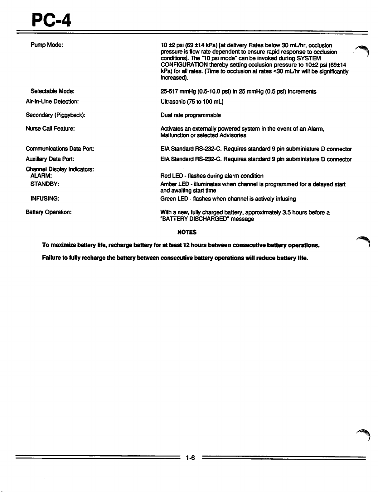
Pump
Mode:
10 ±2 psi (69 ±14 kPa) [at delivery
pressure is flow rate
dependenttoensure
conditions]. The "10 psi mode"
CONFIGURATION
thereby setting occlusion
Rates
below30mL/hr, occlusion
rapid
response
can
be invoked during SYSTEM
pressure
kPa) for all rates. (Timeto occlusion at rates <30 mL/hr
increased).
to occlusion
to 10±2 psi (69±14
will
be significantly
Selectable
Air-ln-Line
Mode:
Detection:
Secondary (Piggyback):
Nurse
Call
Feature:
Communications
Auxiliary
Data
Port:
Data
Port:
Channel Display Indicators:
ALARM:
STANDBY:
INFUSING:
Battery Operation:
To
maximize
battery life, recharge battery for at least 12
Failure to fully recharge
the
battery
between
25-517 mmHg (0.5-10.0 psi) in 25 mmHg (0.5 psi) increments
Ultrasonic (75 to
100
mL)
Dual rate programmable
Activates an externally
Malfunctionorselected
EIAStandard RS-232-C. Requires
EIAStandard RS-232-C. Requires
Red LED-
flashes
Amber LED- illuminates
and
awaiting
start
Green LED- flashes when
Witha new, fully
"BATTERY
DISCHARGED"
NOTES
hours
consecutive
battery
during
time
charged
between
operations
powered
Advisories
systeminthe
standard
standard
alarm
condition
when
channel is
channel
is actively infusing
battery, approximately
message
consecutive
will
reduce
eventofan
Alarm,
9 pin subminiature D connector
9 pin subminiature D connector
programmed
battery
battery
for a
3.5
hours
operations.
life.
before a
delayed
start
/^Hk
1-6
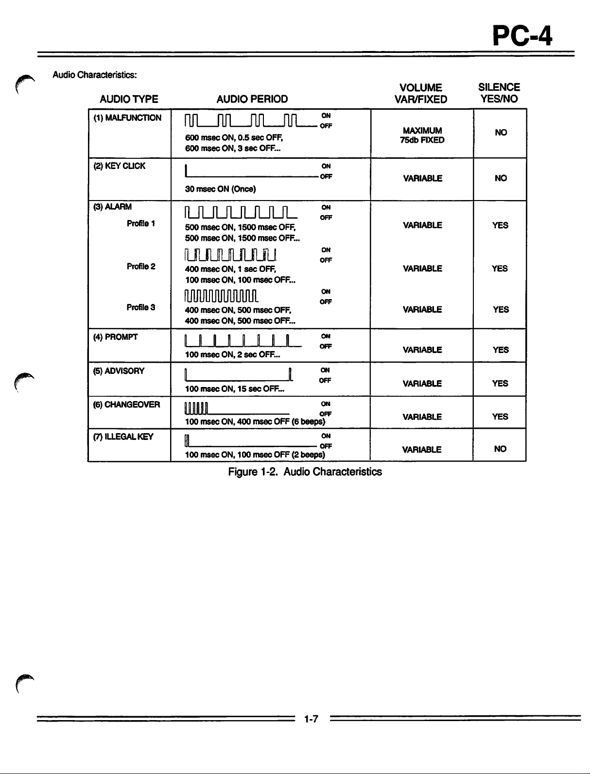
Audio
Characteristics:
AUDIO
(1) MALFUNCTION
TYPE
600
600
msec
msec
AUDIO
ON,
ON,3sec
0.5
PERIOD
sec
OFF,
OFF...
PC-4
VOLUME
VAR/FIXED
ON
—
OFF
MAXIMUM
75db
FIXED
SILENCE
YES/NO
NO
(2) KEY CLICK
(3) ALARM
Profile
1
Profile
2
Profile
3
(4) PROMPT
(5) ADVISORY
(6) CHANGEOVER
(7) ILLEGAL KEY
l
1
30
msec
ON (Once)
UULfULOJL
500
msec
ON,
1500
msec
OFF,
500
msec
ON,
1500
msec
OFF...
uimmjuu
400
msec
100
msec
ON,1sec
ON,
100
OFF,
msec
OFF...
aiMuuuum
400
msec
ON,
500
msec
OFF,
400
msec
ON,
500
msec
OFF...
I I I I » I I I
100
msec
ON,2sec
I I
100
msec
ON,15sec
ggmgg
100
msec
ON,
ll
100
msec
ON,
400
100
OFF...
OFF...
msec
msec
OFF (6 be
OFF (2 be
teps)
—
«ps)
ON
OFF
ON
OFF
ON
OFF
ON
OFF
ON
OFF
ON
OFF
ON
OFF
ON
OFF
VARIABLE
VARIABLE
VARIABLE
VARIABLE
VARIABLE
VARIABLE
VARIABLE
VARIABLE
NO
YES
YES
YES
YES
YES
YES
NO
4^*
Figure 1-2. Audio Characteristics
1-7
PC-4
Table
1-4.
Accessories
Part
No.
1303
3299-100
1308
40-2066-7
Communications
Emulator
Plug (optional)
Calibrated Tubing (optional)
Universal Empty Container Detector (ECD)
Syringe holder
Description
1-8
/-^^.
#*N
PC-4
SECTION
2.1
INTRODUCTION
This procedure contains information relative to
initial inspection
IMED®
GEMINI PC-4® Volumetric Infusion
Pump/ControllerfPC^").
and
pre-operational
These
checkoutofthe
procedures
mechanical inspection, electrical inspection,
operational battery
to
ensure
has
2.2
The
and
the
that
not
been
PRE-OPERATIONAL
INSPECTION
PC-4
has
quality
factory.
assurance
The
designed to protect
under
normal shipping conditions;
internal physical and/or electronic
could
have
occurred without leaving a visible
signature. Therefore, it is
charge
the
instrument
damaged
undergone
shipping
the
and
a performance
operates
during
MECHANICAL
shipmentorstorage.
properly
thorough production control
testing prior to shipment from
container
instrument
has
been
against
nevertheless,
component
recommended
damage
that
2 -
the
include a
pre
check
and
damage
the
following inspection procedurebeperformed upon
receipt of the instrument at the
1. Carefully
container.
in
the
the
2. Inspect
holes,
damaged
screws.
3. Inspect
remove
(Save
event
the
factory for
the
exterior
cracks,
controls, missing
the
green
the
the
instrument
service
case,
scratches,
tinted windows covering
channel information displays
covering
4. Ensure
flush with
5.
Check
operation
the
the
the
LCDfor
pumping
the
caseatthe
door
and
flush fitwith
handle/cam
user's
PC-4
from
facility.
the
shipping
shipping material for
must
be
returned
or repair).
front
and
rear, for
spalling, broken
components
and
the
screen
scratches
chamber
or cracks.
access
top, bottom,
locks
for
door
when
doors fit
and
ease
latched.
reuse
or
and/or
the
sides.
of
PREPARATION
to
FOR
USE
6. Inspect the pumping mechanism
damage and to
to
the
front
7.
Inspect
the
recesses
8. Install an approved
GEMINIadministration
assembly
ensure
case.
Air-in-line
for
damage
seats
they
sensorsand
or obstructions.
ALARIS
settoensure
correctly
and
seals
for
are
properly attached
Flo-Stop®
Medical Systems
the
Flo-Stop
the
door closes and
latches properly.
9. Inspect the power cord for
or
deformed
10. Exercise
freedom
connector.
the
pole clamp mechanism to
of
movement.
damage,
bent prongs
ensure
11. Checkthe Equipotential grounding point for
damage
In
the
shipping
immediately.Donot
instrumenttothe
agent
Medical (refertoSales
for a listofphone
return
liability for repair
2.3
OPERATIONAL
Priorto the first operational
routine maintenance or servicing of
and
security.
event
the
PC-4
damage,
notify
factory
has
authorized repairs.
numbers) for authorization to
the
instrument
costs.
PERFORMANCE
NOTE
shows
the
return a
before
and
for repair
use
evidence
carrier's
damaged
the
Contact
Service
regardless
and
following any
the
of
agent
carrier's
ALARIS
Offices
CHECK
PC-4, it is
ftjgfi
page
of
strongly recommended that an abbreviated
operational performance check be performed. The
operational performance check consists of two
phases; a Pre-operational Electrical Inspection to
check
the
electrical integrity of
the
instrument for
compliancewithregulatory agency requirements and
an operational performance test to verify
pump/controller performance.
2-1
PC-4
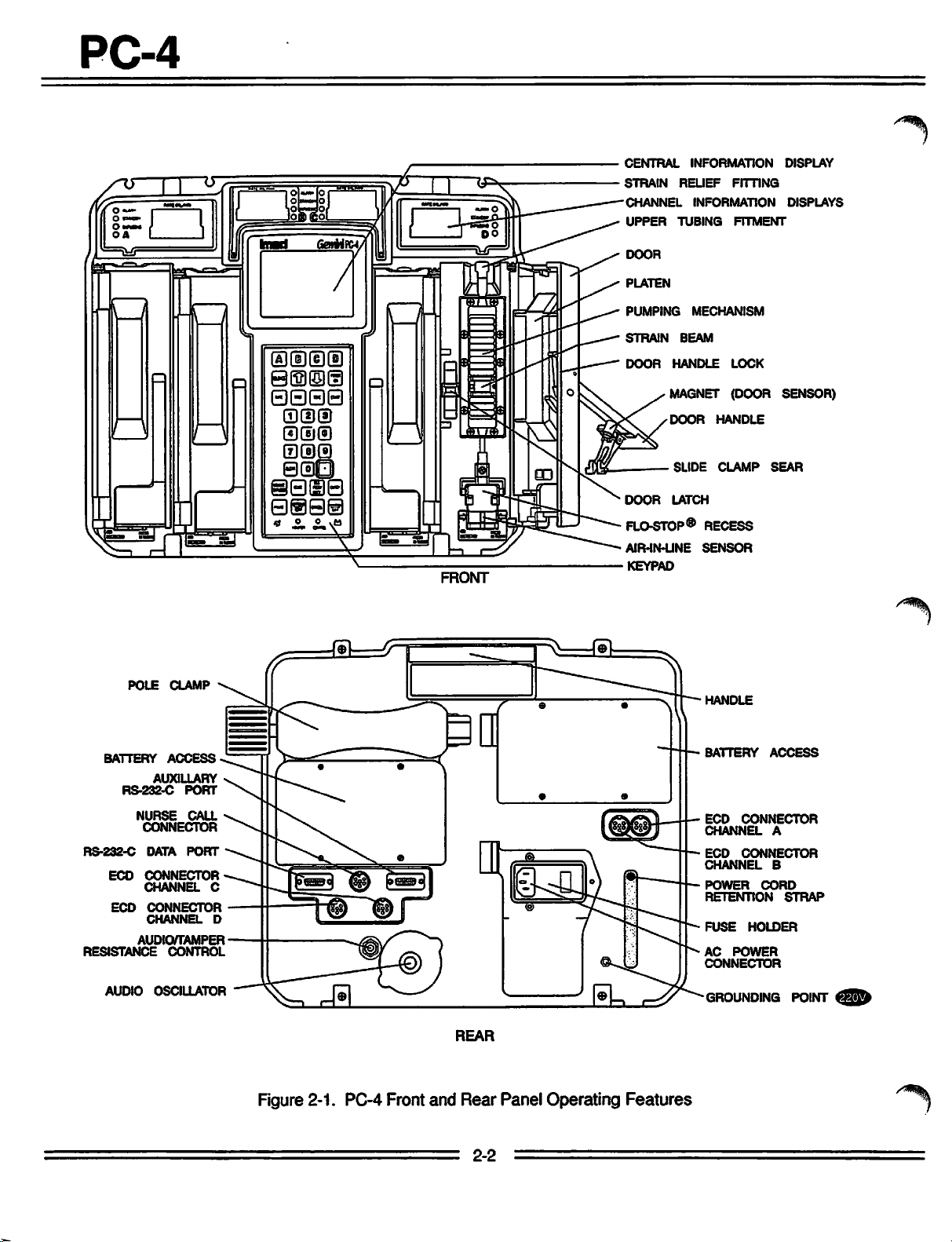
FRONT
CENTRAL
STRAIN
CHANNEL
UPPER
DOOR
PLATEN
PUMPING
STRAIN
DOOR
INFORMATION
RELIEF
INFORMATION
TUBING
MECHANISM
BEAM
HANDLE
FITTING
FITMENT
LOCK
MAGNET (DOOR
DOOR
DOOR
SLIDE
LATCH
HANDLE
CLAMP
FLO-STOP® RECESS
AIR-IN-LINE
KEYPAD
SENSOR
DISPLAY
DISPLAYS
SENSOR)
SEAR
POLE
BATTERY
RS-232-C
RS-232-C
ECD
ECD
RESISTANCE
AUDIO
CLAMP
ACCESS
AUXILIARY
PORT
NURSE
AUDIO/TAMPER
CALL
CONNECTOR
DATA
PORT
CONNECTOR
CHANNEL
CONNECTOR
CHANNEL
CONTROL
OSCILLATOR
HANDLE
BATTERY
ECD
CHANNEL
ECD
CHANNEL
C
D
POWER
RETENTION
FUSE
AC
CONNECTOR
GROUNDING
ACCESS
CONNECTOR
A
CONNECTOR
B
CORD
HOLDER
POWER
STRAP
POINT
<3^h
REAR
Figure2-1. PC-4 Front and Rear Panel Operating Features
2-2
PC-4
2.3.1
Pre-operational
The
batteries
completion of
assurance
time could
a pre-operational battery
Connect
and
allow
2.3.2
Pre-operational
The
pre-operational electrical inspection includes
electrical
Someofthese
Safeguards
be
employed
should
personnel.
2.3.2.1 Electrical
Perform an electrical
compliance with Underwriters Laboratories (UL)
for Patient
Association (CSA)
Class
2G Equipment or IEC
aretobe
2.3.2.2
Perform an electrical ground
measurementincompliance
Care
Equipment or CSA
Risk
Class
impedance
cord plug
should
2.3.3
Abbreviated
Test
The following operational performance
designed to
indicators
mechanisms
are
in a fully
the
post
inspection. However,
elapse
the
AC power cord to a suitable AC outlet
the
battery to
leakage
onlybeperformed
Care
less
Electrical
2G EquipmentorIEC 601-1.
and
not
exceed
are
test
tests
for
when
EquipmentorCanadian
than
between
the
grounding point on
ensure
functioning properly
are
in working order.
Check
manufacturing quality
between
chargeisrecommended.
charge
Electrical
andaground
CAUTION
are
personnel
conducting
Leakage
leakage
Standard
100
microamperes.
Ground
Standard
the
grounding pin on
100
milliohms.
Operational
that
the
Battery
charged
since
manufacture
for 24 hours.
inherently
and
by
Test
current
C22.2
601-1.
Test
impedance
with UL
PC-4's
Charge
condition upon
considerable
and
first
Inspection
continuity
hazardous.
property
such
qualified
measurement
No.
Leakage
544
C22.2 No.
the
Performance
controls
and
should
tests.
Standards
125
for Risk
currents
for Patient
125
The
the
rear
test
is
and
all pumping
power
case
use,
an
check.
Tests
544
for
in
2. Four (4)IVSolution Containers.
3.
Standard
4.
10
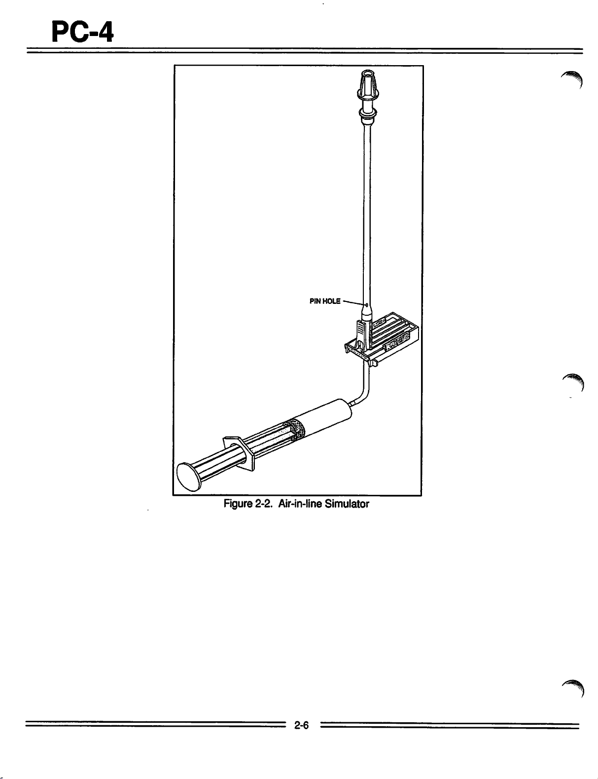
5. Open-ended
2-2).
6. Pressure
capability.
7. Safety Analyzer - Dynatech-Nevada Model 231D
or equivalent.
8. Air-in-linesimulator
2.3.3.2
The
following
presented
qualitative
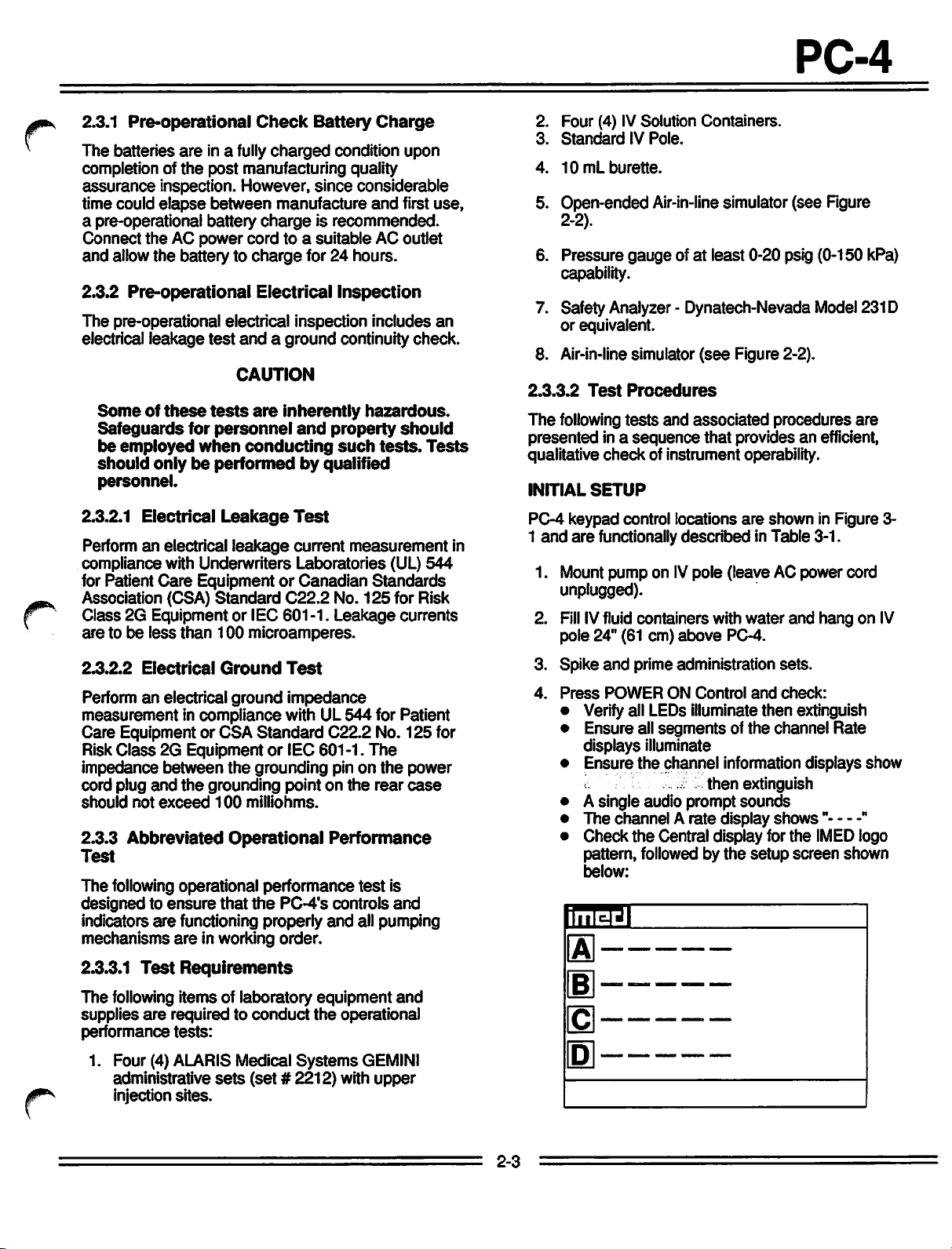
INITIAL
PC-4 keypad control locations
1
and
are
1. Mount pump on
unplugged).
Fill
2.
pole 24" (61 cm)
3. Spike
4.
Press
• Verifyall LEDs illuminate then extinguish
• Ensure all
•
• A single audio prompt
•
•
IV
Pole.
mL
burette.
Air-in-line
gaugeofat
Test
Procedures
tests
and
in a
sequence
check
of instrument operability.
SETUP
functionallydescribed inTable 3-1.
IV
lIll
IVfluid containers with
lIII
and
prime administration
IIIl
POWER
displays illuminate
Ensure
The
channel A
Check
pattern, followed by
below:
ON
segmentsofthe
the
channel information displays show
the
Central display for
simulator (see Figure
least 0-20 psig (0-150 kPa)
(see
Figure 2-2).
associated
that
pole (leave AC power cord
above
Control
IlII
PC-4.
Illl
.;
then
rate
display
the
procedures
provides an efficient,
are
shown in Figure 3-
water
and
sets.
and
check:
channel Rate
extinguish
sounds
shows"
the
setup
screen
are
hang on
IMED
shown
"
logo
HnltNl
IV
2.3.3.1
The
supplies
performance
1. Four (4) ALARIS Medical
Test
Requirements
following items of laboratory
are
requiredtoconduct
tests:
administrative
injection
sites.
sets
(set#2212)
equipment
the
operational
Systems
with
and
GEMINI
upper
2-3
PC-4
7. Press
8.
Hi
then
press
Use
the
system
available
toselectthe
Q
to
(J
Q
configuration display to determine options
and
the
select
Systems
System
Options
Configuration.
controlstotoggle
statusofeach
option.
through
9. Press 0 twiceto returntothe Setup screen
shown
CHARGING
1.
Connect
and
•
2. Unplug AC
and
• AC
3. Press
• Battery Operation indicator - flashes.
4.
Reconnect
•
• Battery Operation indicator - extinguishes.
PUMP
The
channelAand
channels.
1.
Open
•
above.
INDICATION
AC Power cord to an AC power source
check:
AC
Power
check:
Power
Up;
AC
Power
MODE
following
the
The
mechanism
#11 finger in fully extended.
Indicator-Illuminates.
Power
following
AC
TEST
channelAaccess
pumping
cord from
Indicator - extinguishes.
instrument
Power
indicator-illuminates
procedures
cordtothe the
NOTE
are
applicabletoall PC-4
mechanism
rotates
to a position
the
AC power
initialization:
are
described
door
and
"homes", i.e. pump
instrument.
check:
where
menu,
the
source
for
the
Fil
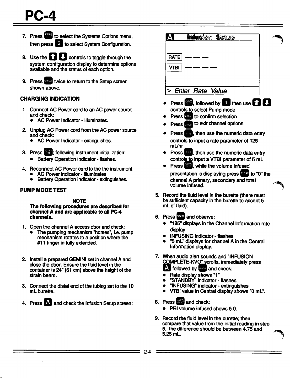
RATE
VTBI
>
•
Press
controls to
•
Press
• PressBB to
•
Press
controls to input a rate
mL/hr
• Press
controlsto input a
•
Press
Enter
@,
SBt0
^9,
^p,
^p,
Omftuigtoira
Rate
followedbyQ
select
Pump
confirm
exit
channel
then
use
then use the numericdata entry
while
the
presentationisdisplaying
channel A primary,
volume
5. Record
be sufficient capacity in
mLof fluid).
6. Press ^ and observe:
• "125" displays in
display
•
INFUSING
• "5 mL"displays for
Information display.
infused.
the
fluid level in
the
indicator-flashes
Scaup
Value
then
use
Q Q
mode
selection
options
the
numeric
parameterof125
VTBI
parameter
volume
press
secondary
the
burette (there must
the
burette to
Channel Information rate
channel
data
infused
^pto"0"
and
A in
the
entry
of 5 mL
total
accept
Central
the
5
2. Install a prepared
close
the
door.
container is 24" (61 cm) above
strain
beam.
3.
4.
Connect
mL
Press
burette.
Q
the
and
Ensure
distal
check
GEMINI
endofthe
the
the
Infusion
set
in channel A and
fluid
levelinthe
the
height of the
tubing
settothe
Setup
10
screen:
2-4
7.
When
audio
alert
sounds
COMPLETE-KVO"scrolls. immediately
Q
followedbyQ
• Rate display
•
"STANDBY"
• "INFUSING" indicator - extinguishes
VTBI
•
8.
PressHand
•
9.
Record
compare that value from
5.
The
5.25
value in Central display
PRI
volume
the
difference shouldbebetween
mL
shows
indicator-flashes
check:
infused
fluid level in
and
"1"
shows
the
and
"INFUSION
check:
burette;
the
initial
press
shows"0mL".
5.0.
then
reading in step
4.75
and
.-^
^
10.
Repeat
D.
steps
1 through 9 for
channels
B, C
and
7. Press
Mode
PC-4
^p
twiceto returnto the Maintenance
screen.
f*^
OUTPUT
1. Connect
2.
3. Press
PRESSURE
the
distal
pressure
Reset
• Pumping
•
•
•
gauge.
the
channelAVTBIto25
^p
and observe:
mechanism
Audio
Alarm
ALARM
"OCCLUDED-PATIENT
continuously
indicator-flashes
TEST
end
sounds
• Central Information displays
for
4. Record
sheet
be
between8and
5. Press
channel
pressure
immediately following alarm (reading must
^p
A.
gauge
12 psi [55.2
to silence the audio, then press [•
followedby0.
6. Turn
7.
8.
MAXIMUM
1.
2.
3.
the
stopcock on
relieve
Repeat
D.
When
orasappropriate,
channel.
Initialize
Press
Displays.
Press
the
pressure.
steps1through
all
channels
PRESSURE
instrument
|9
to
select
Q
to
select
then
have
in
M/C
maximum
of the tubing
mL.
stops
SIDE"
shows
reading on
and
the
pressure
7 for
channels
been
tested,
^ptopower
TEST
the
Maintenance
Board
Tests
pressure
set
scrolls
the
82.8
gauge
press
down
and
to the
ALARM
data
kPa]).
to
B, C
and
the
Mode.
test.
8. Turn
9.
10.
AIRINLINE
1.
2. Install
3.
4. Use
5.
6.
7.
8. Verify
stopcockonthe
the
pressure.
Repeat
D.
Press3Qtwice,
instrument.
Open
administration
simulator into
mechanism,
detector.
Push
poweronin Alarm mode).
level to
Close
Set
press
Use
level
AIL
• Pumping
• Operating LED indicator
•
•
•
• Central Information display
9.
steps
1 through 7 for
thenQto
TEST
the
channel A
set.
the
pumping
the
then
the
slide
clampin(the
the
AILsimulator plunger to
the
top of
the
door.
therate
to
125
Q.
the
AILsimulator plunger to
below
the
AIL
that
within 2
alarm:
stops
Alarm
audio
sounds
Alarm
LED
flashes
Channel
LINE"
for appropriate channel.
Select
Information display scrolls "AIR IN
the
test
pressure
gauge
channels
power
access
segmentofthe
channel A pumping
press
the
mL/hr
detector.
seconds
channel
door
and
Air-in-line
the
tubing into
instrument will
raise
slide clamp fitment.
and
VTBIto50
draw
the
PC-4
stops
flashing
shows
and
press
to relieve
B, C
down
the
remove
the
AIL
the
fluid
mL
the
fluid
goes
"ALARM"
^9
to
and
the
auto
and
into
4.
Press
Eltoselect
5. Press
6. Record
^p
least30seconds
stabilizes.
Resultant
kPa).
channel
A.
and allowthe pump to operate forat
and
the
pressure
highest
wait until
pressure
must
reading
be
*17
the
peak
obtained.
psi
(117.3
pressure
powerdownor
for
test.
Iffurther quantitative testing is required to comply with
hospital protocol for acceptance/qualification of
equipment, refer to
Test
Procedures
manual.
2-5
IB
to set up another channel
the
Comprehensive Operational
describedinSection7of
this
new
PC-4
Figure 2-2. Air-in-line Simulator
2-6
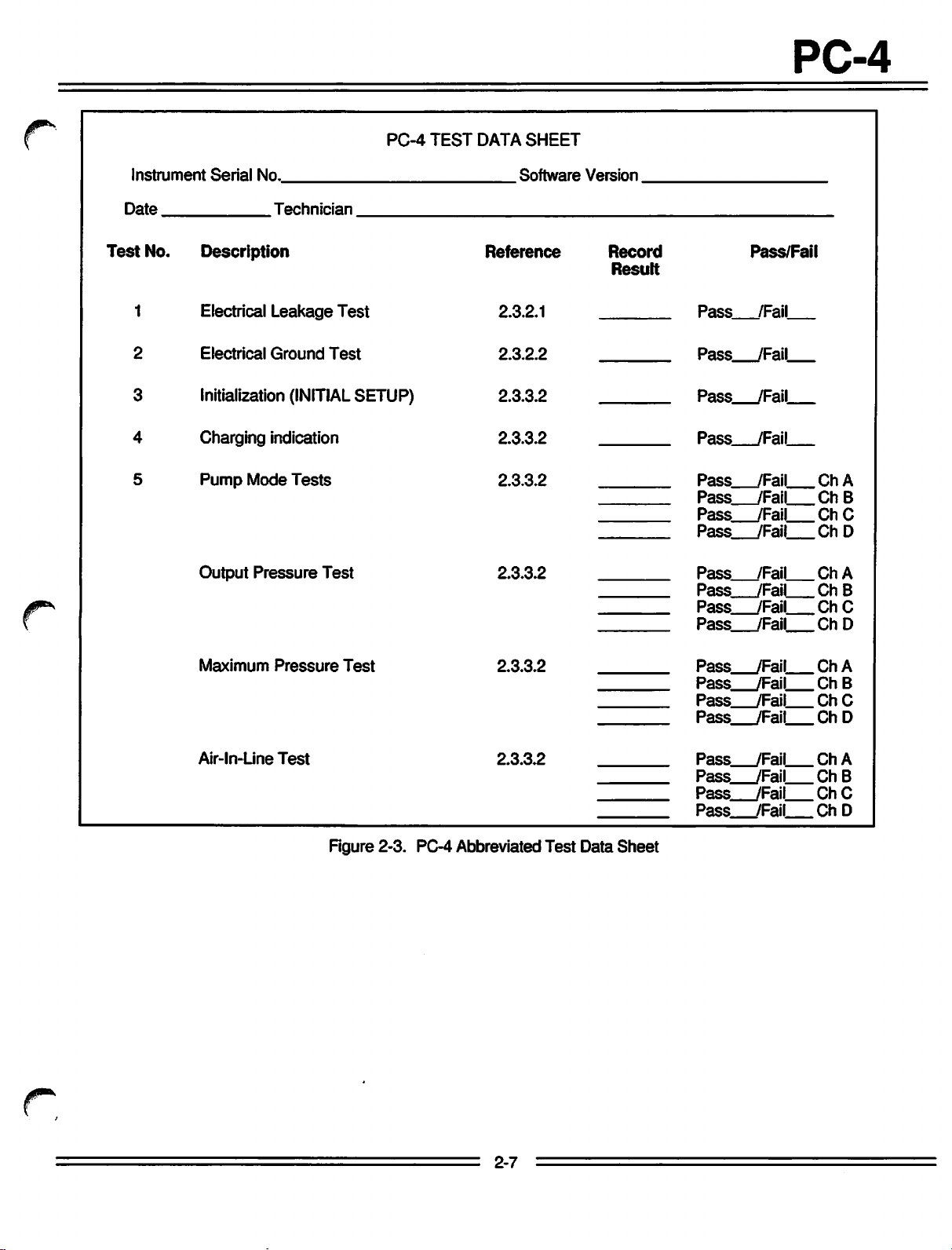
PC-4
TEST
DATA
PC-4
SHEET
Test
Instruir
Date
No.
1
2
3
4
5
ent
Serial
No.
Technician
Description
Electrical
Electrical
Initialization
Leakage
Ground
(INITIAL
Charging indication
Pump
Mode
Tests
Output
Pressure
Test
Test
Test
SETUP)
Software
Reference
2.3.2.1
2.3.2.2
2.3.3.2
2.3.3.2
2.3.3.2
2.3.3.2
Version
Record
Result
Pass
Pass_
Pass_
Pass_
Pass
Pass
Pass_
Pass
Pass
Pass
Pass
Pass
Pass/Fail
/Fail
.JFail
_JFail
_/Fail
/Fail
/Fail
/Fail
/Fail
/Fail
/Fail
/Fail
/Fail
Ch
Ch
Ch
Ch
Ch
Ch
Ch
Ch
A
B
C
D
A
B
C
D
Maximum
Air-ln-Line
Pressure
Test
Test
2.3.3.2
2.3.3.2
Figure 2-3. PC-4 Abbreviated
Test
Data
Sheet
Pass_
Pass_
Pass_
Pass_
Pass_
Pass
Pass_
Pass_
_JFail
.JFail
_JFail
_/Fail
_JFail
/Fail
_JFail
/Fail
Ch
Ch
Ch
ChD
Ch
Ch
Ch
Ch
A
B
C
A
B
C
D
2-7
PC-4
SECTION
3.1
INTRODUCTION
This section describes the recommended
procedures foroperation ofthe
(PC-4®)
software
procedures
releases,
with
provide
Volumetric
release
for instruments with earlier software
Infusion
5.10.18.4. For operating
referto the Operator's Manual provided
the
instrument.
maintenance
The
informationisintended
technicians with a
IMED®
GEMINI
Pump/Controller
basic
with
to
understanding of instrument operation includingthe
audio alerts
and
visual displays.
NOTE
Although
testedtoexacting
itisnot
roleofmedical
supervision
userisurgedtoexercise
vigilanceinthe
PC-4.
the
PC-4isbuilt
specifications,
intendedtoreplace
personnelinthe
ofIVinfusions.
utilizationofthe
and
the
The
3 -
OPERATION
3.2
The
CONTROLS
controls
and
AND
INDICATORS
indicators
usedtoset
operate the PC-4 are illustrated in Figure
the
functional
descriptionslisted inTable3-1.
up and
3-1
with
3-1
PC-4
CHANNEL
DISPLAY
INFORMATION
RATE
(ML/HR)
u
11
u n
u O
u.o
IMililMi]
TYPICAL
imecl
EH3E
B
CENTRAL
O ALARM O
O
STANDBYO
.O
INFUSING
|0B
CHANNEL
Of
CO^
G0WIPC-4
INFORMATION
RATE (ML/HR)
u u u o
uuu.u
DISPLAY
i i
DISPLAY
RATE
DISPLAY
CURRENT
(ONLY ACTIVE FOR TIME-
BASED OPERATIONS)
STATUS
DATA
PROMPT
BAR
ENTRY
TIME
UNE
WINDOW
WINDOW
WINDOW
/^^%\
A B C D
SIENCE
* *
•\ t \ r
VTBJ
TIME
H
BBB
BBB
BBB
BSD
VOLUME
(KFUSED
PAUSE
* ° ° a
DOSE
OPTIONS
HOT
MONnOR CONTROL
SEC
PIGGYj]ENTER
BACK
CANCEL
POWER
ON
START
CHANNEL
OFF
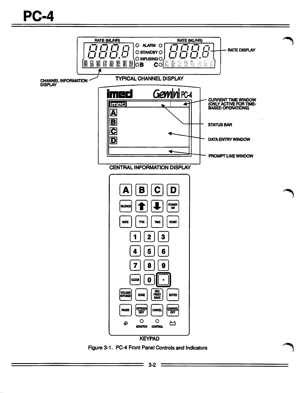
Figure
3-1.
PC-4
Front
KEYPAD
Panel
3-2
Controls
and
Indicators

PC-4
Table
Channel Information (Alarm/Status) Display - Channel
malfunctions.
section of this manual for specific
(RefertoCHANNEL,
3-1.
DESCRIPTION
CENTRAL
response
OF
INFORMATION
procedures.)
CONTROLS
A,B,C,or
Ddisplays various advisories, alarms, and
DISPLAY
RATEdisplay - Channel A, B, C, or D- displays primaryand secondary rate
Channel
infusion
Select
A,B,C, or Dindicators- when illuminated, indicatethat the correspondingchannel is selected for
parameter
entry
and
infusion
setup.
Standby indicator - illuminates whenthe channel is programmed fora
Alarm indicator - illuminates when
Infusing indicator - flashes when the channel is actively infusing.
Central Information Display - displays
parameters during operation ofthe instrument.
confirmation
after the
Keypad
Elto13
M
and displayof prompts, advisories and alarm conditions.The display backlight
last
keypress.
controls-when
*^
and
infusion
pressed
setup.
the
channel is in an alarm or infusion complete condition.
VTBI
(volume-to-be-infused), current time ofday and other operating
During
once,
set
selects
up procedures, providesdisplayfordata entry,
the
corresponding
AND
AND
future
INDICATORS
ALARM
RESPONSE
infusion
start
time.
channel
for
parameters.
will
extinguish 2 minutes
infusion
parameter
PROCEDURES
editing,
entry
r^^
til
**t0
|B|
when
pressed
"PRESS
or
when pressed, allows the rate infusion parameter on the selected channel to be changed using the
appropriate
when pressed, allows
data
when
only that channel
to power off
off
entry controls.
R data entrycontrols - whenpressed,
**
when
when
when
press of the Volume Infused control, clears the total, primaryand secondary volume infuseddisplaysfor
the
operating
pressed,
pressed,
pressed,
selected
duringaninfusion,
START' visual
pressed,
the
PC-4.
data
entry controls.
and
stops
had
the
PC-4. When
the
VTBI
audio prompt begins.)
parameters.
insertsadecimal
allows entry of time-related
clears
channel.
the
currently
the
infusion for
the
infusion for
been
infusing, powers off
pressed
parameter on the selected channel to be changed using the appropriate
pointinnumeric
data
selected
the
selected
the
selected
during a software-detected system malfunction, it powers
allows
sequentialentryof Rate,
channelisstopped.
channel,
the
PC-4. Repeat for all other running channels
deselects
(After ~2 minutes, the
the
selected channel,
VTBI
and other
numerical
data.
inputs for
infusion parametersetting to "0". When
delayed
start
and
multidose infusions.
pressed
following
and
if
a
=
3-3
========^=^==
PC-4
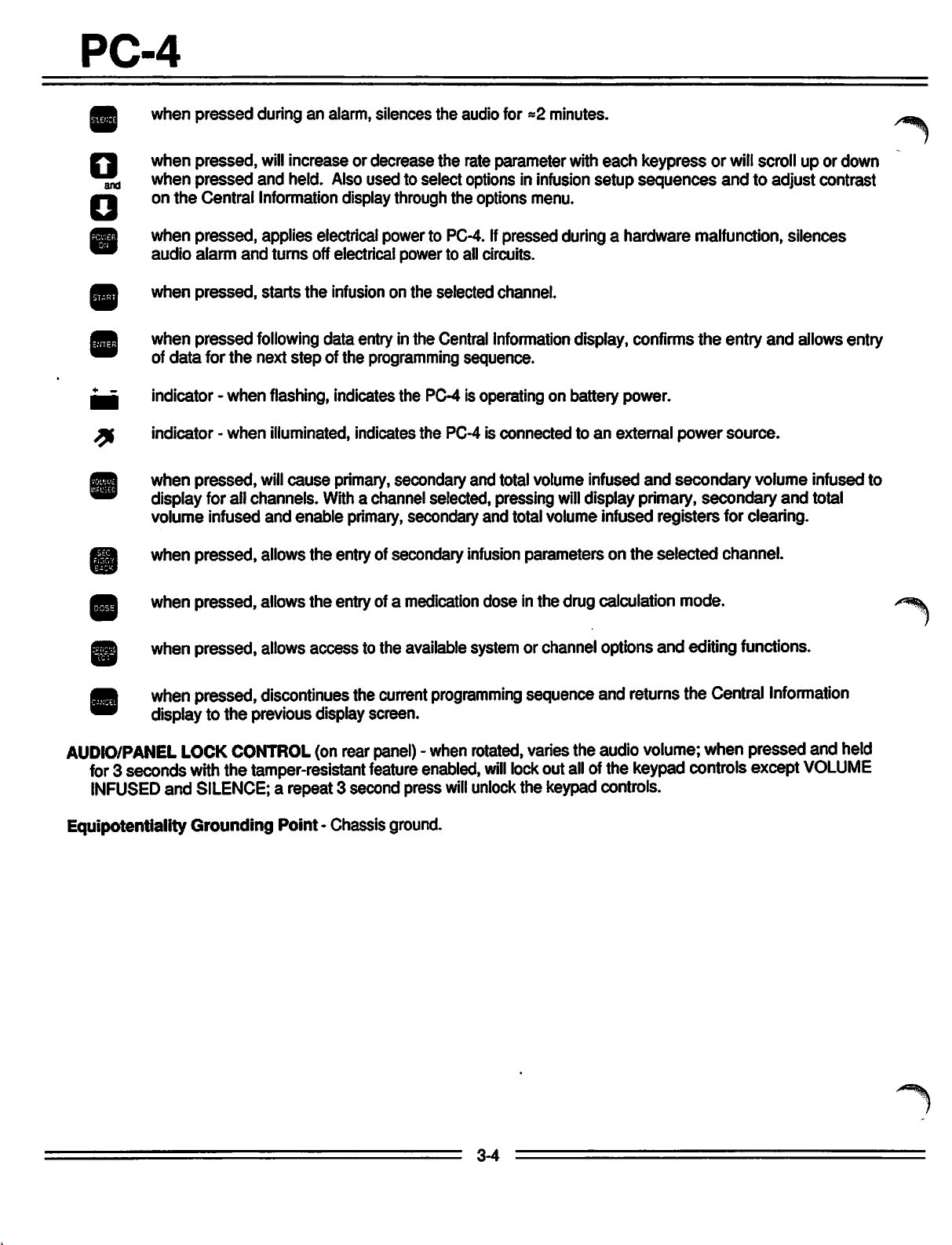
when
pressed
during an alarm, silences
the
audio for *2 minutes.
^
•J,
"I
when
pressed,
when
pressed
onthe Central
when
pressed,
audio
alarm
when
pressed,
when
pressed
of
data
for
indicator - when flashing, indicates the PC-4 is operating on battery power.
indicator -
when
pressed,
display for ail channels.
volume infused
when pressed, allowsthe entryofsecondary
when pressed, allows the entry of a medicationdose in the drug calculation mode.
will
increaseordecrease
and
held.
Also
usedtoselect
Information
applies electrical power to PC-4.Ifpressed
and
turns
starts
following data entry in the Central Information display, confirms
the
next
step
when
illuminated, indicates
will
cause
and
display
off electrical power to all circuits.
the
infusion on
of the programming sequence.
primary, secondary
With
a channel selected, pressing
enable primary,secondary and total volume infused registers for clearing.
the
through
the
the
selected channel.
the
PC-4 is
rate
parameter
with
optionsininfusion
options
and
infusion
menu.
during a hardware malfunction, silences
connectedtoan
total volume infused
will
display primary, secondary
parameters on the selected channel.
each
setup
external
keypressorwill
sequences
the
power
and
secondary
scrollupor
andtoadjust
entry
and
allows entry
source.
volume infused to
and
down
contrast
total
//r^%
when pressed,
whenpressed, discontinues the
display to the previous display screen.
AUDIO/PANEL
for
3 seconds
INFUSED
Equipotentiality Grounding Point- Chassis ground.
LOCK
with
and SILENCE; a repeat 3 second press
allows
CONTROL
access tothe available systemor channel optionsand editingfunctions.
(onrear
the tamper-resistant
current
panel)
feature
-when
enabled,
programming
rotated,
will
lock
will
unlock
sequenceand returns the Central
Information
variesthe audio volume; when pressed and held
out
all
ofthe
keypad
the keypad controls.
controls except
VOLUME
3-4
 Loading...