

Imed Gemini PC-1 Service manual (2000)
irTiSftandflPTiSfr
ALAR1S
MEDICAL
SYSTEMS
imecl®
VOLUMETRIC
r
INFUSION
MAINTENANCE
PUMP/CONTROLLER
Gemini
pc-i
MANUAL

Cut
into
on
spine
binder
and
label
insert
holder
of
PC-1
#*N
PC-1
WARNINGS,
CAUTIONS
CAUTION: FEDERAL (USA) LAW
OR
ON
THE
USE
ONLY
PROPER
ACHIEVED
GRADE".
DANGER:
WARNING:
CAUTION:
ORDER
HOSPITAL
GROUNDING.
BY
EXPLOSION
FLAMMABLE
TO
FLO-STOP
TO
REMOVE
QUALIFIED
OFAPHYSICIAN.
GRADE
GROUNDING
CONNECTION
PREVENT
REDUCE
COVER
TOARECEPTACLE
HAZARD,
ANESTHETICS.
UNRESTRICTED
IS
OPEN.
RISK
SERVICE
AND
NOTICES
RESTRICTS
POWER
RELIABILITY
DO
OF
ELECTRICAL
OR
BACK.
PERSONNEL.
SUPPLY
NOT
REFER
THIS DEVICETO
CORD
USEINTHE
FLOW,
TO
CAN
ONLY
MARKED
CLOSE
SHOCK,
SERVICING
INSURE
"HOSPITAL
PRESENCE
CLAMP
DO
SALE
BE
NOT
TO
BY
OF
WHEN
#^
TO
MAXIMIZE
THAT
THIS
INSTRUMENT
TEMPERATURE
WARNING:
CAUTION:
THE
SERVICE
CONTROLLED
BE
REPLACE
BEFORE
LIFE
OF
STORED
BETWEEN
FUSE
CONNECTING
NOTE
THE
INSTALLED
AND
OPERATED
68°F
WARNING
AS
(20°C)
MARKED.
"REFER
BATTERY,
IN
AN
AND
77°F
TO
MANUAL"
IT IS
RECOMMENDED
ENVIRONMENT
(25°C).
THAT
IS
IN
THE
EVENT
BIOMEDICAL
THE
INSTRUMENTISDROPPED
TECHNICIAN
PRIOR
TO
USE
FOR
AT
ANY
PATIENT
TIME, IT
CARE.
MUST
BE
CHECKED
BY
A
PC-1
WARNING
AND
CAUTION
NOTICES
WARNING: TO PREVENT UNRESTRICTED FLOW,CLOSE ROLLER CLAMP WHEN FLO-STOP1
MECHANISM
CLASS
1
r\j
IS
OPEN.
CAUTION:
TYPECF(Equipment
ALTERNATING
REPLACE
EQUIPOTENTIAL
REFER
CURRENT
FUSE
ONLY
GROUND
TO
MANUAL
useable
WITH
for
direct
SAME
POINT:IFTHE
cardiac
TYPE
EARTH CONNECTION OR HOSPITAL EARTH
THE
INSTRUMENT
USING
INTERNAL
BATTERY
applications)
AND
RATING
INTEGRITY
SYSTEM
POWER.
OF
THE
EQUIPOTENTIAL
IS IN QUESTION,
OPERATE
IPX1
DRIP
PROOF
If
the
PC-1
pump/controllerisdroppedatany
instrument
ONLY
checked
equipment
that
by
the
has
shouldbeconnectedtothe
Port and
personnel.
Only
the
systems
connection should ONLYbeperformedbyqualified
that
have
been
shouldbeconnectedtothe
connectorand
qualified
the
personnel.
connection should ONLYbeperformed
WARNING
Biomedical
CAUTION
been
qualifiedtoIEC 601-1
PC-1
CAUTION
Department
pump/controller's RS-232-C Data
qualifiedtoIEC 601-1
PC-1
pump/controller's
time,
have
the
priortofurther
standards
standards
Nurse
Call
by
IV

NOTICE
PC-1
f*
Product design and/or specifications are subject to
change
in
This
Systems,™
data
personnel
without notice.
this
manualiscurrent
publication
Inc.
provided solely for
in repairing
The
contains
("ALARIS
the
ALARIS
information contained
asofthe
ALARIS
Medical")
use
of technical
dateofissue.
Medical
proprietary
Medical infusion
pump/controllers.
Noneofthe
duplicated nor
other
than
ALARIS
component
the
information
information
mayitbe
for
the
Medical infusion pump/controllers and
parts thereof.
contained
usertosubstantial
repair
liability.=
contained
utilized in
and
maintenance
Any
unauthorized
herein
herein
any
may
may
manner
of
subject
use
the
be
the
of
This
manual
written
consentofALARIS
ALARIS
Medical
I022I Wateridge
(858)458-7000
San
Diego.CA92I2I
may
not,inwholeorin
Systems,
Circle
USA
Medical
Inc.
part,becopied,
Systems,
Inc.
cCopyright
PrintedinUSA
US.
4.954.046; 4.859,927;5,219,330;
601.664;607,112;622,088;604,477. CA 1.235,033; 1,258,212; 1.300,977; 1,280,647; 1,296,791;2,020,926;
1,238,832.AT0,225,158. BE0225,158. FR 0.225,158; 283,614; 315.312; 0,431,726; 0,238,277. GB 0.225,158;
283,614; 315.312; 0,431,726; 0,238,277.NL0,225.158; 283,614.IT0,225,158; 283,614. SE 0,225,158;
283,614. CH 0.225,158. DE P3686558.3; P3772,556.9;
jp«9*SM 7
4§S*«1 9 6 7
OtherUS
IMED®,
Systems™.
photocopied,
Patents4,617,014; 4,689.043; 4,690,673; 4.725,205; 4,728,265; 4,836,752; 4,909,710; 4,920,336;
reproduced,
2000
ALARIS
54470^,»»»1
16
and
Foreign
Gemini
PC-I®,
translated,orconvertedtoany
Medical
Systems,
Inc.
D305.I5I;
8^;«W«1
Patents
Issued
Flo-Stop®,
8
7 9 3
and
Pending.
VersaTaper®,
electronicormachine-readable
All
Rights
Reserved
D308.946; D3I2.879. AU 646,216; 580,184; 586,594; 590.179;
16
8 7
11
9#;«W«M
AutoTaper®,
387I72IT2;
2#;»!*SM
P6908208; P3774598.TWUM5272I.
90238
7 3 0 3 9
are
registered
trademarksofALARIS
5#.
7f;
form
without
Medical
prior
PC-1
This manual contains operation
instructions for the
IMED8
VolumetricInfusionPump/Controller (aPC-1").
The information provided herein is intended for
use bytechnical personnel responsible for
servicingthis product. The material is divided into
six sections
and
is presentedasfollows:Section
1 - Descriptive Information; Section 2 -
Preparationfor Use; Section 3 - Operating
Instructions; Section 4 - Functional Description
and
Schematic
Maintenance
Diagrams; Section 5 -
Instructions;
and Assembly Drawings; Section 7 - Calibration
and
Preventive
Maintenance.
and
GEMINI
Section
PC-1®
6 -
PREFACE
maintenance
Parts
Lists
This
manual
Manuals
1310-9261-00
Addendum
The
features
supersedes
1310-9251-00
and
PC-1
P/N1310-9028-00.
of
the
220V
PC-1 Maintenance
and
1310-9261-00
International
modelofthe
PC-1
and
pump/controllerhave been incorporated into this
manual. Text or graphics that
exclusivelyto the 220V model
a
CEEfr
symbol.
In addition,
model of
some
features
the
PC-1 pump/controller only
are
are
related
are
identifiedwith
for
the
110V
and
are
identified with a GEE) symbol.
Additionalcopies of this manual maybeobtained
bycontacting
ALARIS
Medical's Customer
Service Department.
/^sk
VI
PC-1
•f^
^
SECTION
1.1
1 -
DESCRIPTION
Introduction
TABLE
OF
CONTENTS
1.2 Operating Characteristics 1-1
1.3
1.4
Operating
User
Interface
Condition 1-2
1.5 Physical Description 1-4
1.6
1.7
1.8
SECTION
2.1
2.2
2.3
2.3.1
2.3.2
Product
Operating
Accessories
2 -
PREPARATION
Introduction
Pre-Operational
Operational
Pre-operational
Pre-operational
2.3.2.1 Electrical
2.3.2.2
2.3.3
2.3.3.1
2.3.3.2
Electrical
Abbreviated
Test
Test
History 1-4
Specifications
FOR
USE
Mechanical
Performance
Check
Electrical
Leakage
Ground
Operational
Test
Test
Inspection
Check
Battery
Charge
Inspection
Performance
Test
Requirements
Procedures
1-1
1-3
1-5
1-5
2-1
2-1
2-3
2-3
2-3
2-3
2-3
2-3
2-3
2-4
SECTION
3.1
3.2
3 -
OPERATION
Introduction
Controls
and
Indicators
3.3 Operating Conditions 3-9
3.3.1 Normal
3.3.1.1
Pump
and
and
Computer
Controller
Operation 3-9
Modes
3.3.1.2 VersaTaper®/AutoTaper® ModeOperation 3-17
3.3.1.3 Battery Powered Operation 3-23
3.3.2 Maintenance/Diagnostic Mode 3-24
3.4
3.5 Audio Alert
SECTION
4.1
Operator
4 -
PRINCIPLES
Introduction
Information Display
System
OF
OPERATION
and
Alarm
Response
Procedures
4.2 Mechanical Operation 4-1
4.2.1 Physical Description 4-1
4.2.1.1 Pumping Mechanism 4-1
4.2.1.2 Strain
Beam
(Pressure
Transducer)
4.2.2 Functional Operation 4-1
4.2.2.1 Pumping Mechanism 4-1
4.2.2.2 Strain
Beam
(Pressure
Transducer) 4-5
4.3 Electrical/Electronic Operation 4-5
4.3.1 Functional Description 4-5
4.3.2 Functional Operation 4-8
3-1
3-1
3-9
3-25
3-25
4-1
4-1
VII
PC-1
4.3.2.1
4.3.2.2
4.3.2.3
4.3.2.3a
4.3.2.4
4.3.2.4a
4.3.2.5
4.3.2.5a
4.3.2.5b
4.3.2.6
4.3.2.7
4.3.2.8
4.3.2.9
4.3.2.10
4.3.2.11
4.3.2.12
4.3.2.13
4.3.2.14
4.3.2.15
4.3.2.16
4.3.2.17
4.3.2.17a
SECTION
Power
Auto
5 Volt
5V
±12
±8
Battery
Dual
Dual
System
Battery
On/PowerOff Subsystem
PowerOnSubsystem
Protected
Power
Volt DC
Volt DC
Charger
State
State
Reset
Depleted
Subsystem
Supply (-7023 Power Supply Board)
Power
Power
Supply
Supply
Subsystem
Battery
Battery
Charger
Charger
Circuit
Circuit
Subsystem
Subsystem
(Charger Adapter CCA)
(-7023 Power Supply Board)
Pumping Mechanism
Strain
Air-ln-Line
Slide
Door
Audio
Display
Communications Interface
Maintenance
Beam
Detector
Clamp
Sensor
Subsystem
Detector
Subsystem
Mode
and
Empty Container Detector (ECD)
Empty Container Detector (Universal)
5 -
MAINTENANCE
Signal Definitions
All
except
V8.xx
All
except V8.xx
4-9
4-9
4-9
4-9
4-12
4-12
4-12
4-13
4-13
4-15
4-15
4-17
4-32
4-34
4-35
4-35
4-37
4-37
4-40
4-40
4-53
4-53
5.1
5.2
5.2.1
5.2.2
5.3
5.3.1 Maintenance/Diagnostics Mode Operation
5.3.1.1 Maintenance/Diagnostics Mode
5.3.2
5.4
5.5
5.5.1
5.5.2
Introduction
Preventive
Cleaning
Maintenance
Instructions 5-1
Mechanical Inspection
Maintenance/Diagnostics Mode
Maintenance
Troubleshooting
Mode
Test
Suite
Disassembly
Separating
Front
the
Case
(Figure 6-1)
Case
Disassembly (Figure 6-2b)
Test
Sequence
5-1
5-1
5-2
5-2
5-2
5-3
5-3
5-10
5-36
5-36
5-36
5.5.2.1 Circuit Card Removal and Disassembly (Figure 6-2b) 5-36
5.5.2.2 Pumping Mechanism Assembly Removal (Figure 6-2a) 5-37
5.5.2.3 Door
5.5.2.4
5.5.2.5
AIL/SCD
Transducer
Sensor
Assembly Removal (Figure 6-2a) 5-37
Assembly Removal and Disassembly (Figure 6-2a) 5-37
Assembly Removal (Figure 6-2a) 5-37
5.5.2.6 Anchor Bracket Assembly Removal (Figure 6-2b) 5-38
5.5.2.7 Door Assembly Removal and Disassembly (Figures 6-2c
5.5.2.8
5.5.2.9
Pump
Snap
Seal
Removal (Figure 6-2c)
Bracket Removal (Figure 6-2c) 5-38
and
6-3) 5-38
5-38
5.5.2.10 Keypad/ESD Shield Assembly Removal (Figure 6-2a) 5-38
5.5.3
5.5.3.1 Battery Removal (Figure 6-1a)
5.5.3.2 Battery Bracket Removal. (Figure 6-1a)
Rear
Case
Disassembly
5-38
5-39
5-39
5.5.3.3 Transformer Harness Assembly Removal (Figure 6-8) 5-39
5.5.3.4 AC Power Input ModuleAssembly Removal(Figure 6-8) 5-39
PC-1
5.5.3.4a ChargerAdapter CCA Removal (Instruments
Modification Kit installed) 5-39
5.5.3.5
5.5.3.6 Pole Clamp Assembly Removal
5.5.3.7 Removal of
5.5.3.8
5.6
SECTION
6.1
SECTION
7.1
7.2
7.3
7.3.1
7.3.1.1 Calibration
7.3.1.2
7.3.2
7.4
7.4.1 Electrical
7.4.1.1 Electrical
7.4.1.2
7.4.1.3
7.4.1.4
7.4.1.5 Battery
7.4.2
7.4.2.1
7.4.2.2
7.4.3
7.4.3.1
7.4.3.2 Initialization
7.4.3.3
Power
Supply
Grounding
Reassembly
6 -
ILLUSTRATED
Introduction
7 -
CALIBRATION
Introduction
Preventive
Calibration
Strain
Calibration
AIL
Beam
Detector
Comprehensive
Electrical
Dielectric
Battery
Voltage
Care
Qualitative
Operational
VTBI
Display
Quantitative
Equipment
Pump
Mode
Board Removal 5-39
and
Disassembly (Figure 6-1a) 5-40
the
Power Cord
Stud
Removal
PARTS
AND
Maintenance
Procedures
Calibration
Equipment
Procedures
Calibration
Operational
Strap
BREAKDOWN
PREVENTIVE
Requirements
Performance
(Figure 6-1c) 5-40
MAINTENANCE
Inspection
Leakage
Ground
Test
Test
Test
(Optional)
Check
and
Maintenance
Operational
Performance
Validity
Operational
Performance
Test
Check
Performance
Test
Test
Requirements
Setup
Tests
Test
with
DualState Charger
5-40
5-40
6-1
7-1
7-1
7-1
7-1
7-1
7-2
7-3
7-4
7-4
7-4
7-4
7-4
7-4
7-4
7-5
7-5
7-5
7-5
7-5
7-5
7-7
WARRANTY
NOTES
SALES
TECHNICAL
AND
SERVICE
SERVICE
OFFICES
MANUAL
SUPPLEMENTS
IX
PC-1
LIST
OF
FIGURES
Figure
1-1
1-2
2-1 PC-1 Front
2-2
2-3
2-4
3-1
3-1
a
3-2
4-1 PC-1
4-2
4-2a
4-3
4-4
4-4a
4-5
4-6
Title
IMED®
Audio
Gemini
Characteristics
and
PC-1®
Rear
Volumetric
Operating
Infusion
Features
Pump/Controller
Communications Emulator Plug 2-4
Air-ln-Line
PC-1
PC-1
PC-1
PC-1
Simulator
Test
Data
Front
Panel
Titration
Rear
Panel
Pumping
Sheet
Controls
Front
Panel
Controls
Mechanism
and
Controls
and
Indicators
Indicators
and
Indicators
Functional Block Diagram [v2.xx/5.xx/6.xx]
Functional Block Diagram [v7.xx]
Cross
Section of Strain
Beam
Assembly
PC-1 Interconnect Diagram
PC-1 (220V) Interconnect Diagram
MicroprocessorTiming Waveforms
Power
ON/OFF, Auto
PowerOnand
Sensor
Signal Functional
Schematic
[v2.xx/5.xx/6.xx]
4-7
4-8
4-8a
4-9
4-10
4-11 Relationship of
4-12
4-12a
4-12b
4-12b
4-12c Power Supply CCAwith Crowbar/Timer (PC-1CE V8.xx)
4-12c
4-13
4-14 Input Signal
4-15
4-16
4-17
4-18a
4-18b
4-18c
4-18d
4-19
4-20
4-20a
5 Volt
±12
Charger
System
Stator
Volt
Battery
Battery
Power
Power
Power
Protected
Power
Circuit Functional
Schematic
[v2.xx/5.xx/6.xx] 4-11
Supply Functional Schematic [v2.xx/5.xx/6.xx]
Adapter Board Schematic (with Mod Kitinstalled)
Reset
Functional Schematic [v2.xx/5.xx/6.xx]
Polarity
Charger
Charger
Supply CCA [v7.xx]
Supply CCA [v7.xx]
Changeasa Function of
Stator
and
Rotor Teeth with
Phase
theAPhase
Functional Schematic (without Dual
Functional Schematic Pwr
(Sheet
(Sheet
1)
2)
Sup
Excitation
State
Brd (Dual
Supply CCA with Crowbar/Timer (PC-1CE V8.xx)
Energized
Charger)
State
Charger)
(Sheet
(Sheet
1) 4-27
2) 4-29
Pumping Mechanism Functional Schematic [v2.xx/5.xx/6.xx] 4-31
Pulses
Strain
AIL
Slide
Beam
Detector
Clamp
Functional Schematic [v2.xx\5.xx\6.xx]
Cross
Detector
Hybrid AIL/SCD Board
AIL/SCD
AIL/SCD
AIL/SCD
PC-1 Audio
PCB
Schematic
PCB
Subsystem
and
Section
Cross
Schematic
Schematic
ChangeinPhase
Section
Schematic
[v2.xx/5.xx/6.xx]
Excitation of Unipolar Drive 4-32
Display CCA Schematic [v2.xx/v5.xx] 4-41
Display CCA Schematic [v6.xx] 4-43
4-20b Display CCA Schematic [v7.xx]
4-20c Display CCA Schematic [PC-1CE v8.xx] (Sheet 1) 4-47
4-20c Display CCA Schematic [PC-1CE
4-21
4-22
4-22a
Communicatons
ECD
Schematic
ECD (Universal)
Interface
Schematic
Functional
v8.xx]
(Sheet 2) 4-49
Schematic
Page
xiii
1-8
2-2
2-8
2-9
3-2
3-3
3-4
4-2
4-3
4-4
4-5
4-6
4-7
4-8
4-10
4-14
4-14
4-16
4-17
4-17
4-19
4-21
4-23
4-25
4-33
4-34
4-35
4-35
4-36
4-36
4-37
4-39
4-45
4-51
4-53
4-54
PC-1
4-23
4-23
4-23
4-24
4-24
4-24
4-24a
4-24a
4-24a
6-1
6-1
6-1
6-2a
6-2b
6-2c
6-3
6-4
6-5
6-6
6-7
6-8
6-9
6-10
7-1
7-2
7-3
Microprocessor Interface Schematic [v2.xx/5.xx/6.xx] (Sheet 1) 4-55
Microprocessor Interface Schematic [v2.xx/5.xx/6.xx] (Sheet 2) 4-57
Microprocessor Interface Schematic [v2.xx/5.xx/6.xx] (Sheet 3) 4-59
Logic CCA Schematic
Logic CCA Schematic [v7.xx](Sheet 2) 4-63
Logic CCA Schematic [v7.xx] (Sheet 3) 4-65
Logic/AnalogCCA Schematic
Logic/Analog CCA Schematic
Logic/Analog CCA Schematic
a
b
c
Parts
Parts
Parts
Parts
Parts
Parts
Parts
Parts
Parts
Parts
Parts
Parts
Parts
Parts
Universal
Air-ln-Line
PC-1
Ident
Identi
Identi
Identi
Identi
Ident
Ident
Identifi
Identifi
Ident
Ident
Ident
Ident
Ident
Test
fi
cation PC-1 Final
cation PC-1 Final
cation PC-1 Final
cation Front
cation Front
cation Front
cation Door
cation Logic
cation Logic
cation Display Circuit Card
cation Display Circuit
cation
cation
cation Power
Test
Station
Simulator
Data
Sheet
[v7.xx]
Rear
Power
Setup
(Sheet 1) 4-61
[PC-1CE
[PC-1CE
[PC-1CE
v8.xx] (Sheet 1) 4-67
v8.xx]
v8.xx]
(Sheet
(Sheet
2) 4-69
3) 4-71
Assembly
Assembly
Assembly
Case
Assembly
Case
Assembly
Case
Assembly
Assembly
CCA
[v7.xx]
CCA
[v8.13]
Case
Supply
Supply
Assembly
Assembly
CCA
CCA
Assembly
[v7.xx]
[v8.13]
[v7.xx]
[v8.13]
6-5
6-6
6-7
6-10
6-11
6-12
6-14
6-19
6-20
6-23
6-24
6-26
6-32
6-33
7-10
7-11
7-12
»
PC-1
LIST
OF
TABLES
Table
Title
Page
1-1 Product History 1-5
1-2 Operating Requirements 1-6
1-3 Performance Specifications 1-6
1-4
3-1
Accessories
PC-1
Controls
and
Indicators
1-9
3-5
3-2 PC-1 Status/Alarm Displays 3-26
4-1 RS-232-C
5-1 Troubleshooting/Fault Isolation Guide
5-2 PC-1 Error Log
5-2a
PC-1 Error Log
5-2b PC-1 Error Log
5-2z
5-3
6-1
6-1a
6-2
6-3
6-4
6-5
6-6
6-7
PC-1
TableofTorque
Parts
Parts
Parts
Parts
Parts
Parts
Parts
Parts
Communications
Codes
Codes
Codes
Maintenance
(V2.xx, V5.xx, V6.xx,
(V7.xx) 5-21
(V8.xx) 5-29
Mode
Values
List - PC-1 Final
List - PC-1 Final
List - Front
List - Door
Assembly
Assembly
Case
Assembly
Assembly
List - Logic Circuit
List - Display Circuit
List -
Rear
Case
Assembly
List -
Power
Supply
Error
Card
Card
Circuit
Data
Port Signal Definitions 4-32
and
V6.3x/4x) 5-14
Codes
Assembly
Assembly [v7.xx &
(v5.xx/v6.xx/v7.xx/v8.xx) 5-35
[v7.xx &
subsequent]
subsequent]
Card
Assembly
for [v7.xx &
subsequent]
5-10
5-41
6-2
6-3
6-8
6-13
6-15
6-21
6-25
6-27
/•*il|v
XII
PC-1
irned
COHTV3LLK
D
S o
Gemini
»uu»
Sl»«ai
000
S C
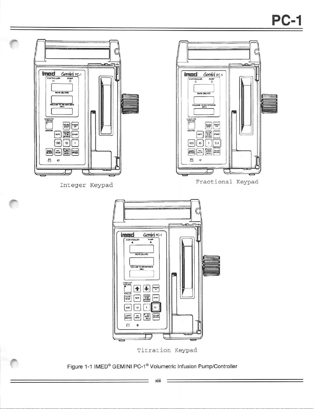
Integer
pc-
i
t
Keypad
I
imscl
«5UH
co"
0 c
YOV.UUI
•ATI
GernW
(ML/HR)
TO BE
Pit)
HJU»
«iFUtU
pc-i
I
•
BHnEI
a cr
C
s c
Fractional
Keypad
Figure 1-1
IMED®
imtad
COHTROU1K
Case
0000
a »
GEMINI
Gemini
• •
FIATU(L«_><R)
V<XtUC
TOBCHFUSEO
ET^
Titration
PC-1®
pc-i
«»»
Keypad
Volumetric Infusion Pump/Controller
XIII
PC-1
SECTION
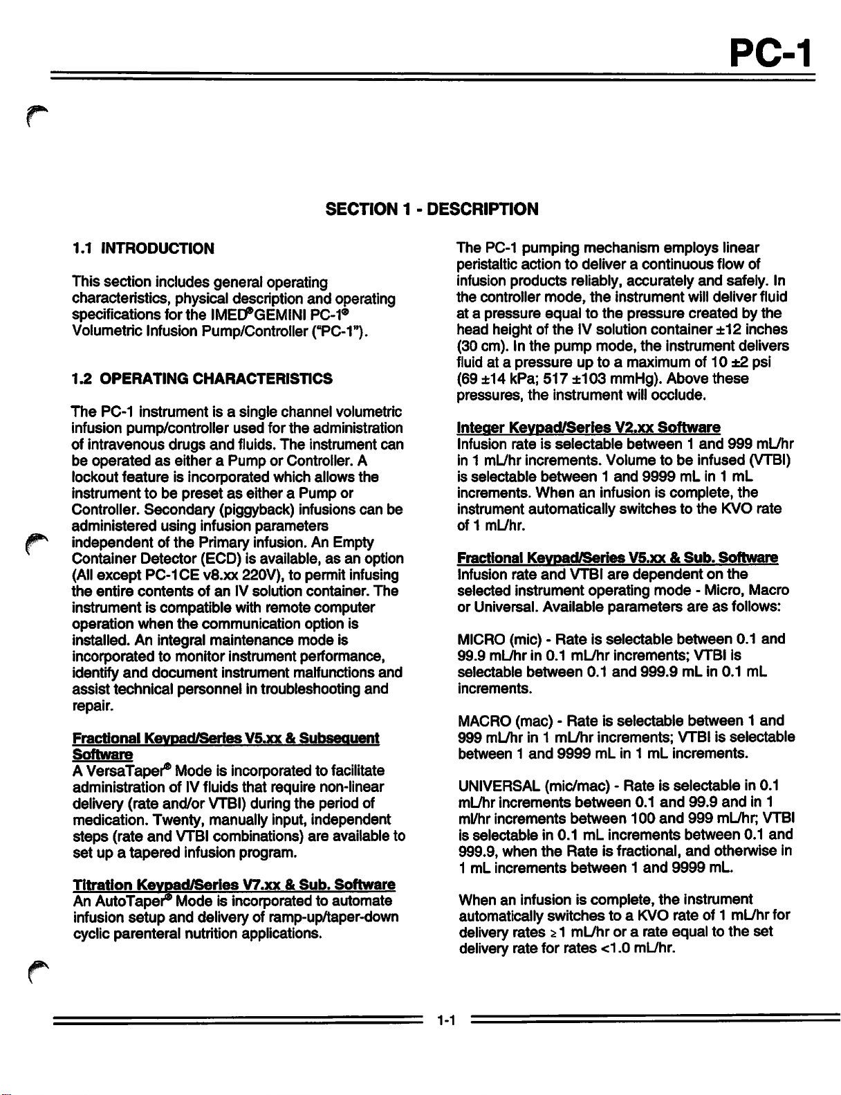
1.1
INTRODUCTION
This section includes general operating
characteristics, physical description
specifications for the
IMED®GEMINI
and
PC-1®
operating
Volumetric Infusion Pump/Controller ("PC-1").
1.2
OPERATING
The
PC-1
instrument
infusion pump/controller
intravenous
of
be
operated
lockout
featureisincorporated
instrumenttobe
Controller.
Secondary
administered
independentofthe
Container
(All
except
the
entire
Detector
PC-1CE
contents
instrumentiscompatible
operation
when
installed. An integral
CHARACTERISTICS
is a single
used
drugs
and
fluids.
as
eitheraPumporController. A
channel
for
the
The
administration
instrument
which allows
presetaseitheraPump
(piggyback) infusions
using infusion
parameters
Primary infusion. An Empty
(ECD) is available,asan
v8.xx
220V), to permit infusing
ofanIV
the
communication
maintenance
with
solution
remote
container.
computer
option is
mode
volumetric
the
or
can
option
is
incorporated to monitor instrument performance,
identify
assist
document
technical
personnel
instrument malfunctions
in troubleshooting
and
and
repair.
Fractional
Software
Keypad/Series
V5.xx&Subsequent
AVersaTaper® Mode is incorporatedto facilitate
administration of IVfluids
delivery (rate
and/or
medication. Twenty, manually input,
steps
(rate
and
VTBI combinations)
set
up a
Titration
An
AutoTaper®
infusion
cyclic
tapered
Keypad/Series
setup
parenteral
infusion program.
Mode is incorporatedto automate
and
delivery of ramp-up/taper-down
nutrition applications.
VTBI)
that
require non-linear
during
the
independent
are
V7.xx&Sub.
period of
available to
Software
can
The
and
1 -
be
DESCRIPTION
The
PC-1
pumping
peristaltic action to deliver a
infusion
the
atapressure
head
(30 cm). In
fluid at a
(69 ±14 kPa;
pressures,
Integer
Infusion
in 1 mL/hr
is
increments.
products
controller
height of
Keypad/Series
selectable
mode,
equaltothe
the
the
pump
pressure
517
the
instrument
rateisselectable
increments.
between
When
instrument automatically
of1mL/hr.
Fractional
Infusion
selected
Keypad/Series
rate
and
instrument
or Universal. Available
MICRO(mic) -
99.9
mL/hrin0.1
selectable
increments.
Rateisselectable
between
MACRO(mac) -
999
mL/hr in 1
between1and
mL/hr
9999
UNIVERSAL(mic/mac) -
mL/hr
increments
ml/hr
increments
is
selectable
999.9,
1
mL
increments
when
in
the
0.1
Whenaninfusion is
automatically switches to a
delivery
delivery rate for
rates;>1 mL/hr or a rate
rates
mechanism
reliably,
the
instrument
IVsolution
mode,
employs
continuous
accurately
pressure
container
the
instrument
linear
flow of
and
safely. In
will
deliver
createdbythe
±12
delivers
up to a maximum of10±2 psi
±103
mmHg). Above
will
occlude.
V2.xx
Software
between
Volumetobe
1
and
9999
an
infusion is
complete,
switchestothe
V5.xx&Sub.
VTBI
are
dependentonthe
operating
mode
parameters
mL/hr
increments;
0.1
and
999.9
Rateisselectable
increments;
mL
in 1
mL
these
1
and
999
infused
mL
in 1
mL
the
KVO
Software
- Micro, Macro
areasfollows:
between
VTBI is
mLin0.1
0.1
between1and
VTBI is
increments.
selectable
Rateisselectable
between
between
mL
Rate
between1and
complete,
0.1
and
100
and
increments
is fractional,
the
KVO
99.9
and
999
mL/hr; VTBI
between
and
otherwise
9999
mL.
instrument
rate of 1 mL/hrfor
equaltothe
<1.0
ml_/hr.
fluid
inches
mL/hr
(VTBI)
rate
and
mL
in 0.1
in 1
0.1
and
set
in
1-1
PC-1
This version of
incorporates a
be
preset
Universal (mic/mac)
Rate
Titration
The
Rate
increased or
0.01 mL/hr (MICRO mode) with
O orO
new
control,
rate.
pressing
until
the
desired
to
accept
The
PC-1 pump/controller
operational warm up. An internally
provides normal
enable
external
use
in either
Titration
decreased
Greater
and
holding
the
new
when
power
the
PC-1 pump/controller
feature
Keypad/Series
that
allows
the
Micro (mic), Macro (mac) or
mode.
feature
allows
1 mL/hr (MACRO
then
press
START
rate
changes
the
appropriate
rateisobtained,
rate.
does
operation
AC
source
for a limited
powerisnot
is interrupted.
v7.xx
each
canbeachieved
not require
the
instrument to
the
ratetobe
mode)
pressofthe
toaccept the
© ©
controls
then
press
START
any
mounted
availableorthe
battery
period
to
or
by
pre
1.3
OPERATING
The
PC-1 pump/controller
independently (Normal Operation) or,
configured with a
computer
Normal
modes
controlled
operation
plus
operation includes
Control
NORMAL
SETUP
The
modes.
OPERATION
MODE
Titration
Mode (refer to Section 2.3.3.2) to configure
CONDITION
communication
includes
the
Maintenance
the
V7.xx
keypad
canbeoperated
data
device
(Computer Operation).
the
Controller
mode.
Monitor
and
and
Computer
subsequent
instruments utilize
when
port,asa
and
Computer
software
the
Setup
the
Pump
instrument for specific infusion regimes, language
selection
parameters.
and
communication
(serial port)
The
PC-1 pump/controller's
of a front
panel
tactile keypad
Audio Control potentiometer.
operation is provided through
utilize a
change
instructions
instrument
prescribed
infusion
are
printed on
case.
key
parameters.
Functional control is provided by a
16 bit microprocessor using a
includes a diagnostic routine
performance, provides audio
ensure
initiates
hardware
Sufficient
provide
proper
an
alarminthe
malfunction
disposable
the
user
sequencing
configurations
with a full
combinations (see Section 1.7). The
the
GEMINI
prevents free flow in
administration
the
user
interface
and
Tamper
the
press
sequencetoenter
Basic operating
the
right
stored
that
and
of normal
eventasoftware
is
detected.
rangeofset-up
set's
pumping
event
the
the
rear
resistant
requirement
sideofthe
program
monitors
visual
signals
operations
or
are
available
Flo-Stop®
segment
tubing
set
removed from the instrument following initial
installation.
operator
perform a gravity infusion in
instructions provided in
Free
action, is
flow,asa
possible
the
resultofdeliberate
when
using
the
accordance
set
package.
with
consists
panel
to
that
pump
to
and
on
is
set
to
the
or
to
CONTROLLER
In
the
CONTROLLER
pump/controller is
infusion of a
instrument
and
patient-side
specific
senses
gravity infusion.
measures
container
tubing in-line
exceeds
condition
delivery
container
and
pressure.
tolerance is
the
and
pump
exists
pressure
height;
decreasing
Controller
±12
hydrostatic
compares
pressure.
input
the
container height.
pressure
seconds
condition which
pressureisabove
transients
longer
required to
excess
alarm.
above
duration
above
than60seconds
compensate
of30minutes
MODE
mode,
programmed
volume
and
pressure
The
instrument's
the
of IVsolution.
responds
in a
manner
pressure
that
pressure
When
in-line
PC-1
to control
to container height
similarto a
pressure
from
against distal
pressure
pressure,anocclusion
and
an
alarmisinitiated.
is directly proportional to
increasing
height
mode
inches
Transient
the
occlusion
will
produce
stops
the
the
occlusion threshold for periods
container
reduces
occlusion
height
occlusion
pressure
(30.54 cm) from
surges
in patient-side
thresholdof<60
a LOW FLOW
the
infusion while
occlusion
durationorcumulative
threshold.
the
for volumetric deficiency in
will
initiate
an
occlusion
the
The
sensor
the
Actual
the
Pressure
^ik
fluid
raises
fluid
time
1-2
PC-1
f
PUMP
Inthe PUMP mode of operation,
employs a
psi (69 ±14 kPa;
nominal container height of24inches
a delivery rate >30 mL/hr.
mL/hr,
ensure
transient
generate
Software
These
independent
mode
occlusion
Software
These
independent
mode. This
increased
MAINTENANCE/DIAGNOSTIC
Integer/Fractional
The
by biomedical
maintenance
when
patient.
biomedical
loop
pumping
by
conditions. Specific
the
configuring
and
detailed
MODE
the
instrument
preset
occlusion
517
±103 mmHg) predicated on a
pressure
limitof 10 ±2
(61 cm)
For
the
occlusion
delivery
pressureisrate-dependent
rates
timely detection of occlusion conditions. Any
distal in-line
a patient-side
Release
instruments
(10
will
result in significantly
for
rates
Release
instruments
(517 mmHg)
mode
time-to-occlusion
Maintenance
pressure
occlusion
V6.xx
can
psi)
and
be
locked
occlusion
Subsequent
increased
<30
mL/hr.
v8.13
only
can
be
locked
occlusion
will
result in significantly
for
Keypad
Instruments
modeisintended
above
alarm.
intoarate-
pressure
intoarate-
pressure
rates
<30
MODE
solely
this
mode.
time-to-
mL/hr.
technicianstoperform servicing
the
PC-1 pump/controller is
The
service
diagnostic
mechanismtobe
stoppages
maintenance
the
computer
actions
maintenance
resulting from
operation
and
must
NEVER
be
connectedtoa
mode
provides
personnel
test
routines
sub-routines
test
sequencetopermit
accesstothe
and
allows
operated
alarm
and
are
the
unencumbered
malfunction
incorporated
instrument for non-English
(see
Section
5.3
for
operation).
and
<30
to
limit will
This
for
use
and
used
closed
language
in
COMPUTER
Fractional/Titration
Release
MONITOR
The
Monitor
monitor
performance.
V6.xx
MODE
mode
infusion
OPERATION
Keypads
and
Subsequent
allows a host
status
Monitor
and
instrument
modeisenabled
computerisconnectedtothe
through
and
COMPUTER
The
once
host
operationisselected
CONTROL/MONITOR
has
operation is confirmed by
indicator
steady
1.4
The
tactile
infusion. Delivery
Volumetobe
the
Communications
the
Monitor
CONTROL
Computer
set
computer
been
Control
up,tobe
installation.
established.
presentation
illumination.
USER
INTERFACE
front Control
keypad
for
Infused
indicatorisilluminated.
mode
controlled
Computer
by actuating
switch
Computer
the
changing from flashing to a
and
Display panel incorporates a
operator
mode
use
(ifnot locked),
are
each
infusions. A SEC/PIGGYBACK
permits
a
are
volume
control allows
resumedorstopped.
parameters
displayed
operator
independent
sequential
provided to
infused quantities.
for
digitally in
information display
selection of Rate
secondary
accumulate
infusion.
Total
The
an
infusion to be "paused"
Rate
and
the
Primary or
the
respective displays.
presents
with
Software
ONLY
computer
to
when
a host
PC-1 pump/controller
Data Port (RS-232-C)
allowsaninfusion,
and
monitored by a
controlled
the
COMPUTER
after
Monitor
mode
controlled
computercontrol
in programming
Rate
selected
for Primary
(Secondary)
and
Separate
and
Secondary
an
and
key
VTBI
registers
PAUSE/STOP
and
then
VTBI
infusion
Secondary
are
The
visual
for
prompts, advisories, alarms and/or malfunctions
Titration
The
personnel
Keypad
Diagnostic
accesstothe
routines, allows
operated
uninterrupted by
alarm conditions
recent
error
codes
operation).
Instruments
mode
provides biomedical
closed
the
pumping
stoppages
and
maintains
(see
Section
service
loop
diagnostic
mechanismtobe
resulting from
a log of
5.3
the24most
for
detailed
messagesasappropriate to
programming
Fractional
The
0.1,10,100,
and
operating
Keypad/Series
VTBI, VI,PCand
CLEAR/SILENCE keys have a secondaryfunction
during instrument
power
assist
the
instrument.
V5.xx&Sub.
up to
enableorclear
the operation in
Software
1-3
PC-1
discrete
these
Titration
The
(S)
decrease
feature
implemented using
Tamper
The
administration
door
flow," inhibits
prohibits
Open
pump
delivery
versionsofthe
Keypad/Series
keypad
which
enablethe user to
the
is
enabled
Resistance
requirement
will
close
mode
selections
PC-1 pump/controller.
addsthe rate
rate
parameter.Atamper
in
the
the
push
Control on
to properly install
set's
integral Flo-Stop
and
latch
premature
useofan
and
Air-in-Line
unauthorized
sensors
operationifeitherofthese
available on
V7.xx
SETUP
titration
quickly
&
Sub.
controls
increaseor
mode
actuation of
the
rear
the
before
prevents
inadvertent "free
operationofthe
set.
The
are
provided to
conditions
Software
tQj
and
resistance
and
the
Audio/
panel.
the
pump
Door
stop
occur
and
duringaninfusion. A strain relief fitting is provided
in
the
instrument's
kinking of
The
rear
panelofthe
the
configured with
ECD
connection
PC-1CEv8.xx 220V). A
connector
board
Software
the
PC-1 pump/controller for
operation.
IMED®
sets
is incorporated on
for
the
releases
GEMINI
are
required
Infusion Pump/Controllers. Sufficient
available to
and
configurations.
1.5
PHYSICAL
The
PC-1
characteristics:
Height:
Width:
Depth:
supportabroad
instrument
10.8
8.4
6.5
Weight: 11.1
The
PC-1 instrument
assemblies:
handle
supporttoprevent
proximal tubing.
PC-1 pump/controller is
an
audio
(ECD
Fractional
V6.xx
volume
connection
RS-232-C
Keypad
and
control
- All
data
the
power
instruments.
subsequent
computer
except
port
supply
controlled
Series disposable administration
for
use
with
the
GEMINI family of
set
DESCRIPTION
inches
inches
inches
pounds
the
front
range
has
the
(27.5 cm)
(21.3
cm)
(16.5
cm)
(5.1 kg)
consistsoftwo
and
rear
of infusion
following physical
w/pole
w/pole
clamp
clamp
major
case.
and
enable
types
an
are
types
FRONT
The
injection molded, plastic
an
houses
door,
transducer
detectors,
front
REAR
The
aluminum shell which
ally
(with sonalert), ECD
v8.xx 220V),
232-C connector)
exterior of
ECD
CASE
front
case
assembly
Electro-Static
and
supports
the
peristaltic pumping
(strain
the
multi-card
case
ESD
components.
CASE
rear
case
assembly
the
battery, transformer,
audio
and
the
rear
storage
fitting, power
consists
of a high-impact,
case/insert
Discharge
the
(ESD)
pumping
mechanism,
beam),
Air-in-line
assembly,
consists
mounts
of a
and
power
connector
control potentiometer
power
case
supports
entry
cord
(except
module.
the
retention
coating,
chamber
supports
supply
power cord retainer.
only.
The
exterior of
the
220V
AC
power
entry
equipotentiality grounding point.
module includes
fuses
220V AC power interrupt switch
1.6
PRODUCT
The
initial
Pump/Controller
time a
release
Controller,itdelivers
increments
delivered
numberofchanges
PC-1 isan"Integer" Infusion
fluidinwhole
and incorporated
feeding
interface with
change
allows
algorithm.
incorporated "Rate Titration"
the
HISTORY
releaseofthe
wasinOctober
only.
The
"VersaTaper®"
Then
the
RS-232 bus.
usertoincrease/decrease
small increments with a minimum
the
rear
module
for both input
Gemini
have
fluids in
next
iteration of
and
fractional
the
PC-1
whole
The
case
plus
The
(where
PC-1®
1988.
occurred.
an intravenous
was
number
presses. This modelalso incorporated
which is a predefined intravenous
algorithm.
their keypads,
is
the
key
keysisthe
Table
These
The
"Integer" model.
isthe
"Fractional"
"Titration/Fractional"
1-1 for
product
instruments
Keypad without a fractional key
The
Keypad
model.
history.
feeding
canbeidentified by
with a fractional
The
Keypad
model.
assembly
pressure
and
slide
keypad
die-cast
board
PC-1CE
and
The
pole
clamp,
strap
supports
the
power
leads
applicable).
Infusion
Since
The
Pump/
number
PC-1
increments
updated
last
major
keys
which
the
rate
of key
AutoTaper®
with
Refer
with
which
access
clamp
and
intern
RS-
entry
and
that
by
to
/^Ik
and
a
initial
to
t4
1-4
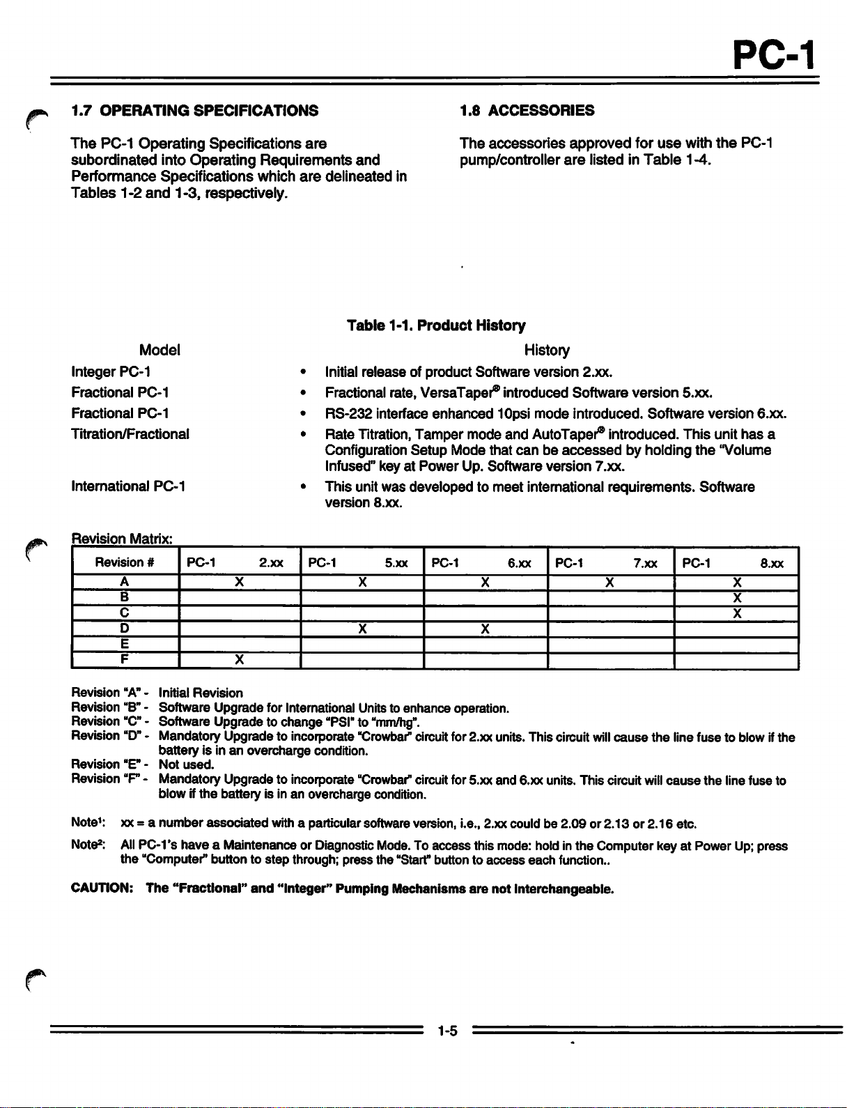
1.7
OPERATING
The
PC-1
Operating
subordinated
Performance
Tables
1-2
SPECIFICATIONS
Specifications
into
Operating
Specifications
and
1-3, respectively.
are
Requirements
which
are
delineated
and
PC-1
1.8
ACCESSORIES
The
accessories
pump/controller
in
approved
are
listed in
for
Table
use
with
1-4.
the
PC-1
Model
Integer
Fractional
Fractional
Titration/Fractional
PC-1
PC-1
PC-1
Initial
Fractional
RS-232
Rate
Configuration
Infused" key at
International
Revision
Revision
Revision
Revision
Revision
Revision
Revision
PC-1
Matrix:
#
PC-1
A
B
C
D
E
F
"A" -
Initial
Revision
"B"
- Software Upgrade for InternationalUnitsto enhance operation.
"C"
- Software Upgrade to change "PSI"to
UD"
- Mandatory Upgrade to incorporate "Crowbar" circuitfor 2.xx units. This circuit
battery is inanovercharge condition.
"E"-Not
used.
2.xx
X
X
This unit
version
PC-1
Revision"F- Mandatory Upgrade to incorporate
blow ifthe battery is in an overcharge condition.
Table
1-1.
Product
History
History
releaseofproduct
rate,
VersaTaper®
interface
Titration,
enhanced
Tampermodeand
Setup
Power
was
developedtomeet
8.xx.
5.xx
X X X X
X
PC-1
"mm/hg".
"Crowbar"
circuitfor 5.xx and 6.xx units. This circuit
Software
version
2.xx.
introduced Softwareversion 5.xx.
10psi
mode
introduced.
AutoTaper®
Mode
that
canbeaccessed
Up. Software version 7.xx.
international
6.xx
X
PC-1
Software
introduced.This unithas a
by holding
requirements.
7.xx
will
cause
will
the
the
Software
PC-1
line fuse to blow ifthe
cause
the line fuse to
version
"Volume
X
X
6.xx.
8.xx
j^
Note1: xx = a
Note2:
All
PC-1's have a Maintenance or Diagnostic
the
CAUTION:
number
associated
"Computer" button to
The
"Fractional"
with a particular software version, i.e., 2.xx could be
Mode.
To access this mode: holdinthe Computer key at Power
step
through; press the "Start" button to
and
"Integer" Pumping Mechanisms are not interchangeable.
1-5
access
each
2.09or2.13or2.16
function..
etc.
Up;
press
PC-1
Parameter
Power
Required:
Battery:
Operating
Operating Humidity
Storage/Transport
Temperature
Range:
Temperature:
Range:
Storage/Transport Humidity:
Parameter
Table
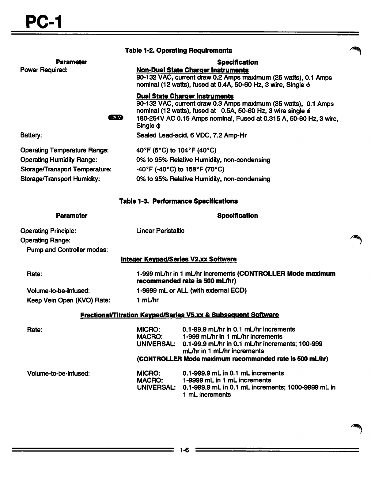
1-2.
Operating
Requirements
Specification
Non-Dual
90-132 VAC, current draw
State
Charger
Instruments
0.2
Amps maximum (25 watts), 0.1 Amps
nominal (12 watts), fusedat0.4A, 50-60 Hz, 3 wire, Single 6
Dual
State
Charger
Instruments
90-132 VAC, current draw 0.3 Amps maximum (35 watts), 0.1 Amps
nominal (12 watts), fused
180-264V
Single
Sealed
AC
0.15
Amps
(J)
Lead-acid, 6 VDC,
at
0.5A,
nominal,
7.2
Amp-Hr
50-60
Hz, 3 wire single 6
Fusedat0.315A,50-60
40°F(5°C)to104oF(40oC)
Table
0%to95%
-40°F
0%to95%
1-3.
Relative Humidity,
(-40°C) to
Relative Humidity,
Performance
158°F
(70°C)
Specifications
non-condensing
non-condensing
Specification
/«*§i||k
Hz, 3 wire,
Operating Principle:
Operating
Pump
Rate:
Volume-to-be-lnfused:
Range:
and
Controller
modes:
Keep Vein Open (KVO) Rate:
Fractional/Titration
Rate:
Volume-to-be-infused:
Linear
Integer
1-999
recommended
Peristaltic
Keypad/Series
mL/hr in 1 mL/hr
V2.xx
increments
rateis500
Software
1-9999 mL or ALL (with external ECD)
1
mL/hr
Keypad/Series
MICRO:
MACRO:
UNIVERSAL:
(CONTROLLER
MICRO:
MACRO:
UNIVERSAL:
V5.xx
0.1-99.9
1-999
mL/hr
0.1-99.9
mL/hr
in 1
Mode
0.1-999.9
1-9999
0.1-999.9
1
mL
increments
&
ml_/hrin0.1
mL/hrin0.1
maximum
mL
mL/hr)
Subsequent
in 1
mL/hr
mL/hr
increments
recommended
mLin0.1
in 1
mL
mL in
0.1
(CONTROLLER
Software
mL/hr
mL/hr
increments
increments
increments;
rateis500
mL
increments
increments
mL
increments;
Mode
maximum
100-999
mL/hr)
1000-9999
mL in
1-6
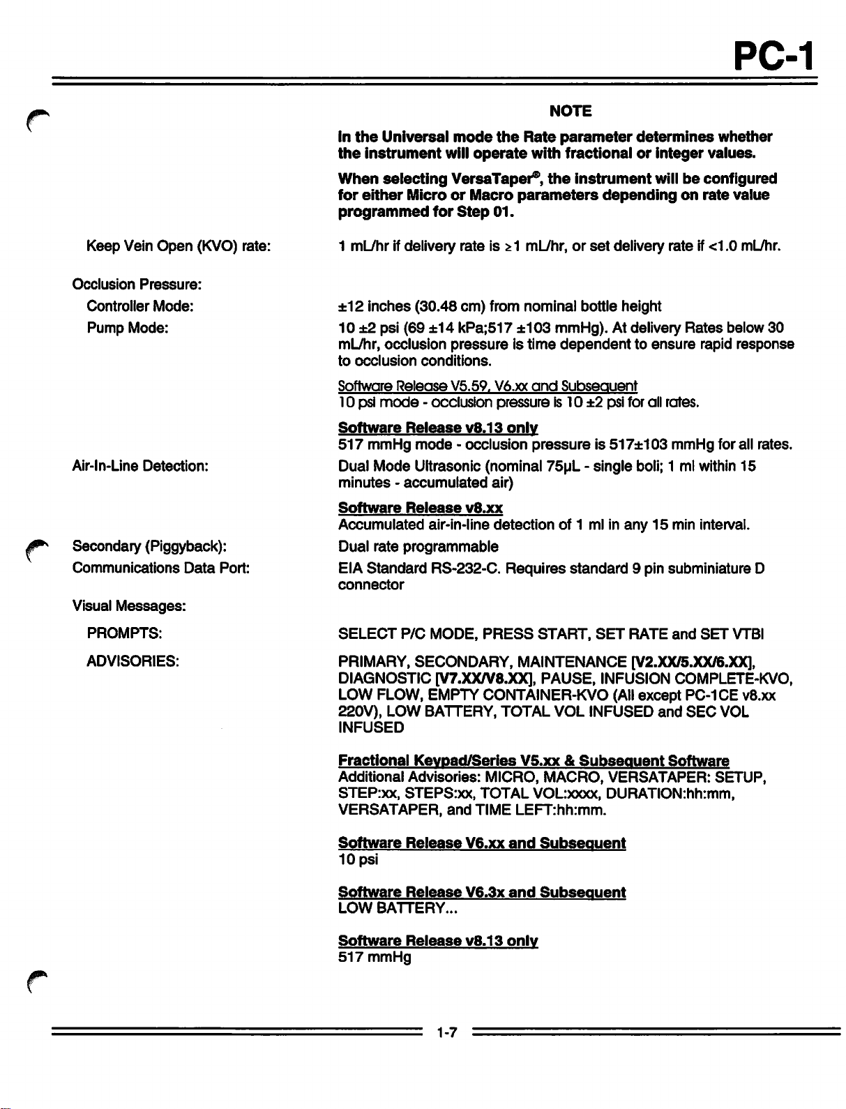
In
the
the
instrument
Universal
mode
will
the
operate
NOTE
Rate
parameter
with
fractionalorinteger
determines
PC-1
whether
values.
Keep Vein
Occlusion
Controller
Pump
Air-ln-Line
Pressure:
Mode:
Mode:
Detection:
Open
(KVO) rate:
#** Secondary (Piggyback):
Communications
Visual
Messages:
Data
Port:
When
for
programmed
selecting VersaTaper®,
either
MicroorMacro
for
Step
parameters
01.
the
instrumentwill be configured
1 mL/hr ifdelivery rate is ^1 mL/hr,orset
±12
inches
10
±2 psi (69
mL/hr, occlusion
to
occlusion
Software
10
psi
Software
517
mmHg
Dual
minutes-accumulated
Software
Accumulated air-in-line
Dual
EIA
Standard
connector
(30.48
±14
cm)
kPa;517
pressureistime
conditions.
Release
mode-occlusion
Release
Mode
Release
rate
programmable
V5.59,
v8.13
mode
- occlusion
Ultrasonic (nominal
v8.xx
RS-232-C.
from
nominal
±103
bottle
mmHg). At delivery
dependenttoensure
V6.xx
and
Subsequent
pressureis10±2psi for all
only
pressureis517±103
75uL-single
air)
detection
Requires
of 1 ml in
standard
depending
on
rate
value
delivery rate if <1.0 mL/hr.
height
Rates
below 30
rapid
response
rates.
mmHg for all rates.
boli; 1 ml within
any
15 min interval.
15
9 pin subminiature D
f*
PROMPTS:
ADVISORIES:
SELECT
P/C
MODE,
PRESS
START,
SET
RATE
and
SET
VTBI
PRIMARY, SECONDARY, MAINTENANCE [V2.XX/5.XX/6.XX],
DIAGNOSTIC [V7.XX/V8.XX], PAUSE, INFUSION COMPLETE-KVO,
(All
LOW FLOW, EMPTY CONTAINER-KVO
except
220V), LOW BATTERY, TOTAL VOL INFUSED
INFUSED
Fractional
Additional
STEP:xx,
VERSATAPER,
Software
10
psi
Software
LOW
Software
517
mmHg
Keypad/Series
Advisories:
STEPS:xx,
Release
Release
BATTERY...
Release
1-7
and
MICRO,
TOTAL
TIME
V6.xx
V6.3x
v8.13
V5.xx
&
MACRO,
VOLxxxx,
LEFT:hh:mm.
and
Subsequent
and
Subsequent
only
Subsequent
VERSATAPER:
DURATION:hh:mm,
PC-1CE v8.xx
and
SEC
Software
VOL
SETUP,
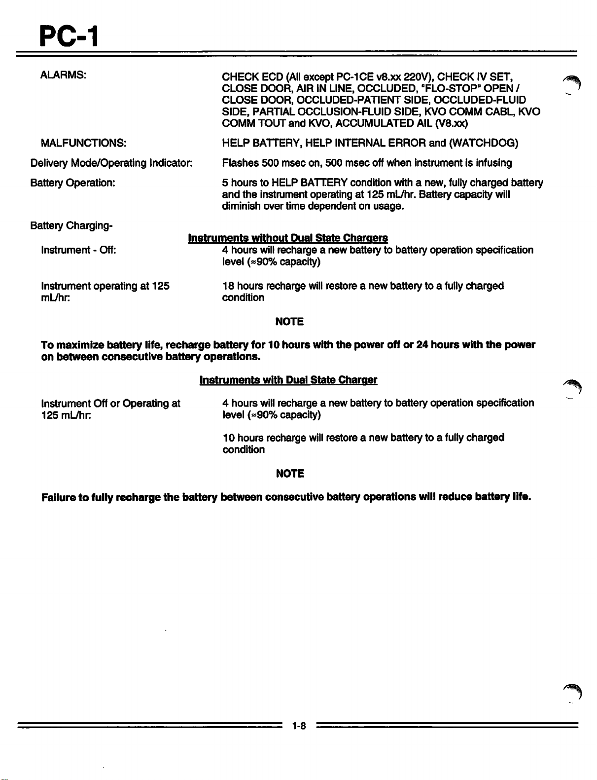
PC-1
ALARMS:
MALFUNCTIONS: HELP BATTERY, HELP INTERNAL
Delivery Mode/Operating Indicator:
Battery Operation: 5
CHECK
CLOSE
CLOSE
SIDE,
ECD
DOOR,
DOOR,
PARTIAL
COMM TOUT
Flashes
hours
and
diminish
500 msec on, 500 msec off when instrument is infusing
to HELP BATTERYcondition with a new, fully
the
instrument operating at
over
(All
except
AIR IN LINE,
OCCLUDED-PATIENT
OCCLUSION-FLUID
and
time
PC-1CEv8.xx
KVO,ACCUMULATED AIL(V8.xx)
dependent
Battery Charging-
Instruments
Instrument - Off: 4
hours
without
will
Dual
State
Chargers
recharge a new battery to battery operation specification
level (=90% capacity)
Instrument
mL/hr:
To
maximize
on
between
operatingat125
battery
life,
consecutive
recharge
battery
18
hours
condition
battery
operations.
recharge
for 10
NOTE
hours
will
with
restore a
the
power
220V),
OCCLUDED,
ERROR
125
mL/hr. Battery capacity
on
usage.
new
battery to a fully
offor24
SIDE,
SIDE,
"FLO-STOP"
KVO
CHECKIVSET,
OPEN
OCCLUDED-FLUID
COMM
and
(WATCHDOG)
hours
CABL, KVO
charged
charged
with
the
will
power
/%sf$k
/
battery
Instruments
Instrument Offor Operating at 4 hours
125
mL/hr: level
Failuretofully recharge
the
battery
(*90%
10
hours
condition
between
with
Dual
State
Charger
will
recharge a new battery to battery operation specification
capacity)
recharge
NOTE
consecutive
will
restore a
new
battery to a fully
charged
battery operations will reduce battery life.
1-8

PC-1
J^S
Audio
Characteristics:
AUDIO
(1) MALFUNCTION
(2)
KEY
CUCK
(3) ALARM
(4)
PROMPT
(5)
ADVISORY
(6)
CHANGEOVER
TYPE
v2jo(&xx/6.xx
v7joc
v2jo/5jocff>jcx
v7ja
CONSTANT
nn
600
msec
600
msec
30
msec
n_n
600
msec
AUDIO
TONE
nn
ON.
ON,3sec
ON (Once)
ON, 3
PERIOD
nn
0.5
sec
OFF
OFF
n n n
sec
OFF
an
ri_ji_jLJT_JiJi_n_Ji_JLJ^
600
msec
ON, 1.5
sec
OFF
100
msec
ON, 2
sec
OFF
100
msec
ON,15sec
lUULUUL
100
msec
ON, 400
OFF
msec
OFF(6 beeps)
rui_
n—r^
VAR/FIXED
ON
OFF
ON
OFF
ON
OFF
ON
ON
OFF
ON
OFF
ON
OFF
VOLUME
MAXIMUM
75db
FIXED
VARIABLE
VARIABLE
VARIABLE
VARIABLE
VARIABLE
SILENCE
YES/NO
NO
(v2.xx)
YES
(v3joc)
NO
YES
YES
YES
YES
J?N
Part
No.
1303
Description
Communications
Test
Plug (optional)
1308 EmptyContainer Detector
v8.xx)
20-2370-7
3299-100
Syringe
Calibrated
Holder
Tubing
(optional)
Figure 1-2.
Table
(for
use
with
Audio
Characteristics
1-4.
Accessories
Non-Universal
spike sets)
(dSD
and
prior to software
1-9
PC-1
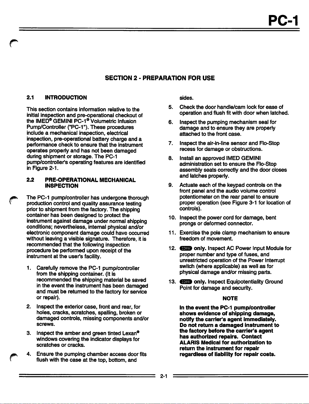
2.1
This
initial inspection
the
Pump/Controller
include a
INTRODUCTION
section
IMED®
GEMINI PC-1® Volumetric Infusion
mechanical
contains
and
(MPC-1").
information
pre-operational
These
inspection, electrical
inspection, pre-operational battery
performance
operates
during
pump/controller's
checktoensure
properly
and
has
shipmentorstorage.
operating
that
not
been
The
features
SECTION
relativetothe
checkout
procedures
charge
the
instrument
damaged
PC-1
are
2 -
of
and
a
identified
in Figure 2-1.
2.2
The PC-1 pump/controller
production control
priorto shipment from
container
instrument
PRE-OPERATIONAL
INSPECTION
and
quality
the
has
been
designed
against
damage
MECHANICAL
has
undergone thorough
assurance
factory.
to protect
The
testing
shipping
the
under normal shipping
conditions; nevertheless, internal physical and/or
electronic
without leaving a visible
recommended
procedurebeperformed
instrument at
1. Carefully remove
2.
3. Inspect the amber and green tinted
4.
component
that
the
the
user's
from
the
shipping container. (It is
recommended
in
the
event
and
mustbereturned to
or
repair).
Inspect
holes,
the
cracks,
damaged
screws.
the
the
exterior
scratches,
controls, missing
windows covering
scratches
Ensure
flush with
or
the
the
cracks.
pumping
caseatthe
damage
signature.
could
have
Therefore, it is
following inspection
upon receipt of
the
facility.
the
PC-1 pump/controller
shipping materialbesaved
instrument
case,
has
been
the
factory for service
front
and
rear, for
damaged
spalling, broken or
components
Lexan®
the
indicator displays for
chamber
access
top, bottom,
door
and
occurred
and/or
PREPARATION
5.
6. Inspect
7.
10.
11.
12.
13.
fits
FOR
USE
sides.
Check
operation
damage
attached
Inspect
recess
Installanapproved
administration
assembly
and
Actuate
front
potentiometeronthe
proper
the
door
handle/cam
and
flush fit with
the
pumping
mechanism
andtoensure
to
the
front
case.
the
air-in-line
for
damageorobstructions.
IMED GEMINI
settoensure
seats
correctly
latches
panel
properly.
eachofthe
and
operation
the
keypad
audio
(see
lock
for
ease
door
when
seal
they
are
properly
sensor
and
and
the
the
Flo-Stop
Flo-Stop
door
controlsonthe
volume
rear
paneltoensure
control
Figure 3-1 for location of
controls).
Inspect
prongsordeformed
Exercise
freedom
proper
unrestricted
the
the
of
only.
number
power
cord
for
connector.
pole
clamp
movement.
Inspect AC
and
Power
typeoffuses,
operationofthe
damage,
bent
mechanismtoensure
Input Module for
and
Power
Interrupt
switch (where applicable)aswellasfor
physical
Point for
In
shows
notify
Do
the
has
ALARIS
return
regardless
damage
only.
Inspect
damage
the
event
the
evidenceofshipping
the
carrier's
not
returnadamaged
factory
authorized
Medical
the
instrument
before
of
liability
repairs.
and/or
missing parts.
Equipotentiality
and
security.
NOTE
PC-1
pump/controller
agent
the
immediately.
instrument
carrier's
Contact
for
authorization
for
repair
for
repair
Ground
damage,
agent
to
costs.
of
latched.
for
closes
to
2-1
PC-1
UPPER
PUMPING
TUBING
FITMENT
DOOR
MECHANISM
(UPPER)
PLATEN
PUMPING
FLO-STOP*
AIR-IN-LINE
STRAIN
ECD
STRAIN
DOOR
MECHANISM
RELIEF
STORAGE
ATTACHING
POLE
BEAM
LATCH
(LOWER)
RECESS
SENSOR
FITTING
FITTING
POINT
CLAMP
FRONT
DOOR
MAGNET
DOOR
SLIDE
HANDLE
POWER
HANDLE
(DOOR
HANDLE
CLAMP
CORD
LOCK
SENSOR)
SEAR
STRAP
plus
ALL
AUDIO
TAMPER
EXCEPT
RS-232-C
CONTROL
RESISTANCE
ECD
CONNECTOR
PC-1CE
V8.XX
COMMUNICATIONS
DATA
[v2.xx/5.xx/6.xx]
[v7.xx/v8.xx]
AUDIO
OSCILLATOR
220V
PORT
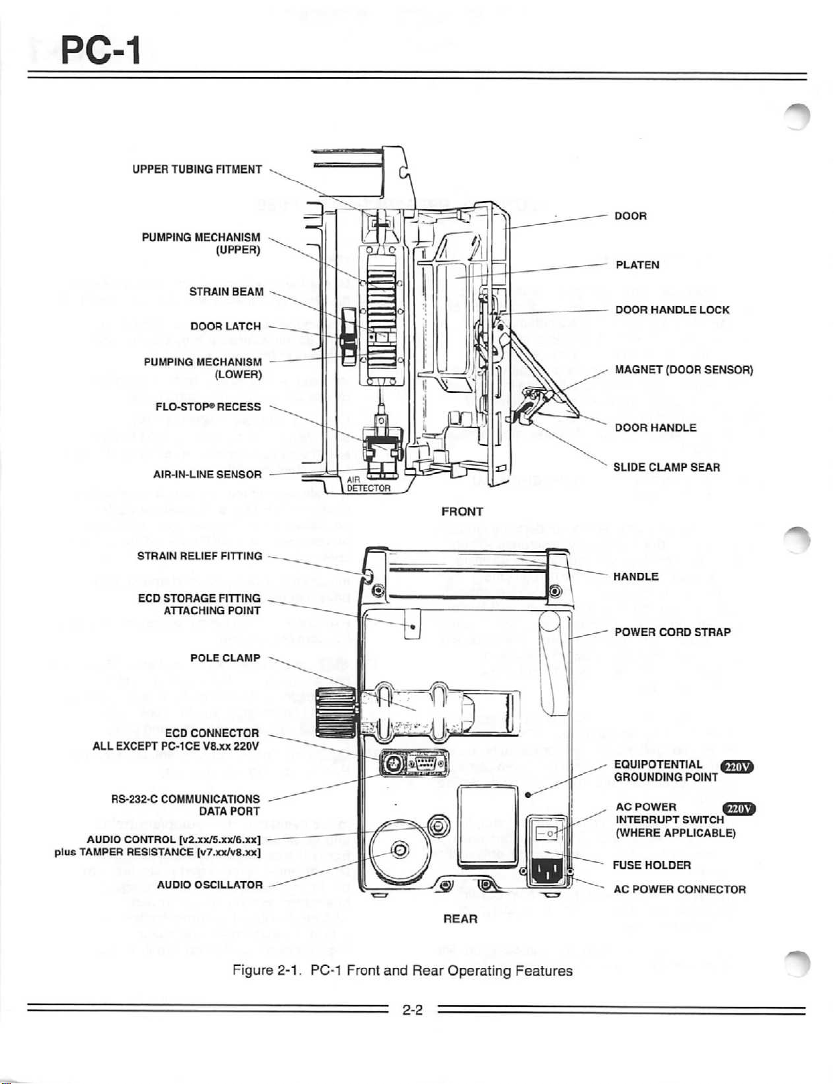
Figure 2-1. PC-1 Front
and
2-2
Rear
Operating
Features
EQUIPOTENTIAL
GROUNDING
AC
POWER
INTERRUPT
(WHERE
FUSE
AC
POWER
POINT
SWITCH
APPLICABLE)
HOLDER
CONNECTOR
#T7jT&
CETilfr
PC-1
f^
2.3
Prior to the first operational
routine
OPERATIONAL
PERFORMANCE
use
maintenanceorservicing of
pump/controller, it is strongly
operational
operational
phases;
check
compliance with regulatory
and
an Operational
proper
2.3.1
The
battery is fully
post
manufacturing quality
However,
between
operational battery
Connect
allow
2.3.2
The
pre-operational electrical inspection
an
electrical
check.
performance
performance
checkbeperformed.
check
a Pre-operational Electrical Inspection to
the
electrical integrity of
agency
Performance
pump/controller
Pre-operational
operation.
Check
charged
upon completion of
assurance
since
considerable
manufacture
and
first
chargeisrecommended.
the
AC
power
the
batterytocharge
Pre-operational
leakage
cordtoan
Electrical
test
and
for24hours.
CHECK
and
following
the
recommended
consistsoftwo
the
instrument for
any
PC-1
that
requirements
Test
to verify
Battery
Charge
inspection.
time could
elapse
use,apre
AC
outlet
and
Inspection
includes
a ground continuity
an
The
the
2.3.2.2
Performanelectrical
measurementincompliance
Care
125
between
and
exceed
2.3.3
The
designedtoensure
Electrical
Equipment
for Risk
the
the
grounding
100
Abbreviated
Test
following
Ground
and/or
Class
2G
grounding
pointonthe
milliohms.
operational
eachofthe
ground
CSA
Equipment.
pin on
Operational
pump/controller's controls
functioning properly,
all
the
features
modes.
2.3.3.1
The
supplies
performance
1. A GEMINI
Test
following
are
injection
Requirements
items
requiredtoconduct
tests:
site.
andtocheck
availableinthe
of laboratory equipment and
administration
(Example:
Test
impedance
with UL
Standard
The
the
power
rear
case
Performance
performance
PC-1
and
indicators is
the
normal operating
the
operational
set
withanupper
2210)
544
for Patient
C22.2 No.
impedance
cord plug
should not
test
is
operability of
0^
CAUTION
Someofthese
hazardous.
property
conducting
performed
2.3.2.1 Electrical
Perform an electrical leakage current
tests
Safeguards
should
such
by
qualified
Leakage
are
be
employed
tests.
inherently
for
personnel
Tests
should
personnel.
Test
and
when
only
measurement
in compliance with Underwriters Laboratories (UL)
544
for Patient
Standards
125 for Risk
currents
aretobe
Care
Equipment
Association (CSA)
Class
2G Equipment. Leakage
less
than
and/or
Standard
100
microamperes.
Canadian
C22.2
No.
be
2.
IV
Solution
3.
Standard
4.
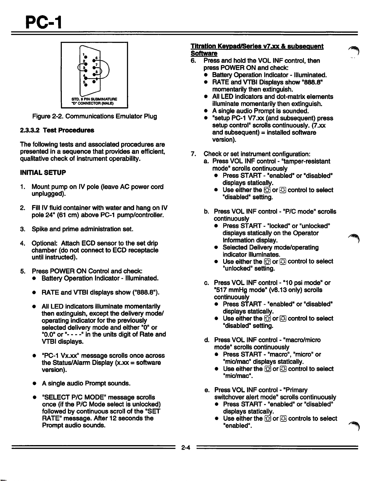
Communications
communications
2) [if
5.
Hemostat.
6. Empty fluid
7. Air-in-line
8. All
except
Container
Fractional
9.
Medical
ECD
or
Medical
Pressure
P/N
[use
Fractional
P/N
Container.
IV
Pole.
Emulator plug
container.
simulator
PC-1 CE
Detector
Keypad
10-1904-1
with
Titration
Keypad
10-1904-1
gaugeofat
(see
option is installed].
(see
Figure 2-3).
V8.xx
"A"
[use
PC-1s
Installed]
PC-1s
installed].
least
220V. Empty
with
without
Keypad
with
0-20
psig capability.
Figure 2-
Integer or
ALARIS
or Universal
and
Integer
ALARIS
2-3
PC-1
Figure 2-2.
2.3.3.2
The
Test
following
presented
qualitative
INITIAL
1. Mount
in a
check
SETUP
pump
STD.9PIN
-D- CONNECTOR (MALE)
Communications
Procedures
tests
sequence
of instrument operability.
onIVpole
and
SUBMINIATURE
Emulator
associated
that
(leave
procedures
providesanefficient,
AC
unplugged).
2.
Fill
IVfluid
pole 24" (61
3.
Spike
4. Optional: Attach ECD
chamber
until
5.
Press
container
cm)
above
and
prime administration
(do
not
connect
instructed).
POWER
ON
with
water
and
PC-1 pump/controller.
set.
sensortothe
to ECD
Control
and
receptacle
check:
• Battery Operation Indicator - Illuminated.
• RATE
• All LED
then
operating indicator for
selected
"0.0"
VTBI
• "PC-1 Vx.xx"
the
version).
• A
•
once
followed by
and
VTBI
displays
indicators
extinguish,
illuminate
except
the
delivery
or"
" in
mode
the
units digit of
displays.
message
scrolls
Status/Alarm Display (x.xx =
single
"SELECT
(if
audio
P/C
the
P/C
Prompt
MODE"
Mode
sounds.
message
select
continuous
RATE"
Prompt
message.
audio
sounds.
After12seconds
show
momentarily
the
delivery
previously
and
either
is unlocked)
scroll of
Plug
power
hang
set
drip
("888.8").
mode/
"0"
Rate
once
across
software
scrolls
the
"SET
the
are
cord
on IV
or
and
Titration
Software
6.
Keypad/Series
Press
press
and
hold
POWER
the
ON
v7.xx
VOL INF
and
check:
&
subsequent
control,
• Battery Operation Indicator - Illuminated.
and
• RATE
momentarily
• All
LED
VTBI Displays
then
indicators
extinguish.
and
illuminate momentarily
• A single
audio
Promptissounded.
• "setup PC-1 V7.xx (and
setup
control" scrolls continuously. (7.xx
and
subsequent)
= installed
show
dot-matrix
then
extinguish.
subsequent)
software
version).
7. Check or
a.
set
instrument configuration:
Press
VOL INF control - "tamper-resistant
mode" scrolls continuously
•
Press
START-"enabled"
displays
•
Use
either
statically.
the©or
(5)controltoselect
"disabled" setting.
b.
Press
VOL
INF
control-"P/C
continuously
•
Press
START-"locked"or"unlocked"
displays statically on
the
Operator
Information display.
Selected
•
indicator
•
Use
either
Delivery
illuminates.
the
mode/operating
® or © controltoselect
"unlocked" setting.
c.
Press
VOL INF control - "10 psi
"517 mmHg mode" (v8.13 only) scrolls
continuously
•
Press
START-"enabled"
displays
•
Use
either
statically.
the
fo)or(o) controltoselect
"disabled" setting.
d.
Press
VOL
INF
control-"macro/micro
mode" scrolls continuously
•
Press
START-"macro",
"micro"
"mic/mac" displays statically.
•
Use
either
the
(oj or © controltoselect
"mic/mac".
e.
Press
VOL INF control - "Primary
switchover
•
Press
displays
•
Use
"enabled".
alert
mode" scrolls
START-"enabled"
statically.
either
the
© or (o)
controlstoselect
then
"888.8"
elements
press
or
"disabled"
mode"
scrolls
mode"
or
"disabled"
or
continuously
or
"disabled"
or
2-4
PC-1
f.
Press
setup"
•
VOL
INF
scrolls
Press
START - "serial #"
control-"communications
continuously
displays
statically.
•
Use
controls
•
Press
displays
•
Use
baudrate
1,10,100
to input
PAUSE/STOP
statically.
either
and/or
the
(o)or© controltoselect
(110,
300,
CLEAR/SILENCE
serial
number.
-
"baudrate"
600,1200,
4800or9600).
Press
•
PAUSE/STOP
- "parity" displays
statically.
•
Use
either
the0or
© control to
parity option (O [odd], E [even]orOFF)
•
Press
g.
PAUSE/STOP
displays
•
Use
stop
Press
statically.
either
the
(o)or(o)
bit option (1or2).
VOL INF control - "language
- "stopbits"
controlstoselect
selection" scrolls continuously
Press
•
language
Use
•
language
french, italian,
Press
h.
START - currently
either
displays
the©or
statically.
option (english,
Swedish,
VOL INF control "exit
selected
© control to
german,
Spanish).
setup"
continuously.
i.
Press
infusion
•
•
STARTto exit
Setup
Battery
Rate
operation
and
and
VTBI
setup
Operation
LED
displays
and
flashes
show
enter
mode
2400,
select
select
scrolls
NORMAL
1.
2. Install
CONTROLLER
3.
4.
5.
MODE
Open
the
access
pumping
door.
is 24"
Press
Controller
mechanism
the
prepared
Ensure
above
the
P/C
mode:
• Controller
indicator
Press
RATE
•
Last
confirmed
rate
display.
"SET
•
Use
mL/hr.
•
RATE" scrolls continuously.
data
entry
New
rate
OCCLUSION
door
and
homes.
GEMINI
that
the
fluid
the
height of
MODE
MODE
mode
illuminates.
control
controltoselect
delivery mode/operating
and
rateor"0"
controls to
flashesinrate
check:
• "SET VTBI" scrolls continuously.
6.
Press
VTBI
control
•
Last
confirmed
and
check:
VTBIor"0"
VTBI display.
7.
Use
data
entry controls to
8.
Press
START
•
Pumping
• Controller
flashes.
•
VTBI
mechanism
mode
value
control
and
operating indicator
decrements
TESTS
check
levelinthe
the
set
that
set
and
strain
flashes
rateto125
display.
flashes
set
VTBI to50mL.
check:
operates.
~2
mL/minute.
the
close
container
beam.
in
the
in
the
the
CHARGING
1.
Connect
power
•
INDICATION (with PC-1
AC
AC
Power
source
Power
cordtoa
and
check:
Indicator-illuminates.
120or220
• Battery Operation Indicator - extinguishes.
2. Unplug AC
source
• AC
•
Six
[V2.XX/5.XX/6.XXupto
•
Battery
[v2.xx/5.xx/6.xxupto
flashes
3.
Reconnect
power
Power
and
check:
Power
Indicator - extinguishes.
pulsesofthe
operation
[v6.55/v7.xx
the
AC
source.
cord
audio
indicator
Power
from
the
Alarm -
6.55
6.55
and
subsequent].
cordtothe
ONLY].
- illuminates
ONLY] -
turned
AC
power
sound
AC
on)
VAC
2-5
9.
Use
the
hemostat
the
instrument
and
following conditions
upon
microprocessor
• "LOW FLOW" advisory -
• Audio
•
•
•
• Pumping
10.
Clear
and
press
•
•
•
"OCCLUDED"
Alarm
Operating
Alarm
advisory-sounds
Pumping
mechanism-stops
audio-sounds
mechanism-stops
occlusion (remove
allow
pump
to "home",
START,
Pumping
then
mechanism-operates.
indicator -
audio-silences.
to pinch off
check
the
for
oneofthe
tubing
(responseisdependent
timing
sequence):
scrolls
or
alarm
scrolls
hemostat),
close
open
door
check:
flashes.
above
door
and
PC-1
11.
Use
hemostattoclose
check*
• "LOW FLOW" advisory scrolls
• Advisory
• Pumping
12.
Within
advisory begins,
hemostat)
• Pumping mechanism -
• Operating indicator - flashes.
PUMP
13.
MODE
Press
modetoPump:
•
Pump
14.
Press
•
Pump
15.
Use
the
tubing
•
"OCCLUDED-FLUID
•
Pump
•
Alarm
• Pumping
16.
Clear
press
• Pumping
• Operating indicator -
17.
Use
the
and
check:
•
"OCCLUDED-PATIENT
scrolls
• Pump mode
•
Alarm
•
Pumping
18.
Clear
press
•
Pumping
•
Operating
19.
Remove
NORMAL
20.
Install
pump.
fluid
levelisabove
Close
operate
isinthe
audio-sounds
mechanism-stops.
45
seconds
after
clear
and
verify:
P/C
MODE control
mode
operating LED - illuminates.
START
control
mode
operating indicator - flashes.
hemostattoclose
and
check:
mode
ALARM
audio-sounds
mechanism-stops.
occlusion (remove hemostat),
START
and
check:
mechanism-operates
hemostattoclose
ALARM
audio-sounds
mechanism-stops.
occlusion (remove hemostat),
START
and
check:
mechanism-operates
indicator -
the
set
installed in
MODE
the
fluid
Press
the
door
normally,
air-in-line
TESTS.
filled
syringe
and
then
detector
off distal tubing
"LOW
FLOW"
occlusion (remove
operates
and
change
and
check:
off
the
proximal
SIDE"
alarm-scrolls
indicator - flashes
flashes.
off
the
distal tubing
SIDE"
alarm
indicator - flashes
flashes.
step2under
air-in-line
simulator
plungertoensure
the
air-in-line
press
START.
detector.
Pump
extract plunger until air
and
check:
and
delivery
then
-
then
in
the
the
will
•
"AIRINLINE"
•
Pump
•
Alarm
•
Pumping
21. Upon
simulator
PUMP
1.
PRESSURE
Power
initialize
Diagnostic
COMPUTER
Then
2.
Connect
gauge.
3.
Press
switch to
4.
Press
5. Verify
6.
Press
operate
the
7.
Record
Resultant
Software
subsequent
COMMUNICATIONS
1.
Connect
the
2. Initialize
mode
audio-sounds
test
completion,
and
down
instrument
Mode.
press
POWER
the
distal tubingtothe
COMPUTER
select
START
rate
setto125
START
foratleast30seconds
peak
pressure
the
highest
pressure
Release
the
RS-232-C
the
PC-1 pump/controller in
Maintenance/Diagnostic
procedure).
for
•
"Maintenance
and
subsequent",
STOP"
messages
software
3.
Press
control6times
• "serial
COMPUTER
port
continuously.
4.
Press
START
• "echo"
message
alarm-scrolls
ALARM
indicator-flashes
mechanism-stops.
remove
re-install
TEST
the
set
PC-1
pump/controller
in
the
Press
CONTROL/MONITOR
the
removedinstep
Maintenance/
and
hold
ON.
pressure
CONTROL/MONITOR
"pump test".
control
control
twice.
mL/hr
and
and
allow
VTBI
the
and
stabilizes.
pressure
must
V6.xx
Instruments
Communications
Data
Port.
be
Mode
reading
*17
Emulator
(see
Vx.xx"or"Diagnostic Vx.xx
and
To
Exit
scroll, (x.xx = installed
release).
CONTROL/MONITOR
and
check:
test"
control
message
and
displays
scrolls
check:
statically
air-in-line
and
the
switch.
>25
pump
wait until
obtained.
psi.
&
Plug to
the
Section
Press
2.
re
mL.
to
5
2-6
PC-1
or
5.
6.
7.
•"««"-
displays statically in
information display
the
VTBI
display.
Press
COMPUTER
control
Vx.xx"
[v7.xx
Press
Maintenance
instrument.
Remove
from
twicetoreturntothe
[v2.xx/5.xx/6.xx]or"Diagnostic Vx.xx"
and
subsequent]
PAUSE/STOP
Mode
the
Communications
the
RS-232-C
the
and
"PLUG"
CONTROL/MONITOR
"Maintenance
appears
message.
controltoexit
and
power
the
down
Emulator Plug
Data
Port.
operator
in
the
2-7
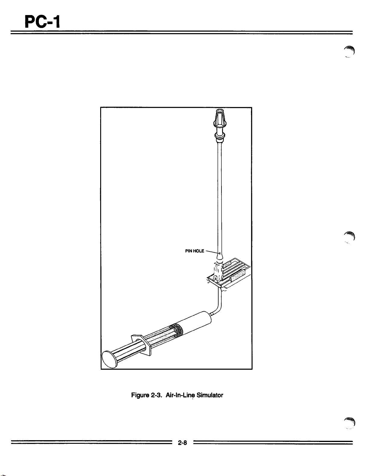
PC-1
/^|s.
Figure
2-3.
Air-ln-Line Simulator
/^*v
2-8
 Loading...