

IMCO Xtreme Advantage scX-sc, SCX, SCX4 Service Manual

IMCO SCX SERIES INFORMATION, OPERATION & MAINTAINANCE
1. SCX & SCX4 Drives will not fit on a standard gimbal helmet, IMCO HELMET:
#05-8025 Black or #05-8027 Silver or #05-8028 ITS Black is required.
2. Maximum engine idle speed is 800 RPM. Shift drive with a positive move, do not let
clutch sit between neutral and in gear position.
3. Do Not
install propeller until the drive shift linkage has been properly installed and
tested with the engine running!
4. When using SCX or SCX4 drives it is necessary to have full hydraulic steering for
your safety.
5. When tuning engine remove propeller and shift drive into forward gear!
6. Do not run your boat with a worn or loose gimble ring or helmet, worn clevis pins, or clevis bushings.
7. Every hull is different and requires a different setup: Many different things contribute to performance:
water pickup location, cavitation plates, gear ratio, drive height, prop, weight distribution, water conditions,
weather conditions.
8. If you are installing the drive on a new application, consult the manufacture or a dealer with experience
with the hull to determine the proper drive height.
9. SCX Drive is 19 7/8” from crankshaft center line to prop shaft center line (2” shorter than standard Bravo).
SCX4 Drive is 17 7/8” from crankshaft center line to propshaft center line (4” shorter than standard Bravo).
10. The bolt pattern is different from the SCX to the SCX4, lowers cannot be interchanged.
11. Max propeller diameter on the SCX is 16 3/4”, SCX4 is 17” (always check that there
is at least 1/2” clearance between the propeller blades and the drive case.
12. Large diameter propellers installed on a #6 prop shaft will require a torque tab on single engine boats.
13. SCX and SCX4 drives require a drive oil reservoir with a minimum capacity of 1 1/2 quarts.
14. When installing drive to gimbal or lower to upper always use anti-seize on all threads
15. When installing lower to upper, inspect all “O” rings, replace as necessary, pressure check to insure
proper seal.
16. If you do your own maintenance and repairs on your IMCO drive, you will need a service manual and the
proper tools. Service manuals and tools are available at www.imcomarine.com/cal_store.
17. Always wear proper safety equipment when operating your boat, testing or running at high speeds.
18. Inspect for: oil level in drive and reservoir, leaks, loose fasteners, worn parts.
Warning!
Warning!
Warning!
Danger!
Warning!
Warning!
Before Runnng!
Recommended oil: Torco RTF GL-6 (Torco Part #A220015CE (unit) Part # S220015C (case) IMCO Part #
09-2600 (unit) Part # 09-2605 (5 Gal.) Part # 09-2610 (case) (100% Synthetic Raceing Transmission Fluid)
Replaces SAE 75W90.
To drain oil: remove drain screws from bearing carrier (right below the prop shaft) and on port side of upper.
To replace oil: pump oil in from lower drain screw until it comes out of upper drain screw hole. Replace drain
screws and add oil to drive oil reservoir.
When changing oil, run the used oil through a strainer to check for metal particles, if ther are metal
particles in the oil it is time for inspection of the gears and bearings. If oil appears milky or off colored check
for leaks.
SCX, SCX4 capacity: 5 qts + reservoir - SCX Upper with SC Lower 4 1/2 qts + reservoir.
19. Drive must be turning before shifting.
20. Do not run engine when drive is trimmed extremely high, or in trailer tow mode.
21. Do not use solvents or chemical cleaners to clean painted surfaces on the drive.
22. When installing or changing propeller use extreme caution, propeller blades can
be very sharp.
23. SCX upper vertical shaft is 17 tooth spline, SC, Merc lowers are 15 tooth spline. A 17-15 tooth
coupler is available 01-2150 (cannot be used with a spacer).
24. Use extreme caution if modifying lower, case can be weakened or handling can
be adversely affected.
25. Break in: Do not use full throttle until drive is fully warmed up, do not hold drive at wide open throttle for
more than 2 minutes for the first 3 hours of use.
26. Inspect anode (located on front of cavitation plate) for corrosion or debris; if necessary clean or replace.
27. Do not shift drive while running on hose with
propeller installed.
28. Rotation: shift linkage pushed in - right hand rotation, shift
linkage pulled out - left hand rotation.
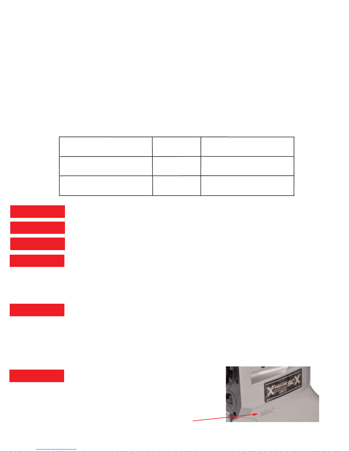
29. Serial # location: Port side below SCX, SCX4 sticker
3/10/14
SCX Upper & SCX Lower
New Break in
20 hours
After Break In
80 hours
SCX4 Upper & SCX4 Lower
New Break in
20 hours
New Break in
20 hours
SCX Upper & SC Lower
After Break In
80 hours
Check Drain Plug Magnet
Every 20 Hours
Warning!
Warning!
Caution!
Danger!
Caution!
Caution!

X
X
XTREME
ADVANTAGE
sc
sc
X-
X-
sc
sc
Parts and Service Manual
IMCO
510 East Arrow Highway
San Dimas, CA 91773
(800) 899-8058 (909) 592-6162 Fax (909) 592-6052
www.imcomarine.com email info@imcomarine.com

TABLE OF CONTENTS
Upper Gear Case - Disassembly 1
Upper Case Hardware & Seals (Drawing) 2
Upper Case Hardware & Seals (Parts List) 3
Upper Case Gear & Components (Drawing) 4
Upper Case Gear & Components (Parts List) 5
Upper Gear Case Assembly 6
Upper Gear Case Assembly Cont. 7
SCX Setup Diagrams 8
SCX Setup Work Sheet 9
Backlash Assembly (Diagram) 10
Lower Gear Case-Disassembly 11
Lower Gear Case (Drawing) 12
Lower Gear Case (Parts List) 13
Lower Gear Case-Assembly 14
Lower Pinion Height Measurments 15
Dissassembly-Assembly Tools 16
02/15/10 Rev 1
Serial Number
Date of Purchase
Purchased From
Check Oil Before Running
First break in oil change 5-8 hours.
Oil is filled to upper drain screw [Fig 1-33]
Pump oil from bottom drain screw [Fig 6-32]
Recommended oil change intervals 20-30 hours.
Heavy use or high HP change more often.

UPPER GEAR CASE-DISASSEMBLY
NOTE; The following instructions assume that the drive has been removed from the
transom assembly and is shifted to the “neutral” position. The lower unit has also been
removed, along with the yoke coupler end, center socket, and cross and bearings. Steps
followed by asterisk (**) are required only if inspection indicates component replacement.
Brackets following the part name represent the drawing figure # and item #.
1. Remove upper cap screws [1-7,8], remove upper cap [1-3].
2. Remove steering cap screws [1-28], remove steering cap [1-2 ]
3. Remove detent kit from steering cap [1-31].
4. Remove cotter key [2-23].
5. Remove shift link [2-24], shift cable retainer [2-21], shift arm [2-22]. (Shift link
removes out front of gear case).**
6. Remove shift shaf t screws [2-27].
7. Remove shift shaft plug [1-9], shift shaft [2-26], yoke & cam [2-28].
8. Remove pinion hub screws [1-(22,23)].
9. Remove pinion hub assembly [2-(31-45)].
10. Disassemble pinion hub assembly.
11. Remove yoke nut [2-36], and washer [2-37].
12. Remove yoke [2-32].
13. Remove retainer nut [2-31].
14. Remove Yoke gear end shims [2-42], pinion shoulder washer [2-43], and pinion
seal carrier [2-45].
15. Remove bearings [2-(38,41)], bearing cups [2-(39,40)], and pinion gear [2-12].
Note; be sure to maintain correct assembly position of the upper & lower thrust
bearings & races.
16. Remove upper thrust race [2-6], and upper thrust bearing [2-7].
17. Remove gear assembly [2-(7-17)].
18. Disassemble gear assembly, press down on upper clutch gear to release the
clutch shaft retainer keepers and remove all components from the clutch shaft.
19. Remove lower thrust race [2-6], lower thrust bearing [2-7].
20. Remove oil tank cover [1-43], in spect magnet [1-40].
Page 1
Page 2
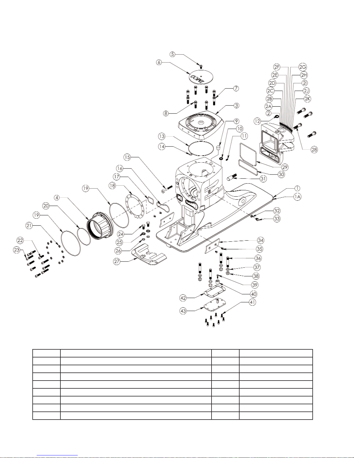
Upper Case Hardware & Seals
Fig-1
Item Des c ription Qty Part Number
1 Upper Case Black 1 01-1550
1A Upper Case Silver 1 01-1557
2 Steer in g Cap CA Black 1 01-1551
2A Steer in g Cap NV Black 1 01-1552
2B Steer in g Cap Generic Black 1 01-1553
2C Steer in g Cap ITS Black 1 01-1554
2D Steer in g Cap Tie Bar Starboard Black 1 01-1555
2E Steering Cap Tie Bar Port Black 1 01-1556
 Loading...