

IMCO Xtreme Advantage Parts And Service Manual
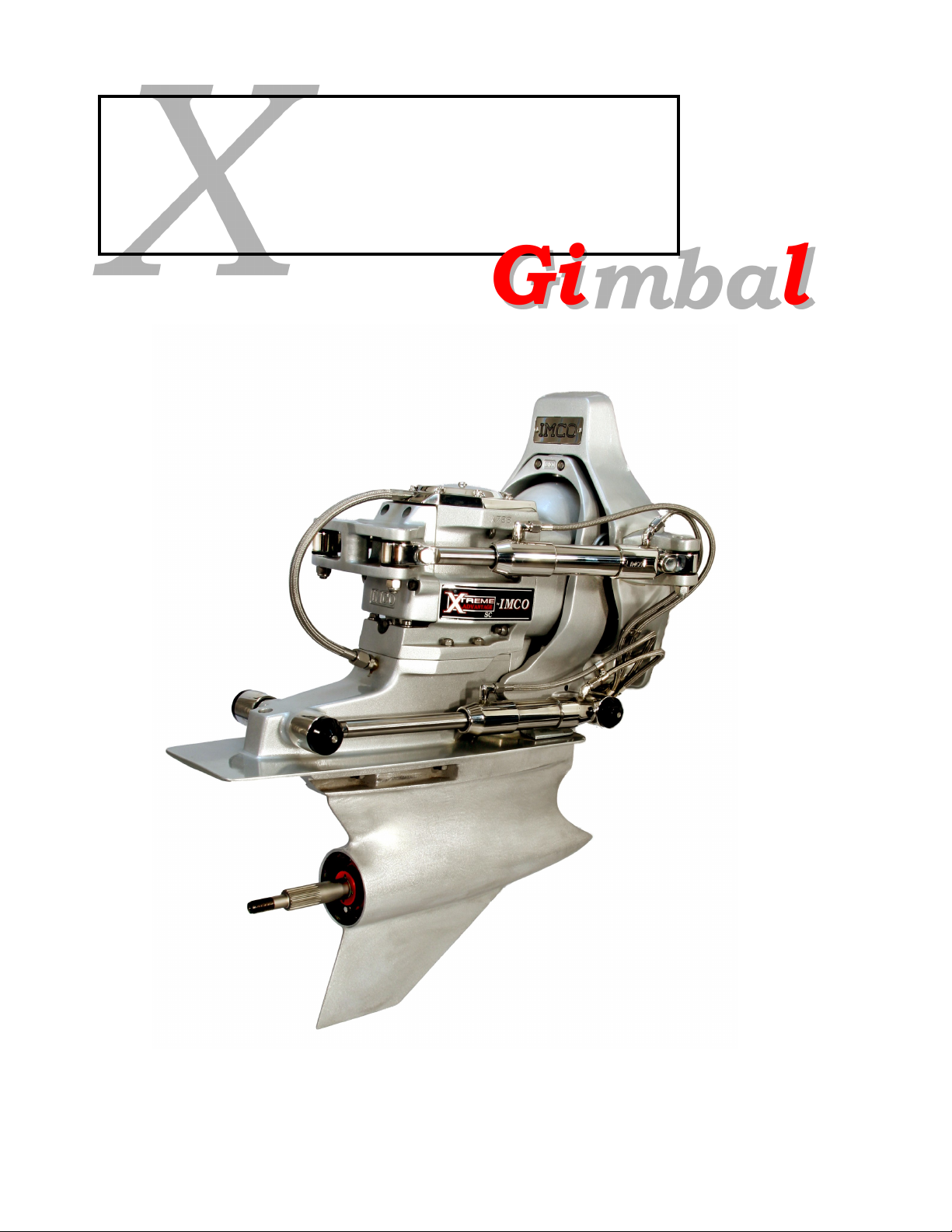
Gimbal
X
XTREME
ADVANTAGE
Parts and Service Manual
IMCO
510 East Arrow Highway
San Dimas, CA 91773
(800) 899-8058 (909) 592-6162 Fax (909) 592-6052
www.imcomarine.com email info@imcomarine.com

TABLE OF CONTENTS
Cutting Transom, Gimbal Installation, Trim Pump Hose Hookup ...………………………………………… 1
Drive Oil Reservoir Tank, Water Supply Fitting ………………………………………………………………. 2
Rear Engine Mount, Shift Cable Adjustment, Steering Hose Hookup ……………………………………… 3
Gimbal Housing (Drawing) …………...…………………………………………………………….…………… 4
Gimbal Housing (Parts List) ………………... ………………………………………………………………….. 5
Gimbal Ring (Drawing) …….…………………………………………………………………………………….. 6
Gimbal Ring (Parts List) …………...……………………………………………………………………………. 7
Gimbal Helmet (Drawing) ..……………………………………………………………………………………... 8
Gimbal Helmet (Parts List) ...…………………………………………………………………………………… 9
Gimbal Steering & Trim (Drawing) …………………………………………………………………………….. 10
Gimbal Steering & Trim (Parts List) ..…………………………………………………………………….……. 11
Serial Number
Date of Purchase
Purchased From
10-17-19 Rev 4
Cutting Transom
1. Using the provided template or using the Bravo Drilling fixture that can be purchased through a Mercury
MerCruiser Dealer can determine the transom cutout size. (Angle holes for tiller arm are not necessary
with Xtreme Advantage Gimbals).
2. Propeller height or crankshaft centerline is best determined by the hull manufacture or by previous testing.
3. Transom thickness must be between 2” and 2 ¼”.
Xtreme Advantage Gimbal Installation
1. Remove gimbal from shipping carton and remove plywood backing plate.
2. Remove all packing materials, retain steering ram restraints. (Do not allow steering rams to damage paint-
ed surfaces.)
3. Position gimbal housing onto transom and hold in place.
4. Secure inner and outer transom pieces together with 8-7/16 washers and 8-7/16 nylock nuts provided.
5. Tighten fasteners in small increments in a criss cross pattern to 23 ft lbs.
IMPORTANT: When installing gimbal to IMCO extension box the two upper studs
need to be 2 ¾” for EB-12-N and EB-12-3 and 2 ¼” for EB-14-T extension box’s.
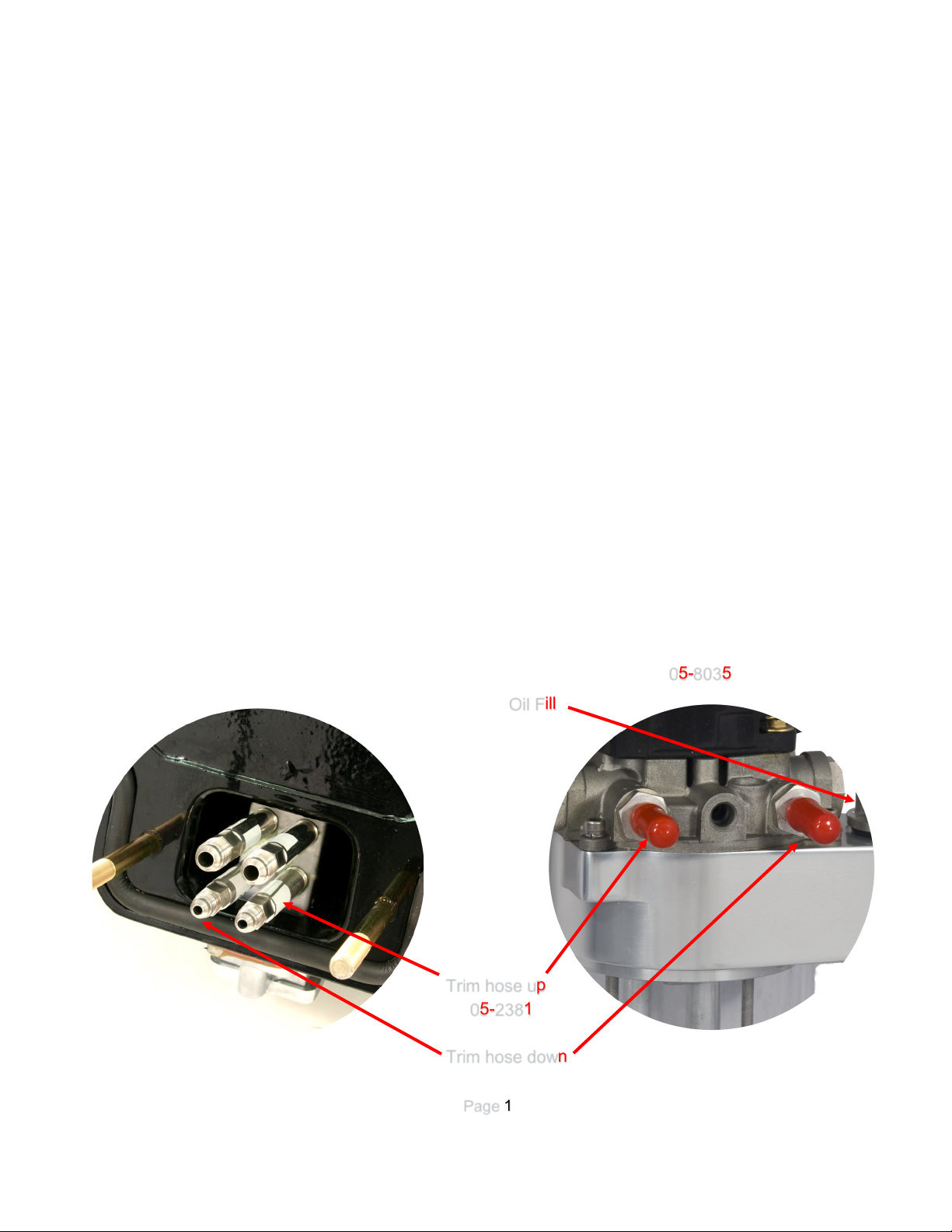
Trim Pump Hose Hookup
1. Use provided hoses to hookup trim pump as pictured below.
2. Fill oil through oil fill cap as shown.
05-8035
Trim hose up
05-2381
Trim hose down
Page 1
Oil Fill

Drive Oil Reservoir
1. Install water supply fitting with bolts and lock washers provided.
(Torque bolts to 45 in lbs).
2. Install optional water block off plate with bolts and lock washers pro-
vided. (Torque bolts to 45 in lbs).
CAUTION: When using optional block off plate provisions for water
flow through the drive is mandatory for drive cooling.
a. Remove or cut water supply hose in gimbal.
b. Route water to external water dump.
Oil hose connection
1. Connect the gimbal housing and drive oil reservoir tank together with
the hose and fitting provided.
IMPORTANT: Drive oil reservoir must be installed higher than the
oil fitting on gimbal. Run hose as straight as possible to avoid a low
section in the system.
2. Hose must be routed away from rotating shaft.
CAUTION: Do not over fill drive oil reservoir!
Drive Oil Reservoir
05-2013
05-2382
Page 2
 Loading...