


IMCO SCX SERIES INFORMATION, OPERATION & MAINTAINANCE
1. SCX & SCX4 Drives will not fit on a standard gimbal helmet, IMCO HELMET:
#05-8025 Black or #05-8027 Silver or #05-8028 ITS Black is required.
2. Maximum engine idle speed is 800 RPM. Shift drive with a positive move, do not let
clutch sit between neutral and in gear position.
3. Do Not
install propeller until the drive shift linkage has been properly installed and
tested with the engine running!
4. When using SCX or SCX4 drives it is necessary to have full hydraulic steering for
your safety.
5. When tuning engine remove propeller and shift drive into forward gear!
6. Do not run your boat with a worn or loose gimble ring or helmet, worn clevis pins, or clevis bushings.
7. Every hull is different and requires a different setup: Many different things contribute to performance:
water pickup location, cavitation plates, gear ratio, drive height, prop, weight distribution, water conditions,
weather conditions.
8. If you are installing the drive on a new application, consult the manufacture or a dealer with experience
with the hull to determine the proper drive height.
9. SCX Drive is 19 7/8” from crankshaft center line to prop shaft center line (2” shorter than standard Bravo).
SCX4 Drive is 17 7/8” from crankshaft center line to propshaft center line (4” shorter than standard Bravo).
10. The bolt pattern is different from the SCX to the SCX4, lowers cannot be interchanged.
11. Max propeller diameter on the SCX is 16 3/4”, SCX4 is 17” (always check that there
is at least 1/2” clearance between the propeller blades and the drive case.
12. Large diameter propellers installed on a #6 prop shaft will require a torque tab on single engine boats.
13. SCX and SCX4 drives require a drive oil reservoir with a minimum capacity of 1 1/2 quarts.
14. When installing drive to gimbal or lower to upper always use anti-seize on all threads
15. When installing lower to upper, inspect all “O” rings, replace as necessary, pressure check to insure
proper seal.
16. If you do your own maintenance and repairs on your IMCO drive, you will need a service manual and the
proper tools. Service manuals and tools are available at www.imcomarine.com/cal_store.
17. Always wear proper safety equipment when operating your boat, testing or running at high speeds.
18. Inspect for: oil level in drive and reservoir, leaks, loose fasteners, worn parts.
Warning!
Warning!
Warning!
Danger!
Warning!
Warning!
Before Runnng!
Recommended oil: Torco RTF GL-6 (Torco Part #A220015CE (unit) Part # S220015C (case) IMCO Part #
09-2600 (unit) Part # 09-2605 (5 Gal.) Part # 09-2610 (case) (100% Synthetic Raceing Transmission Fluid)
Replaces SAE 75W90.
To drain oil: remove drain screws from bearing carrier (right below the prop shaft) and on port side of upper.
To replace oil: pump oil in from lower drain screw until it comes out of upper drain screw hole. Replace drain
screws and add oil to drive oil reservoir.
When changing oil, run the used oil through a strainer to check for metal particles, if ther are metal
particles in the oil it is time for inspection of the gears and bearings. If oil appears milky or off colored check
for leaks.
SCX, SCX4 capacity: 5 qts + reservoir - SCX Upper with SC Lower 4 1/2 qts + reservoir.
19. Drive must be turning before shifting.
20. Do not run engine when drive is trimmed extremely high, or in trailer tow mode.
21. Do not use solvents or chemical cleaners to clean painted surfaces on the drive.
22. When installing or changing propeller use extreme caution, propeller blades can
be very sharp.
23. SCX upper vertical shaft is 17 tooth spline, SC, Merc lowers are 15 tooth spline. A 17-15 tooth
coupler is available 01-2150 (cannot be used with a spacer).
24. Use extreme caution if modifying lower, case can be weakened or handling can
be adversely affected.
25. Break in: Do not use full throttle until drive is fully warmed up, do not hold drive at wide open throttle for
more than 2 minutes for the first 3 hours of use.
26. Inspect anode (located on front of cavitation plate) for corrosion or debris; if necessary clean or replace.
27. Do not shift drive while running on hose with
propeller installed.
28. Rotation: shift linkage pushed in - right hand rotation, shift
linkage pulled out - left hand rotation.
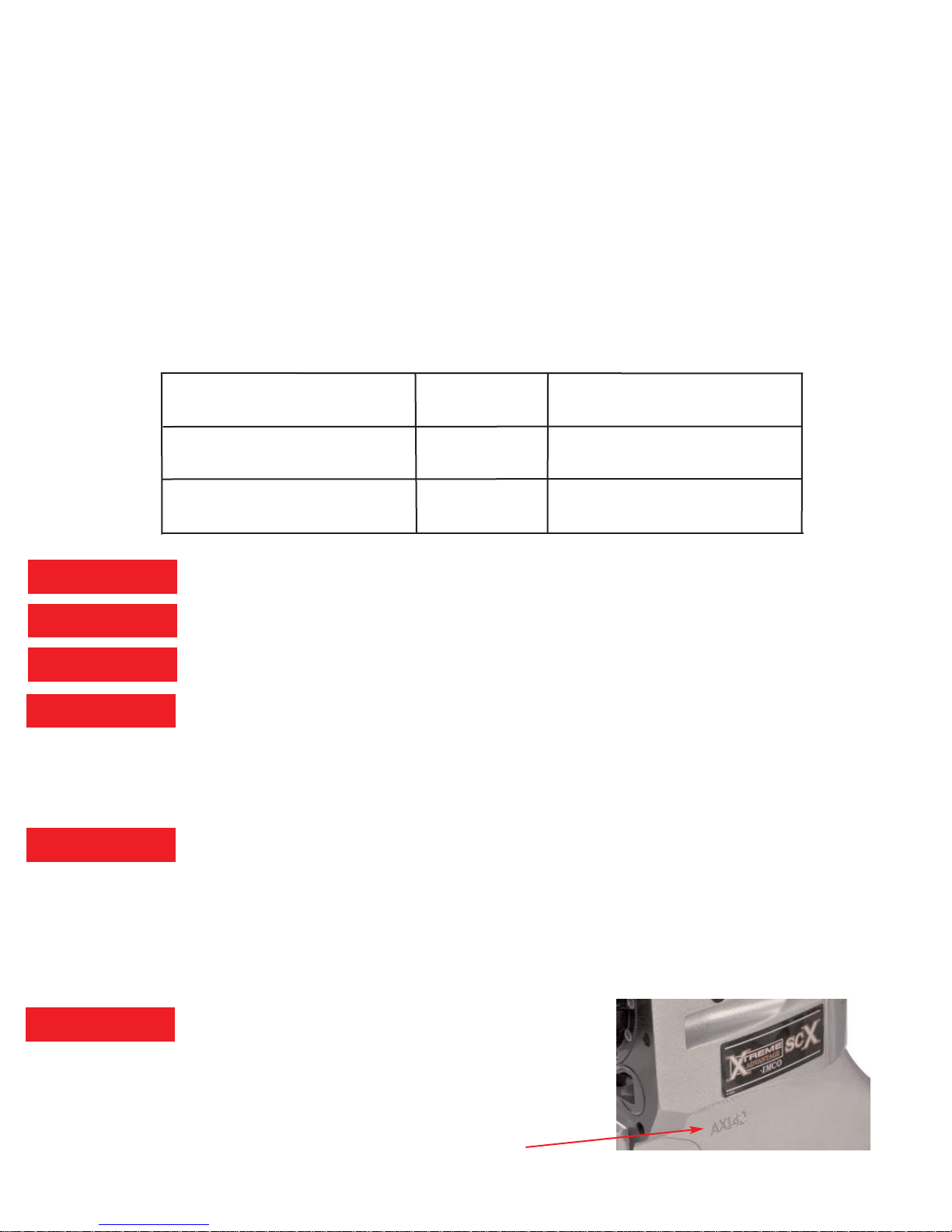
29. Serial # location: Port side below SCX, SCX4 sticker
3/10/14
SCX Upper & SCX Lower
New Break in
20 hours
After Break In
80 hours
SCX4 Upper & SCX4 Lower
New Break in
20 hours
New Break in
20 hours
SCX Upper & SC Lower
After Break In
80 hours
Check Drain Plug Magnet
Every 20 Hours
Warning!
Warning!
Caution!
Danger!
Caution!
Caution!

X
X
XTREME
ADVANTAGE
sc
sc
X-
X-
sc
sc
Parts and Service Manual
IMCO
510 East Arrow Highway
San Dimas, CA 91773
(800) 899-8058 (909) 592-6162 Fax (909) 592-6052
www.imcomarine.com email info@imcomarine.com

TABLE OF CONTENTS
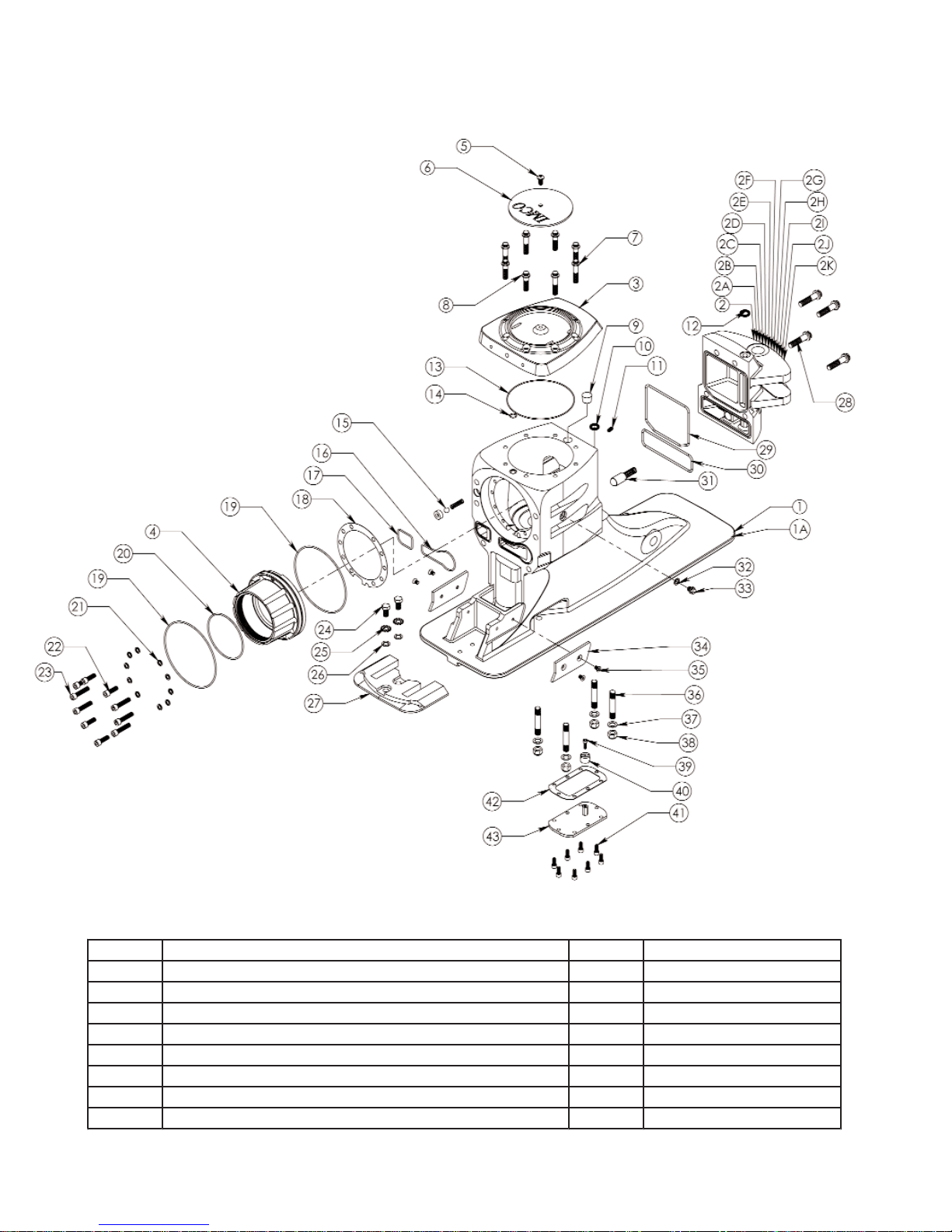
Upper Gear Case - Disassembly 1
Upper Case Hardware & Seals (Drawing) 2
Upper Case Hardware & Seals (Parts List) 3
Upper Case Gear & Components (Drawing) 4
Upper Case Gear & Components (Parts List) 5
Upper Gear Case Assembly 6
Upper Gear Case Assembly Cont. 7
SCX Setup Diagrams 8
SCX Setup Work Sheet 9
Backlash Assembly (Diagram) 10
Lower Gear Case-Disassembly 11
Lower Gear Case (Drawing) 12
Lower Gear Case (Parts List) 13
Lower Gear Case-Assembly 14
Lower Pinion Height Measurments 15
Dissassembly-Assembly Tools 16
02/15/10 Rev 1
Serial Number
Date of Purchase
Purchased From
Check Oil Before Running
First break in oil change 5-8 hours.
Oil is filled to upper drain screw [Fig 1-33]
Pump oil from bottom drain screw [Fig 6-32]
Recommended oil change intervals 20-30 hours.
Heavy use or high HP change more often.

UPPER GEAR CASE-DISASSEMBLY
NOTE; The following instructions assume that the drive has been removed from the
transom assembly and is shifted to the “neutral” position. The lower unit has also been
removed, along with the yoke coupler end, center socket, and cross and bearings. Steps
followed by asterisk (**) are required only if inspection indicates component replacement.
Brackets following the part name represent the drawing figure # and item #.
1. Remove upper cap screws [1-7,8], remove upper cap [1-3].
2. Remove steering cap screws [1-28], remove steering cap [1-2 ]
3. Remove detent kit from steering cap [1-31].
4. Remove cotter key [2-23].
5. Remove shift link [2-24], shift cable retainer [2-21], shift arm [2-22]. (Shift link
removes out front of gear case).**
6. Remove shift shaf t screws [2-27].
7. Remove shift shaft plug [1-9], shift shaft [2-26], yoke & cam [2-28].
8. Remove pinion hub screws [1-(22,23)].
9. Remove pinion hub assembly [2-(31-45)].
10. Disassemble pinion hub assembly.
11. Remove yoke nut [2-36], and washer [2-37].
12. Remove yoke [2-32].
13. Remove retainer nut [2-31].
14. Remove Yoke gear end shims [2-42], pinion shoulder washer [2-43], and pinion
seal carrier [2-45].
15. Remove bearings [2-(38,41)], bearing cups [2-(39,40)], and pinion gear [2-12].
Note; be sure to maintain correct assembly position of the upper & lower thrust
bearings & races.
16. Remove upper thrust race [2-6], and upper thrust bearing [2-7].
17. Remove gear assembly [2-(7-17)].
18. Disassemble gear assembly, press down on upper clutch gear to release the
clutch shaft retainer keepers and remove all components from the clutch shaft.
19. Remove lower thrust race [2-6], lower thrust bearing [2-7].
20. Remove oil tank cover [1-43], in spect magnet [1-40].
Page 1
Page 2
Upper Case Hardware & Seals
Fig-1
Item Des c ription Qty Part Number
1 Upper Case Black 1 01-1550
1A Upper Case Silver 1 01-1557
2 Steer in g Cap CA Black 1 01-1551
2A Steer in g Cap NV Black 1 01-1552
2B Steer in g Cap Generic Black 1 01-1553
2C Steer in g Cap ITS Black 1 01-1554
2D Steer in g Cap Tie Bar Starboard Black 1 01-1555
2E Steering Cap Tie Bar Port Black 1 01-1556

Page 3
Upper Case Hardware & Seals
Fig-1
Item Des c ription Qty Part Number
2F Steer in g Cap CA Silver 1 01-1558
2G Steering Cap NV Silver 1 01-1559
2H Steer in g Cap Generic Silver 1 01-1560
2I Steer in g Cap ITS Silver 1 01-1561
2J Steering Cap Tie Bar Starboard Silver 1 01-1562
2K Steer in g Cap Tie Bar Port Silver 1 01-1563
3 Upper Cap 1 01-2555
4 Pinion Hub 1 01-2560
5 Screw (5/16-18 x 1/2" But t on He ad) 1 08-040705041
6 Top Cap Lid 1 01-2071
7 Screw (3/8-16 x 1 3/4" S/S 12 Point) 4 08-070806111
8 Screw (3/8-16 x 1 1/2" S/S 12 Point 4 08-070806101
9 Shift Shaft Plug 1 11-1024
10 Quad Ring (Cooling Water, Bottom) 1 11-4024
11 Screw (5/16-18 x 1/2" Allen Set)(Tower Retainer) 1 08-050705041
12 Quad Ring (Cooling Water, Top) 1 11-4025
13 "O" Ring (Top Cap) 1 11-2049
14 "O" Ring (Top Cap Oil Pressu re) 1 11-2013
15 Spring Kit (Seal,Ball & Spring) Kit 01-2045
16 "O" Ring (Water Passage- Upper to Gimbal) 1 11-2148
17 "O" Ring (Shift Linkage) 1 11-2129
18 Pinion Hub Shims Kit 01-2548
19 "O" Ring (Pinion Hub) 2 11-2161
20 "O" Ring (Pinion Retain er Nut) 1 11-2154
21 Pinion Hub (5/16" Copper Sealing Washe r s) 10 08-120700004
22 Screw (5/16-18 x 1" Socket Cap) 4 08-060705082
23 Screw (5/16-18 x 1 1/2" Socket Cap) 6 08-060705102
24 Screw (3/8-16 x 3/4" HH) 2 08-010806061
25 Washer ( 3/8" Star) 2 08-110800001
26 Washer ( 3/8" AN) 2 08-100800001
27 Anode 1 01-2067
28 Screw (7/16-14 x 1 3/4" S/S 12 Po in t ) 4 08-070907111
29 "O" Ring (Steerin g Cap, Oil) 1 11-2250
30 "O" Ring (Steering Cap, Shift Cavity) 1 11-2242
31 Detent Kit (Spring & Ball Cylinde r) Kit 01-2044
32 Drain Screw Sealing Washer 1 11-1017
33 Drain Screw 1 01-2504
34 Guide Pads (Port & Starbo ard) 2 01-2471
35 Screw (1/4-20 x 1/2" Flat Head Undercut) 4 08-020604041
36 Stud (7/16 x 2 1/2") 4 08-130904141
37 Washer ( 7/16" AN S/S) 4 08-100900001
38 Nut (7/16-20 Nylock S/S) 4 08-080904001
39 Screw (10-24 x 5/8" Socket Cap) 1 08-060403052
40 M ag n et 1 01-9587
41 Screw (1/4-20x 5/8" Socket Cap) 8 08-060604051
42 Oil Tank Gasket 1 11-1030
43 Oil Ta nk Cover 1 01-2574

Page 4
Upper Case Gear & Components
Fig-2

Item Des c ription Qty Part Number
1 Upper Case Black 1 01-1550
1A Upper Case Silver 1 01-1557
2 Roller Bearing (Clutch Shaft Cap) 1 10-3042
3 Upper Cap 1 01-2555
4 Pinion Hub 1 01-2560
5 Tower Race 2 10-6041
6 Thrust Race 2 10-5045-X
7 Thrust Bearing (Gear ) 2 10-4044
8 Keep ers (Clutch Shaft) 2 01-2047
9 Clutch Shaft Ret ain er (Thrust Collar) 1 01-2189
10 Spirol Retainer Ring 2 01-2055
11 Roller Bearin g (Internal Gear) 2 10-3046
12 SCX Pinion Ge ar 1 01-4538
13 SCX Clutch Gear 2 01-4539
14 Thrust Bearing (Clutch Spring) 2 10-4020
15 Clutch Spring 2 01-2056
16 SCX Clutch 1 01-2562
17 SCX Clutch Shaft 1 01-3556
18 Pinion Hub Shims Kit 01-2548-X
19 Roller Bearin g (Clutch Shaft Tower) 1 10-3043
20 SCX Tower 1 01-2561
21 SCX Shift Cable Retainer 1 01-2573
22 SCX Shift Arm 1 01-1578
23 Cotte r Key 1 08-150200141
24 SCX Shift Link 1 01-1577
25 Shift Shaft Bushing 1 10-7018
26 SCX Shift Shaft 1 01-3559
27 Screw (1/4-28 x 3/4" Socket Cap) 2 08-060602062
28 Yoke & Cam 1 01-8095
29 Seal, Shift Shaft 2 11-3030
30 Shift Shaft Bushing 1 10-7019
31 Retainer Nut 1 01-2239
32 Yoke Gear End 1 01-2085
33 Cross & Bearing 2 01-2086
34 Center Socket 1 01-2087
35 Yoke Coupler End 1 01-2088
36 Nut (Yoke Gear End) ( 5/8-18 Thin Nylock Steel) 1 08-091105002
37 Washer ( Yoke Gear End) 1 08-121100002
38 Bearin g Cone (Pinion Be aring) 1 10-1021
39 Bearin g Cup (Pinion Be aring) 1 10-2022
40 Bearin g Cup (Pinion Be aring) 1 10-2024
41 Bearin g Cone (Pinion Be aring) 1 10-1023
42 Yoke Gear End Shims Kit 01-2020- X
43 Pinion Shoulder Washer 1 01-2241
44 Yoke Gear End Seal 1 11-3029
45 Pinion Seal Carrier 1 01-2240
Page 5
Upper Case Gear & Components
Fig-2

UPPER GEAR CASE-ASSEMBLY
NOTE; Optimum performance of the upper gear case requires “setting up” the pinion &
clutch gears with IMCO procedure as follows.
1. Take all measurements using the “SCX Setup Dia grams” (Fig 3) and the “SCX
Work Sheet” (Fig 4).
2. After all measurements are taken and proper race thickness has been
determined, place lower race [2-6] and thrust bearing [2-7] in case.
3. Place lower clutch gear [2-13] with attached tool (backlash tower 01-5579) into
case.
4. Adjust rolling preload (8-10 in/lbs) on pinion gear by changing Yo ke Gear End
Shims [2-42]. Tighten nut [2-36] to 75 ft/lbs.
5. After proper rolling preload is determined, assemble pinion pack with pinion
retainer nut “O” ring [1-20] between pinion seal carrier [2-45] and retainer nut
[2-31].
6. Torque retainer nut to 200 ft/lbs. ((Tool: Pinion Retainer Nut Driver 01-5590)
(torque wrench centered on retainer nut or if using longer tool be sure to
compensate on torque value). Use new lock nut [2-36] and torque to 75 ft/lbs.
7. Install pinion pack using 4 screws [1-23] for testing.
8. Install dial indicator (indicator bracket 01-5588) and pinion gear locking tool
(pinion gear lock 01-5587) Fig-5.
9. Check backlash, adjust backlash with pinion hub shims [2-18] (average backlash
should be .006-.008.
10. Once backlash is determined check upper clutch gear by placing gear in lower
position with lower thrust race and backlas
h tower. This will insure backlash is
.006 -.008 is correct on upper gear.
11. Assemble drive shaft gear assembly [2-(8-17)].
12. Place the lower clutch gear [2-13] onto the clutch shaft [2-17], allowing it to rest
on the thrust collar.
13. Place the lower clutch spring thrust bearing [2-14] (silver side “up), lower clutch
spring [2-15], clutch cone [2-16], upper clutch spring [2-15], upper clutch spring
thrust bearing [2-14], (Note; use a thin layer of grease between the bearing and
the gear to keep bearing in place during assembly), (silver side “down”), upper
clutch gear [2-13], clutch shaft retainer [2-9] onto the upper clutch shaft [2-17].
14. Compress the upper clutch gear and install the upper drive shaft retainer
keepers [2-8].
15. Install complete clutch s
haft assembly into gear case.
16. Align the clutch gear timing marks (“+” over “-“, or “-“ over “+”) with the center of
the rear face of the gear case.
17. Install pinion pack with “O” ring [1-19] and shims [2-18] (shims must be properly
aligned).
18. Torque pinion pack screws [1-(22-23)] (important:
make sure copper sealing
washers [1-21] are in place, short screws in 2 top holes & 2 bottom holes [1-22]
longer screws in 3 port & 3 starboard holes [1-23] to 20 ft/lbs. Use “Loctite 242”
on all screws. Note: make sure that the clutch gear timing marks align to case
timing marks, roll pinion to check.
Page 6

UPPER GEAR CASE-ASSEMBLY
19. Place the shift yoke & cam assembly [2-28] into the clutch cone groove with the
nuts facing down.
20. Insert the shift link [2-24] with shift cable retainer [2-21] through front of gear case.
21. From the rear of gear case, place the small hole of the shift arm [2-22] onto the
“pin” of the shift link and secure with cotter pin [2-23]. (Be sure that the shift arm
is positioned to except the detent kit [1-31]
22. Install shift shaft [2-26] through the yoke & cam (note; use caution while installing
to avoid cutting seals) and shift arm [2-22].
23. Torque the 2 shift shaft screws [2-27] to 100 in/lbs. Use “Loctite 262” on screws.
24. Install quad ring [1-10] steering cap [1-2] including detent kit [1-31], insure “O”
rings [1-29 & 1-30] are in place.
25. Torque steering cap screws to 35 ft/lbs. Use “Perfect Seal” on threads.
26. Install quad ring [1-12] in steering cap, shift shaft plug [1-9], top cap “O” r ing [1-13]
top cap oil pressure “O” ring [1-14]
27. Install top cap.
28. Torque top cap screws [1-8] (important: short screws in 2 front & 2 rear holes [1-7]
longer screws in 2 port and 2 starboard holes) to 25 ft/lbs. Use “Perfect Seal” on
threads.
29. Install oil tank cover [1-43], oil tank gasket [1-42] with “Permatex Form-Gasket 2’
(note; use a very thin layer on gasket), oil tank cover screws [1-41] with “Loctite
242”, torque to 10 ft/lbs.
Page 7

Page 8

UPPER CAP
Parallels 2.250
Measurement A - Norm 1.862
C a p D e ck to Thr u s t Seat Tota l B = N or m 0.3 8 8
DECK TO PINION CENTERLINE
Deck to To ol Measurem ent C No r m 2.252
Less Pa r a l lel - 1.000
Total Norm 1.252
Pl u s 1/2 t oo l + 2. 012
Deck to Pinion CL Total D = Norm 3.264
UPPER THRUST SEAT
Deck to Pinion CL D Norm 3.264
B - Norm 0.388
Pinion CL to Upper Thrust Seat To tal E = Norm 2.876
Bearin g Thi ck n ess - 0.157
Mounti ng Di sta nce - 2.659
Race Thick n ess F = N orm 0.060
LOWER THRUST SEAT
Me asurement G Norm 7.138
Parallel - 1.000
Deck to Lower Thrust Seat Total = No rm 6.138
Deck to Pi nio n C L D - No r m 3.262
Pinion CL to Low er Thrust Seat Total H = Norm 2.876
Bearin g Thi ck n ess - 0.157
Mounti ng Di sta nce - 2.659
Race Thick n ess J = No r m 0.060
GE AR ME AS URMENTS
Gear One Measu rement K1 No r m 2.091
Less Pa r a l lel - 1.000
Gear D epth One Tot al L Norm 1.091
Gear Two Mea su r ement K2 No r m 2.091
Less Parall el 1.000
Gear Depth Two Tot a l M = No r m 1.091
GE AR AS SEMBLY
Gear Depth One L No r m 1.091
Gear Depth Two M + No r m 1.091
Race Thick n ess F + No r m 0.060
Race Thick n ess J + No r m 0.060
2 x Bearin g Thi ckness + 0.314
Reta iner Spa ci n g Measurem ent N + No r m 3.162
Gear Assem b l y To tal O = 5.778
CAP CRUSH
Pinio n C L t o Upper Thrust Seat E + No rm 2.876
Pinio n C L t o Lo wer Thrust Seat H + Norm 2.876
Upper Thrust Seat to Lower Thrust Seat Total P = Norm 5.752
Gear Assem b l y To tal O = N orm 5.778
Ca p C r u sh = No r m . 020-.030
SCX WORK SHEET Serial #
Page 9

Backlash Assembly
Fig-5
Page 10

LOWER GEAR CASE – DISASSEMBLY
Note; The following instructions assume that the lower unit has already been separated from
the upper gearhead. Steps followed by asterisks (**) are required only if inspection indicates
component replacement. Brackets following the part name represent the drawing figure #
and item #.
1. Bend the tabs of the bearing carrier tab washer [6-31] away from the bearing
carrier retainer nut [6-30].
2. Remove the bearing carrier retainer nut [6-30].
3. Remove the bearing carrier [6-34].
4. Remove the prop shaft [6-27]. (The prop shaft bushing [6-26], used only with the
01-8244 & 01-8248 gear sets, may come out with the prop shaft).
5. Remove the bearing carrier “O” ring [6-38], shims [6-39], & thrust washer [6-40].
6. Remove the vertical shaft flange nut [6-29].
7. Remove “O” ring [6-13], & alignment spacer [6-14], shims [6-15], & tab washer
[6-16].
8. Remove the vertical shaft [6-2] (with bearings) & pinion gear [6-25].
9. Remove the prop gear [6-25], (with bearing). (The prop shaft bushing [6-26] may
be removed from the gear at this time, if it was not removed in step #4).
10. Remove the lower vertical shaft bearing cup [6-20], & shims [6-21].
11. Remove the vertical shaft roller bearing [6-28]. **
12. Re move the upper [6-18], & lower [6-19] bearing cones from the vertical shaft. **
13. Re move the roller bearing race [6-3] from the vertical shaft. **
14. Remove the bearing cup [6-36] from the bearing carrier. **
15. Re move the prop shaft seals [6-35] from the bearing carrier. **
16. Remove the prop gear bearing cone [6-24] from the prop gear. **
17. Re move the prop gear bearing cup [6-23], & shims [6-22]. **
18. Remove the bearing cone [6-37] from the prop shaft. **
19. Remove the “O” ring [6-6]. “O” ring [6-7], & “O” ring [6-8]. **
Page 11

Lower Gear Case
Fig-6
Page 12

Description Qty Part Numb er
1 Lower Case (-0) Stand ar d L en g th 1 01-1120
1A Lower Case (-1") Sh or ter 1 01-1121
1B Lower Case (-2") Sh or ter 1 01-1122
2 Ver tical S h aft-Stan d ar d L en g th (17 Tooth) 1 01-3265
2A Vertical S h aft-1" S h o rter (17 Tooth) 1 01-3266
2B Vertical S h aft-2" S h o rter (17 Tooth) 1 01-3267
3 Bear i n g Race 1 10-6005
4 Nut (7/16-20 Nyl ock S/ S T h i n ) 2 08-090904001
5 W asher ((7/ 16" AN S / S Th i n ) 2 08-160900001
6 "O" Rin g (Oi l P assage) 1 11-4011
7 "O" Rin g (Water P assage) 1 11-2143
8 "O" Rin g (Cooli n g Water P assage) 1 11-2014
9 Pi p e P lug - 1/ 8 NP T S/ S 1 09-2007
10 Stud (7/16 x 2" S / S) 2 08-130904121
11 Retai ner Ring (Vertica l Shaft Coupler) 1 08-121500001
12 Ve rtica l Shaft Coupler (17 Tooth) 1 01-2140
13 "O " Ri n g (Al ign ment S p acer) 1 11-2228
14 Al ign ment S p acer 1 01-2015
15 Shi m (V ertical S h aft Upper ) Kit 01-2012
16 T ab Washer (V er ti cal Shaft) 1 01-2043
17 Bearing Cup (V er ti cal Sh aft Upp er) 1 10-2012
18 Bearing Con e (V er ti cal Sh aft Upp er) 1 10-1011
19 Bearing Con e (V er ti cal Sh aft Lo we r) 1 10-1010
20 Bearing Cup (V er ti cal Sh aft Lo we r) 1 10-2009
21 Shi m (V ertical S h aft Lo wer ) 1 01-2013
22 Shi m (P ro p Gear ) Kit 01-2014
23 Bearing Cup (P r op Gear ) 1 10-2007
24 Bearing Con e (P r op Gear ) 1 10-1008
25 Prop & P ini o n Gear 1:50 Set 01-8240
25A Pro p & P i n ion G ear 1:34 Set 01-8244
25B Pro p & P i n ion G ear 1:25 Set 01-8248
26 Bu shing - P ro p S h aft, -X 1 01-2178
27 Prop S h aft, 1" 1 01-3009
27A Pro p S h aft, 1 1/ 4" 1 01-3010
27B Pro p S h aft, 1 7/ 16" 1 01-3570
28 Bearing (Rol ler) 1 10-3006
29 Nu t (Pinion Gear ) 1 01-2251
30 Co ver Nut 1 01-2065
31 T ab Washer (Beari n g Carrier) 1 01-2042
32 Drain S cr ew 1 01-2504
33 Drain S cr ew Seal i n g Washe r 1 11-1017
34 Bearing Carrier (1" P r op Shaft) 1 01-2130
34A Bear i n g Carrier (1 1/ 4" Pro p Shaft) 1 01-2131
34B Bear i n g Carrier (1 7/ 16" Pro p Shaft) 1 01-2575
35 Seal (P ro p S h aft 1") 1 11-3035
35A Seal (P r o p Shaft 1" Line Cu t) 1 11-3032
35B Seal (P r o p Shaft 1 1/ 4") 2 11-3033
35C Seal (P r o p Shaft 1 7/ 16") 2 11-3034
36 Bearing Cup (I " Prop Shaft) 1 10-2014
36A Bear i n g Cup (1 1/ 4" P ro p S h aft) 1 10-2016
36B Bear i n g Cup (1 7/ 16" P ro p S h aft) 1 10-2018
37 Bearing Con e (1" P r op Shaft) 1 10-1013
37A Bear i n g Con e (1 1/ 4" P ro p S h aft) 1 10-1015
37B Bear i n g Con e (1 7/ 16" P ro p S h aft) 1 10-1017
38 "O " Ri n g (Bearing Carrier) 1 11-2344
39 Shi m (Beari n g Carrier) Ki t 01-2011
40 T h ru st Washer (. 109 T h i ck) 1 01-2042
Lower Gear Case Fig-6
Page 13

LOWER GEAR CASE - ASSEMBLY
Note; Optimum performance of lower gears requires pinion height setup, use “ Lower Pinion
Gear Height Measurement” (Fig. 7) sheet to set pinion gear.
1. Install the vertical shaft roller bearing [6-28] into the gear case.
2. Install the vertical shaft lower bearing cup [6-20], & shims [6-21].
3. Install the lower [6-19], upper [6-18] bearing cones, and roller bearing race [6-3]
onto the vertical shaft [6-2].
4. Install the vertical shaft into the gear case.
5. Install the upper bearing cup [6-17]. Tab washer [6-16], shims [6-15], & alignment
spacer [6-14] onto the vertical shaft.
6. Install the vertical shaft clamp plate onto the gear case. (Mercury Part # 43559T)
7. Check the rolling torque of the vertical shaft (optimum 3 to 5 lb/in).
8. Adjust the thickness of the upper shim to obtain the correct rolling torque.
9. Temporarily install the pinion gear [6-25], & flange nut [6-29].
10. Check the pinion gear height (optimum .025) (see “Lower Pinion Height
Measurement” (Fig. 7)
11. If pinion gear height requires correction remove all associated components and
adjust the lower bearing shims. Any adjustment here requires that the upper
bearing shims be compensated by the same amount.
12. Remove the vertical shaft & pinion.
13. Install the prop gear bearing shims [6-22], & bearing cup [6-23] into the gear case.
14. Install the prop gear bearing cone [6-24] onto the prop gear [6-25].
15. Install the prop gear with bearing into the gear case. (The prop shaft bushing
[6-26], used only with the 01-8244 and 01-8248 gear sets, must be installed into
the prop gear at this time).
16. Re-install the vertical shaft components described above, and install the vertical
shaft clamp plate.
17. Install the bearing carrier bearing cone [6-37] onto the prop shaft.
18. Install the prop shaft with bearing into the gear case.
19. Install the prop shaft seals [6-35], & bearing carrier bearing cup [6-36] into the
bearing carrier [6-34].
20. Temporarily install the bearing carrier into the gear housing.
21. Install the bearing carrier tab washer [6-31], & retainer nut [6-30], and torque the
retainer nut to 150 lb/ft.
22. Rotate the vertical shaft at least 3 turns and check the prop gear backlash
(optimum .012 to .015).
23. Adjust the thickness of the prop gear bearing cup shims [6-22] to obtain the correct
backlash readings.
24. During final assembly be sure to clean & loctite the vertical shaft flange nut [6-29].
Torque the nut to 100 lb/ft.
25. Temporarily install the bearing carrier thrust washer [6-40], & shims [6-39] prior to
prop shaft & bearing carrier installation.
26. Torque the bearing carrier retainer nut to 150 lb/ft.
27. Check overall rolling torque at the vertical shaft (optim um 11 to 17 lb/in).
Page 14

LOWER GEAR CASE – ASSEMBLY CONT.
28. Adjust the thickness of the bearing carrier shims [6-39] to obtain the correct rolling
torque readings.
29. Upon final assembly be sure to install the bearing carrier “O” ring [6-38] prior to
installation of the bearing carrier.
30. After applying final torque of the bearing carrier retainer nut [6-30], bend one tab
of the tab washer [6-31] to engage with one of the slots in the retainer nut.
Lower Pinion Height Measurement
Fig-7
Page 15

Disassembly-Assembly Tools
SCX Upper
IMCO Mercury
1. Tower & Cap Race Puller Kit 01-5443
2. Tower Internal Bearing Puller Kit 01-5445
3. Tower Removal Tool Kit 01-5448
4. Pinion Retainer Nut Driver 01-5590
5. Pinion Center Measuring Slug 01-5583
6. Pinion Bearing Cup Installer (Front) 01-5580
7. Pinion Bearing Cup Installer (Back) 01-5581
8. Bearing & Race Installer (Cap) 01-5581
9. Bearing & Race Installer (Tower) 01-5582
10. Backlash Tool Kit 01-8017
A. Backlash Tower 01-5579
B. Indicator Bracket 01-5588
C. Pinion Gear Lock 01-5587
D. Backlash Wand 01-5449
E. Dial Indicator 01-5591
SC Lower
1. Cover Nut Wrench (1” Prop Shaft) 91-61069T
2. Cover Nut Wrench (1 ¼” Prop Shaft) 91-840393
3. Lower Pinion Height Gauge 91-42840
4. Prop Gear Cup Installer 91-31106
5. Vertical Shaft Roller Bearing Driver
A. Pilot 91-813653
B. Driver rod 91-37323
C. Bearing Remover 91-638T
6. Vertical Shaft Roller Bearing Installer
A. Pilot 91-813653
B. Threaded Rod 91-31229
C. Bearing Installer 91-89867
7. Clamp Plate 91-43559T
8. Dial Indicator 91-58222A1
9. Vertical Shaft Bearing Cup Puller 01-5409
10. Prop Gear Cup Puller 01-5410
11. Bearing Carrier Cup & Seal Installer (1 ¼”) 01-5411
 Loading...