

Page 1
19772 Pauling • Foothill Ranch, CA 92610-2611 USA
TEL: (949) 465-3000 • FAX: (949) 465-3020
www.imcnetworks.com
© 2007 IMC Networks. All rights reserved.
The information in this document is subject to change with out notice. IMC Networks assumes no responsibility for any
errors that may appear in this document. iMcV-Modules are a trademark of IMC Networks. Other brands or product
names may be trademarks and are the property of their respe ctive companies.
Document Number 50-80920-01 A4 March 2007
If the product’s part number begins with an “8”, it is co mpliant with the Restriction of Hazardous Substances (RoHS)
directive.
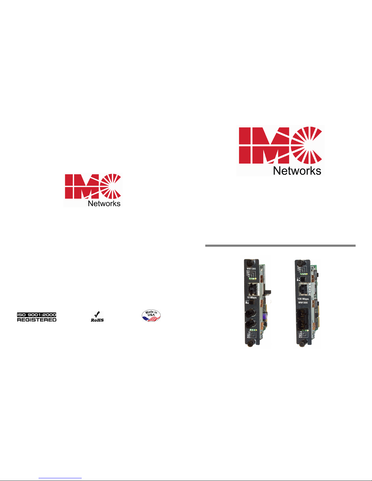
iMcV-Modules
Operation Manual
Page 2
ii
FCC Radio Frequency Interference Statement
This equipment has been tested and found to comply with th e limits for a Class B computing device, pursuant to Part 15 of the FCC Rules.
These limits are designed to provide reasonable protection against harmful interference when the equipment is operated in a commercial
environment. This equipment generates, uses and can radiate radio frequency energy and, if not installed and used in accordan ce with the
instruction manual, may caus e harmful interference to ra dio communications. Operation of this e quipment in a residential area is likely to
cause harmful interference in whic h the user will be required to correct the interference at his own expense.
Any changes or modifications not expressly approved by th e manufacturer could void the user’s authority to operate the equipmen t.
The use of non-shielded I/O cables may not guarantee complian ce with FCC RFI limits. This digital apparatus does not exceed the Class B
limits for radio noise emission from digital apparatus set out in the Radio Interference Regulation of the Canadi an Department of
Communications.
Le présent appareil numérique n’émet pas de bruits radioélectriques dépassant les limites applicables aux appareils numériques de classe B
prescrites dans le Règlement sur le brouillage radioélectrique publié par le ministère des Communications du Canada.
Warranty
IMC Networks warrants to the original end- user purchaser that this product, EXCL USIVE OF SOFTWARE, shall be free
from defects in materials and workm anship under normal and proper use in accordance with IMC Network s'
instructions and directions for a period of six (6) years after the original date of purchase. This warranty is subject to the
limitations set forth below.
At its option, IMC Networks will repair or replace at no charge the product which proves to be defective within such
warranty period. This limited warranty shal l not apply if the IMC Networks product has been d amaged by
unreasonable use, accident, negligence, service or modification by anyone other than an authorized IMC Networks
Service Technician or by any other causes unrelated to defective materials or workmanship. Any replaced or repaired
products or parts carry a ninety (90) day warranty or the remainder of the initial warranty period, whichever is longer.
To receive in-warranty service, the defective product must be received at IMC Networks no later than the end of the
warranty period. The product must be accompanied by proof of purchase, satisfactory to IMC Networks, denoting
product serial number and purchase date , a written description of the defect and a Return Merchandise Authorization
(RMA) number issued by IMC Networks. No products will be accepted by IMC Networks which do not have an RMA
number. For an RMA number, contact IMC Networks at PHONE: (800) 624-1070 (in the U.S. and Canada) or (949)
465-3000 or FAX: (949) 465-3020. The end-user shall ret urn the defective product to IMC Networks, freight, customs
and handling charges prepaid. End-user agrees to accept all liability for loss of or damages to the returned product
during shipment. IMC Networks shall repair or replace the retur ned product, at its option, and return the repaired or
new product to the end-user, freight prepaid, via method to be determined by IMC Networks. IMC Net works shall not
be liable for any costs of procurement of substitute good s, loss of profits, or any incidental, consequential, and/or
special damages of any kind resulting from a breach of any applicable express or implied warranty, breach of any
obligation arising from breach of warranty, or otherwise with respect to the manufacture and sale of any IMC Networks
product, whether or not IMC Networks has been advised of the possibility of such loss or damage.
EXCEPT FOR THE EXPRESS WARRANTY SET FORTH AB OVE, IMC NETWORKS MAKES NO OTHER WARRANTIES,
WHETHER EXPRESS OR IMPLIED, WITH RESPECT TO THIS IMC NETWORKS PRODUCT, INCLUDING WITHOUT
LIMITATION ANY SOFTW ARE ASSOCIATED OR IN CLUDED. IMC NETWORKS SHALL DISREGARD AND NOT BE
BOUND BY ANY REPRESENTATIONS OR WARRANTIES MADE BY ANY OTHER PERSON, INCLUDING EMPLOYEES,
DISTRIBUTORS, RESELLERS OR DEALERS OF IMC NETWORKS, WHICH ARE INCONSISTENT WITH THE
WARRANTY SET FORTH ABOVE. ALL IMPLIED WARRANTIES INCLUDING THOSE OF MERCHANTABILITY AND
FITNESS FOR A PARTICULAR PURPOSE ARE H EREBY LIMITED TO THE DURATION OF THE EXPRESS WARRANTY
STATED ABOVE.
Every reasonable effort has been made to ensure that IMC Networks product manuals and promotional materials
accurately describe IMC Networks product specifications an d capabilities at the time of publication. However, because
of ongoing improvements and updating of IMC Networks products, IMC Networks cannot guarantee the accuracy of
printed materials after the date of publication and disc laims liability for changes, erro rs or omissions.
11
Safety Certifications
UL/CUL: Listed to Safety of Information Technology Equipment, including
Electrical Business Equipment.
CE: The products described herein comply with the Council Directive
on Electromagnetic Compatibility (89/336/EEC) and the Council
Directive on Electrical Equipment Designed for use within Certain
Voltage Limits (73/23/EEC). Certified to Safety of Information
Technology Equipment, Including Electrical Business Equipment.
For further details, contact IMC Networks.
European Directive 2002/96/EC (WEEE) requires that any equipment that bears
this symbol on product or packaging must not be disposed of with unsorted
municipal waste. This symbol indicates that the equipment should be disposed of
separately from regular household waste. It is the consumer’s responsibility to
dispose of this and all equipment so marked through designated collection
facilities appointed by government or local authorities. Following these steps
through proper disposal and recycling will help prevent potential negative
consequences to the environment and human health. For more detailed
information about proper disposal, please contact local authorities, waste disposal
services, or the point of purchase for this equipment.
Class 1 Laser product, Luokan 1 Laserlaite,
Laser Klasse 1
, App
areil A’Laser de Classe 1
Page 3

10
General Information
IMC Networks Technical Support
Tel:
(949) 465-3000 or (800) 624-1070 (in the U.S. and Canada);
+32-16-550880 (Europe)
Fax:
(949) 465-3020
E-Mail:
Web:
www.imcnetworks.com
Specifications
Power Consumption (Typical @ 5 V):
iMcV-PIM: 0.30 Amp.
iMcV-LIM: 0.80 Amp.
iMcV-S2MM/M2MM/S2SM: 0.62 Amp.
Operating Temperature:
32° to 122° F (0° to 50° C)
Storage Temperature:
0° to 160°F (-20° to 70° C)
Humidity:
5 to 95% (non-condensing); 0 to 10,000 ft. altitude
Dimensions:
Single Slot iMcV module
iii
Table of Contents
FCC Radio Frequency Interference Statement ....................................................ii
Warranty............................................................................................................ii
About the iMcV-Modules .................................................................................. 1
Configuration Instructions.................................................................................. 2
Installation ........................................................................................................ 7
LED Operation.................................................................................................. 8
Installation Troubleshooting............................................................................... 9
General Information........................................................................................ 10
Safety Certifications......................................................................................... 11
Page 4

iv
Notes
9
Installation Troubleshooting
• During installation, first test the fiber and twisted pair connections with all
troubleshooting features disabled, then enable these features, if desired, just
before final installation. This will reduce the features’ interference with
testing.
•
When working with units where the features cannot be disabled, you must
establish BOTH your twisted pair and fiber connections before the link LEDs
will light!
•
To test a media converter by itself, first make sure you have an appropriate
fiber patch cable, then follow these steps to test:
1.
1: Connect the media converter to the twisted pair device with a twisted
pair cable.
2.
Loop a single strand of fiber from the transmit port to the receive port of
your media converter.
3.
Verify that you have both twisted pair and fiber link (see LEDs, below) on
your media converter.
•
Make sure to use the appropriate twisted pair cable, and have the
crossover/pass-through switch set correctly.
•
Whenever possible, set the devices connected to the media converter (hub,
switch, NIC card) to the desired speed and Duplex setting, and turn AutoNegotiation OFF. (See page 7 for information on Auto-Negotiation.) Also
make sure to configure the devices on the opposite sides of the media
converter to operate at the same speed and Duplex setting.
NOTE
Some 10/100 devices can't be set by the end user, and must auto-negotiate to
receive a signal.
Page 5
8
LED Operation
Each iMcV Module features diagnostic LEDs that provide information on features
and ports.
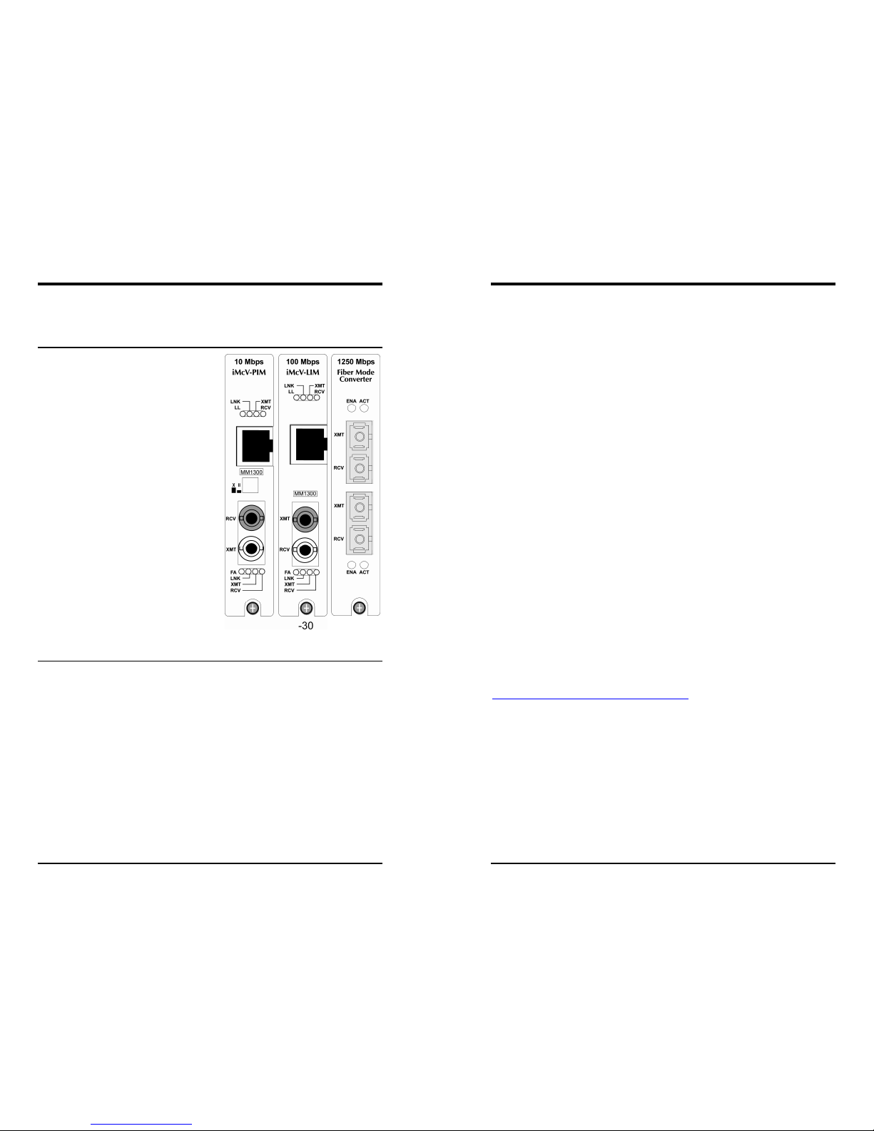
LEDs on iMcV-LIM and iMcV-PIM
The LEDs and their locations are the
same on iMcV-LIM and iMcV-PIM
Modules. The LED functions are as
follows:
•
LL - Glows green when FX LinkLoss
is enabled.
•
LNK
- Glows green when a link is
established on the port.
•
XMT
- Blinks green when port is
transmitting data.
•
RCV
- Blinks yellow when port is
receiving data.
•
FA* - Glows green when FiberAlert is
enabled.
*FiberAlert is not available/applicable on
single-strand versions of iMcV-LIM.
LEDs on iMcV-S2MM/S2SM/M2MM
The LED functions on iMcV-S2MM/S2SM/M2MM are as follows:
•
ENA
Glows green when port is enabled.
•
ACT
Glows yellow in normal operation, indicating that fiber is connected and
the receiver is seeing light pulses. (As these are protocol-independent
modules, there is no true “link” signal available.)
1
About the iMcV-Modules
iMcV Modules are SNMP-manageable and install in the modular, SNMPmanageable iMediaChassis, iMediaCenter, and in the unmanaged MediaChassis
series. The following media conversion and fiber mode conversion iMcV
Modules are described in this manual:
•
iMcV-PIM
Ethernet module providing a single conversion between 10Base-T twisted pair
and 10Base-FL single-mode or multi-mode fiber. Each iMcV-PIM includes
one RJ-45 connector and one pair of ST or SC fiber optic connectors.
•
iMcV-LIM
Fast Ethernet module provides a single conversion between 100Base-TX
twisted pair and 100Base-FX/SX single-mode or multi-mode fiber. Each iMcVLIM includes one RJ-45 connector and one pair of ST or SC fiber optic
connectors (or one small form factor connector).
Also available in a single-strand fiber version, iMcV-LIM TX/SSFX allows two
wavelengths to share one fiber strand — Full-Duplex data travels on different
wavelengths (1310 nm and 1550 nm) — doubling the capacity of fiber.
Includes one RJ-45 connector and one SC fiber connector.
•
iMcV-S2MM/M2MM/S2SM
Protocol-independent modules provide a single conversion between singlemode and multi-mode (S2MM*) fiber, 1300 nm to 1550 nm single-mode
(S2SM), or 850 nm to 1300 nm multi-mode (M2MM). Supported transmission
speeds are: 10-155 Mbps and 622- 1250 Mbps. Each module includes two
pairs of ST or SC fiber optic connectors (or small form factor connector).
Single-strand fiber versions also available.
For information about other iMcV Modules refer to their respective manuals, and
datasheets on the IMC Networks Web site at:
http://www.imcnetworks.com/tech/techsup.asp
Page 6
2
Configuration Instructions
Many iMcV Modules have user-configurable features (e.g., FiberAlert, LinkLoss,
Auto-Negotiation, etc.). Refer to the chart for information on available features
on each module. Instructions for configuring both managed (via an SNMPcompatible management application like iView²) and unmanaged modules
follow.
Managed Modules
To manage one or more iMcV Modules, an SNMP agent must be present in the
chassis: an iMediaCenter chassis has embedded management where an
iMediaChassis chassis uses an SNMP module. To configure managed modules,
install the module first, then configure it by using the management software.
Refer to the iView² for Media Converters online help for more information and
assistance.
NOTE
Management software overrides any hardware settings (e.g., jumper, switch, etc.),
so you must make sure the module is configured through the software before
beginning normal operation. Until a module installed in a managed chassis is
configured via the software, it will operate using the hardware configuration.
Unmanaged Modules
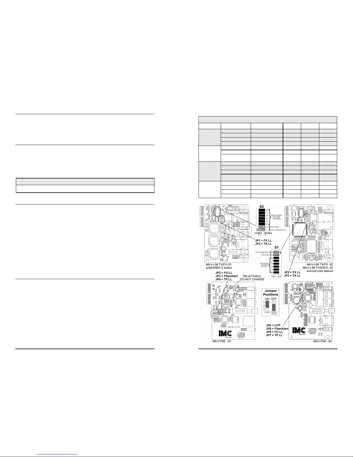
Before beginning installation of the iMcV Modules, configure them for the desired
features. The chart on page 2 states the available features and settings for the
iMcV-PIM and iMcV-LIM modules. The diagrams on the next page show the
jumper/switch locations on the modules. There are no user-configurable features
on the iMcV-S2MM/ S2SM/ M2MM modules; which can therefore be installed
straight from the box.
After configuring the jumpers/switches for the desired settings, install the module
and connect the appropriate cables (refer to the
Installation
section for more
information).
7
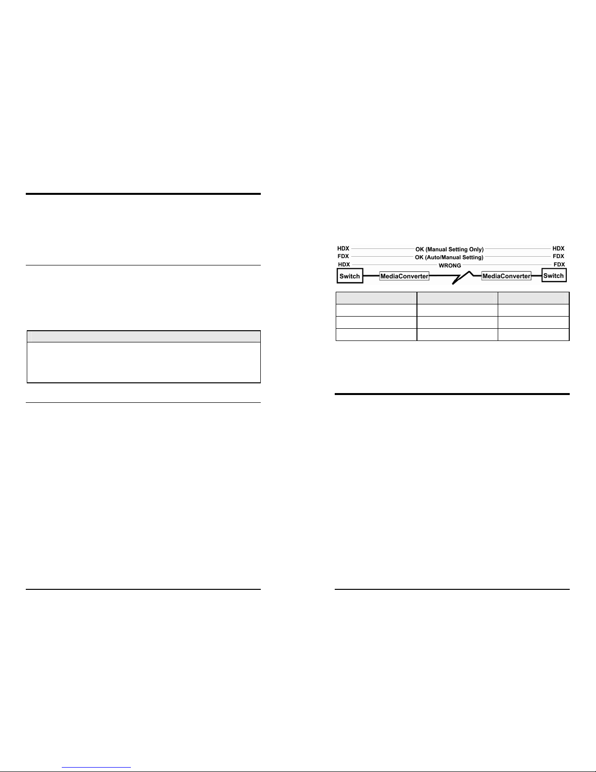
If the twisted pair port on the other device does not have the ability to autonegotiate, or if a 100 Mbps Half-Duplex connection is desired, Auto-Negotiation
on iMcV-LIM must be disabled. Half- and Full-Duplex settings must be manually
set, and match, on both devices connected to the iMcV-LIM. The follwing
diagram shows a typical application, followed by a table with three possible
configurations.
End to End Connection Switch McPC TX/FX
Half-Duplex Manually Configure HDX Auto-Negotiation OFF
Full-Duplex Manually Configure FDX Auto-Negotiation OFF
Full -Duplex Auto-Negotiation ON Auto-Negotiation ON
Configure Auto-Negotiation on an iMcV-LIM by adjusting the DIP switch setting
(for unmanaged modules) or via the management software. Refer to the diagrams
in this manual for switch location and settings.
Installation
iMcV Modules install in any IMC Networks SNMP-manageable media converter
chassis or in any MediaChassis. To install an iMcV Module, remove the blank
bracket covering the slot where the module is to be installed by removing the
screws on the outside edges of the bracket. Slide the iMcV Module into the
chassis, via the cardguides, until the module is seated securely in the connector.
Secure the module to the chassis by tightening the captive screw. Save any
“blanks” removed during installation for future use should configuration
requirements change.
Page 7
6
Configuring LinkLoss and FiberAlert
iMcV-PIM and iMcV-LIM Modules ship from the factory with troubleshooting
features disabled. See the configuration instructions in this manual for
instructions on enabling FiberAlert and LinkLoss.
Twisted Pair Cable Type
The twisted pair port on iMcV-McPIMs features a jumper, located at position JP6,
for selecting either a shielded or unshielded twisted pair link segment. The
factory default is unshielded twisted pair with the jumper shunt on pins 1-2.
Place the jumper shunt over pins 2-3 to select a shielded twisted pair link
segment.
NOTE
This jumper is not found on -20 iMcV-McPIM boards.
Twisted Pair Crossover/Straight-Through Connections
iMcV Modules support both crossover and straight-through CAT5 twisted pair
cabling types of connections by one of the following two methods:
AutoCross: iMcV-LIM Modules include AutoCross, a feature which automatically
selects between a crossover workstation or straight-through/repeater hub
connection depending on the connected device.
MDI/MDI-X Switch: iMcV-PIMs feature a push button switch, located next to the
RJ-45 connector, for selecting the type of connection. Select a straight-through
connection by pressing the push-button IN. The button should be in the OUT
position for a crossover connection. If unsure of the type of connection, set the
push button to a position that makes the twisted pair LNK (link) LED glow.
Auto-Negotiation on iMcV-LIM
iMcV-LIM Modules include the feature Auto-Negotiation. When AutoNegotiation is enabled, the module negotiates as a 100 Mbps Full-Duplex device;
if the device the iMcV-LIM is connected to can operate at 100 Mbps Full-Duplex,
a link will be established.
3
iMcV Module Jumper/Switch Configuration Chart
Module Feature Jumper/Switch ON OFF Default
UTP JP6 1-2 2-3 ON
FiberAlert JP8 1-2 2-3 OFF
FO LinkLoss JP9 1-2 2-3 OFF
iMcV-PIM
TP/FO
-40 Board
TP LinkLoss JP7 1-2 2-3 OFF
FO LinkLoss JP2 1-2 2-3 OFF
FiberAlert JP3 1-2 2-3 OFF
iMcV-PIM
TP/FO
-20 Board
TP LinkLoss JP6 1-2 2-3 OFF
FX LinkLoss JP2 1-2 2-3 OFF
TX LinkLoss JP3 1-2 2-3 OFF
Auto-Negotiation DIP Switch 1 on S1 see board see board ON
iMcV-LIM
TX/FX and
TX/SSFX
-30 Board
FiberAlert* DIP Switch 2 on S1 see board see board OFF
FX LinkLoss JP1 1-2 2-3 OFF
TX LinkLoss JP2 1-2 2-3 OFF
Auto-Negotiation DIP Switch 1 on S2 see board see board ON
iMcV-LIM
TX/FX
-20 Board
FiberAlert DIP Switch 2 on S2 see board see board OFF
Page 8

4
About LinkLoss and FiberAlert
Some iMcV Modules include advanced troubleshooting features that help locate
"silent failures" on your network. Troubleshooting features include:
•
FO/FX LinkLoss (a.k.a. "Fiber LinkLoss" or "LinkLoss")
•
TP/TX LinkLoss (a.k.a. "Twisted Pair LinkLoss” or "Reverse LinkLoss”)
•
FiberAlert
It is important that you understand how FiberAlert and LinkLoss work, and how
they will react in your network configuration, before attempting to install the
enclosed module(s).
** WARNING **
Installing modules without understanding the effects of FiberAlert and LinkLoss
can cause perfectly functioning units to appear flawed or even dead.
About Link Integrity
During normal operation, link integrity pulses are transmitted by all point-to-point
Ethernet devices. When an IMC Networks media converter receives valid link
pulses, it knows that the device to which it is connected is up and sending pulses,
and that the copper or fiber cable coming from that device is intact. The
appropriate “LNK” (link) LED is lit to indicate this.
The IMC Networks media converter also sends out link pulses from its copper and
fiber transmitters, but normally has no way of knowing whether the cable to the
other device is intact and the link pulses are reaching the other end. The
combination of FiberAlert and LinkLoss allows this information to be obtained,
even when physical access to a remote device (and its link integrity LED) is not
available.
What Is FO/FX LinkLoss?
FO/FX LinkLoss is a troubleshooting feature. When a fault occurs on the fiber
segment of a conversion, FO/FX LinkLoss detects the fault and passes this
information to the twisted pair segment. If a media converter is not receiving a
fiber link, FO/FX LinkLoss disables the transmitter on the media converter's
twisted pair port. This results in a loss of link on the device connected to the
twisted pair port.
5
What Is TP/TX LinkLoss?
TP/TX LinkLoss is another troubleshooting feature. When a fault occurs on the
twisted pair segment of a conversion, TP/TX LinkLoss detects the fault and passes
this information to the fiber segment. If a media converter is not receiving a
twisted pair link, TP/TX LinkLoss disables the transmitter on the media converter's
fiber port. This results in a loss of link on the device connected to the fiber port.
What Is FiberAlert?
FiberAlert minimizes the problems associated with the loss of one strand of fiber.
If a strand is unavailable, the IMC Networks device at the receiver end notes the
loss of link. The device will then stop transmitting data and the link signal until a
signal or link pulse is received. The result is that the link LED on BOTH sides of
the fiber connection will go out indicating a fault somewhere in the fiber loop.
Using FiberAlert, a local site administrator is notified of a fault and can quickly
determine where a cable fault is located.
NOTE
Enable FiberAlert only on one side of the media conversion; enabling it on both
sides will keep both transmitters off indefinitely!
Using FiberAlert and LinkLoss
The following chart provides an overview of the troubleshooting features, their
functionality and the recommended settings for a pair of media converters in a
typical central/main site to remote site application:
FiberAlert and LinkLoss
Feature Enabled Fault Location Disabled LEDs
FiberAlert
Remote Site Only Fiber Fiber
TX LinkLoss
Remote Site Only Twisted Pair Fiber
FX LinkLoss
Home Site (or both) Fiber Twisted Pair
his will ensure that any faults, no matter where they occur, can be detected by an
administrator located at the central site.
For more information on LinkLoss and FiberAlert, please visit the IMC Networks
Web site at:
http://www.imcnetworks.com/tech/ref-features.asp
If you are unsure of how best to implement these features in your configuration,
please contact IMC Networks technical support at (800) 624-1070 (U.S./Canada),
+32-16-550880 (Europe) or via e-mail at:
 Loading...