

IMC Networks iMcV-Giga-FiberLinX-II User Manual
iMcV-Giga-FiberLinX-II
Operation Manual

FCC Radio Frequency Interference Statement
This equipment has been tested and found to comply with the limits for a Class B computing device, pursuant to Part 15 of the FCC Rules.
These limits are designed to provide reasonable protection against harmful interference when the equipment is operated in a commercial
environment. This equipment generates uses and can radiate radio frequency energy and, if not installed and used in accordance with the
instruction manual, may cause harmful interference to radio communications. Operation of this equipment in a residential area is likely to
cause harmful interference in which the user will be required to correct the interference at his own expense.
Any changes or modifications not expressly approved by the manufacturer could void the user’s authority to operate the equipment.
This digital apparatus does not exceed the Class B limits for radio noise emission from digital apparatus set out in the Radio Interference
Regulation of the Canadian Department of Communications.
Le présent appareil numérique n’émet pas de bruits radioélectriques dépassant les limites applicables aux appareils numériques de classe B
prescrites dans le Règlement sur le brouillage radioélectrique publié par le ministère des Communications du Canada.
Warranty
IMC Networks warrants to the original end-user purchaser that this product, EXCLUSIVE OF SOFTWARE, shall be free
from defects in materials and workmanship under normal and proper use in accordance with IMC Networks' instructions
and directions for a period of six (6) years after the original date of purchase. IMC Networks warrants to the original enduser purchaser that all SFPs shall be free from defects in materials and workmanship under normal and proper use in
accordance with IMC Networks' instructions and directions for a period of one (1) year after the original date of purchase.
This warranty is subject to the limitations set forth below.
At its option, IMC Networks will repair or replace at no charge the product which proves to be defective within such
warranty period. This limited warranty shall not apply if the IMC Networks product has been damaged by unreasonable
use, accident, negligence, service or modification by anyone other than an authorized IMC Networks Service Technician
or by any other causes unrelated to defective materials or workmanship. Any replaced or repaired products or parts carry
a ninety (90) day warranty or the remainder of the initial warranty period, whichever is longer.
To receive in-warranty service, the defective product must be received at IMC Networks no later than the end of the
warranty period. The product must be accompanied by proof of purchase, satisfactory to IMC Networks, denoting
product serial number and purchase date, a written description of the defect and a Return Merchandise Authorization
(RMA) number issued by IMC Networks. No products will be accepted by IMC Networks which do not have an RMA
number. For an RMA number, contact IMC Networks at PHONE: (800) 624-1070 (in the U.S and Canada) or (949) 4653000 or FAX: (949) 465-3020. The end-user shall return the defective product to IMC Networks, freight, customs and
handling charges prepaid. End-user agrees to accept all liability for loss of or damages to the returned product during
shipment. IMC Networks shall repair or replace the returned product, at its option, and return the repaired or new
product to the end-user, freight prepaid, via method to be determined by IMC Networks. IMC Networks shall not be
liable for any costs of procurement of substitute goods, loss of profits, or any incidental, consequential, and/or special
damages of any kind resulting from a breach of any applicable express or implied warranty, breach of any obligation
arising from breach of warranty, or otherwise with respect to the manufacture and sale of any IMC Networks product,
whether or not IMC Networks has been advised of the possibility of such loss or damage.
EXCEPT FOR THE EXPRESS WARRANTY SET FORTH ABOVE, IMC NETWORKS MAKES NO OTHER WARRANTIES,
WHETHER EXPRESS OR IMPLIED, WITH RESPECT TO THIS IMC NETWORKS PRODUCT, INCLUDING WITHOUT
LIMITATION ANY SOFTWARE ASSOCIATED OR INCLUDED. IMC NETWORKS SHALL DISREGARD AND NOT BE
BOUND BY ANY REPRESENTATIONS OR WARRANTIES MADE BY ANY OTHER PERSON, INCLUDING EMPLOYEES,
DISTRIBUTORS, RESELLERS OR DEALERS OF IMC NETWORKS, WHICH ARE
INCONSISTENT WITH THE WARRANTY SET FORTH ABOVE. ALL IMPLIED WARRANTIES INCLUDING THOSE OF
MERCHANTABILITY AND FITNESS FOR A PARTICULAR PURPOSE ARE HEREBY LIMITED TO THE DURATION OF THE
EXPRESS WARRANTY STATED ABOVE.
Every reasonable effort has been made to ensure that IMC Networks product manuals and promotional materials
accurately describe IMC Networks product specifications and capabilities at the time of publication. However, because of
ongoing improvements and updating of IMC Networks products, IMC Networks cannot guarantee the accuracy of printed
materials after the date of publication and disclaims liability for changes, errors or omissions.
ii

Table of Contents
FCC Radio Frequency Interference Statement ------------------------------------------------ ii
Warranty---------------------------------------------------------------------------------------------- ii
I - About the iMcV-Giga-FiberLinX-II ------------------------------------------------------------1
Overview ------------------------------------------------------------------------------------------1
Serial Craft Port Connection -------------------------------------------------------------------2
iView Management Software2-----------------------------------------------------------------3
iConfig Utility -------------------------------------------------------------------------------------3
About Dynamic Host Control Protocol (DHCP) -------------------------------------------4
II - LED Operation ----------------------------------------------------------------------------------5
III - Hardware Configuration ----------------------------------------------------------------------6
DIP Switch Settings------------------------------------------------------------------------------6
Host/Remote and Standalone Units----------------------------------------------------------6
Management--------------------------------------------------------------------------------------7
IV - Installation Instructions -----------------------------------------------------------------------8
Small Form-Factor Pluggable Ports (SFP) ----------------------------------------------------8
V - Software Configuration ------------------------------------------------------------------------8
Assigning IP Information ------------------------------------------------------------------------9
Autonegotiation, Duplex Mode, and Speed------------------------------------------------9
FX/TX LinkLoss and FiberAlert--------------------------------------------------------------- 10
Link Fault Pass-Through ---------------------------------------------------------------------- 11
Loopback Testing on Remote or Standalone --------------------------------------------- 12
VI - Using Telnet ---------------------------------------------------------------------------------- 13
Serial Configuration/Telnet Session--------------------------------------------------------- 13
Basic Device Configuration ------------------------------------------------------------------ 14
(Space Bar)—Commands List---------------------------------------------------------------- 17
Clean Database—cleandb ---------------------------------------------------------------- 18
Downloading Files—download ---------------------------------------------------------- 18
Port Configuration—port------------------------------------------------------------------ 19
Mode Configuration—config ------------------------------------------------------------- 20
Transparent Mode ----------------------------------------------------------------------------- 21
VLAN Mode Screen --------------------------------------------------------------------------- 23
Unit Configuration—unit --------------------------------------------------------------------- 25
Bandwidth Configuration—bw-------------------------------------------------------------- 27
VII - Application Overview ---------------------------------------------------------------------- 28
How many iMcV-Giga-FiberLinX-II units will you use?--------------------------------- 28
How do you want to manage iMcV-Giga-FiberLinX-II? -------------------------------- 28
Will you define VLAN IDs? ------------------------------------------------------------------ 29
VIII - Application Examples---------------------------------------------------------------------- 29
Default ------------------------------------------------------------------------------------------- 29
Transparent with Untagged Management------------------------------------------------- 30
Transparent with Tagged Management---------------------------------------------------- 32
iii

Transparent with Extra Tagging (Q-in-Q) -------------------------------------------------- 34
Port VLAN--------------------------------------------------------------------------------------- 36
Port VLAN Filter-------------------------------------------------------------------------------- 40
IX - Troubleshooting ------------------------------------------------------------------------------ 43
Troubleshooting LinkLoss/FiberAlert/Link Fault Pass-Through------------------------- 45
IMC Networks Technical Support-------------------------------------------------------------- 50
Specifications -------------------------------------------------------------------------------------- 50
Standards/Compliance --------------------------------------------------------------------------- 50
Serial Port Pinout---------------------------------------------------------------------------------- 51
Safety Certifications------------------------------------------------------------------------------- 55
iv

I - About the iMcV-Giga-FiberLinX-II
Overview
The iMcV-Giga-FiberLinX-II™ allows network operators to deploy managed Ethernet
services, with a full range of remote management, traffic monitoring, and alarm
reporting features. This unit converts 1000 Mbps fiber to 10/100/1000 Mbps copper.
In addition, a range of fiber connectors (SC, ST, or SFP) and a variety of wavelengths,
supporting higher density CWDM and single-strand fiber operation are available.
The iMcV-Giga-FiberLinX-II supports two main configuration modes: Standalone or
Host/Remote. When using Host/Remote, the Remote modules can be fully managed
without an IP address using a secure management channel (when the SNMP module
is installed in the same chassis). In either mode, the network operator can choose to
assign an IP address to the Host or Standalone module. Or, if using a local
iMediaChassis managed chassis, all local and remotely connected iMcV-GigaFiberLinX-II modules can be managed using the single IP address of the chassis. This
not only preserves IP addresses and reduces configuration complexity, but
management traffic traveling on the non-IP based transmission channel is kept
isolated from customer traffic, enhancing network security.
The iMcV-Giga-FiberLinX-II offers the following features:
• Securely separates the SNMP management network from the data network
•
IEEE 802.1Q VLAN Tagging
•
Q-in-Q VLAN Extra-Tagging
•
Remote traffic monitoring
•
Remote automatic alarms
•
Bandwidth limiting
•
FiberAlert (loss return)
•
FX and TX LinkLoss (loss pass-through)
•
Loopback testing
•
Autonegotiation
•
Selective Advertising
•
AutoCross
1

The iMcV-Giga-FiberLinX-II module is a double-slot, chassis-mounted module.
Compatible chassis include the following:
• iMediaChassis series
• MediaChassis series
Port Interfaces
Every iMcV-Giga-FiberLinX-II includes the following port:
• A 10/100/1000 twisted pair port (EXT MGMT) for management
One of the following uplink ports:
• One fixed 1000 Mbps Fiber port
• A SFP port capable of receiving a gigabit fiber optic SFP module or a
gigabit twisted pair (RJ-45) SFP module
And one of the following DATA ports:
• A 10/100/1000 twisted pair (RJ-45) port
• A SFP port capable of receiving a gigabit fiber optic SFP module or a gigabit
twisted pair (RJ-45) SFP module
In addition, a DB-9 port is available for management through a serial port
connection. Refer to Serial Port Pinout on page 51
for more information.
You can easily configure the iMcV-Giga-FiberLinX-II by using either the serial craft
port connection, through SNMP management application such as iView² or a Telnet
session.
Serial Craft Port Connection
The RS-232 serial connection through the DB-9 connector on the module provides
access to the iMcV-Giga-FiberLinX-II module configuration screens. The
configuration screens are also accessible from a Telnet connection.
2

2
iView Management Software
iView² is the IMC Networks management software designed specifically for the IMC
Networks “iMcV” family of modules. It features a graphical user interface (GUI) and
gives network managers the ability to monitor and control the manageable IMC
Networks products.
2
iView
is available in several versions and can also function as a snap-in module for
HP OpenView
TM
Network Node Manager. For assistance in selecting the right version
of iView² for your operating system, please visit:
http://www.imcnetworks.com/products/iview2.cfm
2
iView supports the following platforms:
Windows™ 98 • Windows NT • Windows 2000 • Windows XP • Windows Vista
In addition, there are Java versions of iView² for other Java capable operating systems
such as Linux.
iConfig Utility
iConfig is a configuration utility in iView² that lets you quickly and easily complete the
initial SNMP configuration for IMC Networks’ SNMP-manageable devices. With
iConfig you can set the IP address, set the Subnet Mask and Default Gateway, define
the Community Strings, and define SNMP Traps. iConfig can also be used to upload
new versions of unit software.
iConfig offers an authorized IP address system and access restriction to MIB groups
supported by the IMC Networks manageable devices. These extra layers of security
are purely optional and do not effect SNMP compatibility in any way.
Default Username/Password
The default user ID and password for both iConfig and Telnet are the following:
• User–
• Password–
admin
admin
Refer to (P) - Password Protection/Changing Passwords on page 15 for information
about setting or changing passwords.
NOTE
It is the responsibility of the network administrator to store and maintain the
password lists.
3

About Dynamic Host Control Protocol (DHCP)
The iMcV-Giga-FiberLinX-II module includes a Dynamic Host Control Protocol
(DHCP) client. By default, the DHCP client is disabled. When a DHCP server is
enabled on the network, the DHCP client will initiate a dialogue with the server
during the boot up sequence. The server will then issue an IP address, Default
Gateway address and Subnet mask to the module. After the new IP address is
received, the iMcV-Giga-FiberLinX-II will reboot with the new IP address.
When a DHCP server is not on the network, ensure that DHCP is disabled an
iConfig or serial configuration to manually set the IP addresses (refer to the
Configuration/Telnet Session
section for DHCP Enable/Disable information).
If an IP address is already assigned to the device, and DHCP is then enabled,
d use
Serial
that
original IP address is saved. When DHCP is disabled, the saved IP address will be
reinstated and the device will reboot.
4
A
r
II - LED Operation
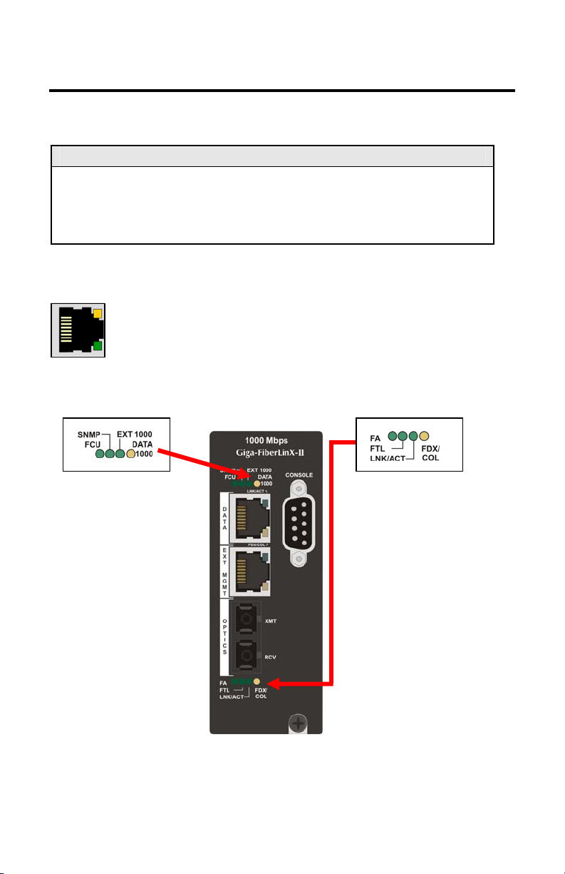
The following are iMcV-Giga-FiberLinX-II diagnostic LEDs. In this example, the
functions for a 1x9 fiber port version (SC fiber) are shown below.
NOTE
In the SFP/SFP version the LNK/ACT and FDX/COL LEDs replace EXT 1000 and
DATA 1000 for the top SFP, which does not have built-in LEDs like the RJ-45
DATA port. In addition, the copper SFP LNK/ACT LED glows green (does not
flicker).
Port LEDs
FDX/COL
:
• Glows yellow when port is operating in Full-Duplex.
• Blinks yellow when collisions occur on port.
LNK/ACT
:
• Glows green when link is established on port.
• Blinks green during data activity on port.
Diagnostic LEDs Optics Port LEDs
Optics Port LEDs
FA:
FCU (Far CPU Up):
•
Host:
far end is detected.
Remote:
•
for Remote units.
Standalone
•
remains OFF.
SNMP:
Glows green with SNMP
activity.
EXT 1000:
Glows green when EXT
MGMT
port is operating at 1000
Mbps.
DATA 1000:
Glows yellow when D
is operating at 1000 Mbps.
Glows green when
Glows green
: LED
TA po
5
Glows green when FiberAlert is enabled.
FTL (Far TX Link):
• Host
established on remote (far-end) DATA
port.
Remote
•
configured as Remote.
Standalone
•
LNK/ACT (Link/Activity):
• Glows green when link is established on
port.
Blinks green during data activity on port.
•
FDX/COL (Full Duplex/Collision):
• Glows yellow when port is operating in
Full-Duplex.
Blinks yellow when collisions occur on
•
port.
: Glows green when a link is
: Glows green when unit is
: LED remains OFF.

III - Hardware Configuration
Before installing the module in a chassis, there are two features that must be selected
using the DIP switches. These selections are:
•
Enable or disable management on each port
(DIP switches 1, 2, and 3)
•
Configure the module as a standalone, a host, or a remote
(DIP switches 7 and 8)
DIP Switch Settings
Before installing the iMcV-Giga-FiberLinX-II, use the DIP switches to set the
hardware-configurable features. The DIP switches are located on switch SW1 on the
iMcV-Giga-FiberLinX-II card. Refer to the diagram and table for switch settings and
available features.
Switch Function Default Setting
1
2
3
4
5
6
7
8
9
0
Management on EXT MGMT port ON
Management on DATA port
Management on OPTICS or
UPLINK port
Factory use - Do not change
Factory use - Do not change
Factory use - Do not change
Remote Module OFF
Host Module OFF
Factory use - Do not change
Factory use - Do not change
---
OFF
OFF
---
---
---
---
Host/Remote and Standalone Units
The iMcV-Giga-FiberLinX-II can be used as a Host, Remote, or Standalone unit.
Refer to the
When two iMcV-Giga-FiberLinX-II units are used as a pair, configure one as a Host
unit (DIP switch 8 = ON) and the other as a Remote unit (DIP switch 7 = ON). As a
host unit, the iMcV-Giga-FiberLinX-II requests management information from the
attached remote unit. It then displays that information, along with its own, when
Application Examples
section for examples.
6

queried by SNMP. As a Remote unit, the iMcV-Giga-FiberLinX-II will respond to
requests for management information from an attached Host unit.
The iMcV-Giga-FiberLinX-II default configuration is as a Standalone unit (DIP switches
7 and 8 = OFF).
Management
Although the iMcV-Giga-FiberLinX-II provides a twisted pair port solely for
management (EXT MGMT), you can configure iMcV-Giga-FiberLinX-II to accept IPbased management traffic from any of its three ports. You can enable management
on more than one port, or you can disable management on all of the ports, if desired.
These switches limit only IP-based management. Host-to- Remote management is IPless and is never blocked from the fiber port. Serial port management of the Host
unit is always available on the DB-9 port regardless of the DIP switch settings.
In addition to defining which ports are used to manage the iMcV-Giga-FiberLinX-II
units, the management DIP switch settings also define what ports the flow of the
network provider’s Management Domain traffic can take through the unit. By
configuring a unique Management Domain, a Host/Remote pair of units can extend a
secure-management LAN to a remote location to manage other equipment at the
remote site.
7

g
IV - Installation Instructions
Each iMcV-Giga-FiberLinX-II module requires two slots in an iMediaChassis or
MediaChassis. To install the module in a chassis, remove the blank faceplates
covering the slots where you want to install the module. Then slide the module into
the chassis card guides until the module is seated securely in the connector. Secure
the module to the chassis by tightening the captive screw.
The iMcV-Giga-FiberLinX-II module includes on-board SNMP logic. A chassis other
than an iMediaChassis series cannot manage an iMcV-Giga-FiberLinX-II, so the iMcVGiga-FiberLinX-II must be managed independently.
When installed in an iMediaChassis, you can manage the iMcV-Giga-FiberLinX-II
module from the chassis by using the Unified Management Agent (UMA).
Refer to http://www.imcnetworks.com/Products/Unified_Management_Agent.cfm
for
more information about using UMA with iConfig, iMediaChassis and iMcV-GigaFiberLinX-II.
iMcV-Giga-FiberLinX-II modules not managed by UMA must have an IP address
assigned to them after installation before they can be managed. Refer to (I) Assigning IP Information on page 15
for more information.
Small Form-Factor Pluggable Ports (SFP)
iMcV-Giga-FiberLinX-II modules are available with one or two optional SFP port(s).
You must use a 1000 Mbps speed SFP for fiber connections or any gigabit copper SFP
(1000 Mbps or 10/100/100 Mbps). In addition, many SFPs, including those from
IMC Networks, feature enhanced diagnostics capabilities with a Digital Diagnostics
Monitoring Interface (DDMI). DDMI statistics provide real-time access to transceiver
operating parameters such as voltage, temperature, laser bias current, and both
transmitted and received optical power. DDMI information can be accessed in
2
iView
by clicking
Tables
>
SFP Info
.
NOTE
iMcV-Giga-FiberLinX-II has been tested with the IMC Networks SFP modules. You
can install any MSA-compliant SFP module. However, IMC Networks does not
uarantee the functionality of non-IMC Networks SFP modules due to possible non-
conformity with MSA design standards.
V - Software Configuration
The following sections describe the features you can configure. Refer to the iView²
online help for iMcV-Giga-FiberLinX-II module configuration information.
8

Assigning IP Information
When the iMcV-Giga-FiberLinX-II is installed in an iMediaChassis, you can use UMA
to manage your iMcV-Giga-FiberLinX-II without an IP address (refer to the iView²
online help for more information on UMA). When the iMcV-Giga-FiberLinX-II is not
installed in an iMediaChassis, SNMP-management is not accessible until the iMcVGiga-FiberLinX-II IP information (e.g., IP address, subnet mask, etc.) is configured
(using iConfig, a serial port DB-9 connection, or DHCP). After assigning iMcV-GigaFiberLinX-II an IP address, you can use iView² or another SNMP-compatible Network
Management System (NMS) to remotely configure, monitor and manage the iMcVGiga-FiberLinX-II.
Autonegotiation, Duplex Mode, and Speed
The DATA port (non-SFP version) and EXT MGMT port on the iMcV-Giga-FiberLinX-II
module autonegotiate for speed and duplex mode. This module also provides the
option of selectively advertising or forcing the speed and duplex mode. Refer to Port
Configuration on page 19
for more information.
AutoCross Feature for Twisted Pair Connection
All twisted pair ports on the iMcV-Giga-FiberLinX-II include AutoCross, a feature that
automatically selects between a crossover workstation and a straight-through
connection depending on the connected device. Refer to Port Configuration on page
19
for more information.
Autonegotiation
The iMcV-Giga-FiberLinX-II ships from the factory with autonegotiation enabled on
the twisted-pair and fiber ports. In this mode, the ports negotiate for speed and
duplex. Refer to Port Configuration on page 19
for more information.
Forcing the Speed and Duplex Mode
You can manually set the twisted-pair ports on the iMcV-Giga-FiberLinX-II for 10
Mbps or 100 Mbps operation at Half- or Full-Duplex (i.e., 10 Mbps FDX, 10 Mbps
HDX, 100 Mbps FDX, etc.). The OPTICS port operates at 1000 FDX. The FX port
options are either FX AN or FX Force Mode. Refer to Port Configuration on page 19
for more information.
Selective Advertising
Selective Advertising, when used in combination with autonegotiation, advertises only
the configured speed and duplex mode for the twisted pair port. If a specific speed
and/or duplex mode are desired, IMC Networks recommends using Selective
9

Advertising, rather than Force Mode, when connecting to devices that only use
autonegotiation. Refer to Port Configuration on page 19
for more information.
Bandwidth Control
Link Speed
(Mbps)
10 4.88
100 48.8
1000 244
Speed Increments
(Kbps)
The iMcV-Giga-FiberLinX-II includes bidirectional bandwidth control in increments of
244 Kbps per second at gigabit speed
(configurable via iView
2
). This allows you to
independently set the bandwidth limit from the
DATA Port to the OPTICS (or UPLINK) Port and vice versa in a single iMcV-GigaFiberLinX-II application. In a dual iMcV-Giga-FiberLinX-II application you can set it
from the Host unit to the Remote unit and vice versa (i.e., the bandwidth on the
DATA ports on both the Host and Remote modules can be limited independently).
Note
Management packets do not have priority over data packets.
FX/TX LinkLoss and FiberAlert
During normal operation, link integrity pulses are transmitted by all point-to-point
Ethernet devices. When an iMcV-Giga-FiberLinX-II receives valid link pulses, it
knows the device to which it is connected is up, and the copper or fiber cable
coming from that device is intact. The appropriate “LNK” (link) LED is lit to indicate
this. For troubleshooting information using the LinkLoss and FiberAlert features of the
iMcV-Giga-FiberLinX-II modules, refer to
** WARNING **
Troubleshooting
at the end of this manual.
The FiberAlert and LinkLoss features cause data interruptions designed to
alert remote sites of line failures. These data interruptions can be
misinterpreted as module failures when these features are enabled. Enable
these features only when the resulting data interruptions and causes are well
understood.
FX LinkLoss
FX LinkLoss is a link integrity monitoring feature that forwards fiber link faults to the
RJ-45 DATA port to indicate that a fiber link fault has occurred.
TX LinkLoss
TX LinkLoss is a link integrity monitoring feature that forwards an RJ-45 link fault to
the fiber connected device to indicate that a link fault has occurred.
10

FiberAlert
FiberAlert minimizes the problems associated with the loss of one strand of fiber.
Normally when a single strand of fiber is lost, the transmitting side of the connection
is unaware that there is a fault. FiberAlert returns faults back on the fiber they came
in on.
Using LinkLoss and FiberAlert
In a typical central site to remote site media conversion, it is recommended that you
enable the LinkLoss and FiberAlert features as indicated in the following:
FiberAlert and LinkLoss
Feature Enabled Fault Location Port affected
FiberAlert
TX LinkLoss
FX LinkLoss
Remote Side Only Fiber Fiber
Remote Side (or both) Twisted Pair Fiber
Host Side (or both) Fiber Twisted Pair
** WARNING **
Do not enable FiberAlert on both modules when using iMcV-Giga-FiberLinX-II
in pairs. This will cause them to lock up when a fault occurs on the fiber.
Only enable FiberAlert on the remote module
.
Link Fault Pass-Through
Link Fault Pass-Through (LFPT) is a troubleshooting feature that combines TX and FX
LinkLoss from both the local and remote iMcV-Giga-FiberLinX-II modules. LFPT is
enabled by turning on both FX and TX LinkLoss on both modules. This feature allows
either end of the conversion to detect a link fault occurring at the other end of the
media conversion chain:
• A cable fault occurs on the remote twisted pair.
• TX LinkLoss detects the fault and disables the OPTICS (or UPLINK) port.
• FX LinkLoss detects the fiber loss and disables the DATA port.
The link fault is passed through the media conversion and is observed at each end. It
acts just like it would if the devices were directly connected.
NOTE
FiberAlert can also be added to the remote side of the pair to further assist in
locating a fault.
11

Loopback Testing on Remote or Standalone
The following functions are available during loopback testing. During loopback
testing, management traffic entering the uplink port is still capable of managing the
device.
Address Swap
A Layer 2 Ethernet switch will discard all received packets with the same MAC
address as sent packets. To avoid this issue the Loopback feature can swap the
source and destination MAC addresses on the looped data.
Address Swap and Clear Multicast Bit
In addition to swapping the source and destination MAC addresses on the looped
data, the Loopback feature can also be set to clear the multicast bit. This allows the
looped data to avoid being blocked by any multicast settings.
No Learning on OPTICS and DATA Ports
The Loopback feature can be set to disable address learning on the OPTICS (or
UPLINK) and DATA ports, allowing the loopback to be performed without
interference from MAC address filtering functions. This is a function on the HOST
unit. Set the REMOTE unit for Loopback then set the HOST to disable learning so
Loopback frames pass from the OPTICS port to the DATA port.
12

VI - Using Telnet
You must assign the iMcV-Giga-FiberLinX-II an IP address before using a Telnet
session (this is not necessary when you are using UMA). Refer to the
Information
section for more information. All of the configurations that you can
Assigning IP
perform from the serial port can also be performed using a Telnet session. You can
only use one Telnet session at a time.
The three levels for Telnet account access are:
• User
• Operator
–view status, change own password, and reboot.
–all User privileges mentioned above, plus ability to change
settings.
• Administrator
–operator privileges mentioned above, plus ability to
add/delete accounts and reinitialize the unit to default settings (cleandb).
Serial Configuration/Telnet Session
The following sections describe serial configuration (including VLAN configuration),
Telnet session configuration, and DHCP configuration.
NOTE
Some screens may show TX and FX for the port titles where TX = DATA port and
FX = OPTICS (or UPLINK) port.
Serial Port (EXT MGMT)
NOTE
The serial port is always set to Administrator level. Your password for Telnet
sessions is the password that you set and use in iConfig. Refer to iConfig on page
3
for more information.
13

Basic Device Configuration
After running through an initial self test, the prompt: “Press <Enter> for Device
Configuration” displays. Press
Saved Values. <These values will be active after reboot>
IP Address - 10.10.10.10
Default Gateway - 000.000.000.000
New PROM File - filename
Subnet Mask - 255.0.0.0
Default Gateway - 000.000.000.000
New PROM File - filename
mmunity String: public Access: r/w Co
Press I to enter new saved parameter values. Press P to change Password.
Press T to enter new Trap Destination. Press K to remove ALL Trap Destinations.
Press SpaceBar for additional commands.
000.000.000.000 Server IP Addr -
000.000.000.000 Server IP Addr -
Enter
to open the Main Configuration screen:
DHCP is not active Subnet Mask - 255.0.0.0
n use now> Current Values. <These values are i
10 IP Address - 10.10.10.
boot unit. Press D for DHCP On/Off. Press E to End session. Type REBOOT to re
s. Press C to enter new Community String. Press U to remove ALL Community String
This screen contains the following information and options:
Saved and Current Values
Saved values display the changes made during the current session and current values
display the values currently in use:
• IP Address (IP address of SNMP agent)
• Subnet Mask (mask to define IP subnet to which agent is connected)
• Default Gateway (default router for IP traffic outside of the subnet)
• Server IP Address (TFTP server)
• New PROM File (TFTP new file name)
Commands List
I
= enter new
P
= change the
T
= enter new
K
= remove
C
= create
U
= delete All
E
=
End
REBOOT
D
= Allows you to enable or disable
Space Bar
Saved Parameter Values
Password
*
Trap Destinations
All Trap Destinations
SNMP Community Strings
SNMP Community Strings
the session*
= Allows you to
Reboot
the unit (may result in short data loss)
DHCP
= Opens the device specific configuration options screen.
* Individuals with User-level rights can view only port status and port settings, change
their password, end a session, and reboot the unit.
14
 Loading...