

Page 1
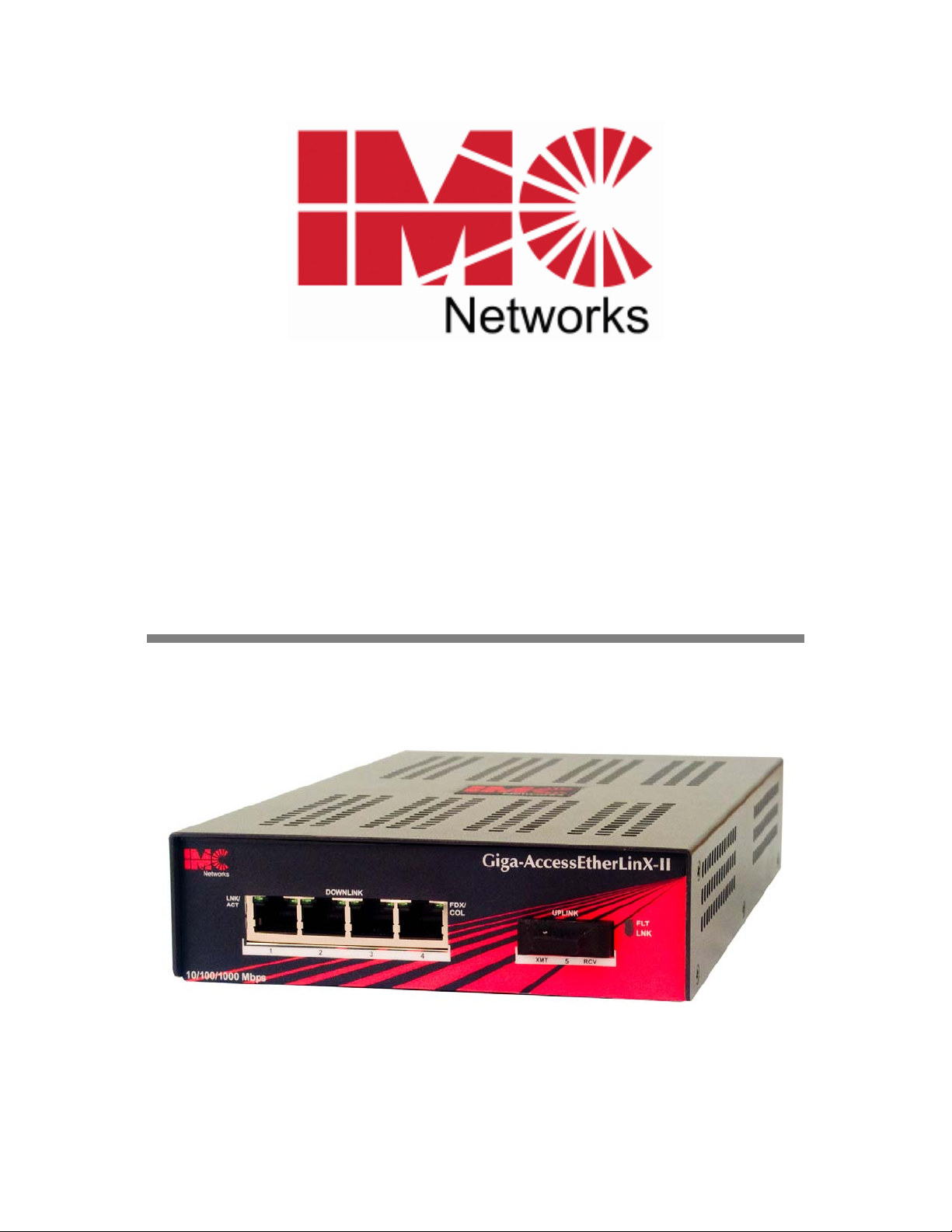
Giga-AccessEtherLinX-II
Operation Manual
The above illustration is representative; some minor differences may be present in actual product
Page 2

FCC Radio Frequency Interference Statement
This equipment has been tested and found to comply with the limits for a Class A computing device, pursuant to Part 15 of the FCC Rules.
These limits are designed to provide reasonable protection against harmful interference when the equipment is operated in a commercial
environment. This equipment generates, uses and can radiate radio frequency energy and, if not installed and used in accordance with the
instruction manual, may cause harmful interference to radio communications. Operation of this equipment in a residential area is likely to
cause harmful interference in which the user will be required to correct the interference at his own expense.
Any changes or modifications not expressly approved by the manufacturer could void the user’s authority to operate the equipment.
The use of non-shielded I/O cables may not guarantee compliance with FCC RFI limits. This digital apparatus does not exceed the Class A
limits for radio noise emission from digital apparatus set out in the Radio Interference Regulation of the Canadian Department of
Communications.
Le présent appareil numérique n’émet pas de bruits radioélectriques dépassant les limites applicables aux appareils numériques de classe A
prescrites dans le Règlement sur le brouillage radioélectrique publié par le ministère des Communications du Canada.
Warranty
IMC Networks warrants to the original end-user purchaser that this product, EXCLUSIVE OF SOFTWARE, shall be free
from defects in materials and workmanship under normal and proper use in accordance with IMC Networks' instructions
and directions for a period of six (6) years after the original date of purchase. This warranty is subject to the limitations set
forth below.
At its option, IMC Networks will repair or replace at no charge the product which proves to be defective within such
warranty period. This limited warranty shall not apply if the IMC Networks product has been damaged by unreasonable
use, accident, negligence, service or modification by anyone other than an authorized IMC Networks Service Technician
or by any other causes unrelated to defective materials or workmanship. Any replaced or repaired products or parts carry
a ninety (90) day warranty or the remainder of the initial warranty period, whichever is longer.
To receive in-warranty service, the defective product must be received at IMC Networks no later than the end of the
warranty period. The product must be accompanied by proof of purchase, satisfactory to IMC Networks, denoting
product serial number and purchase date, a written description of the defect and a Return Merchandise Authorization
(RMA) number issued by IMC Networks. No products will be accepted by IMC Networks which do not have an RMA
number. For an RMA number, contact IMC Networks at PHONE: (800) 624-1070 (in the U.S and Canada) or (949) 4653000 or FAX: (949) 465-3020. The end-user shall return the defective product to IMC Networks, freight, customs and
handling charges prepaid. End-user agrees to accept all liability for loss of or damages to the returned product during
shipment. IMC Networks shall repair or replace the returned product, at its option, and return the repaired or new
product to the end-user, freight prepaid, via method to be determined by IMC Networks. IMC Networks shall not be
liable for any costs of procurement of substitute goods, loss of profits, or any incidental, consequential, and/or special
damages of any kind resulting from a breach of any applicable express or implied warranty, breach of any obligation
arising from breach of warranty, or otherwise with respect to the manufacture and sale of any IMC Networks product,
whether or not IMC Networks has been advised of the possibility of such loss or damage.
EXCEPT FOR THE EXPRESS WARRANTY SET FORTH ABOVE, IMC NETWORKS MAKES NO OTHER WARRANTIES,
WHETHER EXPRESS OR IMPLIED, WITH RESPECT TO THIS IMC NETWORKS PRODUCT, INCLUDING WITHOUT
LIMITATION ANY SOFTWARE ASSOCIATED OR INCLUDED. IMC NETWORKS SHALL DISREGARD AND NOT BE
BOUND BY ANY REPRESENTATIONS OR WARRANTIES MADE BY ANY OTHER PERSON, INCLUDING EMPLOYEES,
DISTRIBUTORS, RESELLERS OR DEALERS OF IMC NETWORKS, WHICH ARE
INCONSISTENT WITH THE WARRANTY SET FORTH ABOVE. ALL IMPLIED WARRANTIES INCLUDING THOSE OF
MERCHANTABILITY AND FITNESS FOR A PARTICULAR PURPOSE ARE HEREBY LIMITED TO THE DURATION OF THE
EXPRESS WARRANTY STATED ABOVE.
Every reasonable effort has been made to ensure that IMC Networks product manuals and promotional materials
accurately describe IMC Networks product specifications and capabilities at the time of publication. However, because of
ongoing improvements and updating of IMC Networks products, IMC Networks cannot guarantee the accuracy of printed
materials after the date of publication and disclaims liability for changes, errors or omissions.
Page 3

Table of Contents
FCC Radio Frequency Interference Statement .........................................................i
Warranty.................................................................................................................i
About the Giga-AccessEtherLinX-II .........................................................................1
Installing the Giga-AccessEtherLinX-II ....................................................................1
Rackmount Installation ...........................................................................................2
Features .................................................................................................................2
About iView² Unit Management.............................................................................4
Utility iConfig.........................................................................................................4
SNMP, Telnet and Console Management ...............................................................5
Main Configuration Screen.....................................................................................6
Configuring VLANs...............................................................................................11
Using Management ..............................................................................................27
UMA (Unified Management Agent) ......................................................................27
LED Operation.....................................................................................................29
Passwords ............................................................................................................30
DC Power Supply Wiring Instructions...................................................................31
Rackmount Precautions........................................................................................32
DC Power Supply Precautions..............................................................................33
Specifications .......................................................................................................34
IMC Networks Technical Support.........................................................................34
Fiber Optic Cleaning Guidelines...........................................................................35
Electrostatic Discharge Precautions.......................................................................35
Safety Certifications..............................................................................................36
ii
Page 4

About the Giga-AccessEtherLinX-II
The Giga-AccessEtherLinX-II Series enables service providers to offer differentiated
data networking or
VPN services to multi-tenant building and business customers.
Residing at the customer premises or at the service provider POP, GigaAccessEtherLinX-II provides
a VLAN-based Layer 2 entry point to the MAN fiber
network, trunking, differentiating and grooming customer traffic. Featuring remote
SNMP management,
prioritization and
port bandwidth control, QinQ support, QoS, traffic
multicast pruning (using IGMP v1, v2), it is an ideal solution for
delivering Ethernet-based services to customers quickly and cost-effectively.
Giga-AccessEtherLinX-II offers configuration access via Telnet, console, secure IP-Less,
and SNMP management channels. Software upgrades can be initiated via any one of
these access methods.
The Giga-AccessEtherLinX-II includes
10/100/1000 twisted pair) and
four 10/100/1000 Mbps twisted pair Ethernet
one Uplink port (either 1000Base-FX fiber or
Downlink Ports for connecting users/LANs, and supports jumbo frame sizes of up to
9600 bytes.
The Giga-AccessEtherLinX-II offers various wavelengths for SM and MM fiber at
gigabit speed; single-strand and SFP versions are also available. As a standalone unit,
it is available in an internal AC or DC version.
Installing the Giga-AccessEtherLinX-II
The Giga-AccessEtherLinX-II comes ready to install; there is no hardware
configuration required. All features, such as management access, qualified VLAN
tags, Link Fault Pass-Through and Auto Negotiation are software configurable.
Place the Giga-AccessEtherLinX-II on a flat surface, prior to installation. Attach the
cables between the Giga-AccessEtherLinX-II and each device that will be
interconnected and then plug the unit into a reliable power source.
1
Page 5

Rackmount Installation
The Rackmount kits for the Giga-AccessEtherLinX-II are sold separately:
Description Part
Accessories Installation
Number
19" Rackmount
brackets
19" Rackmount
shelf
895-39226
895-39949
Includes two brackets
that screw onto either
side of the
AccessEtherLinX-II
Fits into the 19" rack
and holds up to 3 units
of the
AccessEtherLinX-II
Giga-
.
Giga-
.
The brackets are
attached to the unit and
then the
AccessEtherLinX-II
installed into the rack.
The
can be secured to the
II
shelf.
Giga-
is
Giga-AccessEtherLinX-
INSTALLATION TIP
Single-strand fiber products use optics that transmit and receive on two different
wavelengths. Single-strand fiber products must be deployed in pairs, connecting two
compatible single-strand fiber products. Connect the 852-10310 (1310 xmt and 1550 rcv),
for example, to a product with 1550 xmt and 1310 rcv, e.g., 852-10311 (1550 xmt and
1310 rcv.) The two connected products must also have the same speed and distance
capabilities (i.e. both are single-mode [20 km] or both are single/PLUS [40 km]).
Features
Two Layer Qualified Q-in-Q Support
Each drop port can be assigned two different VLAN tags to incoming frames based on
the frames PRI or DSCP priority value and IP or Non-IP Frames types. In this way,
incoming traffic to the network can be groomed into different VLAN tributaries before
entering the network.
AutoCross Feature for Twisted Pair Connection
All twisted pair ports on the Giga-AccessEtherLinX-II include AutoCross, a feature
which automatically selects between a Crossover workstation or Pass-Through
connection depending on the connected device.
Software Configurable Features
The Link Fault Pass-Through, Selective Advertising, as well as Qualified VLAN tags
and Bandwidth Control features are all configurable via the SNMP IP-Less
management, DB-9 console configuration or Telnet session.
2
Page 6

IP-Less Management in HOST/REMOTE configurations
A proprietary, secure management communication channel is supported whenever
the Giga-AccessEtherLinX-II unit is connected directly to an iMcV-GigaFiberLinX-II
unit over the Fiber Uplink. This secure communication channel does not require any
pre-configuration or IP address assignment. It automatically establishes an integrated
Host-Remote management connection between these units, allowing them to be
managed as a single unit, as long as the iMcV-Giga-FiberLinX-II unit is set to a unit via
the DIP Switch setting.
Priority Queuing and Flow Control
The unit supports two different priority queuing schemes. In all modes that do not
allow frame qualification, Priority Queuing is set globally for all ports as a Unit
Control Setting. For modes supporting Qualification, high priority is set individually
per port by the Qualification setting. Frames qualified as high priority will be given
preference over low priority frames to egress the unit.
When internal congestion occurs and the unit is low on internal buffer space, only
high priority frames will be allowed to enter the unit. If Flow Control is enabled,
PAUSE frames will be sent to all ports causing the congestion. If PAUSE frames are
received on a port, that port will not transmit frames until the PAUSE condition has
expired.
Auto Negotiation, Duplex Mode and Speed
The twisted pair ports on the Giga-AccessEtherLinX-II Auto Negotiate for speed and
duplex mode. This device can also selectively advertise or force the speed and
duplex mode. If the device has a fiber Uplink port, it always operates at 1000 Mbps
full-duplex and supports Auto Negotiation on the fiber segment.
Forcing the Speed and Duplex Mode
The twisted pair Downlink Ports on the Giga-AccessEtherLinX-II can also be manually
set for 10, 100, or 1000 Mbps operation and for half- or full-duplex mode (note:
1000 Mbps only supported in full duplex).
Selective Advertising
Selective Advertising, when used in combination with Auto Negotiation, advertises
only the configured speed and duplex mode for the twisted pair port.
If a specific speed and/or duplex mode is desired, use Selective Advertising, rather
than a Force Mode, when connecting to devices that ONLY auto negotiate.
Bandwidth Control
The Giga-AccessEtherLinX-II includes bandwidth control functionality. A maximum
bandwidth can be set independently on each port for both receive and transmit
directions.
3
Page 7

About iView² Unit Management
iView² is a network management application for IMC Networks’ intelligent
networking devices. It features a GUI, which provides network managers the ability
to monitor and control IMC Networks’ products. The application is available in
several versions including Web-Server version 3.0 and can also function as a snap-in
module for HP OpenView Network Node Manager.
iView² supports the following platforms:
• Windows NT
• Windows 2000
• Windows XP
• Windows 7
• Windows Vista
Utility iConfig
iConfig is an in-band utility created by IMC Networks, used for SNMP configuration
for IMC Networks’ SNMP-manageable devices.
The iConfig feature allows the following to be performed:
• Set an IP address, subnet mask and default gateway
• Define community strings and SNMP traps
iConfig also includes an authorized IP address system and restricted access to MIB
groups which are supported by IMC Networks’ manageable devices. These extra
layers of security do not affect SNMP compatibility. iConfig can upload new versions
of the system software and new MIB information. It also includes diagnostic
capabilities for faster resolution of technical support issues.
Default Username/Password
The default user ID and password for both iConfig and Telnet are the following:
User: admin / Password:admin
4
Page 8

SNMP, Telnet and Console Management
SNMP, Telnet, and iConfig management channels are always supported through the
Giga-AccessEtherLinX-II Uplink Port. This provides a higher level of security so end
users cannot access management, alter settings, etc. Management through other
ports can be supported through unit configuration.
In order for the Giga-AccessEtherLinX-II to support SNMP management, the unit must
be assigned IP configuration information (e.g., IP address, subnet mask, etc.) There
are five ways to do so:
• Using iConfig (IP-Less on same Ethernet Domain)
• Host-Remote IP-Less from an iMcV-GigaFiberLinX-II
• Using the console DB9 port located on the back of the unit
• Using DHCP (Dynamic Host Control Protocol); DHCP must be enabled
through the console configuration or Telnet
• Telnet (Default IP=10.10.10.10; subnet mask=255.0.0.0)
In addition to assigning an IP Address and subnet mask, the end user can create
community strings, assign access rights, and configure traps for total remote
management.
About Console Port Configuration
Use the console DB-9 port on the back of the unit to access the internal Command
Line Interface (CLI).
To connect the Giga-AccessEtherLinX-II to a terminal/computer, use a straightthrough (pin-to-pin) cable. (If the computer/terminal has a COM port using a
connection not compatible with a DB-9 connector, use the pin connection chart
shown below for reference in making a cable.) Make sure the cable length is less
than 50 feet (15.24m). Plug one end of the cable into the DB-9 connector and the
other into the appropriate computer/terminal port. Set the computer/terminal for
100 emulation
control
.
, with:
38.4K baud, 8 data bits, 1 stop bit, no parity
and
no flow
VT-
Console RS-232 Interface
DB-9 Pin # Function
2 Transmit (OUT)
3 Receive (IN)
5 Ground
1, 4, 6 - 9 Reserved
5
Page 9

Main Configuration Screen
After running through an initial self test, the screen will display: Press
Configuration. Press
Enter
to be taken to the main configuration screen.
The Main Configuration screen contains the following:
Enter
for Device
Saved Values
— displays changes made during current session.
• IP Address (Should be assigned during initial configuration)
• Subnet Mask (Should be assigned during initial configuration)
• Default Gateway
Current Values
— displays values currently in use.
• IP Address (IP address of SNMP agent)
• Subnet Mask (mask to define IP subnet agent is connected to)
• Default Gateway (default router for IP traffic outside subnet)
Command List
• I
• P
• T
• K
• C
• U
• D
• E
• Space Bar
= Enter New Saved Parameter Values
= Change Password
= New Trap Destination
= Remove ALL Trap Destinations
= New Community String
= Delete ALL Community Strings
= Enable/Disable DHCP
= End Session
= Opens device specific configuration options
6
Page 10

NOTE
Reboot after making any modifications to the Saved Values or the changes will not take
effect. To reboot, type
chassis power OFF, then ON again.
Reboot
at the prompt on the main configuration screen, or turn the
Because a Delete key is not available on VT-100 terminal emulators, use the F2 key instead.
I
Assigning IP Information
To modify the Saved Parameter Values (i.e., assign IP address and subnet mask), press
I
. Enter the IP address and subnet mask for the connected device, pressing
Enter
after each value. A default gateway can also be assigned (press
Enter
finished, press
and then type
Reboot
for the changes to take effect. The Saved
to skip). When
Enter
Values and Current Values should now both display the changes made (e.g., new IP
address and subnet mask).
P
Change Password (only if logged in via console port)
By default, no password is assigned via the console port. However, one can be
assigned by pressing
P
from the main configuration screen. Enter a password;
passwords are case sensitive and should be no more than eight characters in length,
Enter
with no spaces; press
remove password protection, select
. This will be requested whenever logging on or off. To
P
and instead of entering a password press
Enter
.
Passwords are a way to make the management of network devices secure. It is the
responsibility of the network administrator to store and maintain the password lists.
T
Assigning Trap Destinations
Traps are sent by the manageable device to a management PC when a certain event
T
takes place. To enter a trap destination, press
Address, type the IP address of the destination device and press
. When asked to Enter a New IP
Enter
. Then, type
the name of the community string (that the destination device has been configured to
accept) and press
Enter
. This function enables ALL of the device’s traps. To
selectively activate and de-activate traps, use iConfig for configuration. Supported
traps include enterprise-specific and generic; generic traps include: Link Down, Link
Up, Cold Start, Warm Start and Authentication Failure.
K
Removing Trap Destinations
To remove all trap destinations, press K. When asked to confirm, press Y to continue
N
to abort. Then, press
or
C
Creating Community Strings
Enter
.
The purpose of community strings is to add a level of security to a network. The
default community string is named public and has read/write access. Add the
necessary custom community strings such as one with read-only access (for general
use), and another with read/write access (for the administrator), then delete the
7
Page 11

default public string. To create a new community string, go to the main configuration
C
screen and press
spaces) and press
. Enter the name of the new community (up to 16 characters, no
Enter
. Then type one of the following to assign the community
string’s access rights:
R
= read-only access
= read/write access
W
= abort
Enter
Enter.
Press
When finished, press
Enter
and then type
Reboot
for changes to take
effect. The Saved Values and Current Values should now both display the changes
made (e.g., new IP address and subnet mask).
U
Deleting Community Strings
To delete all community strings and start over, press U. When asked, Are you sure
you want to delete all future strings?, press
to proceed or N to abort. Press
Enter
.
Y
This function will delete ALL community strings. Use iConfig to selectively delete
community strings.
D
About DHCP
DHCP Disable (Static IP Addressing)
DHCP is disabled in the default configuration. Initially, modules are assigned
a Static default IP Address of 10.10.10.10. Changes to the Static IP Address
can be added manually through iConfig, an RS-232 Console session, or
Telnet. The changes will be initiated following reboot of the module.
DHCP Enable (Dynamic IP Addressing)
If a DHCP server is present on the network and DHCP is enabled, the DHCP client
will initiate a dialogue with the server during the boot up sequence. The server will
then issue an IP address to the management card. Once the new IP address is
received, the SNMP Management Module will reboot so that the new IP address will
take effect. Refer to the
About Console Port Configuration
for more information
about Enabling/Disabling DHCP. When there is no DHCP server on the network, use
iConfig or console configuration to manually set the IP addresses.
When DHCP is enabled, the IP address (default 10.10.10.10 or user configured) is
saved. When DHCP is disabled, the saved IP address will be reinstated and the
device will reboot.
DHCP servers give out lease times: devices renew their leases based on the
administrator-specified time. If a device cannot renew its lease, and the lease
expires, the device will be given the IP address 10.10.10.10 and will reboot.
8
Page 12

E
Ending a Session
Be sure to press E before disconnecting the cable in order to stop the continuous
stream of data to the console port.
Space Bar Device-Specific Configuration Options
The Giga-AccessEtherLinX-II also includes several device-specific options. To access
these options, press the
Spacebar
from the Command List section of the Main
Configuration screen, type the name of the action you want to perform (as shown
Enter
below) and press
.
ifstats
rmstats
Displays Per Port Ethernet statistics such as port status and congestion.
Displays Per Port RMON statistics such as frame and error counters.
9
Page 13

cleandb
download
Reboots the Giga-AccessEtherLinX-II with a clean database. This
removes all of the information in the database with an option to
change the IP address of device.
Opens the Download dialog from which you download firmware in
the Main Configuration screen using TFTP protocol.
version
vlan
reboot*
accounts
unit
port
bw
sysdescr
Displays the Giga-AccessEtherLinX-II serial number and build date.
Displays and changes VLAN settings (see Configuring VLANs)
Reboots the unit
Allows addition/deletion of Username/Password accounts.
Administrators must maintain a password list.
Unit Global Settings
Displays port status values and allows some configuration (See Port
Configuration section)
Bandwidth Limiting Controls
Allows the editing of sysName, sysDescr, and Port information
text. These entries are used to identify SNMP traps generated
by this unit.
10
Page 14

*A
reboot
may be required for some configuration changes to take effect.
Downloading Files
Firmware and configuration files for the Giga-AccessEtherLinX-II can be downloaded
from a central server via TFTP protocol. Initiate this download via console
configuration or Telnet session. To download a file, type
download
and press
Enter
to be taken to the Download a file screen. This screen displays the IP Address of the
TFTP server and the name of the file to be downloaded. The TFTP server should be
open. Make sure the IP Address and the name of the file are correct.
Configuring VLANs
The Giga-AccessEtherLinX-II is VLAN compatible, with the ability to accept traffic
containing 802.1q VLAN tags on the Uplink port and direct that traffic to the
Downlink Ports where the tag is removed on egress. For even greater flexibility, each
port can be individually configured as an Uplink TRUNK port or as a Downlink
DROP port. Every downlink port can qualify the incoming Ethernet frame and assign
one of two different VLAN tags depending on the priority of the incoming frame.
Qualified VLAN Settings
Incoming frames can be qualified based on the PRI value found in its VLAN tag or on
the DiffServ value found in the IP header of the frame.
Pre Configured Modes
To help alleviate the complexity associated with this, the Giga-AccessEtherLinX unit
has provided eight different modes of operation. Each mode is designed to support a
common customer application to help simplify the configuration process. The
following is a short summary of each mode.
Mode 1
Forwards only untagged frames. Management only accepted from the
Uplink Port.
Mode 2
Forwards both tagged and untagged frames with management only
accepted from Uplink Port. Management domain can flow to Downlink
Ports and can be assigned a VLAN. This is the default mode and
functions as a normal MAC layer switch.
Mode 3
Mode 4
Forwards both tagged and untagged frames with management only
accepted from Uplink Port. Management domain is blocked from
Downlink Ports and can be assigned a VLAN.
Allows fixed port-based forwarding. The user-configured virtual
11
Page 15

connection between ports includes management. Management can be
assigned a VLAN.
Mode 5
Mode 6
Mode 7
Mode 8
Only accepts untagged traffic at the Downlink Ports. All Uplink traffic is
tagged. Each Downlink Port adds a Qualified or Not Qualified VLAN tag
to all ingress traffic. Management only accepted from Uplink Port and
can be assigned a VLAN.
Accepts both tagged and untagged traffic at the Downlink Ports. All
Uplink traffic is tagged. Each Downlink Port adds a Qualified or Not
Qualified VLAN tag to all ingress traffic. Management only accepted
from Uplink Port and can be assigned a VLAN.
Allows each port to be defined as a Drop or a Trunk port. Each Drop
port assigns a Qualified or Not Qualified VLAN-tag to all ingress traffic.
Assigned VLAN tags are added to the packet when they exit a Trunk port.
Management is accepted on any Trunk port and can be assigned a VLAN.
Allows up to 64 VLAN IDs to be defined. Each port can be a tagged or
no-tag member of a defined VLAN. A tag member ports will allow these
tagged frames to enter/exit the port. No-tag members’ ports will add this
tag to assigned frames at egress. NOTE, only one No-tag VLAN can be
assigned to a given port but any or all defined tags can be assigned as tags
for a given port.
To configure VLAN IDs, press the
Spacebar
when in the Command List section of the
Main Configuration screen (console configuration). VLAN is an available option.
vlan
Type
and press
Enter
for VLAN Configuration.
VLAN Mode Screen
When accessing
vlan
in the Main Task Screen, the current VLAN mode is displayed.
The first screen for each mode provides an overview and features of that mode, as
well as instructions on how to proceed through the mode or return to the previous
menu.
12
Page 16

Mode 1—Untagged Frames Only
In this mode, the unit functions as a managed MAC layer switch with management
only accepted on the fiber Uplink and no VLAN support.
Mode 2—Mixed Tagged and Untagged Frames (Default)
When Management can be VLAN tagged, the following screen is given for
configuration.
13
Page 17

Mode 3— Mixed Tagged and Untagged, Block MGMT Domain
14
Page 18

Mode 4— Port Based Forwarding
Port Based Forwarding selection is done on the following screen:
Mode 5—Port Based VLANs
Only untagged frames are delivered to the Downlinks.
15
Page 19

Each port can assign two different VLANs based on the ingress frame classification.
For untagged frames, the DiffServ priority value of the IP frame can be used for
classification. This screen allows the user to select any of the 64 values. In addition
the user must identify whether non-IP frames are also classified.
16
Page 20

Mode 6—Port Based Extra Tag
In this mode both untagged and tagged frames can enter the drop ports.
Two VLANs per port can be assigned based on ingress frames
17
classification.
Page 21

In this mode both tagged and untagged frames can enter the drop port. Tagged
frames can now be classified based on the PRI value within the incoming VLAN tag.
Any PRI value can be used to classify the frame.
18
Page 22

Mode 7— Port Based Extra Tag, Infrastructure
19
Page 23

Mode 7 allows the user to define whether a port is a Trunk (passes everything,
including management), or a Drop (can add/remove VLAN tags). Unit management
is also enabled through any Trunk port.
Once a port is defined as a Drop Port, additional screens are provided to assign
VLAN values based on the classification of the incoming frame.
20
Page 24

Mode 7 also allows the user to define whether PRI or DiffServ values are used to
classify incoming frames and whether non-IP frames are classified. Classification is
done on a port-by-port basis.
21
Page 25

Mode 8—VLAN Assigned
Mode 8 allows up to 64 VLAN IDs to be defined. Each port can be a tags or No-tags
member of a defined VLAN. A tags member port will allow these tagged frames to
enter/exit the port. A No-tags member port will add this frame at egress. Only one
No-tag VLAN can be assigned to a given port, but any or all defined tags can be
assigned as tags for a given port.
Mode 8 allows total flexibility by combining both Trunk and Drop port capabilities
allowing both VLAN filtering and tagging on the same unit.
22
Page 26

Only one No-tags can be assigned to a port; this indicates that all frames entering the
port that do not match the assigned members VLAN-ID list are given this indicated
tag. All frames leaving the port with this tag will have it removed. Assigned tag
frames (tags) will pass through this port without changes.
Unit Control Settings
Global unit settings are configured on this screen and apply to all ports.
Unit Loopback loops all frames entering the fiber Uplink Port back to the fiber port.
Unit Max Frame Size can be set as high as 12.2K Bytes. However, the unit can not
sustain a continuous stream of this jumbo frame without some frames loss. Sustained
MAX frames size with no frame loss is limited to 8.2K bytes.
802.1p Base Priority is a value from 0 to 7 that is used to divide incoming frames into
High and Low priority groups. A Base Value of 4 indicates that any VLAN tag with
4 will be given High Priority status inside the unit, is applicable to Modes
PRI>
2,3,and 4 only.
The unit can be configured to Block Bridge, GARP, and All Bridge protocol frames.
23
Page 27

Bandwidth Limiting
Bandwidth Limiting can be set per port in both transmit and receive directions. The
limiting function provides a Leaky Bucket traffic shaping function when placed on the
TX side of a port. When the transmit limit is reached on a port, it will stop
transmitting until the bucket level falls below the set level. When placed on the RX
side it functions more like a hard Bandwidth limiter. When the Bucket level is
reached, the port will stop receiving frames and will issue PAUSE frames back to the
port until this bucket level clears.
Bandwidth Limiting is entered as any value from 0 to the MAX bandwidth of the port.
24
Page 28

Port Configuration
The Giga-AccessEtherLinX-II Downlink Ports can be configured via console
configuration. Type
and press
Enter
to be taken to the Port Configuration
ports
screen. From this screen, users can enable/disable ports and set Auto Negotiation
and Flow Control functions, etc. (This can also be performed via iView².)
When a port is disabled, it will no longer show LINK or send any traffic to the port.
Flow Control will cause a port to send PAUSE whenever the ports internal buffer
space is low. This can be affected by both Bandwidth limit setting for the port and
traffic congestion on the port.
Forced Flow Control should only be used when the connected end device does not
support Auto Negotiation.
25
Page 29

System Descriptions
This screen allows the user to define unit and port names that are incorporated by the
unit into all SNMP traps. These are extremely useful in troubleshooting the system.
Firmware and Unit Version Information
To help maintain Software revision control, these reference numbers are always
updated whenever unit software is downloaded to the equipment.
26
Page 30

Using Management
iView² is a network management application for IMC Networks intelligent
networking devices. It features a GUI and gives network managers the ability
to monitor and control products from a variety of platforms.
Using iView² with HP OpenView
During the installation, the iView² application will ask if HP OpenView is
installed on the management PC. Click Yes to integrate the appropriate files.
Once in OpenView, highlight the media converter icon and select the media
converter; OpenView will then launch iView².
Other NMS Applications
If using an application other than iView² for management, integrate the
SNMP vendor MIBs, which can be found in the MIB subdirectory of iView²
installed on the chosen hard drive of a workstation.
Refer to the application's documentation for information on how MIB files
are integrated.
Update Manager
iView² offers the option of scheduling an update search for IMC Networks devices
listed in the Network outline. Within iView², select
navigation toolbar. Select
Update Manager Options
Tools/SNMP Options
, and a dialog box will be
from the
displayed, in which you can select when to run the update search. This option
enables the end user to determine if they have the latest firmware, and download the
latest if they do not. It does not automatically run the download, so the end user can
review the release notes included with the binary file, and decide whether to
download it or not.
UMA (Unified Management Agent)
The UMA allows operators to manage all IMC Networks modules with on-board logic
(iMcV-GigaFiberLinX-II series) installed in an IMC Networks iMediaChassis, with a
single IP address from a central location. Centralized management makes practical
sense for networks of all sizes, especially service provider networks that must monitor
and upgrade large quantities of devices. In addition, UMA allows users to centrally
manage and administer firmware upgrades over multiple devices.
For example, the user can install ten iMcV-Giga-FiberLinX-II devices in a 20 slot
iMediaChassis at the Central Office (CO) and connect each to a remote GigaAccessEtherLinX-II unit installed at the customer’s premises equipment (CPE). UMA
allows users to manage all 20 devices (including the chassis at the CO) via the single
27
Page 31

IP address assigned to the chassis management card. Users may still assign IP
addresses to each iMcV-Giga-FiberLinX-II and Giga-AccessEtherLinX-II, and manage
them independently over the network being transported but this may not provide the
same level of security as the UMA system.
With the Unified Management Agent
When an SNMP request for an iMcV-Giga-FiberLinX-II comes in, the SNMP
Management Module in the iMediaChassis passes the request to the SNMP agent in
the specific module. The SNMP agent in the iMcV-Giga-FiberLinX-II provides the
relevant management information for both the iMcV-Giga-FiberLinX and the remote
Giga-AccessEtherLinX-II unit using a secure IP-Less messaging channel to the remote
unit.
IP-Less Management
The Giga-AccessEtherLinX-II supports the IMC Networks secure management system
that allows the unit to function as an integrated remote unit when attached to a GigaAccessEtherLinX-II Host unit over a fiber link segment. In this mode the two units are
managed as one integrated pair without the need of an assigned IP address at the
remote unit.
File Management for Upgrading
The following screen, located in the iConfig utility of iView², shows the File
Management functionality of the Unified Management Agent. Operators can easily
upload and store new firmware versions for upgrading multiple devices with on-board
logic installed in, or connected to, an iMediaChassis.
28
Page 32

Using Telnet
Assign the Giga-AccessEtherLinX-II an IP Address or use the default IP Address
10.10.10.10, subnet mask 255.0.0.0 before using a Telnet session. All configurations
done via the console port can also be performed using Telnet. The user should only
open one Telnet or RS232 console session at a time. Do not use an RS232 console
session and a Telnet session at the same time as unexpected results may occur.
LED Operation
Downlink Ports
LNK/ACT Glows green when link is established on port.
Blinks green during data activity on port.
FDX/COL Glows green when port is operating in Full-Duplex.
Blinks green when collisions occur on port.
No display when port is operating in HDX
29
Page 33

Uplink Ports
FLT Glows yellow when a fault is detected with the fiber Uplink. Faults
include loss of link and half-duplex operation. Half-duplex is not
defined for a fiber line running at gigabit rates.
LNK Glows green when link is established.
Blinks green during data activity.
Passwords
If the username and password are available when accessing iView², the unit can be
reset back to its original factory setting with the following procedure. Open a console
session by launching a Hyperterminal session with the unit. Upon completion of the
boot sequence, press the
Spacebar
Upon completion, type in the command
once and then type in the command
reboot
. This will reset the
cleandb
.
username/password back to admin/admin.
If the username and password are lost for the console session, open iConfig within
iView
²
. In the Administration tab, upgrade the PROM with a backup copy of the last
binary file, or load a current binary file downloaded from the IMC Networks
download product page. By reloading the binary file, the username and password is
removed.
If BOTH password accesses are lost, contact
Technical Support
at
1-800-624-1070
for information.
Before using iView²
iView² is a network management application designed for Intelligent Networking
Devices from IMC Networks. It features a GUI and gives network managers the
ability to monitor and control products from a variety of platforms. iView² can also
function as a snap-in module for HP Open View Network Node Manager.
System Requirements
To run iView², the management PC must be equipped with the following:
• 29 MB free disk space, 64 MB RAM
• Windows: NT 4.0 Service Pack 5, 2000 Professional, or XP
• Microsoft SNMP Services Installed
• Microsoft IE 4.0 or Higher (not required as default browser)
• Microsoft IIS required for Web Server version
Java versions require the following:
• 25 MB free disk space, 64 MB RAM
• Any OS capable of running Java (Windows 98 or above, Solaris, LINUX)
• Java Runtime v 1.3
30
Page 34

Strongly recommended:
• 128 MB RAM
• Pentium III 650Mhz or Faster
• 17” Monitor @ 1024 x 768 Resolution or higher
Installing and Using iView²
iView² is available to install as a download at
www.imcnetworks.com/Products/iView.cfm.
When using iView² with HP OpenView
During the installation, the iView² application will ask if HP Open View is installed on
Yes
the management PC. Click
to integrate the appropriate files. Once in
OpenView, select IMC Networks from the toolbar to view the IMC Networks devices.
When Not Using iView
²
When using an application other than iView² for management, integrate the SNMP
vendor files (a.k.a. MIBs) into the application. The SNMP agent uses the following
Enterprise-specific MIB file and standard MIBs, which can be found in the MIB
directory within the iView
Using the IMC MIBs
²
download files.
Refer to the MIBs folder located with the iView² software for product-related MIBs.
DC Power Supply Wiring Instructions
DC Power Supply
If in a -48 environment:
DC Power Supply
If in a +48 environment:
-48
GND
(Common)
Chassis
Gnd
Terminal Block
NOTE
Incorrect wiring will result in chassis malfunction. The Giga-AccessEtherLinX-II (DC) is
compliant with Isolated Grounding Plane practices. The POSITIVE and NEGATIVE terminals
are isolated from chassis ground and must have a ground reference at the power-sourcing
equipment.
31
+48
Chassis
Gnd
Terminal Block
GND
(Common)
Page 35

This equipment is designed to permit the connection of the grounded conductor of
the DC supply circuit to the grounded conductor at the equipment. If this
connection is made, all of the following conditions must be met:
This equipment shall be connected directly to the DC supply system
1.
grounded electrode conductor or to a bonding jumper from a grounded
terminal bar or bus to which the DC supply system grounding electrode
conductor is connected.
This equipment shall be located in the same immediate area (such as,
2.
adjacent cabinets) as any other equipment that has a connection between
the grounded conductor of the same DC supply circuit and the grounding
conductor, and also the point of grounding of the DC system. The DC
system shall not be grounded elsewhere.
The DC supply source shall be located within the same premises as this
3.
equipment.
4.
Switching or disconnecting devices shall not be in the grounded circuit
conductor between the DC source and the point of connection of the
grounding electrode conductor.
Rackmount Precautions
1. Elevated Operating Ambient - If installed in a closed or multi-unit rack
assembly, the operating ambient temperature of the rack environment may
be greater than room ambient. Therefore, consideration should be given to
installing the equipment in an environment compatible with the maximum
ambient temperature (Tma) specified by the manufacturer.
Reduced Air Flow - Installation of the equipment in a rack should be such
2.
that the amount of air flow required for safe operation of the equipment is
not compromised.
Mechanical Loading - Mounting of the equipment in the rack should be
3.
such that a hazardous condition is not achieved due to uneven mechanical
loading.
4.
Circuit Overloading - Consideration should be given to the connection of
the equipment to the supply circuit and the effect that overloading of the
circuits might have on overcurrent protection and supply wiring.
Appropriate consideration of equipment nameplate ratings should be used
when addressing this concern.
5.
Reliable Grounding - Reliable grounding of rackmounted equipment
should be maintained. Particular attention should be given to supply
connections other than direct connections to the branch circuit (e.g., use
of power strips).
32
Page 36

DC Power Supply Precautions
The following precautions must be observed when installing the chassis model with
an internal DC power supply.
Check nameplate ratings to ensure there is no overloading of supply circuits that
1.
could affect over current protection and supply wiring.
In addition, the following must be observed:
2.
Connect the equipment to a 36 to 56.7 V DC power source that is
a.
electrically isolated from the alternating current source.
Nominal
Voltage
Minimum
Voltage
Maximum
Voltage
Transient
Voltage
48 36 56.7 75.0*
* 75.0-V transient with a duration of 10.0 ms with a rate of rise and fall of
10 V/ms. The equipment shall meet its operational specifications during
the transient.
b.
Route input wiring to terminal block and secure in such a manner that it is
protected from damage and stress. Do not route wiring past sharp edges or
moving parts.
Incorporate a readily accessible disconnect device, with a 3mm minimum
c.
contact gap in the fixed wiring.
Install only in Restricted Access Areas (dedicated Equipment Rooms,
d.
Equipment closets or the like) in accordance with Articles 110-18, 110-26,
and 110-27 of the National Electric Code, ANSI/NFPA 70.
e.
Provide a listed circuit breaker suitable for branch circuit protection of the
wiring and rated maximum 1A @ 48 V DC.
For supply connections, use wires suitable for at least 75° C.
f.
33
Page 37

Specifications
Standards
IEEE 802.3x Ethernet
IEEE 802.3u Auto Negotiation
IEEE 802.1q VLAN
IEEE 802.1p Packet Prioritization
Operating Temperature
+32° F to +122° F (0° C to +50° C)
Storage Temperature
-40° F to 185° F (-40°C to 85° C)
Humidity
10 to 95% (non-condensing)
Maximum heat generated
81 BTU/hr
Power Requirements (typical)
100-240V AC, 50/60Hz, 0.5/0.25A for AC
48V DC, 0.5A for DC
Throughput
Up to full wire speed on all ports.
Up to 9600 MTU
Dimensions
Height = 1.64” x Width = 5.64” x Depth = 8.95” (4.2 cm x 14.3 cm x 22.7 cm)
IMC Networks Technical Support
Tel:
(949) 465-3000 or (800) 624-1070 (in the U.S. and Canada);
+32-16-550880 (Europe)
Fax:
E-Mail:
Web:
(949) 465-3020
techsupport@imcnetworks.com
www.imcnetworks.com
34
Page 38

Fiber Optic Cleaning Guidelines
Fiber Optic transmitters and receivers are extremely susceptible to contamination by
particles of dirt or dust, which can obstruct the optic path and cause performance
degradation. Good system performance requires clean optics and connector ferrules.
Use fiber patch cords (or connectors, if you terminate your own fiber) only from
1.
a reputable supplier; low-quality components can cause many hard-to-diagnose
problems in an installation.
Dust caps are installed at IMC Networks to ensure factory-clean optical devices.
2.
These protective caps should not be removed until the moment of connecting
the fiber cable to the device. Should it be necessary to disconnect the fiber
device, reinstall the protective dust caps.
3.
Store spare caps in a dust-free environment such as a sealed plastic bag or box
so that when reinstalled they do not introduce any contamination to the optics.
If you suspect that the optics have been contaminated, alternate between
4.
blasting with clean, dry, compressed air and flushing with methanol to remove
particles of dirt.
Electrostatic Discharge Precautions
Electrostatic discharge (ESD) can cause damage to any product, add-in modules or
stand alone units containing electronic components. Always observe the following
precautions when installing or handling these kinds of products
Do not remove unit from its protective packaging until ready to install.
1.
Wear an ESD wrist grounding strap before handling any module or component.
2.
If the wrist strap is not available, maintain grounded contact with the system unit
throughout any procedure requiring ESD protection.
Hold the units by the edges; do not touch the electronic components or gold
3.
connectors.
After removal, always place the boards on a grounded, static-free surface, ESD
4.
pad or in a proper ESD bag. Do not slide the modules or stand alone units over
any surface.
WARNING!
Integrated circuits and fiber optic components are
extremely susceptible to electrostatic discharge damage. Do not
handle these components directly unless you are a qualified service
technician and use tools and techniques that conform to accepted
industry practices.
35
Page 39

Safety Certifications
UL/CUL: Listed to Safety of Information Technology Equipment, including
Electrical Business Equipment.
CE: The products described herein comply with the Council Directive on
Electromagnetic Compatibility (2004/108/EC) and the Council
Directive on Electrical Equipment Designed for use within Certain
Voltage Limits 2006/95/EC). Certified to Safety of Information
Technology Equipment, Including Electrical Business Equipment. For
further details, contact IMC Networks.
.
Class 1 Laser product, Luokan 1 Laserlaite,
Laser Klasse 1, Appareil A’Laser de Classe 1
European Directive 2002/96/EC (WEEE) requires that any equipment that bears this
symbol on product or packaging must not be disposed of with unsorted municipal
waste. This symbol indicates that the equipment should be disposed of separately
from regular household waste. It is the consumer’s responsibility to dispose of this
and all equipment so marked through designated collection facilities appointed by
government or local authorities. Following these steps through proper disposal and
recycling will help prevent potential negative consequences to the environment and
human health. For more detailed information about proper disposal, please contact
local authorities, waste disposal services, or the point of purchase for this equipment.
36
Page 40

19772 Pauling y Foothill Ranch, CA 92610-2611 USA
y
TEL: (949) 465-3000
FAX: (949) 465-3020
www.imcnetworks.com
© 2011 IMC Networks. All rights reserved.
The information in this document is subject to change without notice. IMC Networks assumes no responsibility for any
errors that may appear in this document. Giga-AccessEtherLinX-II is a trademark of IMC Networks. Other brands or
product names may be trademarks and are the property of their respective companies.
Document Number 52-80321-00 A1 October 2011
 Loading...