

IMCA Mini RadaScan Owner's Manual

Mini RadaScan Microwave
Radar Sensor for Dynamic
Positioning Operations
IMCA M 229
October 2015

The International Marine Contractors Association
(IMCA) is the international trade association
representing offshore, marine and underwater
engineering companies.
IMCA promotes improvements in quality, health, safety,
environmental and technical standards through the publication of
information notes, codes of practice and by other appropriate
means.
Members are self-regulating through the adoption of IMCA
guidelines as appropriate. They commit to act as responsible
members by following relevant guidelines and being willing to be
audited against compliance with them by their clients.
There are two core activities that relate to all members:
Competence & Training
Safety, Environment & Legislation
The Association is organised through four distinct divisions, each
covering a specific area of members’ interests: Diving, Marine,
Offshore Survey, Remote Systems & ROV.
There are also five regional sections which facilitate work on
issues affecting members in their local geographic area –
Asia-Pacific, Central & North America, Europe & Africa, Middle
East & India and South America.
IMCA M 229
This report has been prepared in order to give IMCA members
an overview and review of the Mini RadaScan position reference
sensor as used within dynamic positioning applications.
Mini RadaScan is a microwave radar sensor system which has
gained wide usage within marine offshore operations.
The major part of the document has been prepared by the
manufacturers of this system, Guidance Marine Ltd. It covers the
components of the system, sensor design, operation including
advantages and disadvantages, servicing and maintenance,
applications and technical specification.
www.imca-int.com/marine
The information contained herein is given for guidance only and endeavours to
reflect best industry practice. For the avoidance of doubt no legal liability shall
attach to any guidance and/or recommendation and/or statement herein contained.
© 2015 IMCA – International Marine Contractors Association

Mini RadaScan Microwave Radar Sensor for
Dynamic Positioning Operations
IMCA M 229 – October 2015
1 Preface .................................................................................................................... 1
2 Glossary of Terms ................................................................................................. 2
3 Overview ................................................................................................................. 3
4 Components ........................................................................................................... 4
5 Features .................................................................................................................. 5
5.1 System Advantages ................................................................................................................................................. 5
5.2 System Disadvantages............................................................................................................................................ 5
6 Installation .............................................................................................................. 6
6.1 Sensor Wiring Diagram ........................................................................................................................................ 6
6.2 Sensor Placement ................................................................................................................................................... 6
6.3 Responder Placement............................................................................................................................................ 7
6.4 Calibration ................................................................................................................................................................ 7
7 System Design ........................................................................................................ 8
7.1 Sensor Properties ................................................................................................................................................... 8
7.2 Measurement Principles ........................................................................................................................................ 9
7.3 Responders ........................................................................................................................................................... 11
8 Operation ............................................................................................................. 13
8.1 Dashboard ............................................................................................................................................................. 13
8.2 Multiple Sensor/Multiple Target Operation ................................................................................................. 14
8.3 Mini RadaScan Interoperability and Compatibility ...................................................................................... 14
9 Servicing and Maintenance ................................................................................. 16
9.1 Software Upgrades .............................................................................................................................................. 16
9.2 Recycling and Disposal ....................................................................................................................................... 16
10 Applications .......................................................................................................... 17
11 Operational Experience ...................................................................................... 18
11.1 Co-location/Sensor Placement ........................................................................................................................ 18
11.2 Performance ......................................................................................................................................................... 18
11.3 Responder Angle of Incidence ......................................................................................................................... 20
11.4 Multi-path Accuracy ............................................................................................................................................ 20
11.5 Frequently Asked Questions ............................................................................................................................ 24
11.6 Operational Experience ..................................................................................................................................... 26
12 Specifications ........................................................................................................ 27
12.1 Computer Specifications ................................................................................................................................... 27
12.2 Sensor Specifications .......................................................................................................................................... 27
12.3 Responder Specifications ................................................................................................................................... 28
13 References ............................................................................................................ 29


IMCA M 229 1
1 Preface
Reliable and robust methods of positioning are required for safe vessel operations at offshore installations.
The development of dynamic positioning (DP) systems has been gradual over the past 50 years and today, various
manufacturers’ systems are available around the world.
Every measurement technology is bound by limitations (i.e. physics) and external factors (e.g. signal obstruction,
solar activity, weather, sea conditions, range), which makes it difficult for one technology to cover all applications
with uninterrupted service. Hence the growth in the use of DP has been accompanied by the development of
internationally recognised rules, standards and guidelines against which DP vessels are designed, constructed and
operated.1 2 3
The growth and development of DP systems has stimulated the development of DP position measurement
sensors which have become more sophisticated as technology has allowed. Within the relative position
measurement equipment range the DP market is familiar with the use of laser and microwave sensors.4 5 6 7 This
document describes the Mini RadaScan product, which is part of the range of microwave relative positioning
systems offered by Guidance Marine (see www.guidance.eu.com).
IMCA has published IMCA M 209 – RadaScan microwave radar sensor for dynamic positioning operations. This
document provides an overview of the Mini RadaScan system.
1
IMO MSC Circ. 645 – Guidelines for vessels with dynamic positioning systems
2
IMCA M 103 – Guidelines for the design and operation of dynamically positioned vessels
3
182 MSF – International guidelines for the safe operation of dynamically positioned offshore supply vessels
4
IMCA M 170 – A review of marine laser positioning systems – Part 1: MK IV Fanbeam® and Part 2: CyScan
5
IMCA M 174 – A review of the Artemis Mark V positioning system
6
IMCA M 209 – RadaScan microwave radar sensor for dynamic positioning operations
7
IMCA M 224 – Guidance on RADius relative positioning system

2 IMCA M 229
2 Glossary of Terms
ATEX ATmosphères EXplosibles
CE Conformite Europeenne. Mandatory marking for products sold in the European Economic Area (EEA)
Clutter Radar signal that is echoed back towards the sensor
DAC Digital to analogue converter
Dashboard Graphical user interface used to control the sensor
DGNSS Differential global navigation satellite system
DGPS Differential Global Positioning System
DP Dynamic positioning
DSB Dual side band
DSP Digital signal processing
EMC Electro-magnetic compatibility
FCC Federal Communications Commission. Among many of its functions it specifies the
electromagnetic interference specification for products manufactured or sold in the United States
FMCW Frequency-modulated continuous wave
FSK Frequency shift key
GPS Global Positioning System
HPR Hydroacoustic positioning reference system
I/O Input/output
IMCA International Marine Contractors Association
IMO International Maritime Organization
IP Internet protocol
LAN Local area network
LED Light emitting diode
mrad milli-radians
OSV Offshore supply vessel
PCI Peripheral component interconnect
PSK Phase shift key
PSV Platform support vessel
RAS Replenishment at sea
RCS Radar cross section
Reflection RF signal received by the sensor from the responder
Responder Purpose built hardware unit mounted on a structure, which retransmits a modulated version of
the signal it receives from a Mini RadaScan sensor
RF Radio frequency
RX Received RF signal
Series1 miniResponders that implement FSK-DSB
Series2 miniResponders that implement PSK-SSB
SSB Single side band
Target A processed and positively identified return from a responder
TX Transmitted RF signal
UL Underwriters Laboratories Inc. The leading North American product safety certification
organisation, whose certifications are recognised world-wide
UPS Universal power supply
VFD Vacuum fluorescent display
1 sigma (1σ) Standard deviation is a measure that is used to quantify the amount of variation of a set of data
values

IMCA M 229 3
3 Overview
DP systems using relative position measurement equipment have been used in a wide range of industrial
applications where operation typically requires vessels to perform either:
‘station keeping’; e.g. maintain their position against fixed or moving installations for loading and/or unloading;
‘track and follow’; e.g. maintain the same heading and speed relative to another vessel.
These operations often require sub-metre accurate local reference measurements to be supplied to the DP
system. The Mini RadaScan sensor is a microwave based reference system that has been developed to offer an
accuracy that is comparable to a laser system combined with the capability to work in all weather conditions
where the presence of heavy fog, heavy rain, snow, dust or steam could affect the performance of laser systems.
A typical vessel will utilise a number of sensors simultaneously. Therefore each sensor needs to be capable of
operating without interfering with or suffering interference from other sensors.8
The Mini RadaScan system builds on the success of RadaScan and is one of the latest developments in local
reference sensor technology. The Mini RadaScan is smaller and lighter than the RadaScan, thus making installation
easier and quicker, whilst providing crucial all-weather operation without compromising on accuracy.
Mini RadaScan has the same friendly and familiar user interface as RadaScan.
In the rest of the document, the term sensor will be used to refer to the Mini RadaScan unit unless stated
otherwise.
8
IMCA M 199 – Guidelines on installation and maintenance of DGNSS-based positioning systems
4 IMCA M 229
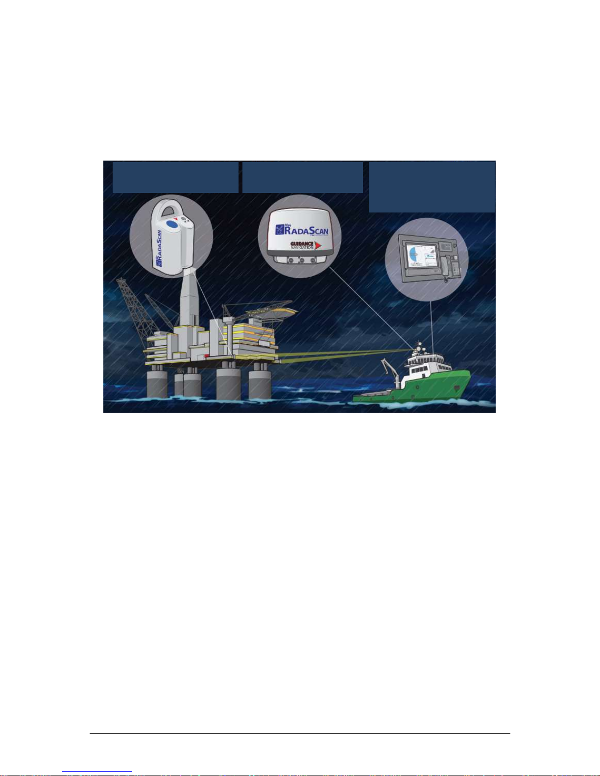
4 Components
A Mini RadaScan system consists of three main components:
a sensor unit for the detection and processing of reflections;
a responder(s) unit, which reflects the signal from the sensor;
a marine computer used to configure and control the sensor using the dashboard software.
System components are shown in Figure 1.
Figure 1 – Mini RadaScan system components
Mini RadaScan Responders (one
or more) that are mounted on the
fixed platform or mobile object
Mini RadaScan Sensor that is
installed on a vessel equipped with
a DP system
Mini RadaScan Console software
is used by the DP operator to
control the Mini RadaScan Sensor. It
runs on a marine computer installed
on the vessel’s bridge

IMCA M 229 5
5 Features
The sensor is a low power (1 watt) all-weather FMCW radar unit operating over a 100 MHz bandwidth in the
licence-free 9.25 GHz maritime radiolocation band. A 360° rotating antenna which is spun at a continuous rate
of 1 Hz provides unrestricted vessel manoeuvrability when trackingF targets, unlike a fixed antenna design.
The sensor works by detecting reflections from one or more ATEX certified responders mounted on a structure
such as an oil rig. The sensor calculates a relative target position which is sent to the DP system and the
dashboard.
A maximum of four responders can be detected by each sensor. They operate in four distinct frequency channels
specifically designed for the sensor and introduce a unique identifying code into the reflection to allow
unambiguous target identification and robust tracking. Each responder can also be used simultaneously by
multiple sensors which allows several vessels to obtain position information at the same time from one set of
responders.
There are two main modes of operation:
Single-target tracking provides target range and bearing measurements. It is mainly used in fixed structure
applications such as drilling rigs and production platforms;
Multi-targets tracking provides target range and bearing measurements and is also capable of calculating
vessel heading. It is mainly used in mobile structure applications such as vessel track and follow.
Once a valid relative position has been calculated, the sensor generates a standard DP telegram every second,
which is compatible with all modern DP systems.
5.1 System Advantages
All-weather operations;
uniquely coded responders ensure reliable tracking;
single or multiple responder capability;
automatic target detection;
full 360° scanning providing an unobstructed field of view;
uses coded responders making the system immune to false reflections;
responders are ATEX certified and intrinsically safe;
compatible with all leading DP systems;
versatile choice of responders to suit all applications (power cell pack powered, mains powered, or
rechargeable battery);
compact and lightweight design for easy transport and installation;
modular design to simplify servicing and maintenance.
5.2 System Disadvantages
Responder location must be selected to ensure line of sight is maintained throughout the operation;
requires the use of manufacturer’s own responders;
like all microwave based sensors, sea reflections can cause problems in still conditions if the
installation instructions are not followed carefully.
6 IMCA M 229
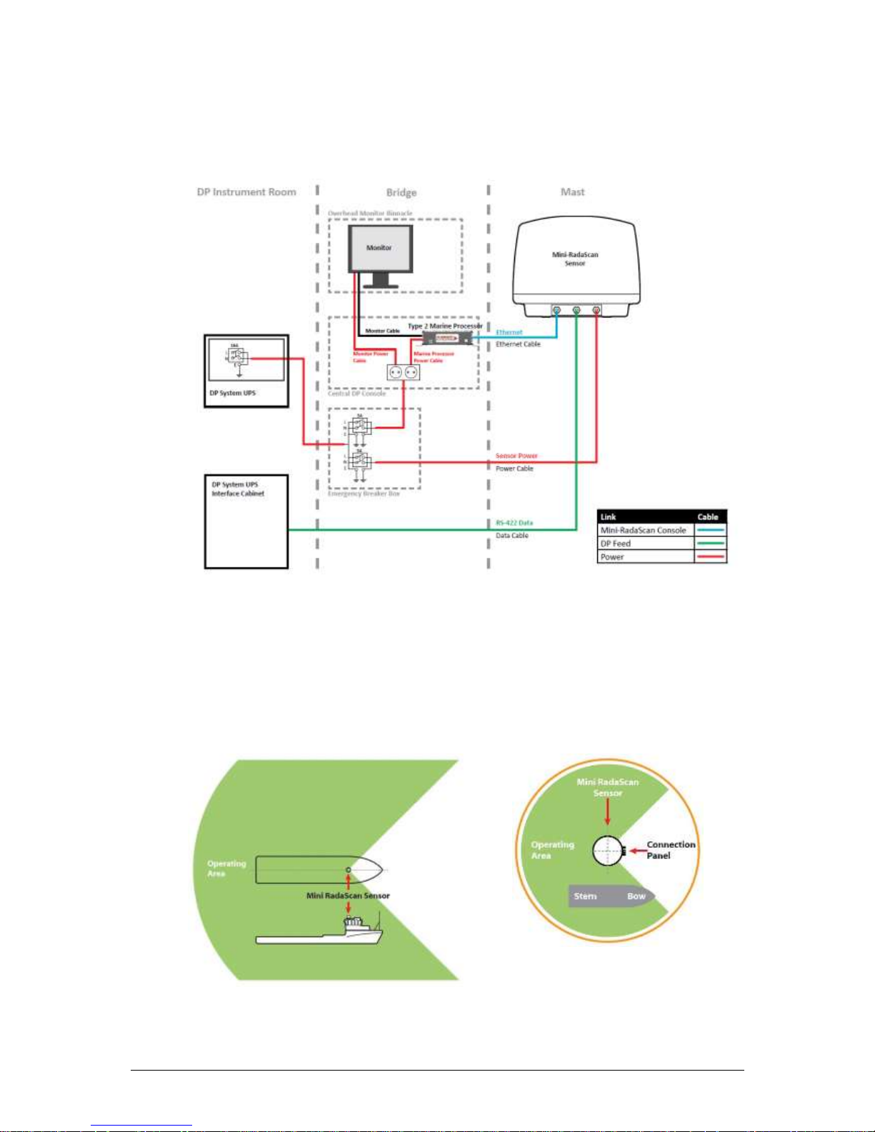
6 Installation
6.1 Sensor Wiring Diagram
The Mini RadaScan installation cable routing is shown in Figure 2.
Figure 2 – Mini RadaScan components cable routing
6.2 Sensor Placement
Sensor placement varies with each application therefore the information hereafter is provided as a
general guideline.
On a platform supply vessel (PSV), the typical mounting position for the sensor is above the wheelhouse,
with a clear view over the aft deck area or whichever operating area is required.
Figure 3 – Typical sensor mounting position covering deck area
 Loading...