

IMC SP Series, SP25, SP12 Installation, Operating And Maintenance Manual

SP-RANGE
SP25 PEELER
SP12 & SP25 – SERIES 4
INSTALLATION, OPERATING AND MAINTENANCE MANUAL
PLEASE LEAVE WITH OPERATOR
A34/013 R17 ECN 8818 February 2019
1 | P a g e

SP-RANGE
EC DECLARATION OF CONFORMITY
(Guarantee of Production Quality)
We, Imperial Machine Company Limited of:
Unit 1, Abbey Road, Wrexham Industrial Estate, Wrexham, LL13 9RF
Declare under our sole responsibility that the machine
SP12 & SP25 – SERIES 4
As described in the attached technical documentation is in conformity with the Machine Safety
Directive 98/37/EC and is manufactured under quality system BS EN ISO 9001. It is also in
conformity with the protection requirements of the Electro Magnetic Compatibility Directive
2004/108/EEC and is manufactured in accordance with harmonised standards EN 61000-6-1
Immunity and EN 61000-6-3 Emissions (plus product specific standards).
It also satisfies the essential requirements of the Low Voltage Directive 2006/95/EC and is
manufactured in accordance with harmonised standard EN 60204-1 Safety of Machinery
(Electrical Equipment).
Approved by E Plumb, Engineering Manager
Signed at Wrexham, Date February 2019
2 | P a g e

SP-RANGE
CONTENTS
GUARANTEE .................................................................................................................... 4
DELIVERY ......................................................................................................................... 4
SAMPLE RATING LABEL.................................................................................................... 4
INTRODUCTION ............................................................................................................... 5
YOUR PEELER ................................................................................................................... 5
CONTROLS ....................................................................................................................... 6
INSTALLATION .......................................................................................................... 6 & 7
WATER SUPPLY ................................................................................................................ 7
WASTE OUTLET CONNECTION ......................................................................................... 7
WASTE EJECTOR .............................................................................................................. 8
ELECTRICITY SUPPLY CONNECTION ........................................................................ 9 & 10
COMMISSIONING .......................................................................................................... 10
OPERATION ................................................................................................................... 10
SAFETY ........................................................................................................................... 11
CLEANING ...................................................................................................................... 11
DO’S AND DON’TS ......................................................................................................... 12
MATERIAL CONTENT...................................................................................................... 12
MAINTENANCE .............................................................................................................. 13
WIRING DIAGRAM 1PH UNITS ....................................................................................... 14
WIRING DIAGRAM 3PH UNITS ....................................................................................... 15
PARTS ILLUSTRATION .................................................................................................... 16
SPARES PART LIST ..................................................................................................17 & 18
1PH CONTROL BOX SPARE PARTS LIST .......................................................................... 19
3PH CONTROL BOX SPARE PARTS LIST .......................................................................... 20
ORDERING SPARE PARTS ............................................................................................... 21
3 | P a g e
SP-RANGE
GUARANTEE
This equipment is guaranteed by IMC for 2 Years from the date of purchase from IMC or from one of
its stockists, dealers or distributors.
The guarantee is limited to the replacement of faulty parts or products and excludes any consequential
loss or expense incurred by purchasers. Defects which arise from faulty installation, inadequate
maintenance, incorrect use, connection to the wrong electricity supply or fair wear and tear are not
covered by the guarantee.
PLEASE OBSERVE THESE INSTRUCTIONS CAREFULLY
This guarantee applies in this form to installations within the UK only.
DELIVERY
The machine is packaged in a carton. Please check the contents against the list below.
Peeler Unit, with lid, control box and mounting bracket 1
Peeling plate 1
Water supply pipe and 2 hose clips 1
1m long 3” flexible waste hose and hose clip 1
Instruction Booklet 1
If any accessories have been ordered they will be supplied in separate packages.
Please notify the carrier and the supplier within three days of receipt if anything is missing or damaged.
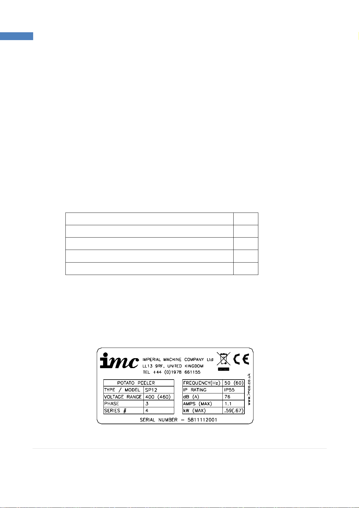
Check that the correct machine has been supplied and that the voltage, marked on the rating plate on
the motor, is suitable for the supply and control voltage available. The rating plate is located at the back
of the cylinder near the supply cable inlet.
SAMPLE RATING LABEL
4 | P a g e
SP-RANGE
INTRODUCTION
This machine is intended for peeling potatoes. Its use may be extended to other root vegetables. It is
not recommended to use this machine for peeling onions.
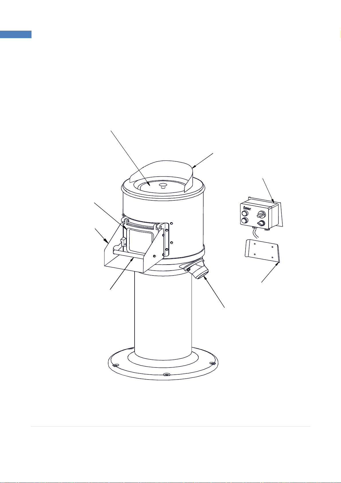
YOUR PEELER
SPLASH COVER
LID
CONTROL BOX
DOOR
CHUTE
MOUNTING BRACKET
DOOR HANDLE
WASTE OUTLET
5 | P a g e
SP-RANGE
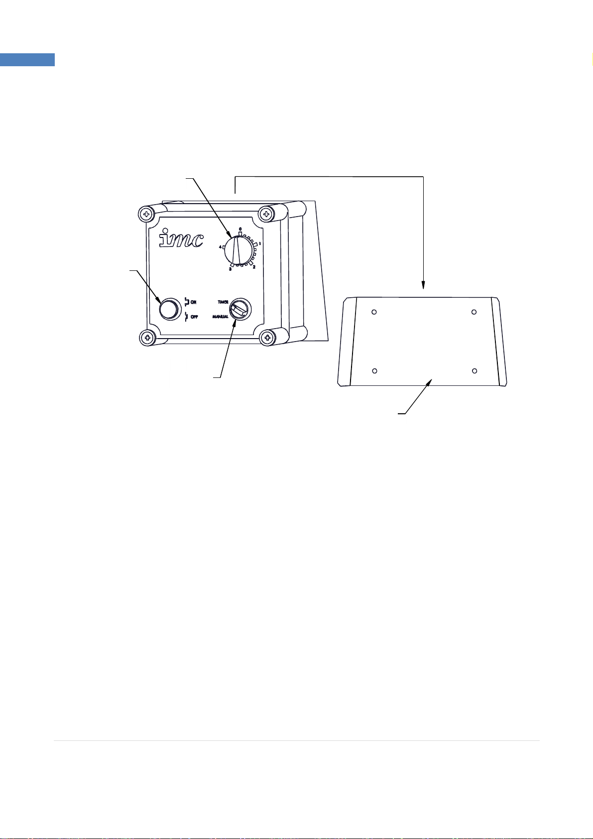
CONTROLS
The peeler has a separate box for mounting on a wall bracket near the machine.
TIMER
ON/OFF
BUTTON
TIMER / MANUAL
SELECTOR SWITCH
WALL BRACKET
Note: Control boxes for three phase machines have separate on and off buttons
INSTALLATION
For the Installer:
· These instructions contain important information designed to help the user obtain the
maximum benefit from the investment in an IMC SP Peeler.
· Please read them carefully before starting work, and consult with the supplier in the event of
any queries.
· Be sure to leave this instruction manual with the user after the installation of the machine is
complete.
Procedure:
The SP Range is supplied with a pedestal and is designed to be bolted to the floor. The control box is
designed to be mounted on a wall bracket so that it is easily accessible once the machine is installed.
Place the machine in its desired location and mark through the pedestal base the location of the five
floor fixing holes. Remove the machine and prepare the floor for rawl bolts or other suitable floor
fixings. Replace the unit into working position and fit the rawl bolts or other fixings. Tighten up the
fixings.
6 | P a g e

SP-RANGE
Place the control box bracket in the desired location and mark through the four screw holes. Remove
the bracket and prepare the wall for rawl plugs or other suitable wall fixings. Secure the bracket in
place with four screws. Slide the control box onto its wall bracket.
WATER SUPPLY
Connect the water supply pipe to the water inlet located on the top of the lid, and secure using the
supplied hose clips. Fit the other end of the supply pipe to a cold water supply that incorporates a tap
or shut off valve that can be used to regulate the water flow to approximately 3 – 4 litres per minute.
The water inlet is fitted with a baffle to improve the distribution of water into the cylinder. This may
cause minor splashing on the surface of the lid; if this becomes severe, reduce water flow as required.
The maximum water pressure for the supply is 10 bar. Ensure that the hose supplied with the machine
is used and that an old hose is not reused.
PLEASE NOTE: These machines are fitted with an air-break to prevent back syphonage into the mains
supply. Some local authorities may nevertheless require connection is made to a storage cistern rather
than direct to the mains supply.
This applies to UK installations only. Overseas customers should install the machine in accordance with
local regulations.
If in doubt, check with your local authority.
WASTE OUTLET CONNECTION
The peeler has two possible waste outlet locations. If it is required to change the waste outlet location,
remove both the existing waste outlet and the blanking plate on the opposite side. Refit both the waste
outlet and the blanking plate in their new positions.
A flexible hose, supplied with the machine, can be fitted over the waste outlet to direct the waste into
a gully or intercepting tank. If required, secure with the hose clip supplied. Longer lengths of flexible
hose are available from IMC on request.
The waste outlet also incorporates a 2” BSP female thread for connection to standard 54mm (2”) waste
pipe. DO NOT reduce the diameter of the waste pipe to below 54mm. The length of the pipe should
be kept to a minimum and the pipe must have a fall of at least 1:15. Changes of direction should be
made by swept bends rather than elbows and cleaning eyes should be fitted where possible in
accordance with standard plumbing practice.
A trap is not necessary if the discharge is into a gully or an intercepting tank, although a trap must be
provided in the outlet pipe from the intercepting tank. If a trap is required, it should be made with 45°
bends and not with a ‘U’ or ‘P’ bend or with a bottle trap.
7 | P a g e
 Loading...