

IMC Eagle 2 SUN CONTROL, SOLR-2ELC-15, SOLR-2ELC-10, SOLR-2EHW-20, SOLR-2EHW-30 Service And Installation Instructions
INSTRUMENTS, INC.INSTRUMENTS, INC.
468 Liberty Drive
Wittenberg, WI 54499
USA
TEL 715- 253-2801 Ver. 10-05-2007
FAX 715- 253-2811
www.imcinstruments.com
EAGLE 2
EAGLE 2
DIFFERENTIAL TEMPERATURECONTROLLER
DIFFERENTIAL TEMPERATURECONTROLLER
SERVICE AND INSTALLATION INSTRUCTIONS
IMC LCD MASTER DIGITAL DISPLAY PANEL
IMC LCD MASTER DIGITAL DISPLAY PANEL
for REMOTE indication
for
REMOTE indication
MAIN FEATURES
- Microprocessor
dependability with ambient
operation from -10 to 120 F
- Large easy to read 40 character
display
showing every parameter measured and controlled
by the microprocessor.
- Plugin adapter REMOTE DISPLAY
indicator for distances up to 150 feet with a CAT-5 cable.
- Fault LED indicators
- PC Serial DATA port with built in transmitter
foot long cable for ease in remote startup and diagnostics.
Full industrial isolation is available for safe PC interface.
- Long-term diagnostics
software that is included with Windows OS.
- Fast and easy
and easy access for all other wiring.
- Electrostatic
- True one HP
- Polyester coated 16 gage
accuracy and
°
(20x2) back light LCD
for IMC’s monitor and
for quick servicing and diagnostics.
for up to 500
and PC data logging using “Terminal”
installation with screw-less sensor terminals
discharge protected.
Hi-Reliability relay operation.
rugged steel enclosure.
Product # SOLR-2ELC-10 (pictured)
SUN CONTROL
SUN CONTROL
- Industrial Rated 400 °F(204°C) 10 K thermistors
- Two additional auxiliary Thermistor inputs
- Selectable Overrides low temperature Shut down Freeze protection SAFE
for or modes for operation.
with +/- 1 °F accuracy.
which can be located up to 1000’ away.
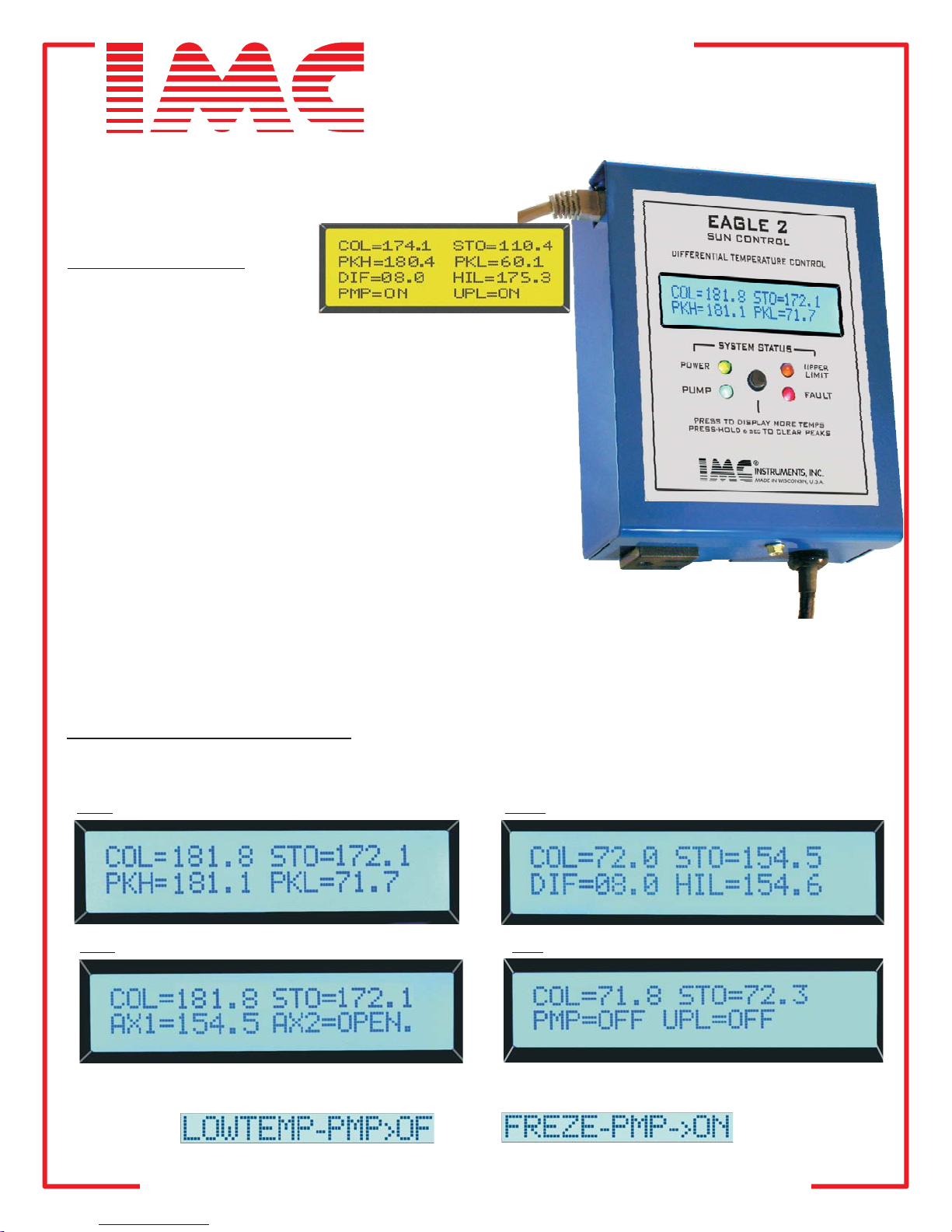
OPERATION- LCD DISPLAY
The LCD display has 2 lines of 20 characters each. The first line permanently displays the COLLECTOR and
the STORAGE temperatures. The second line can be paged by pressing the button located just below the
LCD display. The following 4 pages display all system information including OVERRIDE messages.
PG 1 PG 2
PG 3 PG4
SYSTEM OVERRIDE MESSAGES FLASH on the LOWER LCD LINE as follows:
INSTRUMENTATION WITH QUALITY ENGINEERINGINSTRUMENTATION WITH QUALITY ENGINEERING

INSTRUMENTS, INC.INSTRUMENTS, INC.
OPERATION-CONTROLLER
TEMPERATURE DIFFERENCE CONTROL-
collector and the sensor in the storage tank exceeds the “temperature difference” dialed in the controller, the PUMP
relay will actuate after a 30 second delay. The BLUE LED indicator will also turn on. If the temperature difference
decreases and falls below 4 F (2.2 C), the PUMP relay and the BLUE LED indicator will turn off with out delay.
°°
When the temperature difference between the sensor in the solar
HIGH LIMIT CONTROL
- If the temperature in the storage tank exceeds the HI-LIMIT dialed setting, the PUMP
relay will be turned OFF without delay regardless of the status of the “temperature difference” that exists between
the STORAGE tank and the solar COLLECTOR. The BLUE LED indicator will also turn be turned OFF. Should the
storage tank temperature fall 4 degrees below the setting in the HI-LIMT, the controller will then resume normal
operation. The PUMP relay will always have a 30 second delay before actuation into the ON position and the BLUE
LED will always show its STATUS condition.
LOW TEMPERATURE SHUT DOWN OVERRIDE-
This feature is available to prevent the system from operating at
low outdoor temperatures. If this feature is enabled normal operation will stop when the COLLECTOR temperature
falls below 50 degrees F. The
the COLLECTOR temperature returns to 70 degrees or above. To enable this feature,
onto the jumper pins marked “LO’ on the circuit board.
FREEZE PROTECTION OVERRIDE-
freezing when the outdoor temperature drops too low.
PUMP relay will then be turned off. Normal control operation will not resume until
a jumper must be placed
Only ONE of these two override features can be enabled.
This feature is available to prevent a non-drain back “water ” system from
only
If this feature is enabled normal operation will stop when the
COLLECTOR temperature falls below 37 degrees F. The PUMP relay will then be turned on until the COLLECTOR
temperature reaches 52 degrees. Normal control operation will resume above this temperature. To enable this
feature, a jumper must be placed onto the jumper pins marked “FZ’ on the circuit board. Only ONE of these two
override features can be enabled.
DATA PORT-
Requires an IMC-Data port/RS232 ADAPTER. This will allow interface to a standard PC serial port.
The ADAPTER can further accept a serial/USB converter to connect directly to PC or Laptops that only have USB
ports. If wireless operation is desired for short distances, BLUE TOOTH transceiver can also be connected. The
rate at which the data is sent from the EAGLE solar controller is determined by a jumper in the controller as show in
the CONTROLLER diagram. If the jumper is placed in position labeled “2S”, one complete line of “Total system
information” to the PC every 2 seconds which is necessary when performing diagnostics or a system startup. If the
same jumper is placed in position labeled ”6M’, then DATA will be sent every 6 minutes. This will allow a more
suitable data-send rate for long term DATA LOGGING, specially when storing the data in a “CAPTURE” file set up in
the PC “Terminal” communications program such as “Hyper Terminal” or “Terminal”.
SAMPLE DATA PORT PRINT
RUNTIME COLL-T STOR-T DIFF-T HILI-T AUX-1 AUX-2 PUMP UPLim FAULT
0:09 125.9 73.7 08.0 110.0 212.2 205.4 ON OFF S
0:09 25.9 73.7 08.0 110.0 212.2 205.4 OFF OFF LO-TMP->OFF
0:10 25.9 73.7 08.0 110.0 212.8 205.4 ON OFF PmpSW!
0:00 OPEN.S 73.9 08.0 110.0 212.8 205.4 OFF OFF SENS!, PmpSW! O
0:00 -16.0 74.7 08.0 110.0 25.9 184.6 ON OFF FREZE-PMP->ON
0:00 74.9 08.0 110.0 25.9 154.6 OFF OFF
0:09 125.9 173.7 08.0 173.0 112.2 95.4 OFF ON Storage reached UPPER LIMIT
An can also be connected to the DATA PORT. It has an RJ-45
SHRT.S
IMC LCD MASTER DIGITAL DISPLAY PANEL
ystem collecting solar HEAT
System in LO TEMP shut down PUMP->OFF
Pump switch ON
pen sensor, pump switch OFF
System in Freeze protect mode
Shorted sensor->System OFF
PUMP->ON
jack and is supplied with a 3 foot long cable that can be substituted with a standard CAT5 cable with a maximum
length of 150 feet and are available at most retail stores. The display panel also has a A PEAK RESET button
located on the side to reset previous STORAGE temperature peaks.
LCD MASTER DISPLAY PANEL
Information displayed is as follows:
Pg1 COLLECTOR TEMPERATURE
STORAGE TEMPERATURE
DIFFERENTIAL CONTROL SETTING
HI LIMIT CONTROL SETTING
PUMP STATUS
UPPER LIMIT STATUS
PEAK HI= MAXIMUM TEMPERATURE
PEAK LO= MINIMUM TEMPERATURE
AUXILIARY SENSORS 1 AND 2
INSTRUMENTATION WITH QUALITY ENGINEERINGINSTRUMENTATION WITH QUALITY ENGINEERING
 Loading...