

IMC EAGLE 2 SOLR-2ELC-10 Service And Parts Manual Supplement
INSTRUMENTATION WITH QUALITY ENGINEERING
INSTRUMENTS, INC.
INSTRUMENTS, INC.
COL=174.1 STO= 1 10 . 4
PKH =18 0.4 PKL= 6 0 . 1
DI F=0 8 . 0 H IL= 17 5 . 3
PMP= O N UPL=ON
SUN CONTROL
468 Liberty Drive
Wittenberg, WI 54499
®
U.S.A.
Te l: 715- 253-2801 Ver.11-01-2008
Fax: 715- 253-2811
Web: www.solar.imcinstruments.com
SERVICE AND INSTALLATION INSTRUCTIONS
MAIN FEATURES
- Microprocessor accuracy and
dependability with ambient
operation from -10 to 120 F
- Large easy-to-read 40 character (20x2) backlit LCD
display showing every parameter measured and
Controlled by the microprocessor.
- PC DATA PORT with built-in transmitter allows optional
adapter and up to 500 ft. cable to interface with computers
for ease in startup and remote diagnostics. Or, for adding
an Optional large 80 character (4x20) backlit LCD display.
Remote-mount up to 150 ft. distances with a CAT-5 cable.
- Long-term diagnostics and data logging is possible using
communications software that is included in Windows’ OS.
- Fault LED indicators for quick servicing and diagnostics
- Features for fast installation and wiring
- Electrostatic discharge protected
- One HP or 20 AMP high reliability relay
- Polyester coated 16 gage rugged steel enclosure
- Model available with receptacle & power cord or with 1/2”
conduit holes for higher current permanent wiring
°
DIFFERENTIAL TEMPERATURE CONTROLLER
EAGLE 2
SUN CONTROL
P# SOLR-2ELC-10
COL=174.1 STO= 1 10 . 4
PKH =18 0.4 PKL= 6 0 . 1
DI F=0 8 . 0 H IL= 17 5 . 3
PMP= O N UPL=ON
IMC’S LCD MASTER DIGITAL DISPLAY PANEL
FOR REMOTE INDICATION
- Two industrial 400°F (204°C) rated 10 K thermistors with +/- 1°F accuracy are included.
- Two auxiliary thermistor inputs for optional sensors that can be located up to 1000’ away.
- Selectable overrides for low temperature shut down or freeze protection modes for safe operation.
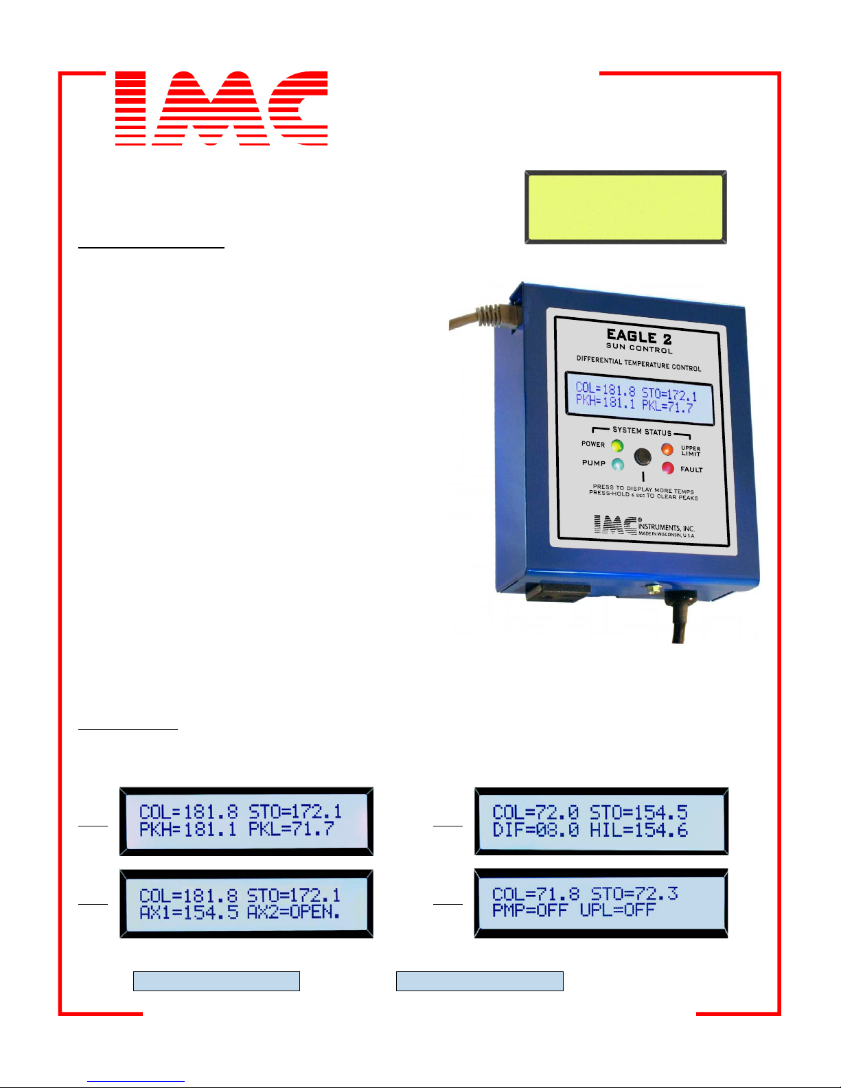
LCD DISPLAY
The LCD display has 2 lines of 20 characters each. The first line permanently displays the COLLECTOR and the
STORAGE temperatures. The second line can be paged by pressing the button located just below the LCD
display. The following 4 pages display all system information including OVERRIDE messages.
PG 2PG 1
PG 4PG 3
SYSTEM OVERRIDE MESSAGES on the LOWER LCD LINE as follows:FLASH
LOWTEMP-PMP>OF
FREZE-PMP->ON
INSTRUMENTATION WITH QUALITY ENGINEERING
INSTRUMENTATION WITH QUALITY ENGINEERING
INSTRUMENTS, INC.
INSTRUMENTS, INC.
COL=174.1 STO= 1 10 . 4
PKH =18 0.4 PKL= 6 0 . 1
AX1=-10.5 AX2= 17 5 . 3
PMP= O N UPL=ON
COL=174.1 STO= 1 10 . 4
PKH =18 0.4 PKL= 6 0 . 1
DI F=0 8 . 0 H IL= 17 5 . 3
PMP= O N UPL=ON
®
DATA-PORT
Requires an IMC Data-Port ADAPTER that will allow interface to a standard computer’s serial RS232 port. The
ADAPTER can also accept a serial to USB converter to connect directly to portable computers that only have
USB ports. If wireless operation is desired for short distances, BLUE TOOTH transceiver can also be
connected. The rate at which the data is sent from the EAGLE solar controller is determined by a jumper in the
controller as show in the CONTROLLER diagram on page 4. If the jumper is placed on position labeled “2S”,
one complete line of “total system information” will be sent to the computer every 2 seconds which is necessary
when performing diagnostics or a system startup. If the same jumper is placed on position labeled ”6M”, then
data will be sent every 6 minutes. This will allow a more suitable data-send rate for long-term DATA LOGGING,
specially when storing the data in a “CAPTURE” file setup in the computer’s communications program such as
“Terminal” or “Hyper Terminal”.
SAMPLE DATA PORT PRINT
RUNTIME COLL-T STOR-T DIFF-T HILI-T AUX-1 AUX-2 PUMP UPLim FAULT
0:00 125.9 73.7 08.0 110.0 212.2 205.4 ON OFF System collecting solar HEAT
0:06 25.9 73.7 08.0 110.0 212.2 205.4 OFF OFF LO-TMP->OFF System in LO TEMP shut down PUMP->OFF
0:12 25.9 73.7 08.0 110.0 212.8 205.4 ON OFF PmpSW! Pump switch ON
0:18 OPEN.S 73.9 08.0 110.0 212.8 205.4 OFF OFF SENS!, PmpSW! Open sensor, pump switch OFF
0:24 -16.0 74.7 08.0 110.0 25.9 184.6 ON OFF FREZE-PMP->ON System in Freeze protect mode PUMP->ON
0:30 SHRT.S 74.9 08.0 110.0 25.9 154.6 OFF OFF Shorted sensor->System OFF
0:36 125.9 173.7 08.0 173.0 112.2 95.4 OFF ON Storage reached UPPER LIMIT
An IMC LCD MASTER DIGITAL DISPLAY PANEL can also be connected to the DATA PORT. It has an RJ-45
jack and is supplied with a 3 foot long cable that can be substituted with a standard CAT5 cable up to150 feet long.
These ethernet cables are available at most retail stores. The display panel also has a PEAK RESET button
located on the side to reset previous STORAGE temperature peaks.
The Information on the LCD MASTER DISPLAY PANEL is displayed as follows:
COLLECTOR TEMPERATURE
STORAGE TEMPERATURE
DIFFERENTIAL CONTROL SETTING
HI LIMIT CONTROL SETTING
PUMP STATUS
UPPER LIMIT STATUS
PEAK HI= MAXIMUM TEMPERATURE
PEAK LO= MINIMUM TEMPERATURE
AUXILIARY SENSORS 1 AND 2
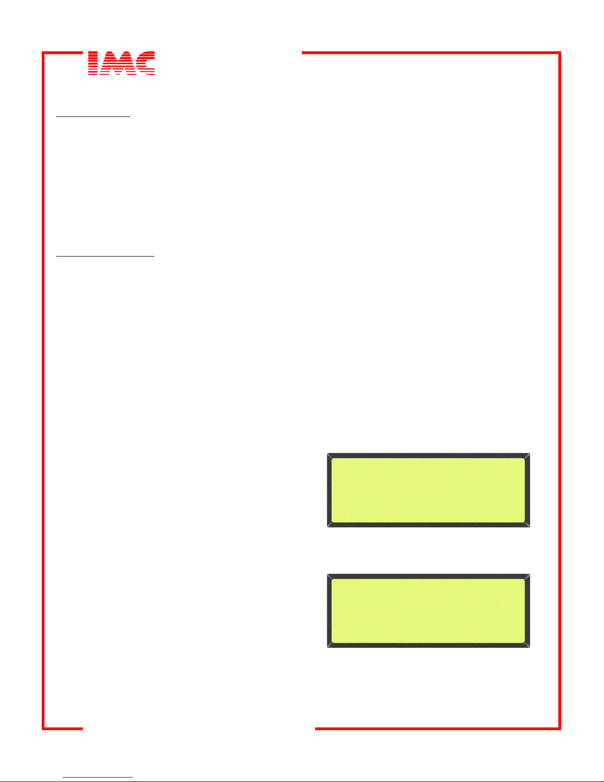
PAGE 1
COL=174.1 STO= 1 10 . 4
PKH =18 0.4 PKL= 6 0 . 1
DI F=0 8 . 0 H IL= 17 5 . 3
PMP= O N UPL=ON
This Master LCD has a second page that will
display the auxiliary sensor temperatures.
To display, press and release the PAGE/RESET
button on the side of the display housing.
The auxiliary sensors will be displayed within 2
seconds. To RESET the STORED PEAK
temperatures of the storage tank, press and hold
for 6 seconds the PAGE/RESET button. The
current temperatures will appear after the button
is released. The Master LCD display is updated
every 2 seconds.
PAGE 2
COL=174.1 STO= 1 10 . 4
PKH =18 0.4 PKL= 6 0 . 1
AX1=-10.5 AX2= 17 5 . 3
PMP= O N UPL=ON
INSTRUMENTATION WITH QUALITY ENGINEERING

INSTRUMENTATION WITH QUALITY ENGINEERING
INSTRUMENTS, INC.
INSTRUMENTS, INC.
®
IMPORTANT NOTICE
These EAGLE Series Temperature Controls are intended to control equipment under normal operating
conditions. Where failure or malfunction of EAGLE Series Control could lead to an abnormal operating condition
that could cause personal injury or damage to the equipment or other property, other devices (limit or safety
controls) or systems (alarm or supervisory) intended to warn of or protect against failure or malfunction of the
EAGLE Series Control must be incorporated into and maintained as part of the control system.
CONTROLLER OPERATION
TEMPERATURE DIFFERENCE CONTROL- When the temperature difference between the sensor on the
solar collector and the sensor in the storage tank exceeds the dialed temperature difference setting (ON DIF),
the PUMP relay will actuate after a 30 second delay. The BLUE LED indicator will also turn ON. When the
temperature difference decreases and falls below 4 F (2.2 C), the PUMP relay and the BLUE LED indicator will
turn off without delay.
HIGH LIMIT CONTROL- When the temperature in the storage tank exceeds the HI-LIMIT dialed setting, the
PUMP relay will be turned OFF without delay regardless of the status of the temperature difference that exists
between the STORAGE tank and the solar COLLECTOR. The BLUE LED indicator will also turn OFF. When
the storage tank temperature falls 4 degrees below the setting in the HI-LIMT, the controller will then resume
normal operation. The PUMP relay will always have a 30 second delay before switching ON and the BLUE LED
will always show its STATUS condition.
°°
LOW TEMPERATURE SHUT-DOWN OVERRIDE- This feature is available to prevent the system from
operating at low outdoor temperatures. If this feature is enabled, normal operation will stop when the
COLLECTOR temperature falls below 50 F. The PUMP relay will then be turned OFF. Normal control
operation will not resume until the COLLECTOR temperature returns to 70 F or above. To enable this feature,
a jumper must be placed onto the jumper pins marked “LO’ on the circuit board. Only ONE of these two
override features can be enabled.
FREEZE PROTECTION OVERRIDE- This feature is available to prevent a non-drain back “water only” system
from freezing when the outdoor temperature drops too low. If this feature is enabled normal operation will stop
when the COLLECTOR temperature falls below 37 F. The PUMP relay will then be turned ON until the
COLLECTOR temperature reaches 52 F. Normal control operation will resume above this temperature. To
enable this feature, a jumper must be placed onto the jumper pins marked “FZ’ on the circuit board. Only ONE
of these two override features can be enabled.
STATUS INDICATION LEDS- There are four status indication LEDS. The GREEN LED indicates that the
microprocessor is POWERED and the SOLAR controller is running. The BLUE LED indicates PUMP operation.
When ON, the PUMP is operating and solar energy is being stored in the STORAGE tank. The AMBER LED
indicates if the UPPER LIMIT temperature in the storage has been exceeded. The RED LED indicates when
there is a fault condition. The conditions that can cause the fault LED to turn ON are as follows: OPEN or
SHORTED or OUT of RANGE temperature SENSORS, pump RELAY SWITCH NOT set to “AUT” (automatic)
position and internal component malfunctions. The RED LED will always be FLASHING when the FAULT
indication is ON
SENSORS- Industrial 400°F (204°C) rated 10K IMC thermistors have +/- 1°F accuracy. When installed, they
will not exceed ONE degree of additional error for cable distances up to 1000 feet of 18ga., 700 feet of 20ga. or
500 feet of 22ga.
SENSOR SCREW TERMINALS- There are 9 screws on a GREEN block located at the top edge of the board.
These terminals accept solid or stranded wire from 18ga. to 22ga. They are NEC class 2 circuit connections.
°
°
°
°
POWER AND RELAY TERMINALS- The power terminals are for 120 vac operation (230 vac operation is
optional). Use solid wire in 16 or 18 ga. and stranded (19 max) in 12 or 14 ga. The power RELAY is rated for 20
Amps and is designed to connect directly to PUMPS or FANS not exceeding a total of 1 hp. A 30 amp.
(resistive load) board option is available. Current and voltage ratings will vary for models with cords and
receptacles. See model label for specific ratings.
INSTRUMENTATION WITH QUALITY ENGINEERING
 Loading...