

Imation Nexsan E60, Nexsan E60V, Nexsan E48V, Nexsan E48VT, Nexsan E60VT Installation Manual
...Page 1

NEXSAN E-SERIES™
Installation Guide
For the Nexsan E60™/E60V™/E60VT™
and Nexsan E48™/E48V™/E48VT™
RAID Storage Units
Document Number NXS-ES4U-IG
Revision 01
NEXSAN 1445 Lawrence Drive, T housand Oaks, CA 91320 | p. 866.4.NEXSAN | www.nexsan.com
Page 2

Copyright © 2010–2014 by Imation. All Rights Reserved Worldwide. www.imation.com
Trademarks
Nexsan®, Nexsan NST6000™, Nexsan NST6000MC™, Nexsan NST5000™, Nexsan NST5100™, Nexsan NST5110™, Nexsan NST5100X™,
Nexsan NST5120™, Nexsan NST5130™, Nexsan NST5300™, Nexsan NST5310™, Nexsan NST5320™, Nexsan NST5330™, Nexsan
NST5500™, Nexsan NST5510™, Nexsan NST5520™, Nexsan NST5530™, Nexsan E-Centre™, Nexsan NST224X™, Nexsan E60™, Nexsan
E60V™, Nexsan E60VT™, Nexsan E60X™, Nexsan E60XV™ Nexsan E48™, Nexsan E48V™, Nexsan E48VT™, Nexsan E48X™, Nexsan
E48XV™, Nexsan E32V™, Nexsan E18™, Nexsan E18V™, Nexsan E18X™, Nexsasn E18XV™, Nexsan FASTier™, and the Nexsan logo
are trademarks or registered trademarks of Imation.
All other trademarks and registered trademarks are the property of their respective owners.
Patents
This product is protected by one or more of the following patents, and other pending patent applications worldwide:
United States patents US8,191,841, US8,120,922
United Kingdom patents GB2296798B, GB2297636B, GB2466535B, GB2467622B, GB2467404B
Regulatory compliance
United States Statement for FCC: This equipment has been tested and found to comply with the limits for a Class A digital device, pursuant to
Part 15 of the FCC Rules. These limits are designed to provide reasonable protection against harmful interference when the equipment is
operated in a commercial environment. This equipment generates, uses, and can radiate radio frequency energy and, if not installed and used in
accordance with the instruction manual, may cause harmful interference to radio communications. Operation of this equipment in a residential
area is likely to cause harmful interference in which case the user will be required to correct the interference at his own expense.
Electromagnetic Emissions: FCC Class A, EN 55022 Class A, EN 61000-3-2/-3-3, CISPR 22 Class A
Electromagnetic Immunity: EN 55024/CISPR 24, (EN 61000-4-2, EN 61000-4-3, EN 61000-4-4, EN 61000-4-5, EN 61000-4-6, EN 61000-4-8,
EN 61000-4-11)
Safety: CSA/EN/IEC/UL 60950-1 Compliant, UL or CSA Listed (USA and Canada), CE Marking (Europe)
California Best Management Practices Regulations for Perchlorate Materials: This Perchlorate warning applies only to products containing CR
(Manganese Dioxide) Lithium coin cells. Perchlorate Material-special handling may apply. See
www.dtsc.ca.gov/hazardouswaste/perchlorate.
About this document
Unauthorized use, duplication, or modification of this document in whole or in part without the written consent of Imation is strictly prohibited.
Imation reserves the right to make changes to this manual, as well as the equipment and software descri bed in this manual, at any time without
notice. This manual may contain links to web sites that were current at the time of publication, but have since been moved or become inactive. It
may also contain links to sites owned and operated by third parties. Imation is not responsible for the content of any such third-party site.
Page 3

Contents
About this manual v
Audience v
Conventions v
Text v
Notes, tips, cautions, and warnings v
Contacting Nexsan vi
Contacting service and support vi
Related documents vi
Safety notices viii
Revision history ix
NXS-ES4U-IG Rev. 01, February 2014: ix
Old format: ix
Version 3.4, October 2013: ix
Version 3.3, March 2013: ix
Version 3.2, October 2012: ix
Version 3.1, July 2012: ix
Version 3.0, May 2012: ix
Version 2.9, March 2012: ix
Version 2.8, February 2012: ix
Version 2.7, December 2011: x
Version 2.6, August 2011: x
Version 2.5, June 2011: x
Version 2.4, April, 2011: x
Version 2.3, March, 2011: x
Version 1.12, March, 2011: x
Version 1.11, January, 2011: x
Version 1.10, January, 2011: x
Version 1.9, December, 2010: xi
Chapter 1: Overview 1
Front panel 2
Field-replaceable modules 2
Other modules 2
LEDs 2
Other items 3
Rear panel 4
Field-replaceable modules 5
Other modules 5
Connectors 5
LEDs 6
Switches 7
Turbo cards (VT units only) 7
Host port options 7
Drawer interior 9
Field-replaceable modules 9
Other modules 9
Nexsan E60™/Nexsan E48™
Installation Guide
Nexsan by Imation
www.nexsan.com
iii
Page 4

LEDs 9
Physical characteristics 10
Dimensions, Nexsan E60™/E60V™/E60VT™ 10
Dimensions, Nexsan E48™/E48V™/E48VT™ 10
Power 10
Cooling 11
Materials 11
Environment 11
Chapter 2: Getting Started 13
Taking delivery of the Nexsan E60™/Nexsan E48™ 14
Unpack the Nexsan E60™/Nexsan E48™ 14
Before installation 17
Required tools and equipment 17
Prepare the site 17
Prepare the unit 18
Chapter 3: Installing the Nexsan E60™Nexsan E48™ 21
Prepare the mounting rails 22
Mount the Nexsan E60™/Nexsan E48™ 26
Restore the rear modules 28
PSUs 28
RAID Controllers 28
Load the disk drives 29
Attach communication cables 31
Power on the Nexsan E60™/Nexsan E48™ 32
Set up the system 33
Glossary 35
iv Nexsan by Imation
www.nexsan.com
Nexsan E60™/Nexsan E48™
Installation Guide
Page 5
About this manual
About this manual
This installation guide provides information and steps for performing the physical installation of the Nexsan
E60™ and Nexsan E48™ disk storage chassis and their V and VTvariants.
Audience
This guide has been prepared for the following audience:
IT system administrators
Engineers
Technicians
Conventions
Text
Internal cross-references, hyperlinks, URLs, and email addresses are displayed in underlined blue.
Cross-references to other documents, system messages, and non-interactive items in the graphical user
interface (GUI) are displayed in italic.
Text that refers to labels on the physical unit or interactive items in the graphical user interface (GUI) is in
boldface.
Notes, tips, cautions, and warnings
Note Notes contain important information, present alternative procedures, or call attention to certain items.
Tip Tips contain handy information for end-users, such as other ways to perform an action.
CAUTION: In hardware manuals, cautions alert the user to items or situations which may cause
damage to the unit or result in mild injury to the user, or both. In software manuals, cautions alerts the
user to situations which may cause data corruption or data loss.
WARNING: Warnings alert the user to items or situations which may result in severe injury
or death to the user.
Nexsan E60™/Nexsan E48™
Installation Guide
Nexsan by Imation
www.nexsan.com
v
Page 6
About this manual
Contacting Nexsan
Founded in 1999 and headquartered in Thousand Oaks, California, Nexsan provides a comprehensive range
of enterprise-class, easy-to-use and efficient system solutions that offer customers the ultimate value
proposition when it comes to meeting their ever-evolving storage requirements. Our hardware and software
products uniquely combine the benefits of cost-effective performance, power and space efficiency, density,
ease of use, outstanding scalability and unmatched reliability to provide Highly Efficient Storage (HES)
performance and functionality.
Worldwide Headquarters
Imation Nexsan Solutions
1445 Lawrence Drive,
Thousand Oaks, CA 91320
Telephone 866.463.9726
805.418.2700 Outside of North America
Technical Services 866.263.9726
760.690.1111 Outside of North America
Fax 805.418.2799
E-mail nexsansupport@imation.com
Contacting service and support
Imation's Nexsan Technical Services Group provides worldwide assistance with installation, configuration,
software support, warranty and repair for all Nexsan products. A variety of service and support programs are
available to provide you with the level of coverage and availability your operation requires.
US and Canada
By phone 866.263.9726
760.690.1111
E-mail nexsansupport@imation.com
Europe, Middle East, Africa
By phone +44 (0) 1332 291600
E-mail nexsansupport@imation.com
Japan
E-mail nexsansupport@imation.com
Global Support Request By Web
By Internet http://nexsan.com/support/service-request.aspx
Related documents
The following Nexsan product manuals contain related information:
vi Nexsan by Imation
www.nexsan.com
Nexsan E60™/Nexsan E48™
Installation Guide
Page 7

About this manual
Nexsan E-Series™ FRU Removal and Replacement Guide for the Nexsan
E60™/E60V™/E60VT™/Nexsan E48™/E48V™/E48VT™ RAIDStorage Units
Nexsan E-Series™ Installation Guide for the Nexsan E60X™/E60XV™/Nexsan E48X/™E48XV™
RAIDStorage Expansion Units
Nexsan E-Series™ FRU Removal and Replacement Guide for the Nexsan E60X™/E60XV™/Nexsan
E48X/™E48XV™ RAIDStorage Expansion Units
Nexsan RAIDStorage User Guide
Nexsan E-Series™ Snapshots and Replication User Manual
Nexsan E60™/Nexsan E48™
Installation Guide
Nexsan by Imation
www.nexsan.com
vii
Page 8
Safety notices
Safety notices
This guide covers the Nexsan E60™/E60V™/E60VT™ and Nexsan E48™/E48V™/E48VT™ digital storage
units only. Refer to the relevant product manuals for information on other Nexsan E-Series™ storage or
expansion units and other Nexsan products mentioned in this guide.
Always observe the following precautions to reduce the risk of injury and equipment damage:
WARNING: There is a risk of ELECTRIC SHOCK if Nexsan E-Series™ components are removed
or tampered with when unit power is on. Only a Trained Operator may remove certain fieldreplaceable units (FRUs). The Nexsan E-Series™ storage units include the following FRUs:
Power Supply modules
Controller modules
Disk drives
Fan modules
Computer components and disk drives are sensitive to static discharge. Take precautions to discharge
any electrostatic charge from your person before and while handling components with your hands or any
tools. Use an anti-static wrist-strap.
Ensure correct lifting methods are used when removing the unit from its packaging and positioning it into its
required location. When lifting the system, two people at either end should lift slowly with their feet spread
out to distribute the weight. Always keep your back straight and lift with your legs.
When removing the unit from the packaging, DO NOT lift the unit by any plastic parts or module handles on
the chassis. Doing so may cause damage to the chassis or to internal components, or both. Lift the unit
ONLY by the bottom edges of the chassis, using safe lifting practices.
The unit should only be installed in a clean, dry environment. The operating temperature is 10º to 35º C (50º
to 95º F), with operating relative humidity at 20 to 95%, non-condensing.
Do not install the unit in an enclosed cabinet or other small area without ventilation.
When installing the unit as a rack-mounted component, ensure that all Nexsan-supplied mounting fixtures
are secure. All bolts and screws should be fully tightened. Failure to comply with this may result in the unit
not being fully supported in the rack and could lead to the product falling from the rack, causing personal
injury or damage to other rack components.
Ensure that the rack is sufficiently stable by having wall anchors and/or stabilizing legs, and that the floor
supporting the rack has sufficient strength for the overall weight loading.
The cordset specification for the Nexsan E60™/E60V™/E60VT™ and Nexsan E48™/E48V™/E48VT™ in
North America is USA IEC C13 to IEC C14, rated 250V/10A. When applying power to the unit, use ONLY
the IEC power cords originally supplied with it. Do NOT use other power cords, even if they appear
identical to the supplied cords.
Only a fully-trained Service Engineer is authorized to disassemble any other part of the unit, and then only
when the unit is powered off.
All Nexsan E-Series™ storage units have multiple power connections; as a result, you must remove all
power leads to completely remove power from the unit.
Nexsan E-Series™ storage units do not have power switches. Do NOT attach the power cords until the
unit is fully installed, with all disk drives in place.
viii Nexsan by Imation
www.nexsan.com
Nexsan E60™/Nexsan E48™
Installation Guide
Page 9

Revision history
Revision history
This section lists updates and new material added to the Nexsan E-Series™Installation Guide for the Nexsan
E60™/E60V™/E60VT™ and Nexsan E48™/E48V™/E48VT™ RAIDStorage Units.
NXS-ES4U-IG Rev. 01, February 2014:
Changed formatting throughout to reflect Nexsan as an Imation brand; separated installation content from
FRUreplacement content into two documents; changed name of document to Nexsan E-Series™ Installation
Guide for the Nexsan E60™/E60V™/E60VT™ and Nexsan E48™/E48V™/E48VT™ RAIDStorage Units.
Old format:
Version 3.4, October 2013:
Changed name of document to Nexsan E60/E60V/E60VT and Nexsan E48/E48V/E48VT Installation and
Maintenance Manual; updated references to Nexsan E60™ and Nexsan E48™ throughout document to
include V and VT variants, where applicable; added introductory paragraphs to Chapter 1, Overview on page
1; added illustration of Nexsan E60VT™/Nexsan E48VT™ rear panel to Rear Panel on page 3; updated
information for expansion controllers on page 4; added section describing VT turbo card LEDs to page 5;
removed references to side rail latches from page 24, page 25, page 32, page 33, page 34, page 36, page 37,
page 38, and page 39.
Version 3.3, March 2013:
Updated references to Nexsan RAID Storage User Manual; updated dimensions and power specifications on
page 8; updated Attach Communication Cables on page 26 and Power Up the Unit on page 26 to reflect new
procedures in the Nexsan E60X/E48X Installation and Maintenance Manual.
Version 3.2, October 2012:
Updated cordset specification on page vii, page 4, page 7, page 12, and page 26; updated rail kit information in
tables on page 7; updated the accessory box packing list on page 10; updated required tools and equipment on
page 12; updated rack mounting instructions starting on page 15; added note regarding batteries to page 26.
Version 3.1, July 2012:
Added patent information to page ii and back cover; updated Common Terms and Abbreviations on page 45.
Version 3.0, May 2012:
Updated illustrations on page 1 and page 3 to call out drawer, PSU, and controller numbers; changed Nexsan
E48™ power specification on page 4, page 7, and page 12; added instructions for attaching two expansion
units to a Nexsan E60™/Nexsan E48™ to Attach Communication Cables on page 25.
Version 2.9, March 2012:
Added cordset specification to page vii, page 4, page 7, page 12, and page 26; changed power specification
on page 4, page 7, and page 12; added illustration of expansion unit connectors to Attach Communication
Cables on page 25.
Version 2.8, February 2012:
Added information for Nexsan E48™.
Nexsan E60™/Nexsan E48™
Installation Guide
Nexsan by Imation
www.nexsan.com
ix
Page 10

Revision history
Version 2.7, December 2011:
Changed name of document from Hardware Manual to Installation and Maintenance Manual; updated
photographs throughout to reflect new front panel; added description of new SAS-to-Host option to Host Port
Options on page 4; added section Unpack the Nexsan E60™ to Chapter 2, page 7.
Version 2.6, August 2011:
Added caution regarding unit weight to page viii; added caution regarding power outlet to page viii and page 10;
added legends to front panel, back panel, and drawer interior photos in Chapter 1; reorganized section
Switches on page 4; removed reference to allen wrench and note regarding rack mounts from page 7; added
section Required Tools and Equipment on page 10; bullet paragraph on page 12 changed to Note; added
photographs to Mount the Nexsan E60™ on page 15 and page 16; added photographs to Load the Disk Drives
on page 18 and page 19; expanded section Attach Communication Cables on page 21; expanded section
Power Up the Nexsan E60 on page 22; added caution to page 23 and page 24; added photographs to Disk
Drives on page 26 and page 27.
Version 2.5, June 2011:
Added description of new 10Gb iSCSI option to page 4; updated references throughout.
Version 2.4, April, 2011:
Complete reorganization of Hardware Manual contents.
Version 2.3, March, 2011:
Images replaced on pages 19 and 24.
Version 1.12, March, 2011:
Updated manual to new style throughout; name of product changed from Nexsan B60 to Nexsan E60™;
warning regarding unpacking the unit added under For Your Own Safety, page 5; warning regarding unpacking
the unit added under Taking Delivery, page 7; note regarding installing multiple units added under Before You
Begin, page 8; note regarding installing multiple units added under Loading Disk Drives, page 16; deleted
section Expansion Wiring Configurations, page 17; removed instructions for powering up the unit when an
expansion unit is present from Power-up, page 17; added information about powered-down unit to Front LEDs,
page 18; note regarding installing multiple units added under Disk Insertion, page 23.
Version 1.11, January, 2011:
Inserted reference to expansion units under For Your Own Safety, page 5; inserted statement regarding
expansion units under Cabling, page 16; inserted section Expansion Wiring Configurations, page 17; added
instructions for powering up the unit when an expansion unit is present under Power-up, page 18; changed
reference to SAS ports under SAS Expansion Port LED’s, page 20.
Version 1.10, January, 2011:
Clarified instructions for securing the front mounts under Mounting the Front Bracket, page 11; added caption
to illustration under Securing the Chassis, page 15; deleted reference to expansion unit under Cabling, page
16; deleted reference to expansion unit under Power-Up, page 17; changed reference to SAS ports under SAS
Port LED’s, page 19; clarified number of usable iSCSI ports under iSCSI Port LED’s, page 20.
x Nexsan by Imation
www.nexsan.com
Nexsan E60™/Nexsan E48™
Installation Guide
Page 11

Revision history
Version 1.9, December, 2010:
Name of product changed from NXS-B60 to Nexsan B60; expanded safety information under For Your Own
Safety, page 5; updated specifications under Nexsan B60 Technical Specifications, page 6; Getting Started
section expanded on page 7; removed example from Circuit Overloading on page 8; expanded and clarified
rack mounting instructions under Installing the Nexsan B60 into a Rack on pages 8–15; Disk Drives section
removed from page 16; Disk Drawer (internal) LEDs section added to page 18; expanded and clarified
descriptions under Rear LEDs on pages 19–20; Disk Drives and Fan Replacement sections added under
Physical Components on pages 21–24.
Nexsan E60™/Nexsan E48™
Installation Guide
Nexsan by Imation
www.nexsan.com
xi
Page 12

Revision history
xii Nexsan by Imation
www.nexsan.com
Nexsan E60™/Nexsan E48™
Installation Guide
Page 13

Chapter 1:Overview
The Nexsan E60™/E60V™/E60VT™ and Nexsan E48™/E48V™/E48VT™ units are 4U, rack-mountable
RAID storage systems which can hold up to 48 or 60 SATA, SAS, or SSD data disks.
The base models of the Nexsan E60™ and Nexsan E48™ use 3Gb/s SAS for internal communication
between the RAID Controllers and hard disks. The V and VT variants use 6Gb/s SAS for internal
communication. The VT variants also have a turbo card installed in each RAID Controller which optimizes
sequential writes in parity-based RAIDs. There is no upgrade path between the base models and either the V
or VT variants.
Aside from the difference in internal communication speed and the presence of the turbo card in the VT units,
there is no operational difference between the base models and the V and VT variants.
Note Unless otherwise specified, “Nexsan E60™/Nexsan E48™” is assumed to refer to all variants (base
model, V, and VT) of the Nexsan E60™ and Nexsan E48™ storage systems. Where information applies to
only one variant, that variant is specified.
This chapter contains the following sections:
Chapter
1
Front panel 2
Rear panel 4
Drawer interior 9
Physical characteristics 10
Nexsan E60™/Nexsan E48™
Installation Guide
Nexsan by Imation
www.nexsan.com
1
Page 14
1
2a
3 4 5
6
7
LEDs:
3. Power
4. Disk
5. Environment
6. Status
Modules:
1. Drawer Front Assembly
2a. Active Drive Drawer 0
2b. Active Drive Drawer 1
2c. Active Drive Drawer 2
Other:
7. Drawer Lock
2b
2c
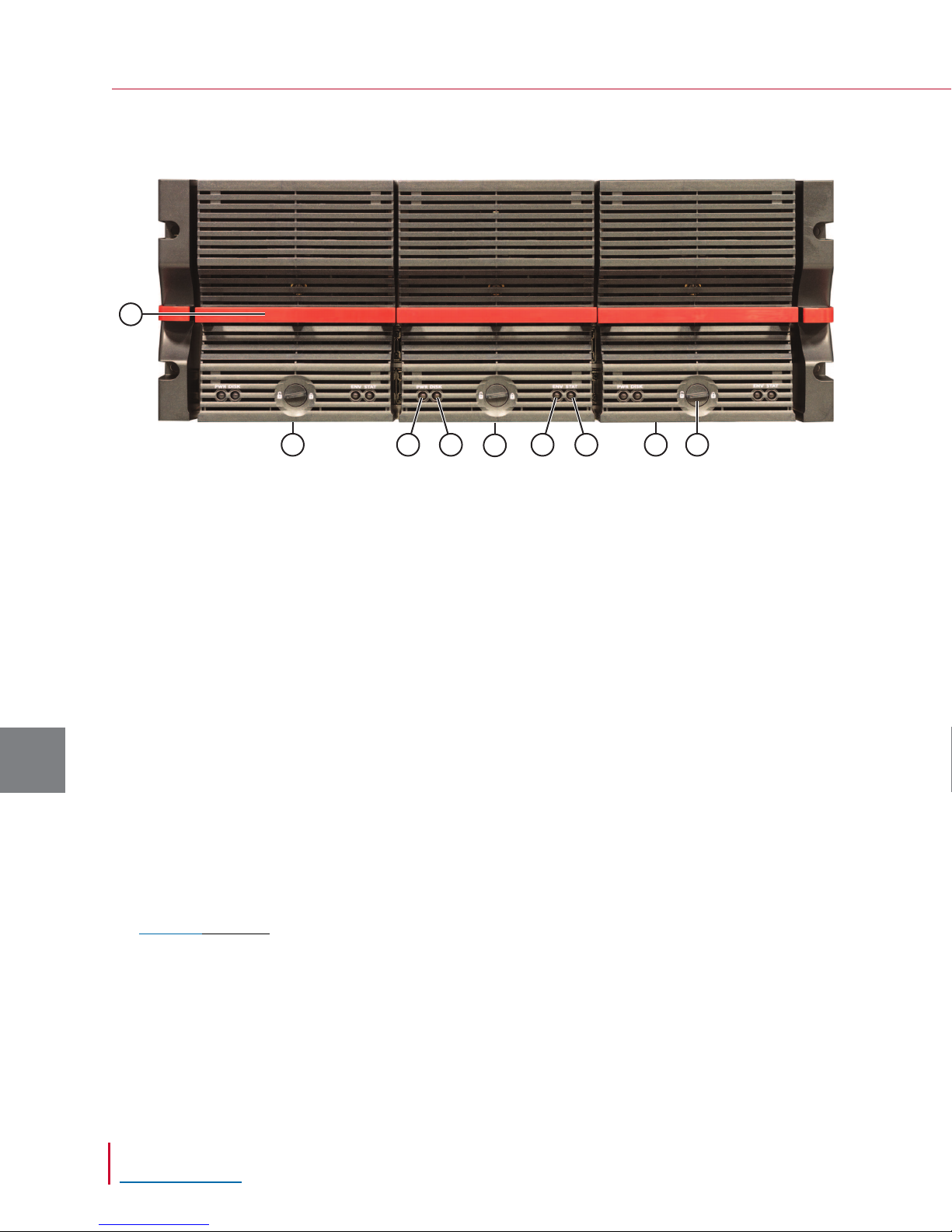
Front panel
Front panel
Figure 1-1: Nexsan E60™/Nexsan E48™ front panel
Field-replaceable modules
1. Drawer Front Assembly w/ Fan: Each assembly can be field-replaced in the event of a fan failure by
removing a screw on each side of the drive drawer (see the Nexsan E-Series FRURemoval and
Replacement Guide for your unit).
Other modules
2. Active Drive Drawers (3): Each drawer can hold up to 16 (for Nexsan E48™ units) or 20 (for Nexsan
E60™ units) 3.5" disk drives, for a total of up to 48 or 60 drives in the unit. Can only be replaced by a fully
trained Service Engineer.
1
LEDs
3. Power LED(PWR): Indicates the status of power to the components in the drawer. Green indicates that
all power levels are within specifications. Red indicates that one or more power levels are outside of
specifications. The Environmental Information page (under System Information) in the graphical user
interface (GUI) displays details (see the Nexsan RAID Storage User Guide).
If the PWR LED on the left drive drawer is amber and all other front panel LEDs are off, this means that
the unit has been powered down through the GUI. It can be powered back up using the SW0 switch (see
Switches on page 7).
4. Disk LED (DSK): Indicates the status of the disk drives in the drawer. Green indicates that all disk drives
are operating within specifications. Red indicates that one or more disk faults have been detected. The
Disk Drives page (under RAID Information) in the graphical user interface (GUI) displays details (see the
Nexsan RAID Storage User Guide).
2 Nexsan by Imation
www.nexsan.com
Nexsan E60™/Nexsan E48™
Installation Guide
Page 15

Chapter 1: Overview
5. Environment LED (ENV): Indicates the temperature and fan status for the drawer. Green indicates that
the drawer temperature is within specifications and that all fans are operating properly. Red indicates that
the temperature exceeds specifications or that one or more fans are not operating properly. The
Environmental Information page (under System Information) in the graphical user interface (GUI)
displays details (see the Nexsan RAID Storage User Guide).
6. Status LED (STAT): Indicates overall status. Green indicates that the unit is operating within
specification. Amber indicates that the drawer is unlocked. Red indicates a fault in the unit, which could
be any of the following:
A Power Supply Unit issue with the fan, temperature, or voltage
A RAID Controller issue with the temperature, voltage, battery, firmware, or other hardware
A drawer voltage issue
The Environmental Information page (under System Information) in the graphical user interface (GUI)
displays details (see the Nexsan RAID Storage User Manual).
Other items
7. Drawer Lock: Secures the drive drawer in place. When this lock is disengaged, the STAT LED turns
amber.
Nexsan E60™/Nexsan E48™
Installation Guide
Nexsan by Imation
www.nexsan.com
1
3
Page 16
1a 1b
2a 2b
33 3
5
6
4
7
8
13
14
10
11
15
16
Field Replaceable Modules:
1a. RAID Controller 0
1b. RAID Controller 1
2a. Power Supply Unit (PSU) 0
2b. Power Supply Unit (PSU) 1
Other Modules:
3. Interconnect Service Modules (ISMs)
Connectors:
4. Power
5. Expansion
6. Management
7. Serial
8. iSCSI
9. Host Port
LEDs:
10. PSU status
11. PSU Fan status
12. Expansion Port status
13. Mgmt Port status/activity
14. Controller status
15. iSCSI status/activity
Switches:
16. SW0
9
12
Rear panel
Rear panel
Figure 1-2: Nexsan E60™/Nexsan E60V™ and Nexsan E48™/Nexsan E48V™ rear panel (Fibre Channel
connections shown)
1
4 Nexsan by Imation
www.nexsan.com
Nexsan E60™/Nexsan E48™
Installation Guide
Page 17

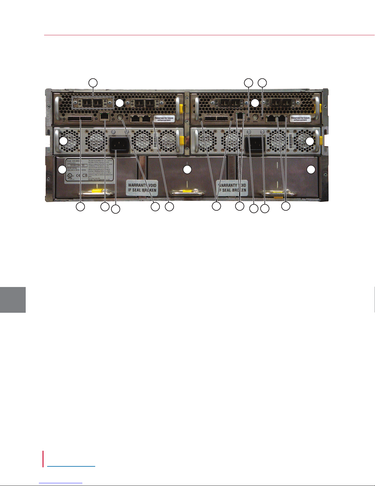
1a 1b
2a 2b
33 3
4
5 6
7
8
11
12
13
14
15
16
Field Replaceable Modules:
1a. RAID Controller 0
1b. RAID Controller 1
2a. Power Supply Unit (PSU) 0
2b. Power Supply Unit (PSU) 1
Other Modules:
3. Interconnect Service Modules (ISMs)
Connectors:
4. Expansion
5. Management
6. Power
7. Serial
8. iSCSI
9. Host Port (see Figure 1.3)
LEDs:
10. Expansion Port status
11. Mgmt Port status/activity
12. Controller status
13. PSU status
14. PSU Fan status
15. iSCSI status/activity
Switches:
16. SW0
Other:
17. Turbo Card
9
10
17
Chapter 1: Overview
Figure 1-3: Nexsan E60VT™/Nexsan E48VT™ rear panel (Fibre Channel connections shown)
Field-replaceable modules
1. RAID Controller(s) (1 or 2). Each unit can be field-replaced in the event of failure (see the Nexsan E-
Series FRURemoval and Replacement Guide for the Nexsan E60™/E60V™/E60VT™ and Nexsan
E48™/E48V™/E48VT™ RAIDStorage Units). RAID Controllers are designated Controller 0 (left) and
Controller 1 (right) in the graphical user interface (GUI) (see the Nexsan RAID Storage User Guide).
Note In single-controller units, the right slot contains a back plate which helps regulate air flow.
2. Power Supply Units (PSUs) (2). Each unit can be field-replaced in the event of a PSU or PSU fan failure
(see the Nexsan E-Series FRURemoval and Replacement Guide for the Nexsan
E60™/E60V™/E60VT™ and Nexsan E48™/E48V™/E48VT™ RAIDStorage Units).
Other modules
3. Interconnect Service Modules (ISMs) (3). Can only be replaced by a fully-trained Service Engineer.
Connectors
4. Power (2): 200–240VAC, 47–63Hz (for Nexsan E60™ units) or 110–240VAC, 47–63Hz (for Nexsan
E48™ units).
CAUTION: The cordset specification for the Nexsan E60™/Nexsan E48™ in North America is
IEC C13 to IEC C14 rated 250V/10A. When applying power to the system, use ONLY the IEC
power cords originally supplied with the unit. Do NOT use other power cords, even if they
appear identical to the supplied cords.
1
Nexsan E60™/Nexsan E48™
Installation Guide
Nexsan by Imation
www.nexsan.com
5
Page 18

Rear panel
5. Two expansion ports (EXP 0 and EXP 1) per RAID Controller: Mini-SAS 26 pin I-Pass (8088) expansion
connectors, each with four 6Gb/s SAS links.
6. One Management port (MGMT) per RAID Controller: Ethernet 10/100 dedicated management port (RJ45)
for web-based configuration.
7. One SERIAL port per RAID Controller: Mini-DIN serial port for low-level reporting (Support use only).
8. Four iSCSI ports (0 through 3) per RAID Controller: 1Gb/s Ethernet ports (RJ45s) for iSCSI. If a host port
option is installed (see Host port options on the facing page), only ports 0 and 1 are usable.
9. Host ports: See Host port options on the facing page.
LEDs
10. PSU status LED: Indicates the status of power. Green indicates that the 12V and 3V3 outputs are within
specification. Red indicates that one or the other, or both, are outside of specified limits. Orange
indicates that the PSU is in standby mode. The Environmental Information page (under System
Information) in the graphical user interface (GUI) has more information. See the Nexsan RAIDStorage
User Guide.
11. PSU fan LED: Indicates the status of the PSU fans. Green indicates that all fans are operating within
specifications. Red indicates that one or more fans are either running too slowly or have failed. When the
PSU is in standby mode, this LED is off. The Environmental Information page (under System
Information) in the graphical user interface (GUI) has more information. See the Nexsan RAIDStorage
User Guide.
1
12. Expansion port LEDs (L0 and L1): Indicate the connection status for each expansion port. Green
indicates that the SAS cable is properly connected. Flashing amber indicates that the cable is improperly
connected. If no cable is connected, this LED is off.
13. Management port LEDs (activity and speed): The left LED flashes green when there is port activity. The
right LED lights up green when there is a 100Mb/s connection. When there is only a 10Mb/s connection,
the right LED is off.
14. Controller status LED (STAT): Indicates the status of the RAID Controller:
Solid blue indicates that the controller is operating within specifications and that there is no user data
in the cache.
Solid green indicates that the controller is operating within specifications and that there is user data in
the cache, which will be retained in flash memory upon power-down and then restored when the unit is
powered up again.
Flashing red (once per second) indicates that the controller is offline due to a fault being detected.
Flashing green (twice per second) indicates that the controller is operating in battery-backup mode
and is backing up cached data to flash memory. This can take several minutes.
Alternating blue and red indicates that the controller is booting in Emergency mode (see Switches on
the facing page).
15. iSCSI port LEDs (activity and status): For 1Gb/s and 100Mb/s connections, the left LED illuminates
green, and both LEDs flash green when there is activity. For 10Mb/s connections, the left LED remains
off, and the right LED flashes green where there is activity.
6 Nexsan by Imation
www.nexsan.com
Nexsan E60™/Nexsan E48™
Installation Guide
Page 19

1
2 2
Fibre Channel 10Gb Ethernet, Opitcal 10Gb Ethernet, Copper
SAS-to-Host
1 1
1
2 2
Chapter 1: Overview
Switches
16. SW0 Switch: This switch can be used to turn the RAID Controller off or on, boot the controller in
Emergency mode, or silence an audible alarm.
With the unit powered on:
Briefly press the SW0 switch to silence the audible alarm. This can also be done via the graphical
user interface (GUI) (see the Nexsan RAID Storage User Guide).
Press and hold the SW0 switch for approximately 8 seconds to power down the RAID Controllers. If
there is data in the cache, it will be stored in flash memory. This is the same as performing a System
Shutdown via the graphical user interface (GUI) (see the Nexsan RAID Storage User Guide). On dual-
controller systems, both SW0 switches must be held simultaneously for 8 seconds.
With the unit powered off:
Press and hold the SW0 switch on either RAID Controller for approximately 4 seconds to power up
the unit. Release the SW0 switch to boot normally.
Continue pressing the SW0 switch after the unit powers up to put the RAID Controllers into
Emergency mode (see the Nexsan RAID Storage User Guide). Emergency mode is indicated by the
controller status LED alternating between blue and red (see LEDs on the previous page).
Turbo cards (VT units only)
17. Turbo card LEDs: The LEDs on the turbo card indicate the status of the card. The LEDs are:
SP: Currently unused.
PAR: Indicates the status of the parity engine. Green indicates that the parity engine is active. If the
parity engine is inactive, this LED is off.
MEM: Indicates the status of the turbo card’s cache memory. Green indicates that data is in the
cache that needs to be written to disk. If there is no data in the cache, this LED is off.
STAT: Indicates the status of the turbo card. Green indicates that the card is operating normally.
Orange indicates that the card is initializing its cache memory. Red indicates a fault in the turbo card.
If the turbo card has been deactivated, this LED is off.
Host port options
Figure 1-4: Host port options
The RAID Controllers can be configured (with one or two optional Host Bus Adapter (HBA) cards) for one of
three different host port options: Fibre Channel, 10Gb/s iSCSI (10GbE), or SAS-to-Host.
Note Because of the presence of the turbo card (see Turbo cards (VT units only) above), Nexsan E60VT™
and Nexsan E48VT™ units can only have one HBA card installed.
1
Nexsan E60™/Nexsan E48™
Installation Guide
Nexsan by Imation
www.nexsan.com
7
Page 20

Rear panel
1. Depending on the RAID Controller configuration, the host port connectors are one of the following:
Two Fibre Channel ports (0 and 1) per RAID Controller: 8Gb/s Fibre Channel optical SFPs.
Two 10Gb iSCSI (10GbE) ports (0 and 1) per Controller: 10Gb/s Ethernet optical SFPs or copper SFP
sockets for iSCSI.
Two SAS ports (0 and 1) per Controller: Mini-SAS 26 pin I-Pass (8088) connectors, each with four
6GB/s SAS links.
2. Depending on the RAID Controller configuration, the host port LEDs are one of the following:
Fibre Channel port LEDs (speed and activity): The upper LED is orange when there is a 2Gb/s
connection and green when there is a 4Gb/s connection. The lower LED flashes yellow for data
activity, but also lights up yellow when there is an 8Gb/s connection. When there is an 8Gb/s
connection, the upper LED is off. During the power-up sequence, both Fibre Channel port LEDs are
solid yellow. If both LEDs are flashing yellow, the Fibre Channel connection has been lost.
Note For Nexsan E60™/E60V™ and Nexsan E48™/E48V™ units with two HBA cards, the right
HBAcard's LEDs are inverted.
10Gb iSCSI port LEDs (connection and activity): For each 10Gb iSCSI connection (left and right), the
lower LED lights up green when there is a 10GbE connection and the upper LED flashes green when
there is activity. When there is no connection, these LEDs are off.
Note For Nexsan E60™/E60V™ and Nexsan E48™/E48V™ units with two HBA cards, the right
HBAcard's LEDs are inverted.
1
Note The SAS-to-Host port option has no LEDs.
8 Nexsan by Imation
www.nexsan.com
Nexsan E60™/Nexsan E48™
Installation Guide
Page 21

Drawer interior
1
2
3
4
1. Disk Drives
2. Rear Fan Assembly
3. Drive Rails
4. Drive Status LEDs
1
2
3
4
1. Disk Drives
2. Rear Fan Assembly
3. Drive Rails
4. Drive Status LEDs
Chapter 1: Overview
Figure 1-5: Nexsan E60™ drawer interior
Figure 1-6: Nexsan E48™ drawer interior
Field-replaceable modules
1. Disk Drives: Up to 16 (for Nexsan E48™ units) or 20 (for Nexsan E60™ units) 3.5" disk drives in each
drawer. Disk drives can be field-replaced in the event of failure (see the Nexsan E-Series FRURemoval
and Replacement Guide for the Nexsan E60™/E60V™/E60VT™ and Nexsan E48™/E48V™/E48VT™
RAIDStorage Units).
2. Rear Fan Assembly: Dual-fan assembly located at the rear of each drawer. Can be field-replaced in the
event of failure (see the Nexsan E-Series FRURemoval and Replacement Guide for the Nexsan
E60™/E60V™/E60VT™ and Nexsan E48™/E48V™/E48VT™ RAIDStorage Units).
1
Other modules
3. Drive Guides: Align with plastic rails on disk drives to guide installation. These are integral to the drive
drawer and cannot be individually replaced.
LEDs
4. Drive status: One for each disk drive slot. Solid green indicates that the disk is operating within
specifications and is not currently being accessed. Flashing green indicates disk activity. Red indicates
that a disk fault has been detected and that the disk is not currently being used by the system. For disk
drive slots where no disk drive is installed, this LED is off.
Nexsan E60™/Nexsan E48™
Installation Guide
Nexsan by Imation
www.nexsan.com
9
Page 22

Physical characteristics
Physical characteristics
Dimensions, Nexsan E60™/E60V™/E60VT™
Measurement Value
Chassis height 4U: 177mm (6.97")
Chassis length 950mm (37.4")
1
Chassis length, including
fascia and handles
Chassis width, body 448mm (17.64")
Chassis width, overall 482.6mm (19")
Unit weight, no drives 48 kg (106 lbs.)
Unit weight, with drives 93 kg (205 lbs.)
Rack mount kit length 660mm to 914mm (26" to 36")
Rack mount kit weight approx. 2.5 kg (5.5 lbs.)
1,026mm (40.39")
(allow at least 150mm for cables at rear; a 1,200mm rack is recommended)
Dimensions, Nexsan E48™/E48V™/E48VT™
Measurement Value
Chassis height 4U: 177mm (6.97")
Chassis length 835mm (32.87")
Chassis length, including
fascia and handles
Chassis width, body 448mm (17.64")
887mm (35.95")
(allow at least 150mm for cables at rear; a 1,200mm rack is recommended)
Chassis width, overall 482.6mm (19")
Unit weight, no drives 47.63 kg (105 lbs.)
Unit weight, with drives 84 kg (185.2 lbs.)
Rack mount kit length 660mm to 914mm (26" to 36")
Rack mount kit weight approx. 2.5 kg (5.5 lbs.)
Power
Two 1,600W load-sharing, hot-pluggable, redundant PSUs.
Nexsan E60™/E60V™/E60VT™ nominal input voltage is 200–240VAC, 47–63Hz. Cordset specification
in North America is IEC C13 to IEC C14 rated 250V/10A.
10 Nexsan by Imation
www.nexsan.com
Nexsan E60™/Nexsan E48™
Installation Guide
Page 23

Chapter 1: Overview
Nexsan E48™/E48V™/E48VT™ nominal input voltage is 110–240VAC, 47–63Hz. Cordset specification
in North America is IEC C13 to IEC C14 rated 250V/10A.
Typical power consumption for the E60 units is 1,164W (5.18A) for 600GB SAS drives and 806W (3.6A) for
3TB SATA drives. Peak current is up to 15A.
Typical power consumption for the E48 units is 1,059W (4.74A) for 600GB SAS drives and 684W (3.0A) for
3TB SATA drives. Peak current is up to 15A.
Cooling
Front panel: One 120mm 12V axial fan (life 40,000 hrs) per drive drawer, for a total of three.
Internal: Two double-gang 12V axial fans (life 40,000 hrs) per drive drawer, for a total of six.
PSUs: Four 12V axial fans (life 40,000 hrs) per PSU, for a total of eight.
Materials
Chassis, external: Extruded aluminium and galvanized sheet steel, top and bottom
Chassis, internal: Aluminium supports, steel divider plates, and steel sub-assemblies
Fascia: ABS (blend) Thermoplastic UL 94 V.0
Environment
Ambient operating temperature: 5°C–35°C (41°F–95°F)
Minimum drawer operation temperature: 10°C (50°F)
1
Nexsan E60™/Nexsan E48™
Installation Guide
Nexsan by Imation
www.nexsan.com
11
Page 24

Chapter 1: Overview
12 Nexsan by Imation
www.nexsan.com
Nexsan E60™/Nexsan E48™
Installation Guide
Page 25

Chapter 2:Getting Started
This docuemt is designed to enable the user to install and configure the Nexsan E60™/Nexsan E48™
RAIDstorage unit quickly and safely. Please read this document carefully and review all of the information in
this section before installing the unit.
This chapter contains the following sections:
Taking delivery of the Nexsan E60™/Nexsan E48™ 14
Before installation 17
Chapter
2
Nexsan E60™/Nexsan E48™
Installation Guide
Nexsan by Imation
www.nexsan.com
13
Page 26

Taking delivery of the Nexsan E60™/Nexsan E48™
Taking delivery of the Nexsan E60™/Nexsan E48™
Upon receipt of your Nexsan E60™/Nexsan E48™, inspect the packaging for damage that may have been
sustained in transit. If there is visible damage on the packaging, contact your shipper before proceeding.
Unpack the Nexsan E60™/Nexsan E48™
Carefully unpack your Nexsan E60™/Nexsan E48™ and inspect each item before installation.
► To unpack the Nexsan E-Series™ unit:
1. Carefully cut the straps holding the box closed and remove the outer lid.
Figure 2-1: Opening the outer box
2
2. Remove the accessory boxes and disk boxes from the outer packaging.
Figure 2-2: Removing the accessory and disk boxes
14 Nexsan by Imation
www.nexsan.com
Nexsan E60™/Nexsan E48™
Installation Guide
Page 27

Chapter 2: Getting Started
3. Open the accessory box and make sure that all expected contents are present.
Figure 2-3: Accessory box contents (example)
The accessory box should contain:
rack mounting hardware:
two (2) rail assemblies, one left and one right
eight (8) rail nuts
eight (8) large bolts for securing the rail nuts to the rack
two (2) chassis rack-mount “ears”, one left and one right
four (4) screws for attaching the chassis “ears” to the Nexsan E60™/Nexsan E48™ unit
four (4) brackets, four (4) nuts, and four (4) bolts for securing the Nexsan E60™/Nexsan E48™ to the
rack
two (2) power cables
disposable ESD strap
serial cable
any additional items that may have been ordered, such as SAS cables or Fibre Channel cables
4. Open the disk boxes and make sure that the proper number of disk drives is included.
Figure 2-4: Disk box contents (example)
2
Nexsan E60™/Nexsan E48™
Installation Guide
Nexsan by Imation
www.nexsan.com
15
Page 28

Taking delivery of the Nexsan E60™/Nexsan E48™
5. Remove the outer packaging sleeve and the foam lid covering the Nexsan E60™/Nexsan E48™ unit.
Figure 2-5: Removing the outer packaging sleeve and foam lid
6. With the help of a second person, carefully lift the Nexsan E60™/Nexsan E48™ unit out of the
packaging.
Figure 2-6: Removing the unit from the box
2
Tip The packaging that the Nexsan E60™/Nexsan E48™ ships in is reusable and should be retained for
future re-shipment. Be sure to keep all packaging components.
16 Nexsan by Imation
www.nexsan.com
CAUTION: When removing the unit from the packaging, DO NOT lift the unit by any plastic parts or
module handles on the chassis. Doing so may cause damage to the chassis or to internal components, or both. Lift the unit ONLY by the bottom edges of the chassis, using safe lifting practices.
Nexsan E60™/Nexsan E48™
Installation Guide
Page 29

Chapter 2: Getting Started
Before installation
Required tools and equipment
To perform the installation, you will need the following tools and equipment:
a suitable equipment rack (1,200mm deep recommended, see Physical characteristics on page 10) with
sufficient load capacity to hold the unit’s weight.
a size P1 Phillips-head screwdriver
enough CAT 6 Ethernet cable to connect the unit to the local area network (LAN)
enough CAT 6 Ethernet cable, fibre-optic cable, twisted-pair copper cable, or SAS cable to connect the unit
to the storage area network (SAN) (see Attach communication cables on page 31)
Prepare the site
Before installing the unit, prepare the installation site and rack.
CAUTION: Always fully stabilize racks with wall anchors or stabilizing legs, or both, before mounting the unit or any other components on the rack.
CAUTION: Ensure that the floor beneath the mounting rack has enough load-bearing capacity to support the rack and all mounted components.
CAUTION: Ensure that the A/C power socket/outlet is near the equipment and easily accessible.
► To prepare the site and rack for unit installation:
Ensure that the ambient temperature at the installation site is between 5°C (41°F) and 35°C (95°F). If the
temperature at the site is not actively regulated, ensure that daily and seasonal temperature changes will
not result in the ambient temperature going outside these limits.
Situate the rack so that full air flow at both the front and the rear of the unit is possible.
Ensure that the rack is properly grounded per the manufacturer’s instructions and that proper ESD
safeguards are in place.
Ensure that the power drawn by the unit or units does not overload the available electrical supply (see
Power on page 10). The Nexsan E60™ is designed to run from a nominal 200–240V supply due to its high
peak power loading, and the Nexsan E48™ is designed to run from a nominal 110–240V supply. Cordset
specification for the Nexsan E18 in North America is IEC C13 to IEC C14 rated 250V/10A.
2
Nexsan E60™/Nexsan E48™
Installation Guide
Nexsan by Imation
www.nexsan.com
17
Page 30

Before installation
Prepare the unit
Before installation, prepare the unit.
CAUTION: Before opening any of the drive drawers on the Nexsan E60™/Nexsan E48™, be sure
that the internal temperature is 10°C (50°F) or above. If the unit has been shipped or stored in very
low temperatures, allow the unit to come to room temperature. Failure to do so may result in internal
cable damage.
CAUTION: Computer components and disk drives are sensitive to electrostatic discharge (ESD).
Be sure to ground any electrostatic charge from your person before touching components with your
hands or with any tools. While installing the unit, use the anti-static wrist strap shipped with the Nexsan E60™/Nexsan E48™.
► To prepare the unit for installation:
1. Remove the two PSUs and the one or two RAID Controllers from the unit:
Note For single-Controller units, you can leave the back plate in place.
a. RAID Controller: Press the spring lock tab away from the edge of the Controller, then carefully
remove the Controller from the unit. Support the weight of the Controller with your free hand while
removing it.
Figure 2-7: Removing the RAID Controller
2
b. PSU: Press the spring lock tab away from the edge of the PSU, then carefully remove the PSU from
Set the PSUs and RAID Controller(s) aside.
18 Nexsan by Imation
www.nexsan.com
Tip For dual-Controller units, it may be helpful to label the Controllers “left” and “right” so that you
remember to replace them into the same slots from which they were removed.
the unit. Support the weight of the PSU with your free hand while removing it.
Figure 2-8: Removing the PSU
Nexsan E60™/Nexsan E48™
Installation Guide
Page 31

2. Attach the chassis rack-mount “ears” to the front of the unit.
a. Extend the left and right drive drawers slightly.
Figure 2-9: Extending drive drawers
b. Line up the rack-mount “ears” to the drawer rails.
Figure 2-10: Lining up the “ears”
Chapter 2: Getting Started
c. Attach the ears to the sides of the unit using the supplied screws.
Figure 2-11: Attaching the chassis rack-mount “ears”
d. Close and lock the drawers again when the ears are attached.
Note If you are installing more than one Nexsan E60™/Nexsan E48™ unit, keep each unit’s disk drives with
the unit they shipped with so as to avoid installing them into the wrong unit (disks are preconfigured for the
specific unit at the factory).
Nexsan E60™/Nexsan E48™
Installation Guide
Nexsan by Imation
www.nexsan.com
2
19
Page 32

Chapter 2: Getting Started
20 Nexsan by Imation
www.nexsan.com
Nexsan E60™/Nexsan E48™
Installation Guide
Page 33

Chapter
Chapter 3:Installing the Nexsan E60™Nexsan E48™
The Nexsan E60™ and Nexsan E48™ come in single-Controller and dual-Controller configurations. These
instructions assume a dual-Controller unit installation, but where the steps differ, additional instructions for
single-Controller units are provided.
This chapter contains the following sections:
Prepare the mounting rails 22
Mount the Nexsan E60™/Nexsan E48™ 26
Restore the rear modules 28
Load the disk drives 29
Attach communication cables 31
Power on the Nexsan E60™/Nexsan E48™ 32
Set up the system 33
3
Nexsan E60™/Nexsan E48™
Installation Guide
Nexsan by Imation
www.nexsan.com
21
Page 34

Prepare the mounting rails
Prepare the mounting rails
CAUTION: Ensure that your rack can support the total weight of all mounted components and that
your floor is sufficiently strong. Since the unit is a fixed-in-rack design, rear cable management arms
are not required.
The rails are labeled “L” (left) and “R” (right) on the outside surfaces, as shown in Figure Figure 3-1. When
installing them into the rack, be sure to place them on the correct sides.
Figure 3-1: Mounting rails’ “left” and “right” labeling
3
► To prepare the mounting rails for unit installation:
1. Extend the slides to fit your rack.
Note The rails can be adjusted to between 26" (66cm) and 36" (91.4cm).
Figure 3-2: Extending the rack-mount rails
22 Nexsan by Imation
www.nexsan.com
Nexsan E60™/Nexsan E48™
Installation Guide
Page 35

Chapter 3: Installing the Nexsan E60™Nexsan E48™
2. Attach the rack nuts to the front of the rack on the left and right sides. The rack nuts should be mounted
towards the interior of the rack.
Note The rack nuts should be placed 3U apart. Use the rail as a guide for rack nut placement.
Figure 3-3: Attaching the front rack nuts
3. Attach the rack nuts to the rear of the rack on the left and right sides. The rack nuts should be mounted
towards the interior of the rack.
Figure 3-4: Attaching the rear rack nuts
Nexsan E60™/Nexsan E48™
Installation Guide
Nexsan by Imation
www.nexsan.com
3
23
Page 36

Prepare the mounting rails
4. (For square-hole racks only) For each of the four plastic brackets:
a. Insert the bracket nut into the recess in the plastic bracket.
Figure 3-5: Inserting the nut into the plastic bracket
b. Clip the bracket to the appropriate place on the front of the mounting rail.
Figure 3-6: Clipping the plastic bracket to the front of the rail
3
24 Nexsan by Imation
www.nexsan.com
Figure 3-7: Rails fronts with all four brackets attached
Nexsan E60™/Nexsan E48™
Installation Guide
Page 37

Chapter 3: Installing the Nexsan E60™Nexsan E48™
5. Attach the rear slide of the left rail to the rack nuts by sliding the large part of the mounting hole over the
rack nut and then pressing outward to seat the nut in the small part of the mounting hole.
Figure 3-8: Attaching the mounting rail in back
6. Repeat the previous step for the front of the mounting rail.
Figure 3-9: Attaching the mounting rail in front
7. Repeat the previous two steps for the right mounting rail.
The mounting rails are now ready to receive the unit.
Figure 3-10: Both mounting rails in place
Note The rails may seem “loose” before the unit is mounted on them. This is normal. Once the unit is on the
rails, they are held in place by the body of the unit.
Nexsan E60™/Nexsan E48™
Installation Guide
Nexsan by Imation
www.nexsan.com
3
25
Page 38

Mount the Nexsan E60™/Nexsan E48™
Mount the Nexsan E60™/Nexsan E48™
CAUTION: Computer components and disk drives are sensitive to electrostatic discharge (ESD).
Be sure to ground any electrostatic charge from your person before touching components with your
hands or with any tools. While installing the unit, use the anti-static wrist strap shipped with the Nexsan E60™/Nexsan E48™.
CAUTION: The Nexsan E60™/Nexsan E48™ unit is heavy and requires two people to lift it and
slide it onto the mounting rails. Do NOT attempt to mount the Nexsan E60™/Nexsan E48™ onto the
mounting rails by yourself.
► To mount the unit on the mounting rails:
1. Ground any electrostatic charge from your person by touching a metal part of the rack.
2. Attach one end of the disposable anti-static wrist strap to a metal part of the rack. Secure the other end
around your wrist. Both people lifting the unit must do this.
Figure 3-11: Putting on and attaching the anti-static wrist strap
3
CAUTION: Only support the unit by placing hands under the metal chassis. Do NOT attempt to
lift the unit by any plastic parts or module handles.
3. With the help of a second person, carefully lift the Nexsan E60™/Nexsan E48™ unit so that the grooves
in the side of the chassis line up with the mounting rails on the rack.
4. Carefully slide the unit onto the mounting rails so that the mounting ears sit against the rack.
Figure 3-12: Sliding the Nexsan E60™/Nexsan E48™ onto the mounting rails
26 Nexsan by Imation
www.nexsan.com
Nexsan E60™/Nexsan E48™
Installation Guide
Page 39

Chapter 3: Installing the Nexsan E60™Nexsan E48™
5. Tightly bolt the front of the Nexsan E60™/Nexsan E48™ to the rail fronts.
Figure 3-13: Bolting the unit in place, top and bottom
Nexsan E60™/Nexsan E48™
Installation Guide
Nexsan by Imation
www.nexsan.com
3
27
Page 40

Restore the rear modules
Restore the rear modules
PSUs
► To insert the two PSUs into the back of the unit:
1. Make sure that the PSU is right side up. The spring lock tab should be on the right (see Front panel on
page 2).
2. Insert the PSU into the slot and carefully slide it back until the spring lock tab clicks into place.
Figure 3-14: Sliding the PSUinto place
3
3. Repeat steps 1 and 2 for the second PSU.
Note Do not connect the power cords to the PSUs at this time.
RAID Controllers
Tip For dual-Controller units, remember to check the “left” and “right” labels.
► To insert the one or two RAID Controllers into the back of the unit:
1. Make sure that the RAID Controller is right side up. The spring lock tab should be on the right (see Front
panel on page 2).
2. Insert the RAID Controller into the slot and carefully slide it back until the spring lock tab clicks into
place.
Figure 3-15: Sliding the RAID Controller into place
3. Repeat steps 1 and 2 for the second RAID Controller (if present).
28 Nexsan by Imation
www.nexsan.com
Nexsan E60™/Nexsan E48™
Installation Guide
Page 41

Chapter 3: Installing the Nexsan E60™Nexsan E48™
Load the disk drives
CAUTION: Before opening any of the drive drawers on the Nexsan E-Series™ storage unit, be sure
that the internal temperature is 10°C (50°F) or above. If the unit has been shipped or stored in very
low temperatures, allow the unit to come to room temperature. Failure to do so may result in internal
cable damage.
► To load the disk drives into the unit drive drawers:
1. Turn the drawer lock counter-clockwise to unlock the left drive drawer.
Figure 3-16: Unlocking the drive drawer
CAUTION: Only open ONE drawer at a time. Fully close and lock each drawer before opening
another one. Failure to do so may overbalance the rack, causing equipment damage or injury to
personnel.
2. Carefully slide the drawer all the way out.
Figure 3-17: Sliding the drive drawer out
CAUTION: Do not lean on or place any heavy object on an open drive drawer. Doing so may
damage the drawer slide mechanism or overbalance the rack.
3. Open the drive drawer lid.
3
CAUTION: Disk drives are shock sensitive. Perform all actions involving disk drives carefully
to avoid damage and data loss.
Nexsan E60™/Nexsan E48™
Installation Guide
Nexsan by Imation
www.nexsan.com
29
Page 42

Load the disk drives
4. Using the drive guides to help you orient the disks, carefully load each disk drive into a drive slot. Make
sure that each disk is fully seated and that the drive ejection handles are flat against each drive.
Figure 3-18: Loading a disk drive
CAUTION: Where possible, always load disk drives in rows of four across the width of the drive
drawer. Leaving large gaps between disk drives decreases cooling efficiency and may result in
some disk drives overheating.
Tip You can mix SAS and SATA drives in the same drive drawer, but it is recommended that all SAS
drives are loaded towards the front of the drawer, with the SATA drives behind the SAS drives.
5. Close the drive drawer lid.
3
6. Carefully slide the drawer back into the unit, making sure that it is flush with the rest of the front panel.
7. Turn the drawer lock clockwise to lock the drawer into place.
8. Repeat all previous steps for the middle and right drive drawers.
30 Nexsan by Imation
www.nexsan.com
Nexsan E60™/Nexsan E48™
Installation Guide
Page 43

Chapter 3: Installing the Nexsan E60™Nexsan E48™
Attach communication cables
Connect all necessary communication cables to the RAID Controller (or Controllers) on the rear of the unit
(see Rear panel on page 4).
► To connect communication cables:
Connect the unit to your local area network (LAN) by attaching CAT 6 Ethernet cable to the Management
(MGMT) port. This enables you to access the unit’s graphical user interface (GUI).
Connect the unit to your storage area network (SAN) by one of the following methods:
If you have a 1Gb iSCSI network, attach CAT6 Ethernet cables to the iSCSI ports (Net 0 and 1, or 0
through 3 if no host port option is installed) (see Connectors on page 5).
If you have a Fibre Channel network, attach either fiber-optic or twisted-pair copper cables to the Fibre
Channel ports (see Host port options on page 7).
If you have a 10GbE iSCSI network, attach either fiber-optic or twisted-pair copper cables to the 10Gb
Ethernet iSCSI ports (see Host port options on page 7).
If you have a SAS-to-Host network, attach SAS cables to the SAS ports (see Host port options on page
7).
Note If you are attaching a Nexsan E60X™/E60XV™ or Nexsan E48X/™E48XV™ to your unit, follow the
connection instructions under Attach Expansion Unit to Main Unit in Chapter 3 of the Nexsan
E60X/E60XV/Nexsan E48X/E48XV Installation Guide.
Nexsan E60™/Nexsan E48™
Installation Guide
Nexsan by Imation
www.nexsan.com
3
31
Page 44

Power on the Nexsan E60™/Nexsan E48™
Power on the Nexsan E60™/Nexsan E48™
CAUTION: The cordset specification for the Nexsan E60™/Nexsan E48™ in North America is IEC
C13 to IEC C14 rated 250V/10A. When applying power to the unit, use ONLY the IEC power cords
originally supplied with it. Do NOT use other power cords, even if they appear identical to the supplied cords.
CAUTION: The Nexsan E60™/Nexsan E48™ does not have power switches. The only way to
apply power to the Nexsan E60™/Nexsan E48™ is to attach the power cords. Do NOT attach the
power cords until the unit is fully installed, with all disk drives in place and all connections to the local
area network (LAN) and storage area network (SAN) connected.
CAUTION: Ensure that the A/C power socket/outlet is near the equipment and easily accessible.
Note If you are attaching a Nexsan E60X™ or Nexsan E48X™ to your unit, follow the power-on instructions
under Attach Expansion Unit to Main Unit in Chapter 3 of the Nexsan E60X/E60XV/Nexsan E48X/E48XV
Installation Guide.
► To power on the unit:
1. Using the two supplied power cords, connect each PSU to A/C power. See Rear panel on page 4.
3
2. If necessary, press and hold one of the two SW0 switches on the rear of the unit for approximately 4
seconds to initiate the power-up sequence. See Switches on page 7.
Note If the audible alarm sounds when the unit is first powered on, this may be because the controller
batteries are discharged. Press either SW0 switch on the rear of the unit to silence the alarm. The battery
should reach full charge after approximately eight hours of the unit being plugged in.
32 Nexsan by Imation
www.nexsan.com
Nexsan E60™/Nexsan E48™
Installation Guide
Page 45

Chapter 3: Installing the Nexsan E60™Nexsan E48™
Set up the system
When the unit has finished booting up, follow the instructions in Chapter 1, Basic Setup of the Nexsan RAID
Storage User Guide to get your Nexsan E60™/Nexsan E48™ system configured and running.
Note The default IP addresses for the RAID Controllers in a dual-Controller system are 10.11.12.13 and
10.11.12.14. In a single-Controller system, the default IP address is 10.11.12.13. It is very important,
however, that you change these IP addresses by following the instructions under Initial Network Address
Setup in Chapter 1 of the Nexsan RAID Storage User Guide.
Nexsan E60™/Nexsan E48™
Installation Guide
Nexsan by Imation
www.nexsan.com
3
33
Page 46

Chapter 3: Installing the Nexsan E60™Nexsan E48™
34 Nexsan by Imation
www.nexsan.com
Nexsan E60™/Nexsan E48™
Installation Guide
Page 47

Glossary
Glossary
1
10Gb Ethernet
A 10 gigabit per second (Gb/s) Ethernet
connection using either fiber-optic cables or
twisted-pair copper wires.
10Gb iSCSI
A 10Gb Ethernet iSCSI connection on the
Nexsan E-Series’ RAID Controller that uses
SFPs to connect to a 10 gigabit per second
(Gb/s) iSCSI network via either fiber-optic
cables or twisted-pair copper wires.
10GbE
See “10Gb Ethernet” and “10Gb iSCSI”.
A
active drawer
A slide-out container on the front of Nexsan ESeries storage units that houses the disk drives
used by the unit for data storage.
Active Drawer Technology
Nexsan’s industry-first technology which
enables users to replace drives and perform
certain maintenance tasks without powering off
the system and without interrupting service. An
advanced, built-in cable management system
allows cables to extend and retract with the
drawer for easy servicing.
antistatic wrist strap
An antistatic device used to prevent
electrostatic discharge (ESD) by safely
grounding a person working on electronic
equipment. Also called an ESD strap or a
grounding bracelet.
Anti-Vibration Design
Nexsan’s proprietary disk installation scheme
wherein drives are loaded into the chassis in
opposite-facing pairs. Disks in each pair rotate
in opposite directions and serve to self-dampen
any related vibration.
array
A linked group of one or more physical,
independent hard disk drives. “Array” also
sometimes refers to a Nexsan storage system.
See also “RAID”.
B
bit
The smallest unit of digital data, representing a
0 or a 1. Abbreviated “b”.
byte
A unit of data that is 8 bits long. Often used for
alphanumeric characters. Abbreviated “B”.
C
cache
Reserved areas of memory that are used to
speed up instruction execution, data retrieval,
and data updating. In Nexsan storage units, a
flash memory unit in the RAID Controller that
temporarily holds user data.
CoolDrive Technology
Nexsan’s proprietary active drawer cooling
system, which uses front- and rear-mounted
fans to provide air intake and exhaust through
the drawer. Air flows from the front of the drawer
to the back through airflow channels located
between the drive pairs. Either fan can fail; air is
still supplied to the drawer by the alternate fan.
D
daisy-chain
The attachment of hardware to a computing
system by connecting each component to
another similar component rather than directly to
the computing system that uses the
component. Only the last component in the
chain directly connects to the computing
Nexsan E60™/Nexsan E48™
Installation Guide
Nexsan by Imation
www.nexsan.com
35
Page 48

Glossary
system. For example, up to two Nexsan ESeries expansion units can be daisy-chained to
the back of one Nexsan E-Series main storage
unit.
drawer front assembly
In Nexsan E60 and Nexsan E48 storage units,
the ABS thermoplastic and aluminum assembly
that houses the drive drawer status LEDs, the
drive drawer lock, and the front drive drawer fan.
drive drawer
See “active drawer”.
E
electrostatic discharge
The sudden and momentary electric current that
flows between two objects at different electrical
potentials caused by direct contact or induced
by an electrostatic field. Potentially harmful to
electronic components.
ESD
See “electrostatic discharge”.
ESDstrap
See “antistatic wrist strap”.
E-Series
The series of Nexsan units that includes the
Nexsan E18, E32, E48, and E60 storage units
(and their V and VTvariants) and the Nexsan
E18X, E48X, and E60X expansion units (and
their XV variants). Nexsan E-Series units
feature Active Drawer Technology, AntiVibration Design, and CoolDrive Technology.
Ethernet
A system for connecting a number of computer
systems to form a local area network (LAN),
with protocols to control the passing of
information and to avoid simultaneous
transmission by two or more systems. Supports
data transfer rates of 10, 100, 1,000, and 10,000
megabits per second (Mb/s). 10, 100, and
1,000Mb/s networks are often referred to as
10BASE-T, 100BASE-T, and 1000BASE-T,
respectively. 10,000Mb/s networks are usually
referred to as 10Gb Ethernet or 10GbE.
Expansion Controller
A module of Nexsan E-Series expansion units
(Nexsan E18X/XV, E48X/XV, and E60X/XV)
that connects via SAS to a Nexsan storage
unit’s RAID Controller.
F
FC port
See “Fibre Channel port”.
FCC
The Federal Communications Commission. The
federal agency that regulates electromagnetic
emissions.
Fibre Channel
A gigabit (Gb) speed network technology
primarily used for storage networking and the
current standard connection type for storage
area networks (SANs). Despite its name, Fibre
Channel signaling can run on both twisted-pair
copper wire and fiber-optic cables.
Fibre Channel port
Any entity that actively communicates over a
Fibre Channel network. Usually implemented in
a device such as disk storage or a Fibre
Channel switch. In Nexsan storage units, the
Fibre Channel ports support 2Gb/s, 4Gb/s, or
8Gb/s connections.
Fibre Channel switch
A network switch compatible with the Fibre
Channel protocol. Allows the creation of a Fibre
Channel network, which is currently the core
component of most storage area networks
(SANs).
G
Gb
Gigabit. Approximately one billion
(1,000,000,000) bits.
36 Nexsan by Imation
www.nexsan.com
Nexsan E60™/Nexsan E48™
Installation Guide
Page 49

Glossary
GB
Gigabyte. Approximately one billion
(1,000,000,000) bytes. Used to describe the
storage capacity of hard disk drives. A gigabyte
is usually computed as 10^9 (1,000,000,000)
bytes, but can also be computed as 2^30
(1,073,741,824) bytes (often called a “binary
gigabyte” and abbreviated “GiB”).
Gb/s
Gigabits (Gb) per second. Used to describe the
speed of network data transmission.
GB/s
Gigabytes (GB) per second. Used to describe
the speed of network data transmission. 1 GB/s
is eight times faster than 1Gb/s.
gigabit interface converter
A standard for transceivers, commonly used
with Gigabit (Gb) Ethernet and Fibre Channel,
with a hot-swappable electrical interface.
Gigabit interface converter ports can support a
wide range of physical media, from copper to
optical fiber, at lengths of hundreds of
kilometers.
graphical user interface
A type of user interface that allows users to
interact with electronic devices using images
rather than text commands. Nexsan storage
units use a graphical user interface for system
configuration.
grounding bracelet
See “antistatic wrist strap”.
GUI
See “graphical user interface”.
hot-swap
To replace a failed or faulty component of a
computerized system while the system is
running. See also “hot-plug”.
I
I/O
Input/Output. The communication between an
information processing system (such as a
computer or a Nexsan storage system’s RAID
Controller), and the outside world (either an
operator or another information processing
system). Inputs are the signals or data received
by the system, and outputs are the signals or
data sent from it.
IEC
The International Electrotechnical Commission.
Prepares and publishes international standards
for all electrical, electronic, and related
technologies.
interconnect service module
A module of the Nexsan E-Series storage units
that provides connectivity between all modules
in the chassis.
IP address
Internet Protocol address. A numerical label
assigned to each device (such as a computer,
printer, or Nexsan storage unit) on a computer
network that uses TCP/IP for communication.
iSCSI
Internet Small Computer System Interface. A
transport protocol that provides for the SCSI
protocol to be carried over a TCP/IP network.
H
hot-plug
To insert a new piece of hardware into a
computerized system while the system is
running. See also “hot-swap”.
Nexsan E60™/Nexsan E48™
Installation Guide
ISM
See “interconnect service module”.
L
LAN
See “local area network”.
Nexsan by Imation
www.nexsan.com
37
Page 50

Glossary
LED
Light Emitting Diode. LEDs are used for
indicator lights on the front and back of Nexsan
storage units.
local area network
A computer network that links devices within a
small geographic area, such as a building or
group of adjacent buildings.
M
Mb
Megabit. Approximately one million (1,000,000)
bits.
Mb/s
Megabits (Mb) per second. Used to describe the
speed of network data transmission.
P
PCIe
Peripheral Component Interconnect Express. A
computer expansion card standard designed to
replace the older Peripheral Component
Interconnect (PCI), PCI-eXtended (PCI-X), and
Accelerated Graphics Port (AGP) standards.
pod
See “active drawer”.
power supply unit
A module that regulates electrical power to the
components of Nexsan storage units.
rack-mounted
Attached to a rack.
RAID
Redundant Array of Independent Disks. A
system using multiple hard drives organized into
a single logical unit for the sharing or replication
of data in order to increase data integrity, faulttolerance, and throughput. RAIDs are organized
into RAID levels, which describe their
architecture and configuration.
RAIDController
A hardware device, software program, or
combination of the two which manages the
physical disk drives in a RAID and presents
them as a single logical unit to attached
devices. The RAID controllers in Nexsan
storage units are hardware modules. Nexsan
RAID controllers also provide connections for
system administration and configuration.
RAIDlevel
A numeric indicator of the architecture used by a
RAID. RAIDs can be built using any
combination of striping, mirroring, and parity.
The levels are numbered from 0 through 6.
RAID levels can also be combined, and these
configurations are usually referred to with a twodigit number. For example, RAID 10 = RAID 1 +
RAID 0.
rail
A type of rack mount that allows a device to be
easily slid into and back out of a rack.
PSU
See “power supply unit”.
R
rack
A metal frame designed to hold hardware
devices.
rack mount
Hardware for attaching devices to a rack.
38 Nexsan by Imation
www.nexsan.com
S
SAN
See “storage area network”.
SAS
Serial Attached SCSI. A serial version of the
SCSI interface. A point-to-point architecture
that uses a disk controller with four or more
channels that operate simultaneously. Each fullduplex channel, known as a SAS port, transfers
data at 1.5Gb/s, 3Gb/s, or 6Gb/s in each
Nexsan E60™/Nexsan E48™
Installation Guide
Page 51

Glossary
direction. SAS also supports Serial ATA (SATA)
drives, which can be mixed with SAS drives in a
variety of configurations.
SATA
Serial Advanced Technology Attachment. A
connection standard for fixed and removable
hard disk drives.
SCSI
Small Computer System Interface. A collection
of standards and proposed standards for
input/output (I/O) communication, primarily
intended for connecting storage subsystems or
devices to hosts.
SFP
Small Form-factor Pluggable. A type of gigabit
interface converter (GBIC) in a compact form
factor. The Fibre Channel ports or 10Gb iSCSI
ports on Nexsan E-Series storage devices are
SFPs.
SSD
Solid State Disk. A high-performance storage
device that contains no moving parts.
storage area network
An architecture that provides for attachment of
remote computer storage devices to servers in
such a way that the devices appear as locally
attached to the operating system.
TCP provides reliable delivery of messages
between networked computers. IP uses
numeric IP addresses to join network
segments.
U
U
Unit. The standard unit of measure for
designating the vertical usable space, or height,
of racks. 1U is equal to 1.75 inches. A device
that is described as being 1U in height may be
shorter than 1.75 inches, but, due to the design
of most racks, will still take up 1.75 inches of
rack space.
W
WAN
See “wide area network”.
wide area network
A telecommunication network that covers a
broad area or that links across metropolitan,
regional, or national boundaries. Wide area
networks are used to connect local area
networks and other types of networks together,
so that users and computers in one location can
communicate with users and computers in other
locations.
T
TB
Terabyte. Approximately one trillion
(1,000,000,000,000) bytes. Used to describe
the storage capacity of hard disk drives. A
terabyte is usually computed as 10^12
(1,000,000,000,000) bytes, but can also be
computed as 2^40 (1,099,511,627,776) bytes
(often called a “binary terabyte” and abbreviated
“TiB”).
TCP/IP
Transmission Control Protocol/Internet
Protocol. The set of communications protocols
used for the Internet and other similar networks.
Nexsan E60™/Nexsan E48™
Installation Guide
Nexsan by Imation
www.nexsan.com
39
Page 52

Glossary
40 Nexsan by Imation
www.nexsan.com
Nexsan E60™/Nexsan E48™
Installation Guide
Page 53

Imation Nexsan Solu tions — Los Angeles
USA 1445 Lawrence Drive
Thousand Oaks, CA 91320
Telephone: 866-463-9726, or 805-418-2700 outside of North America
Technical Services: 866-263-9726, or 760-690-1111 outside of North America
E-mail: nexsansupport@imation.com
Imation Nexsan Solu tions — Montreal, Canada
1405 Trans Canada Highway, Suite 300
Dorval, QC HP92V9 Canada
Telephone: 866-463-9726, or 514-683-1020 outside of North America
Technical Services: 866-263-9726, or 760-690-1111 outside of North
America
E-mail: nexsansupport@imation.com
Imation Nexsan Solu tions — San Diego, USA
302 Enterprise Street
Escondido, CA 92029
Telephone: 866-463-9726, or 760-690-1100 outside of North America
Technical Services: 866-263-9726, or 760-690-1111 outside of North America
E-mail: nexsansupport@imation.com
Copyright © 2010–2014 Imation. All Rights Reserved.
Nexsan®and the Nexsan logo are trademarks or r egistered trademarks of
Imation.
Allother trademarksand registered trademarksare the property of their
respective owner s.
Imation Nexsan Support Solutions — European Head Office, UK
Units 33–35 Parker Centre, Mansfield Road
Derby, DE21 4SZ United Kingdom
Telephone: 01332 291600, or +44 (0)1332 291600 outside of the UK
Technical Services: 01332 291600, or +44 (0)1332 291600 outside of the UK
E-mail: nexsansupport@imation.com
This product is protected by one or more of the following patents, and other
pending patent applications worldwide: United States patents US8,191,841,
US8,120,922; United Kingdom patents GB2466535B, GB2467622B,
GB2467404B, GB2296798B, GB2297636B
Document Number : NXS-ES4U-IG, Rev. 01
 Loading...