

Page 1

DataGuard rf™ UHF Automatic Label Programmer Manual
Introduction
The Imation DataGuard rf Tape Tracking System is a complete turn-key solution that uses RFID
technology to track the movement of tape cartridges in and out of a data center, off-site facility,
or Data Recovery location. The user scans RFID-enabled cartridges, either individually or within
a transport case, as they arrive and exit a location. The system automatically logs each
cartridge transaction into a tracking database that is linked to the customer’s tape management
system. This solution efficiently accounts for the location of all data cartridges and provides both
reporting and audit capabilities.
This manual describes the DataGuard rf UHF Automatic Label Programmer that scans barcode
labels and converts and writes their label identification to RFID tags embedded in the labels.
The system also reads the RFID tags and verifies that they match the barcode labels that are to
be placed on the tape cartridges for tracking purposes.
Imation Programming Station Contents*
1. Imation Programming Station (66-0000-9001-0)
2. Power Adapter (Phihong Model PSC30R-120 and USA plug Model RPA)
3. USB Cable 2 m
4. Software and Documentation CD
5. USB to Serial Installation Guide
6. USB to Serial / Parallel CD
*Specifications are subject to change without notice.
Safety Instructions-please read thoroughly before using the Scan Station
Always follow the basic precautions listed below to avoid the possibility of serious injury or even
death from electrical shock, short circuit, damages, fire, or other hazards. These precautions
include, but are not limited to the following:
• Keep a copy of the operating manual close to the Programming Station for easy
reference for all operators.
1
Page 2

• Follow the operator’s manual carefully. Follow the correct procedure when setting up the
device.
• Do not open this device or attempt to disassemble or modify it. The device contains no
user serviceable parts. If it appears to be malfunctioning, have it inspected by qualified service
personnel. Modifying or disassembling this product will void the warranty on this product.
• Do not expose this device to rain, use it near water, or in damp, or in wet conditions, or
place containers on it that contain liquids that might spill into an opening.
• If unusual smells, sounds, or smoke emanate from the Programming Station, or if liquids
enter the Programming Station, switch its power off immediately.
• Use this device in compliance with all national legal requirements and local electrical
codes.
• Use this device only with the Imation supplied software.
• Use only with the supplied power adapter.
• Do not interfere with belt operation.
No part of this publication may be reproduced, transmitted, transcribed, stored in a retrieval system, or translated into
any language in any term by any means without the written permission of Imation Corporation. Imation reserves the
right to make any changes or improvements in the products described in this document at any time without prior notice.
Using the DataGuard rf™ UHF Automatic Label Programmer
User Manual
Version 1.0
8/15/2008
Hardware and Software Installation
Follow these steps to install the hardware, and to install the software and the USB drivers for a
host computer running Windows® 98SE, 2000, or XP operating systems:
A. Locate the DataGuard rf UHF Automatic Label Programmer in a suitable location near
the computer and power receptacle.
B. The DataGuard rf UHF Automatic Label Programmer has a power jack and a power
switch. Connect the supplied power adapter to the power jack and to a suitable
power receptacle. Turn on the power switch.
C. Turn your computer on.
D. Once your computer has finished loading the operating system and any programs
that launch when you start up, log onto the computer so that you have administrator
privileges.
E. The DataGuard rf UHF UHF Automatic Label Programmer contains a four port USB
to serial adapter. Please follow the instructions in the USB to Serial Quick Installation
Guide which is included with your unit to install the necessary drivers for this adapter.
In the Hardware Installation section on page 3 where it says “Plug the other end into
the back of the USB to Serial adapter”, plug the other end into the USB port on the
DataGuard rf UHF Automatic Label Programmer instead.
2
Page 3
F. Insert your DataGuard rf UHF Automatic Label Programmer Setup disc into the
computer drive. (If the installer does not automatically run, browse to the installation
disc drive and double-click on the Setup.exe file to start).
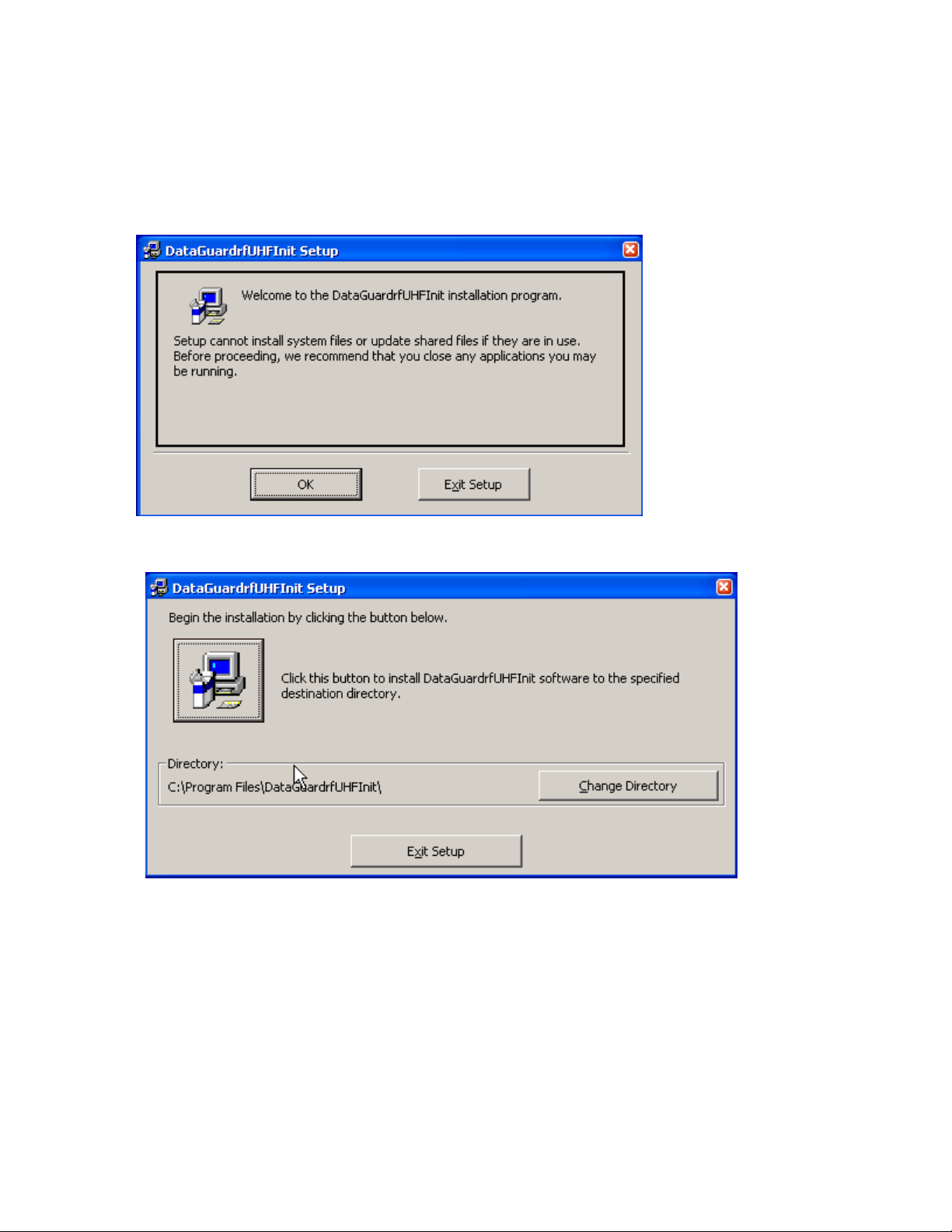
G. Once the program has launched the Welcome screen, click OK.
Figure 1
Figure 2
H. Select the installation folder where the DataGuard rf program will appear (Figure 2).
If you prefer the default Program Files folder, click the large button with the install
icon. If you prefer a different folder from the default folder, select that folder by
clicking the Change Directory button.
3
Page 4
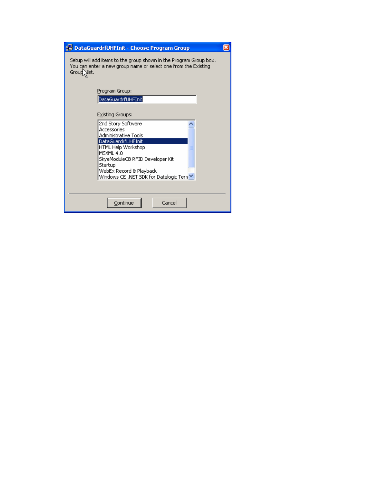
I. Choose the program group you wish to include the software in and press the
Continue button on the Choose Program Group Installation dialogue box (Figure 3)
to begin the installation. When the installation is complete, click on the OK button to
exit the installation set up of the software for the DataGuard rf UHF Automatic Label
Programmer.
Figure 3
Introduction
The Imation DataGuard rf UHF Automatic Label Programmer allows the user to write (“Program”)
the RFID tags embedded in barcode labels before the labels are removed from their printed
sheets. The programmer has twin laser readers that pick up the barcode information as the
labels pass below the readers and converts the laser barcode information to RFID identification
data. Twin RFID antennas use those identification data to initialize the RFID tags in the labels.
The RFID antennas can also read the RFID data in order to display the label information or to
verify that the laser barcodes are identical matches with the RFID tags.
The startup screen appears below.
4
Page 5
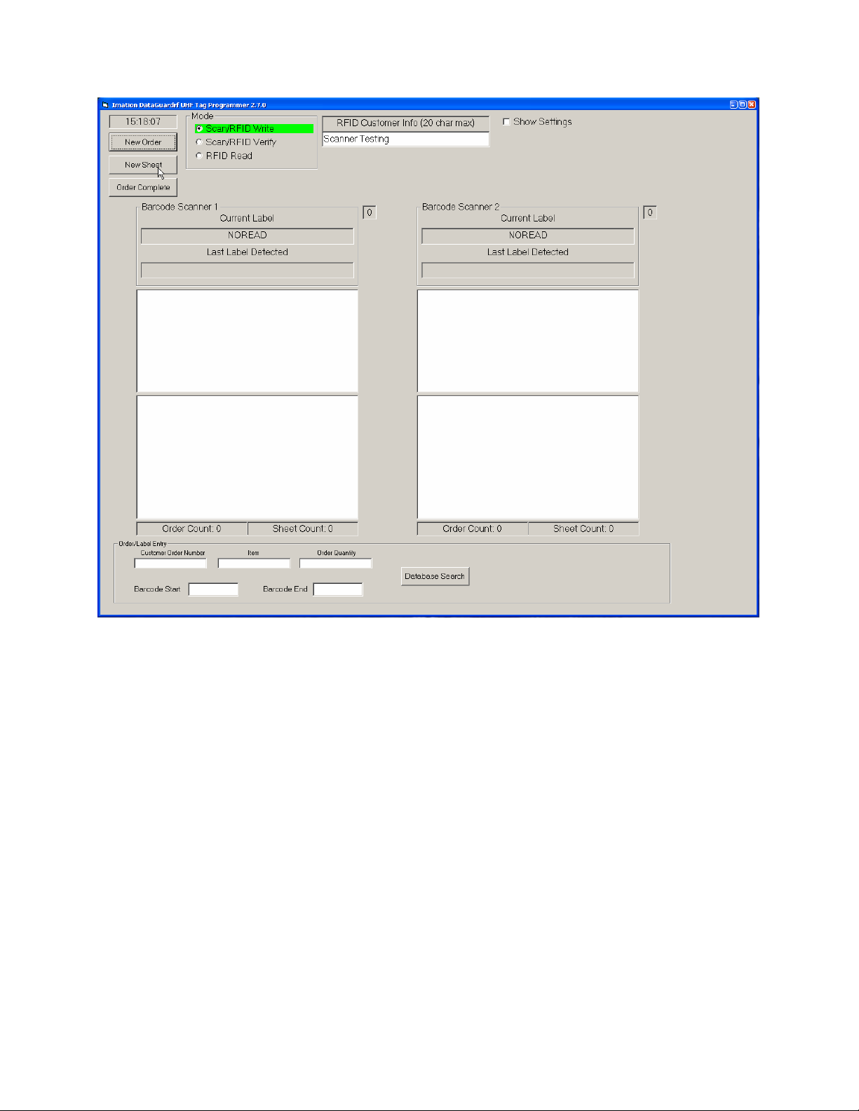
Figure 4
Before You Scan
Press the “New Order” button to initialize the software and prepare for scanning and
programming an entire order of RFID tags.
Order/Label Entry Info
Fill in the customer order number in the box labeled “Customer Order Number”.
Fill in the RFID lot number in the box labeled “Item”.
Fill in the total number of tags in the order in the box labeled “Order Quantity”. When the “Order
Complete” button is pressed at the end of the scan cycle the software will check to make sure
that the number of tags scanned and programmed equals the number of tags in the order.
Fill in the “Barcode Start” and “Barcode End” fields with the first and last VOLSER label ID’s in
the order. The software checks to make sure that all barcode labels read by the laser scanners
fall within this range before the RFID tag will be initialized. Be sure to include the media identifier
(“L1”, “L2”, etc) if present on the barcode label.
Fill in any additional information you may want to save about the order in the “RFID Customer
Info” field.
5
Page 6

It should be noted that the information in all of the above fields is optional. However, to get the
maximum benefit of the logging and error checking algorithms built into the software Imation
recommends that the info in the fields be entered prior to scanning.
1. Scan/RFID Write Mode
The Scan/RFID Write mode is the default mode. This mode is active when the software starts up,
when the “New Order” button is pressed, or when the “New Sheet” button is pressed. It allows
the user to scan labels printed with barcodes and convert those identification codes to RFID
codes while simultaneously writing them to the RFID tags embedded in the labels. Once the
program is in the Scan/RFID Write mode, place the sheet of labels on the programming station
as shown below. Place the sheet between the tabs of the belt. Then the top two barcode labels
will be under the laser scanners and the labels will be initialized (there is an audible confirmation
and the barcode number will appear in the lower window). Then the belt will slide the sheet up
until the next two labels are in the scan region and pause there until the labels are initialized. The
belt will continue to push until all the tags on the sheet are initialized.
Barcode Scanner 1 / Barcode Scanner 2
These two columns list the current barcode label being scanned in the upper box and the
last label detected in each column of labels on the printed sheet. The column
background areas turn green when a label is detected in its respective column. The label
identification number then appears in the respective column. Each column also includes
a list count of the number of labels successfully programmed.
Figure 5
6
Page 7

Figure 6
A small square to the right of each column contains a number identifying each step in the
label identification programming process. The numbers run from 0 to 5:
0 = No label is being detected
1 = The initializer is decoding the barcode with the laser scanner. At this point the
background turns green on each column that decodes the barcode.
2 = The initializer is detecting the RFID tag on each label.
3 = The initializer is trying to write to the RFID tag.
4 = The initializer is trying to write the “kill password” to the RFID tag.*
5 = The process is complete. The process is usually so quick that the user
generally sees only a 0 or a 5.
* A “kill password” prevents an accidental or malicious overwrite of the RFID tag that will alter its identification
number. Retail stores intentionally “kill” RFID tags as a security measure once an item bearing the tag has
been purchased.
7
Page 8
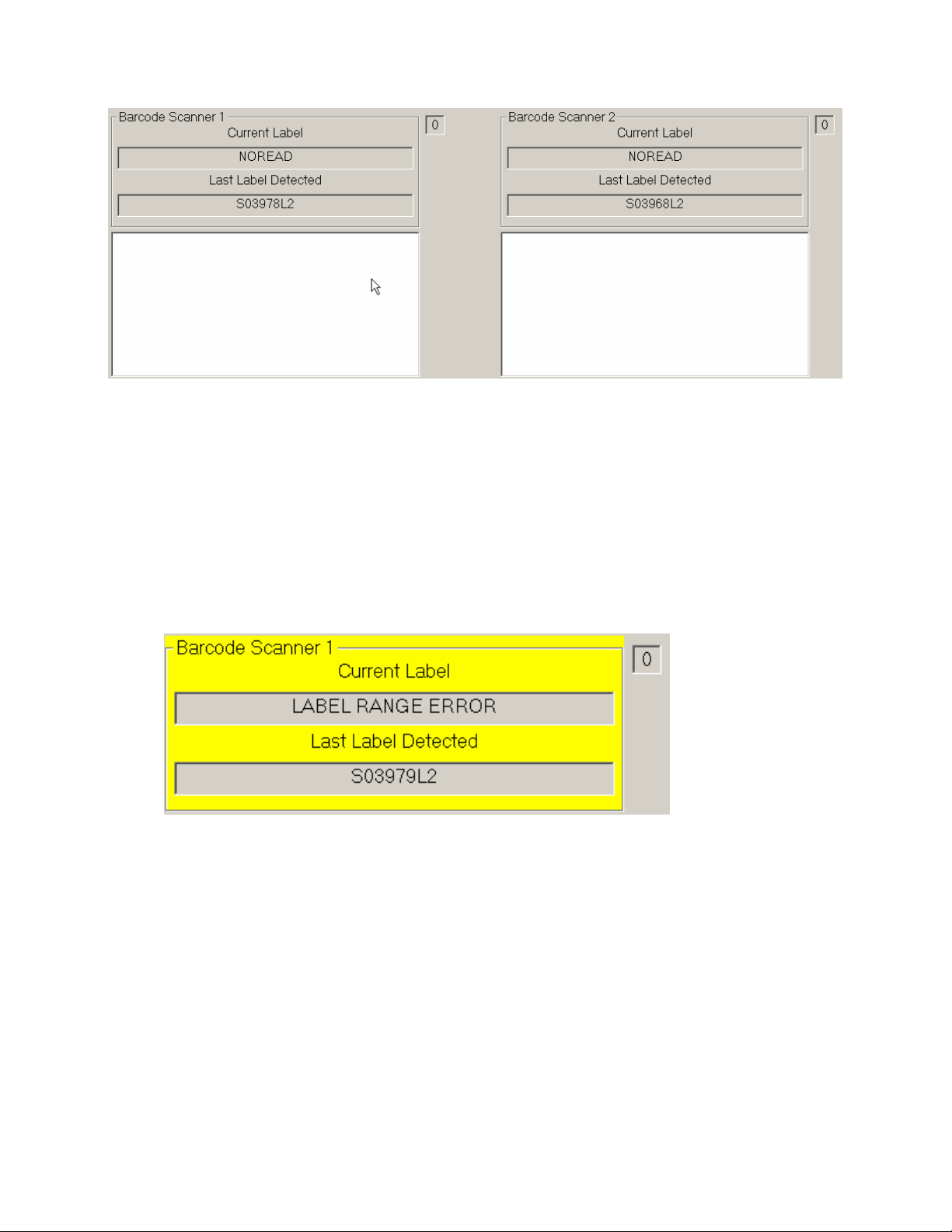
Figure 7
If one of the laser scanners cannot read the label currently under it, the “NOREAD”
message appears in the box as in the example above (Figure 7).
If the value of the barcode label being scanned by the laser scanner does not fall within
the range specified by the “Barcode Start” and “Barcode End” fields, the “Label Range
Error” message appears in the box as shown in the example below (Figure 8). Check to
make sure the sheet you are trying to program is the right one for the current order.
Adjust the “Barcode Start” and “Barcode End” fields as necessary to resolve the error if
the range was improperly specified.
Figure 8
2. Scan/RFID Verify
The Scan/RFID Verify option allows the user to make sure that both the printed barcode
identification number and the initialized RFID identification number match each other on each
label. The identifications can be mismatched if, for example, a . . . and the decoded barcode of
one label gets written to the following label accidentally. All initialized RFID labels should be
verified after being written.
The verification process is quick and simple.
1. After scanning and writing the entire sheet of twenty RFID tags, the “Scan/RFID Verify”
radio button will automatically be activated and the software will enter verify mode.
8
Page 9

2. The belt passes the sheet of labels below the laser scanners once again in the reverse
direction, pausing at each pair of labels until they have been verified.
3. The system will put a “VER” confirmation next to each label identification number
whenever the written RFID number matches the printed barcode ID, as in the example
below. An audible confirmation is also provided.
4. If the “VER” confirmation does not appear for any label—
a. Select the "Scan/RFID Verify" radio button again. If the “VER” confirmation still
does not appear:
b. Click on “New Sheet.” The following dialogue box (Figure 9) will appear:
c. Click OK to clear the sheet fields without adding the tags to the order list.
d. Repeat the RFID write and verify process for this sheet again.
e. Click Cancel to cancel the new sheet operation. You can then try again to verify
Figure 9
the tags that were missed.
9
Page 10

Figure 10
New Sheet
Clicking this button triggers a series of tests in the software in preparation for scanning a
new sheet of labels. If fewer than twenty tags were successfully written and verified since
the last time the “New Sheet” button was pressed the following warning will appear:
Press Yes to ignore this warning and continue to the next sheet. The tags listed in the
sheet results windows will be added to the order results windows. Press No to clear the
sheet results or press Cancel to go back and scan the rest of the tags on the sheet.
Figure 11
10
Page 11

If one or more of the tags was written but not verified the following warning will appear:
Press OK to clear the sheet results and rescan the sheet, or continue to the next sheet.
Press Cancel to go back and verify the tags that were missed on the current sheet.
Order Complete
Clicking this button triggers the tests for a new sheet as well as an additional test that
compares the total number of tags written and verified to the number of tags in the order.
If the totals do not match, the following warning will appear:
Figure 12
Press OK to ignore this warning and continue on to the next order or press Cancel to go
back and scan additional tags.
Figure 13
3. RFID Read
The RFID Read option allows the user to scan the RFID tags on the labels without regard for the
barcode label contents. The raw RFID tag information appears in each respective column. This
mode is useful for verifying that the RFID reader can read the chip contents.
11
Page 12

Show Settings
A check mark in this box brings up the settings to align the barcode laser readers, as well
as set other system options. Both the left and the right laser readers have adjustment
sliders that can adjust the start and stop positions of the laser scans. The user makes
these adjustments to correspond with the types of barcode/RFID label sheets.
Figure 14
12
Page 13

Figure 15: A screen shot with the settings check box active.
Left Laser Start and Stop / Right Laser Start and Stop
These settings are the adjustments for the laser scanners on the left and right
sides of the DataGuard rf UHF Automatic Label Programmer. Moving the sliders
under each column will visibly change the beginning and end points of each laser
scan line.
Adjust the scan lines by moving the sliders so that each line extends slightly
beyond the edges of its respective barcode label without interfering with the label
in the other column.
Left Scanner COM / Right Scanner COM
The communication or “COM” ports exist as virtual ports on the programmer. A
single USB cable links the programmer to the computer with the DataGuard rf
UHF software, and the selection of com ports is automatic. The user can
determine the communication ports for the laser scanners with these drop-down
options. The range is none to 15 for the left and right scanners.
Left RF COM port / Right RF COM port
The user can also determine the communication ports for the RF scanners with
these drop-down options. The range is none to 15 for the left and right scanners.
13
Page 14

Left RF Power / Right RF Power
The user can set the power level for the RFID scanners with these drop-down
options. The range is 0 to 220 for the left and right scanners. Imation will specify
a recommended power level for the tags we supply.
RFID Data Format
There are two options for the RFID format that is written to the RFID tags: JPMC format
and standard format. It is very important that the tags be written with the proper format, or
they will not be able to be read by the customer once they get into the field. Unless
specifically instructed in the order info, always use the standard format.
Database Search
The DataGuard rf UHF Tag Programming software records every tag written and verified in a file
based database (Dataguardrf.mdb) which is located in the program directory. The software
includes a simple front end to search the database, based on a number of user specified criteria,
and display the resulting records. You can also view and manipulate the database using
standard tools and programs available from Microsoft. Examples of programs with database
access capability include Excel, Access, and many others.
The database search criteria are combined in a logical AND fashion, that is, a given record must
satisfy all the specified search criteria in order to be included in the displayed results.
The database search and display tools in the programmer software are accessed by pressing
the button marked Database Search near the bottom of the main screen. The following screen
will appear:
14
Page 15

Figure 16
Start Date
The desired start date for the search can be specified in this field. It is possible to specify
a start date without an end date. If that is the case, the end date is taken as today’s date.
End Date
The desired end date for the search can be specified in this field. It is not possible to
specify an end date without a start date. If that is the case, an error will occur.
Barcode Label
The desired barcode label value for the search can be specified in this field. The barcode
label field must be an exact match.
Order Number
The desired order number for the search can be specified in this field. The order number
field must be an exact match.
Run Report
15
Page 16

Once you have specified the desired search criteria in the fields above, press this button
to search the database and display the results in the viewing window. The results will
appear as a scrollable list of database records that match the specified search criteria.
If you want, you can modify the search criteria and press the Run Report button again to
display results based on the new search criteria.
Close
Press this button to close the database search window and return to the main screen.
Figure 17
Troubleshooting Guide
The DataGuard rf UHF Tag Programming software may display the following error upon
startup:
16
Page 17

This error occurs when the software cannot find the reader hardware. Possible causes
and solutions are:
1) Power is not being supplied to the programmer.
Check to make sure the power cord is fully inserted into the programming unit.
Make sure the power switch on the programming unit is turned on.
Check to make sure the power cord is plugged into a live wall outlet. If the power cord is
plugged into an outlet strip, make sure the power switch on the outlet strip is turned on.
2) The software cannot communicate to the hardware over the USB cable.
Make sure a functioning USB cable is connected to the tag programming unit and the
computer running the tag programming software.
3) Software startup error.
Occasionally the software will have trouble talking to the hardware, especially right after
powerup.
In all these cases, click OK to exit the software. Once you have corrected the problem, try
restarting the software.
The software may also display the following errors upon startup:
Right RF reader not found!
Left Laser scanner not found!
Right Laser scanner not found!
There are 2 main causes for these errors, software startup errors and actual hardware
malfunction errors. Try clicking OK to exit the software and then restart it to see if the
error clears itself. If it doesn’t, the problem is most likely due to a hardware error and the
unit should be returned to Imation for servicing.
Occasionally Windows will display the following error when the programming unit is first
plugged into the USB port:
USB Device Error. A USB device attached to this port has malfunctioned or is not
recognized. Click here to troubleshoot.
Close the window by clicking on the X in the upper right hand corner. Remove the USB
cable from the device. Wait ten seconds, and then reinsert the cable in the device.
Figure 18
17
Page 18

Specifications
DataGuard rf UHF Automatic Label Programmer
Part Number 66-0000-9001-0
Physical Data:
Dimensions 75 x 31 x 22 cm (29.4 x 12.2 x 8.5 inches)
Weight 14 kg (31 lbs.)
Electrical Data:
Power adapter 100-240VAC 50-60HZ 1A
Programming station 12VDC 2.5A (TIP +, RING -) +12VDC ---o)--- GND
Operating frequency 902 to 928 MHz
Data Interface USB Type B Jack
Environmental Conditions:
Operating temperature 5° C to 40° C ( 40° F to + 105° F)
Storage temperature -25° C to +85° C (-10° F to +185° F)
Humidity 5%-80%, no condensation
RF Approval:
USA FCC 47 CFR Part 15.247
Canada RSS-210
USA
FCC ID: PB4DGPRG220
This device has been tested and found to comply with the limits for a Class A digital device,
pursuant to part 15 of the FCC Rules. These limits are designed to provide reasonable
protection against harmful interference when the equipment is operated in a commercial
environment. This equipment generates, uses, and can radiate radio frequency energy and, if
not installed and used in accordance with the instruction manual, may cause harmful
interference to radio communications. Operation of this equipment in a residential area is likely
to cause harmful interference in which case the user will be required to correct the interference
at his own expense.
Operation is subject to the following two conditions: (1) This device may not cause harmful
interference, and (2) this device must accept any interference received, including interference
that may cause undesired operation.
Modifying this device may void the user’s authority to operate the device.
CANADA
IC: 6900A-DGPRG220
The term "IC:" before the equipment certification number only signifies that the Industry
Canada technical specifications were met.
18
 Loading...