

Page 1
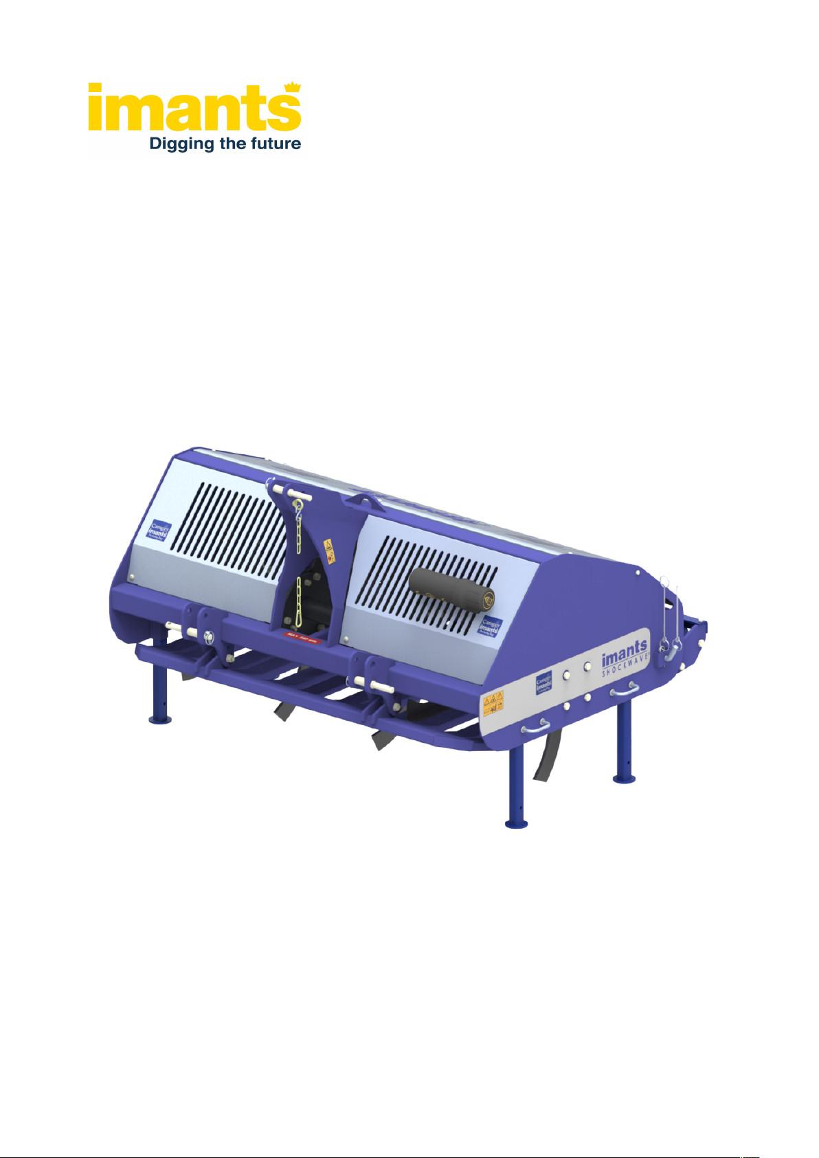
ShockWave
100 / 155 / 210
Manual
998-094-2
Original document
Page 2

Copyright © Imants® BV
Imants® BV reserves the right to alter parts at any desired moment, without prior or direct notification to the purchaser.
The contents of this document may equally be amended without prior warning.
For information about settings, maintenance work or repair that this document does not cover, you are recommended to contact your supplier’s service
department.
This document has been produced with the greatest of care. Imants® BV cannot, however, accept any responsibility for any errors in this document or
any consequences they may have.
All rights reserved. Nothing in this document may be duplicated, stored in an automated database, or made public, in any form or way, whether electronic,
mechanical, by photocopying, recording or in any other way, without prior written permission from Imants® BV. This also applies to the associated
drawings and diagrams.
Page 3
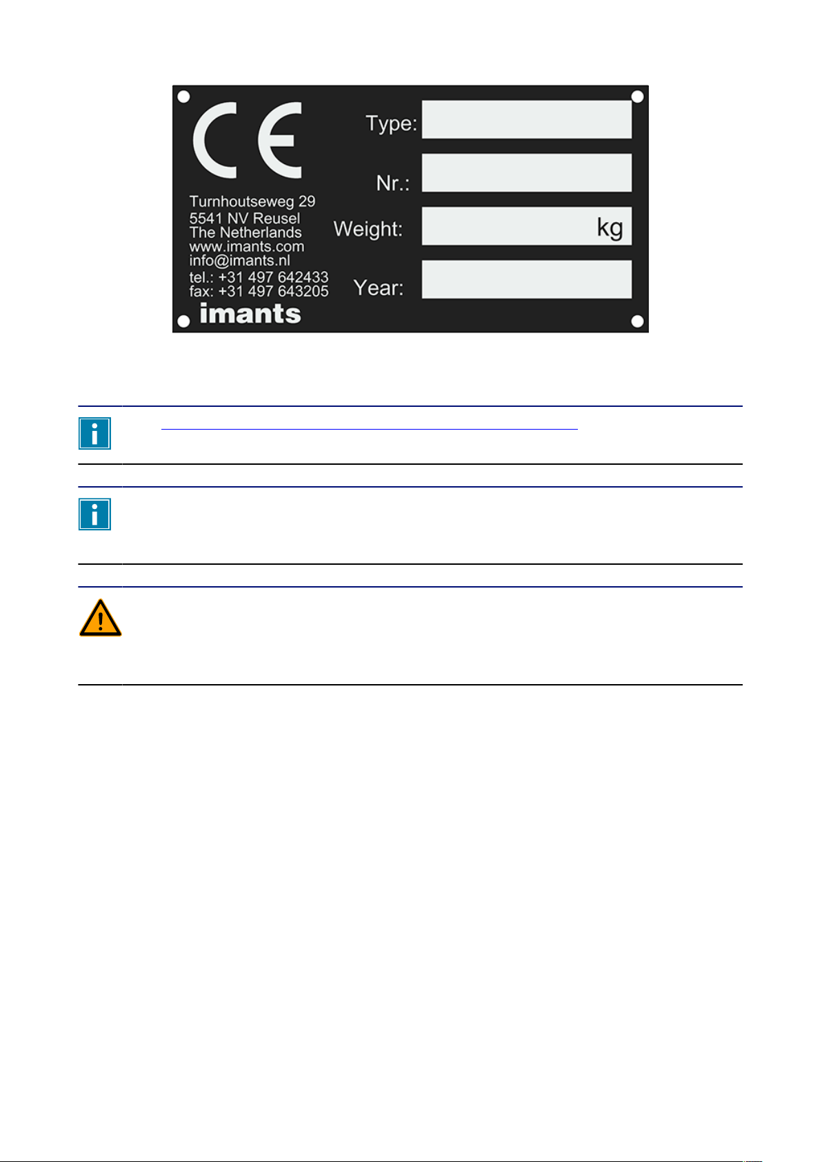
Illustration 1: Type plate
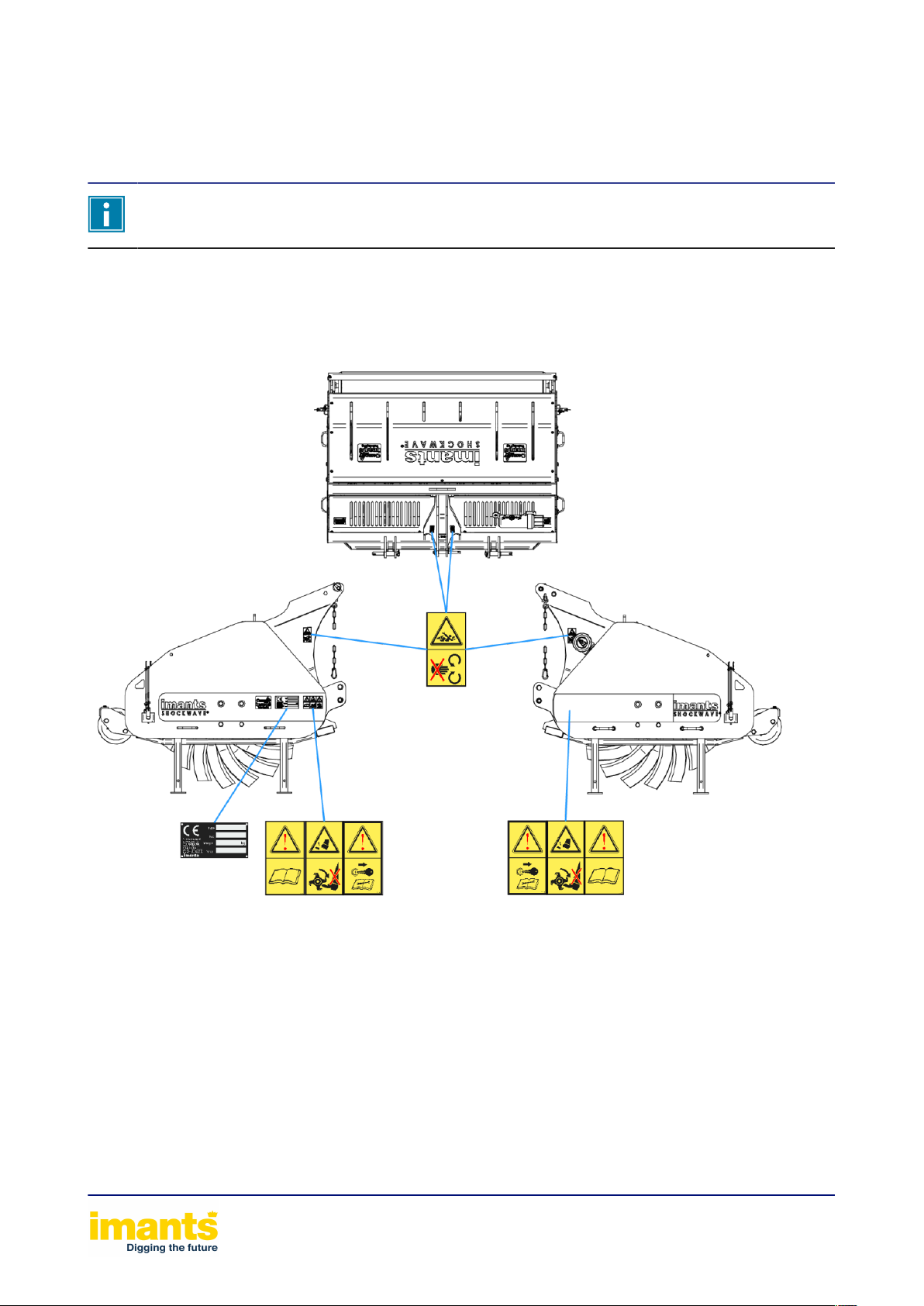
See Position of the warning stickers and type plate on the machineon page 14 for the
exact location of the type plate on the ShockWave.
Keep the details of your type plate in a safe location. If you have any questions about your
100 / 155 / 210ShockWave or wish to order parts, those specific details will allow us to help
you quickly and efficiently.
100 / 155 / 210
Carefully read the full contents of this document. A failure to do so may result in serious
injury or damage to the 100 / 155 / 210ShockWave. Keep this document in a safe place.
Always ensure that everybody who uses the 100 / 155 / 210ShockWave or performs
maintenance on it has read and understood the contents of this document.
Page 4

Page 5

Table of contents
1 Foreword........................................................................................................................................7
2 Safety instructions....................................................................................................................... 8
2.1 Explanation of pictograms...................................................................................................... 8
2.1.1 Hazard indications.......................................................................................................... 8
2.1.2 Meanings of pictograms................................................................................................. 9
2.1.3 Meanings of operating pictograms............................................................................... 10
2.2 General safety instructions................................................................................................... 11
2.3 Warning stickers on the machine......................................................................................... 13
2.4 Position of the warning stickers and type plate on the machine.......................................... 14
2.5 Operator’s responsibilities.................................................................................................... 15
3 Residual risks............................................................................................................................. 16
4 General description of machine............................................................................................... 17
5 Machine specifications.............................................................................................................. 18
5.1 ShockWave........................................................................................................................... 18
6 Loading and unloading the machine....................................................................................... 19
7 Putting the machine into operation..........................................................................................20
7.1 Putting the PTO shaft into operation....................................................................................21
8 Transport..................................................................................................................................... 22
9 Working with the machine.........................................................................................................23
9.1 Tractor settings..................................................................................................................... 25
9.2 Coupling the machine...........................................................................................................26
9.3 Machine settings................................................................................................................... 27
9.3.1 Fitting and configuring the coulters.............................................................................. 27
9.3.2 Runner.......................................................................................................................... 28
9.4 Starting and stopping work and settings.............................................................................. 29
9.5 Blocking the machine........................................................................................................... 31
9.6 Uncoupling the machine....................................................................................................... 32
10 Maintenance of the machine................................................................................................... 33
10.1 Daily inspection...................................................................................................................33
10.2 Drive train........................................................................................................................... 34
10.2.1 PTO drive shaft...........................................................................................................34
10.2.2 Gear box..................................................................................................................... 35
10.2.2.1 Middle gearbox................................................................................................... 36
10.3 Periodic maintenance and inspection: Checking the vent nipples..................................... 37
10.4 Wear parts.......................................................................................................................... 38
Table of contents 5
Page 6

10.4.1 ReplaceAeration blade................................................................................................38
11 Cleaning..................................................................................................................................... 39
12 Decommissioning..................................................................................................................... 40
13 Warranty.....................................................................................................................................41
14 Appendix/Appendices.............................................................................................................. 42
15 CE declaration...........................................................................................................................43
Table of contents 6
Page 7

1Foreword
First of all, we would like to congratulate you on purchasing a Imants® machine. You have
chosen a high-quality product. If used correctly, your machine will bring you many years of
enjoyment.
This Manual is an important document to ensure the machine is used correctly. It contains all the
information required to use the machine safely and optimally.
We recommend that you read this Manual thoroughly and that you study and follow all the
instructions before using the machine for the first time. The illustrations used in this Manual may
differ from the configuration of your machine; they are merely intended to explain a working
principle.
Please contact your point of sale/dealer should there be any questions or ambiguities as regards
this Manual.
We update our manuals regularly. Your suggestions help us to make our manuals even more user
friendly. You can e-mail your suggestions to [email protected] with ‘manuals’ in the subject line.
Imants® BV accepts no responsibility whatsoever for any damage or consequential damage due
to the incorrect use of the machine.
For this Manual, it is a “Original document”.
Foreword 7
Page 8

2Safety instructions
The machine has been carefully designed and professionally built to allow it to be worked with
safely. The CE Declaration confirms this. There are always however hazards and safety risks that
cannot be excluded. The functions of the machine and its operation by the operator give rise to
these hazards and risks.
This chapter covers the safety instructions and precautions, how these are brought to your
attention and with which the operator must comply. It is extremely important that you are properly
familiar with the safety instructions and rules and that you respect them in all circumstances!
2.1Explanation of pictograms
Pictograms are present under many headings in this manual. Symbols have also been applied to
the machine. In this chapter, you can see what these pictograms and symbols mean, what they
refer to, or what they are warning you about.
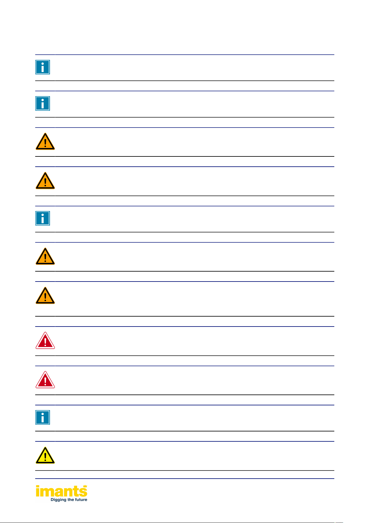
2.1.1Hazard indications
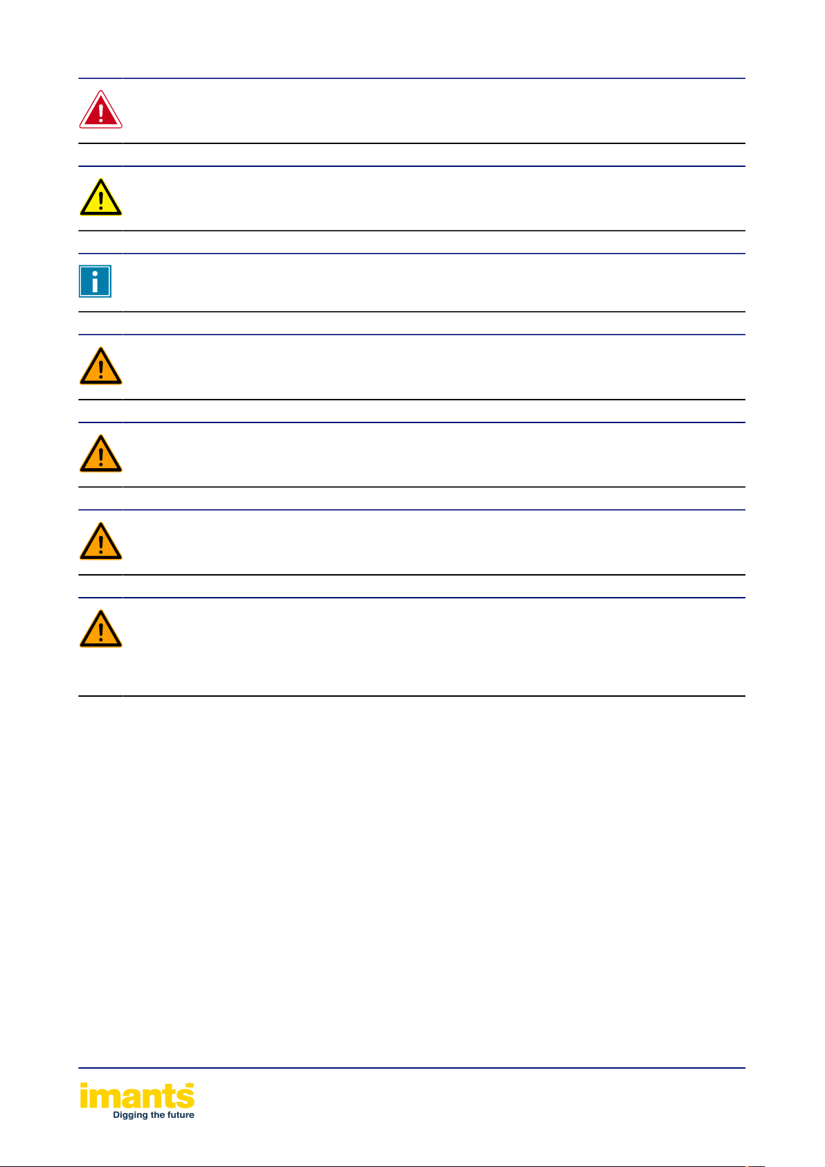
The symbols below indicate a possible danger of personal injury. The symbol is composed of an
equilateral triangle surrounding an exclamation mark.
Warning pictograms that are used in the Manual but are not present on the machine as stickers.
Warns of hazardous situations which must be avoided absolutely and are likely to result in
death or serious injury.
Warns of a hazardous situation that, if not avoided, could lead to death or serious injury.
Warns of a hazardous situation that, if not avoided, could lead to slight or more significant
injury.
This symbol is not a hazard symbol but rather an information symbol.
Provides additional information aimed at facilitating or improving the use of the machine.
Safety instructions 8
Page 9
2.1.2Meanings of pictograms
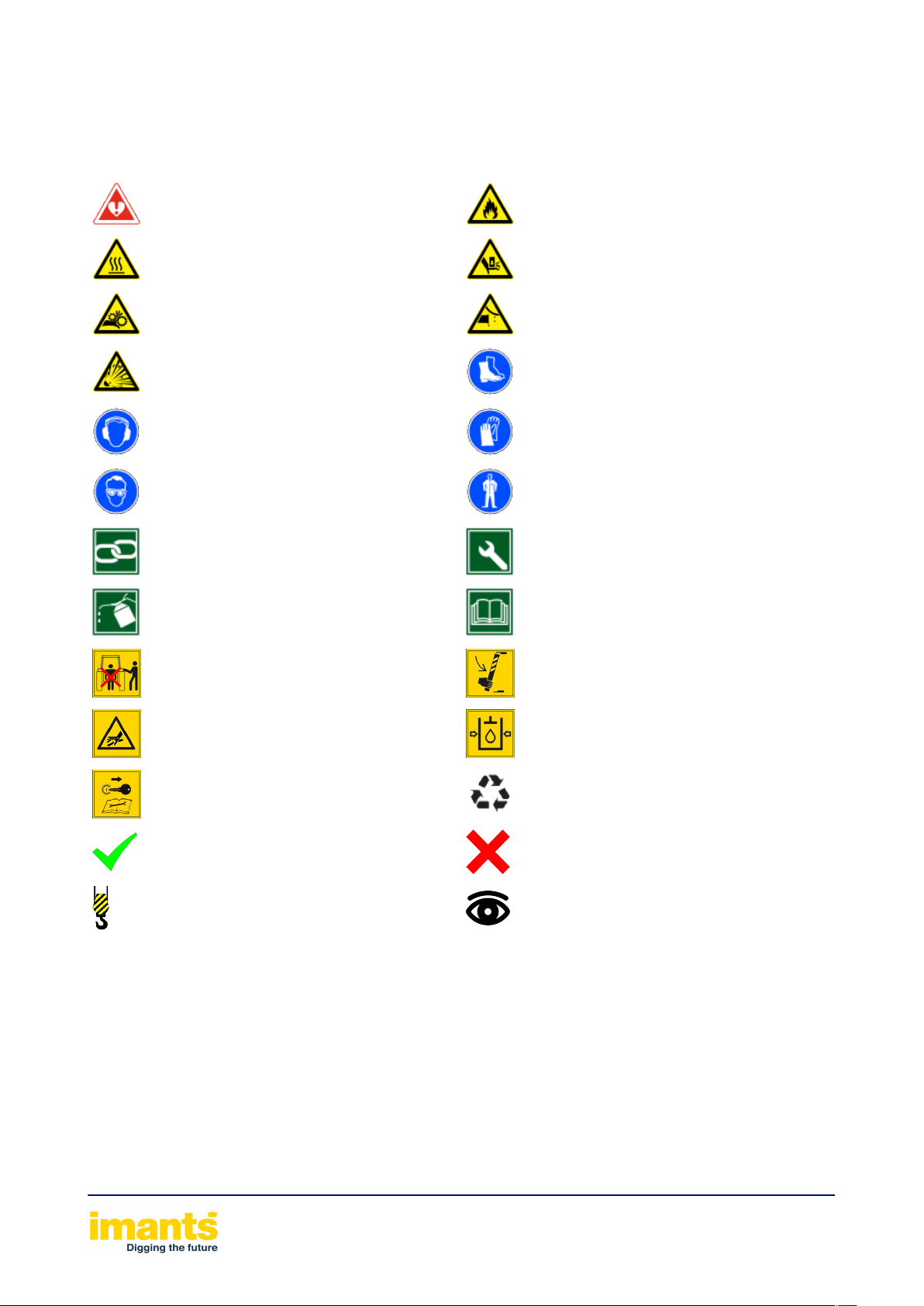
Below, you can see what the illustrations in the manual mean, what they refer to, or what they are
warning you about.
Danger of personal injury Fire hazard
Hot surfaces Trapping risk
Moving parts Leakage
Explosive substances Safety footwear
Hearing protection Gloves
Eye protection Clothing stipulations
Document reference Use of tools
Material use Read the manual
Danger of becoming trapped due to
being present within the lifting range
Danger from hydraulic oil under high
pressure as a result of leaking hydraulic
hoses!
Unintentional starting and rolling away
of the machine
Acceptable, correct Unacceptable, wrong
Use lifting hook Visual inspection
Danger of becoming trapped due to the
machine lowering unintentionally
Max. hydraulic system pressure
Recycle
Safety instructions 9
Page 10

2.1.3Meanings of operating pictograms
Operating pictograms indicate schematically what action must be taken or what setting must be
chosen.
The summary below includes all possible pictograms, which does not mean they are all used in
this Manual:
On Off
Hitch tension adjustment Hitch position adjustment
Hitch downwards Hitch upwards
Hitch working depth Pressure gauge
PTO on PTO off
PTO 1000 rpm PTO 540 rpm
Front wheel drive Direction of travel
Engage gear Engine speed down
Engine speed up Ram in floating position
Ram in Ram out
Safety instructions 10
Page 11
2.2General safety instructions
The user must hold a valid tractor driving licence in order to operate the machine.
The user must be at least 16 years old, unless the local legislation stipulates a higher
minimum age. The higher age limit shall prevail.
The user of the machine is responsible at all times for compliance with local safety
regulations and guidelines.
The user must have read through the whole contents of this manual and must follow to the
letter the instructions therein.
Keep this manual and that of the PTO drive shaft within reach.
Use the machine solely for the purpose it was designed for.
The machine may only be used and maintained by persons who are familiar with the
machine and have been made aware of the risks. No-one who could not be expected to
make correct use of the machine is to be permitted to commission or operate the machine.
No one should be standing between the machine and the tractor while these are being
coupled or uncoupled.
All safety facilities must be assembled on to the machine and be in good conditions. Never
remove or open a guard when the machine is running.
Always follow the specifications and requirements set by the manufacturer of the tractor in
relation to its use. Please refer to Tractor manual.
Always comply with the requirements regarding the maximum load of the front and rear
axles, given by the tractor manufacturer.
Safety instructions 11
Page 12
Standing on or within the range of the machine during work is prohibited. This also applies
during transport.
The maximum load of the tractor tyres, given by the tyre manufacturer, should not be
exceeded during operation of the machine.
Warning labels should always be legible.
Work may only be carried out under a raised machine if the machine has been properly
supported.
For reasons of quality and safety, only use original Imants® parts.
Maintain the machine as indicated later in the manual. Only perform this work when the
machine is at a complete stop. Remove the key from the tractor’s ignition.
Modifications, additions or developments on or to the machine are not allowed without the
written permission of Imants BV. This includes welding on load bearing parts. Without this
written authorisation, Imants BV’s responsibility for the CE marking is invalidated and is
passed on to the buyer.
Safety instructions 12
Page 13
2.3Warning stickers on the machine
See Position of the warning stickers and type plate on the machineon page 14 for the
position of the warning stickers.
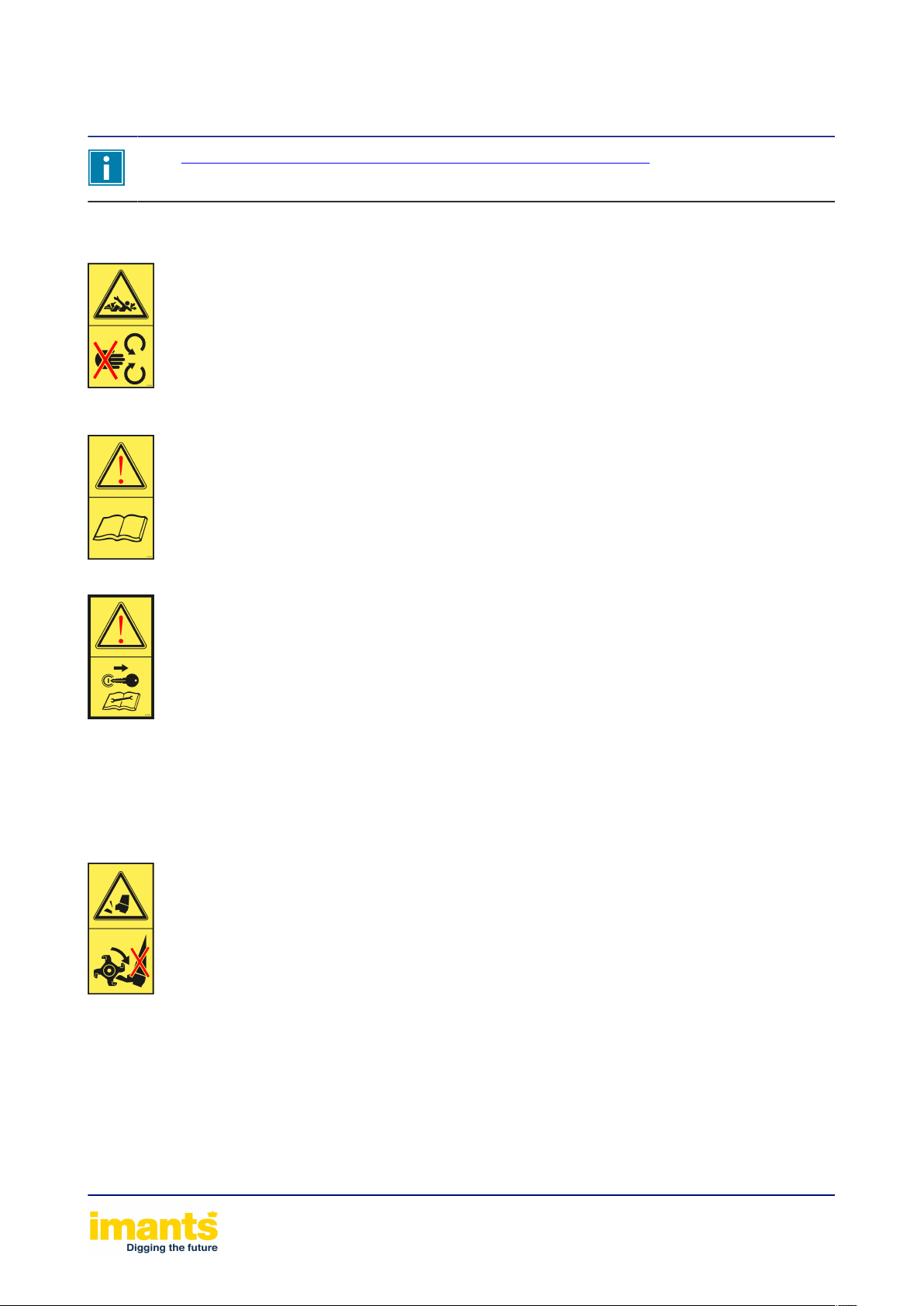
The warning stickers below can be found on the machine.
Danger of hands or arms being pulled in or locked in by the moving parts
of the power transmission.
It could cause serious injury, possibly leading to the loss of body parts.
Never open or remove the protective devices while the tractor engine is running
and the PTO drive shaft and/or hydraulic system are connected.
Read and observe the operating instructions and safety regulations before
you operate the machine.
Risk of the tractor and machine unexpectedly being started and rolling
away while work is being carried out on the machine, such as installation,
set-up, troubleshooting, cleaning, maintenance and repair work.
There is a risk of serious injury or even death.
• Before any intervention on the machine, protect the tractor and the
machine against being unintentionally started and against unintentional
rolling away.
• Read the relevant sections in the user manual and follow the
instructions.
Danger of feet being cut or torn off altogether. Keep away from exposed
moving parts that are part of the work process!
It could cause serious injury, possibly leading to the loss of body parts.
• Keep your feet away from the hazardous area while the tractor engine is
running and the PTO drive shaft and/or hydraulic system are connected.
• Wait until the machine’s moving parts come to a complete standstill
before you place your foot in the hazardous area.
Safety instructions 13
Page 14
2.4Position of the warning stickers and type plate on the
machine
Warning labels should always be legible.
The illustration below shows where the safety stickers and type plate are to be found on the
machine
Illustration 2: Position of the pictograms and type plate
Safety instructions 14
Page 15

2.5Operator’s responsibilities
It is the operator’s responsibility to ensure the machine is used safely. If the operator does not
obey the safety instructions and rules, serious physical injury and major damage to the machine
and the surroundings could be the result.
The operator must
• always be trained and qualified to operate the machine,
• remain alert and avoid hazardous situations,
• always conduct an inspection before use,
• conduct functional tests,
• check the workplace,
• keep bystanders at a safe distance,
• use the machine only for its intended purpose,
• wear the correct protective equipment and work clothing,
• not work under the influence of medicines, alcohol or drugs,
• be fully aware of the safety and usage rules, and
• know what the local government and official body instructions and rules are.
Safety instructions 15
Page 16

3Residual risks
The people operating the machine are responsible for ensuring the work is carried out
safely.
Every machine has inherent hazards. It is therefore always recommended to exercise the
greatest caution when working.
Even if all the safety precautions are taken and the machine is used in accordance with the
regulations, there are still residual risks:
Residual risks
• Contact with rotating parts of the machine.
• Material being ejected from the machine, which may cause an injury.
• Hinged parts, which may cause body parts being pinched.
• Human errors (e.g. fatigue, mental overload, etc.)
Residual risks 16
Page 17
4General description of machine
The machine has been designed for professional use:
• On sports fields and golf courses
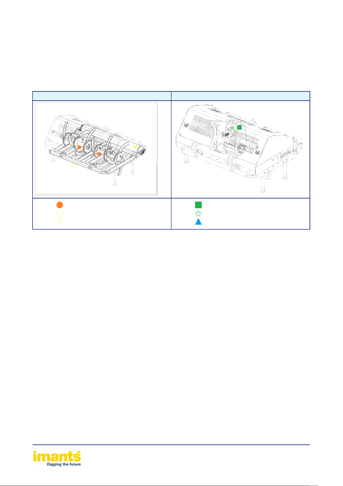
The machine is constructed as follows: Some parts are available as an optional extra.
Components Drive
•
•
•
Aeration shaft
Runner
Aeration blades
•
•
•
Main gearbox
Centre drive
Torque limiter
Table 1: Machine parts and drive
Depending on the model, the machine functions are as follows:
• Restoring/maintaining stretches of grass
A tractor provides the power needed to drive and tow the machine.
The power of the tractor is transferred to the machine via a: PTO drive shaft
The PTO shaft must rotate at: 540 revolutions per minute
The machine is operated from the tractor driver’s seat
The tractor’s three-point hitch is used to couple up the machine. The machine is fitted with coupling
points for a tractor with a lifting hitch of Category 1
General description of machine 17
Page 18

5Machine specifications
5.1ShockWave
ShockWave 1.00 ShockWave 1.55 ShockWave 2.10
Dimensions
Working width [mm](") 1000 39.4
Machine width [mm](") 1200 47.2 1750 68.9 2250 88.6
Machine length [mm](") 1350 53.1 1350 53.1 1350 53.1
1550
61.0
2100
82.7
Machine height (on legs) [mm](") 1150 42.3
Centre of gravity distance [mm](") 635 25
Weight
Machine weight [kg](lbs) 475 1045 580 1276 630 1386
Working speed
Max. working speed [Km/h](mph) 1.5 0.9 1.5 0.9 1.5 0.9
Working depth
Max. working depth [mm](") 250 9.8 250 9.8 250 9.8
Power
Min. power [KW(pK)]
Max. power [KW(pK)] 33 (45) 36 (50) 44 (60)
PTO drive shaft
Rotational speed of the
drive
PTO drive shaft type W2300 W2300 W2300
Torque limiter protection [Nm](lbf ft) 850 630 850 630 850 630
[/min](rpm) 540 540 540
18 (25) 22 (30) 30 (40)
1150
635
42.3 1135 42.3
25 635 25
Noise level
Noise level dB(A) < 80 < 80 < 80
Machine specifications 18
Page 19
6Loading and unloading the machine
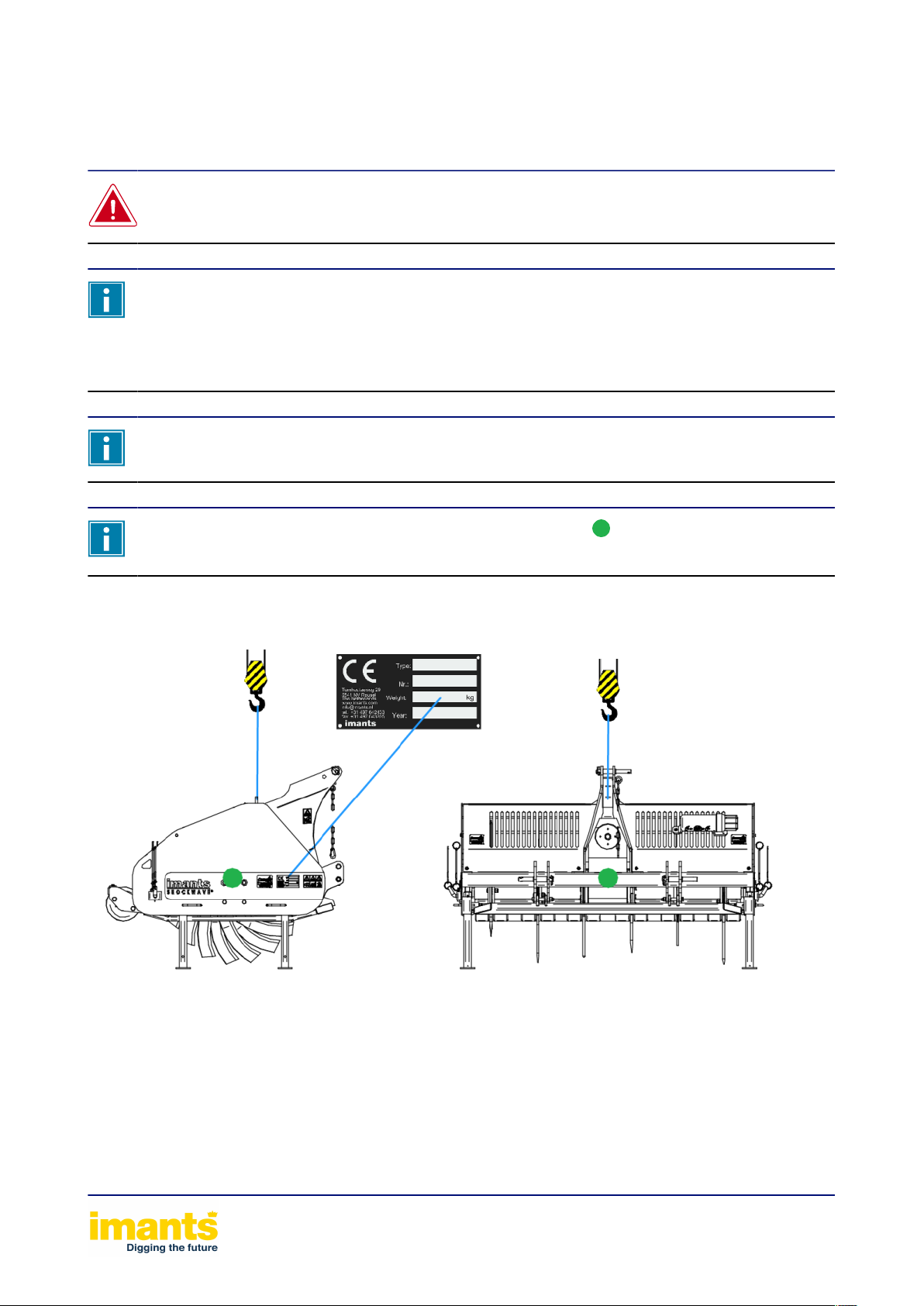
Never go under a hoisted-up machine.
Use only approved lifting equipment (wire ropes, belts, chains, etc.) that:
• have a permissible load that is greater than the weight of the machine, see type
plate
• do not have any defects.
Only qualified personnel should hoist machines.
The machine’s centre of gravity is indicated by the symbol: This is for a standard
machine without options
Loading and unloading the machine 19
Page 20

7Putting the machine into operation
The user must have read through the whole contents of this manual and must follow to the
letter the instructions therein.
20% of the unladen weight of the tractor must always rest on the front axle.
A PTO drive shaft of the wrong length may cause serious damage to the tractor and the
machine. This would invalidate the CE marking of the PTO drive shaft. Putting the PTO
shaft into operationon page 21
Connect the overload clutch according to the instructions provided by the manufacturer of
the PTO drive shaft.
Check whether the clearance around the PTO drive shaft is sufficient whatever the
operating conditions. The PTO drive shaft will become damaged if there is too little
clearance.
Procedure
1. Check:
• That all bolted connections are tight
• The oil level in the gearbox(es)
2. Couple the machine up to the tractor (see section on coupling and uncoupling)
3. Do not connect the PTO drive shaft yet
4. Carefully read the manufacturer’s instructions for the PTO drive shaft
5. Shorten the PTO drive shaft Putting the PTO shaft into operationon page 21
6. Connect the PTO shaft to the tractor
7. Fit the coulter set
Putting the machine into operation 20
Page 21

7.1Putting the PTO shaft into operation
The PTO shaft is an essential part of the machine.
There are a number of matters that need to be watched out for:
• See PTO drive shaft manual
• of http://www.gkn-walterscheid.de/downloads/anleitungen
Points of attention
1. The length of the PTO shaft.
• With the shortest operating distance between the tractor and the machine, the PTO shaft
• The minimum profile overlap is: See PTO shaft manual
2. Attach overloading/freewheel clutch or bolt connection (conical) at the machine end
must still be able to slide in by 40mm / 1.6 inch . In this, account must be taken of:
• A hydraulic top link (if present) in its shortest position
Putting the machine into operation 21
Page 22

8Transport
20% of the unladen weight of the tractor must always rest on the front axle.
The machine may be transported on the public road while on the tractor.
Information concerning local traffic regulations must be obtained in advance.
This information could include matters such as:
• Maximum transport width;
• Maximum axle load;
• Lighting to be shown;
• Use of warning signs.
Before the tractor-machine combination goes on a public road at least check the following:
1. That the top link and draw bar pins are secured with a linch pin
2. That the legs are raised and secured
3. That the lighting works, is undamaged and properly visible
4. That the braking system works properly
5. That the supply lines are correctly connected
Transport 22
Page 23
9Working with the machine
The operating speed must be adjusted to suit the soil and working conditions.
The machine is only suitable for treating soil and fields that are free of obstacles, such as
stones, tree stumps, steel objects, etc.
Only engage the PTO if there is nobody in the machine’s danger zone.
While working with the machine, never depress the clutch pedal, nor take the tractor out
of gear. The machine could actually push the tractor forward. This could lead to hazardous
situations.
It is not permitted to stand on the machine or to stand within the range of the machine
while the machine is in use. This also applies during transport.
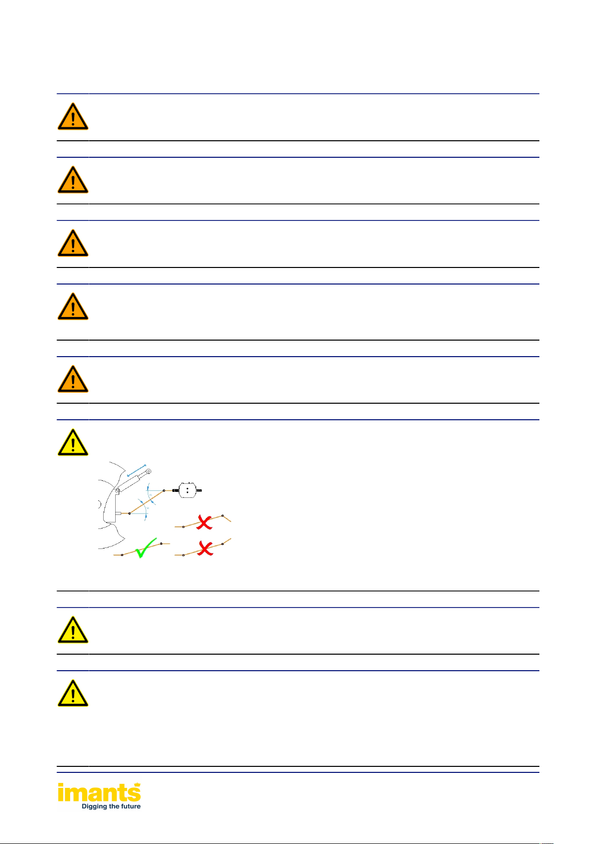
Risk of additional wear of the PTO drive shaft if the shaft angles are unequal.
Take into account the permissible angle rotations of the rotating PTO drive shaft.
Limit the lifting height. The sudden excessive lifting of a powered machine can cause
serious damage to the:
• PTO
• PTO drive shaft
• gear box
Working with the machine 23
Page 24

Immediately turn off the PTO if the raised machine runs erratically.
Friction with the soil may cause the wear parts to become very hot.
Working with the machine 24
Page 25

9.1Tractor settings
• Ensure there is sufficient weight at the front of the tractor
• Ensure the tyre pressures are equal
• Place the lifting arms at the same height.
• Put the lowering speed of the hitch to slow
• Select the correct PTO speed: 540 revolutions per minute
Working with the machine 25
Page 26

9.2Coupling the machine
In order to use the machine it must first be coupled up
1. Set the tractor lift arms at equal height
2. Check that the PTO drive shaft slides in and out easily (lubricate!)
3. Send people away from the danger area between the tractor and the machine
4. Drive the tractor close to the machine, leaving about 25 cm of room between the tractor and the
5. Secure the tractor to prevent unintended starting or rolling away
6. Connect the PTO shaft
7. Reverse further with the tractor towards the machine
8. Connect the three-point hitch to the machine’s coupling points. Ensure the coupling points are
9. Use the stabilizer rods to secure the tractor’s lifting arms
10. Raise the machine so that it is in the transport position. Be aware of the max. lifting height
11. Raise support legs up and lock them again with a linch pin
12. When checking the free space around the PTO drive shaft, make sure there is enough space at
13. By performing a visual inspection, check that the three-point hitch is properly locked before driving
machine
properly secured
the hitch bar!
away
Working with the machine 26
Page 27
9.3Machine settings
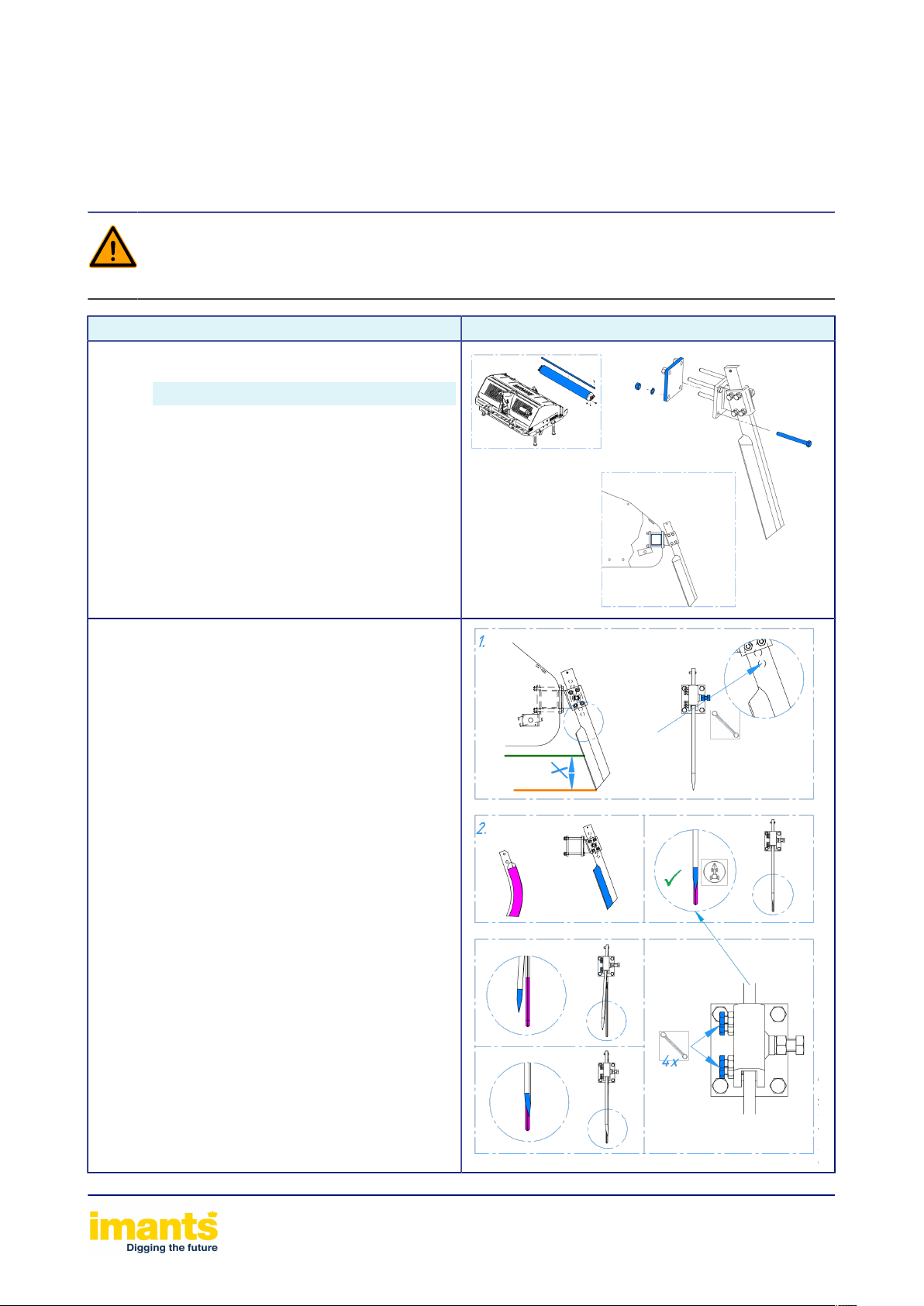
9.3.1Fitting and configuring the coulters
Before carrying out maintenance work or changing the machine’s settings, it must have
come to a complete standstill. The tractor’s engine must be switched off and the key must
have been removed from the ignition.
Procedure Illustration
1. Disassemble the running roller. Pay
2. Fit the coulters
1. Set the working depth
2. Align the coulters with the scarifying blades
attention to the weight!
Type Weight [kg] / (lbs)
SW100 30 / 65
SW155 40 / 90
SW210 55 / 120
Working with the machine 27
Page 28
9.3.2Runner
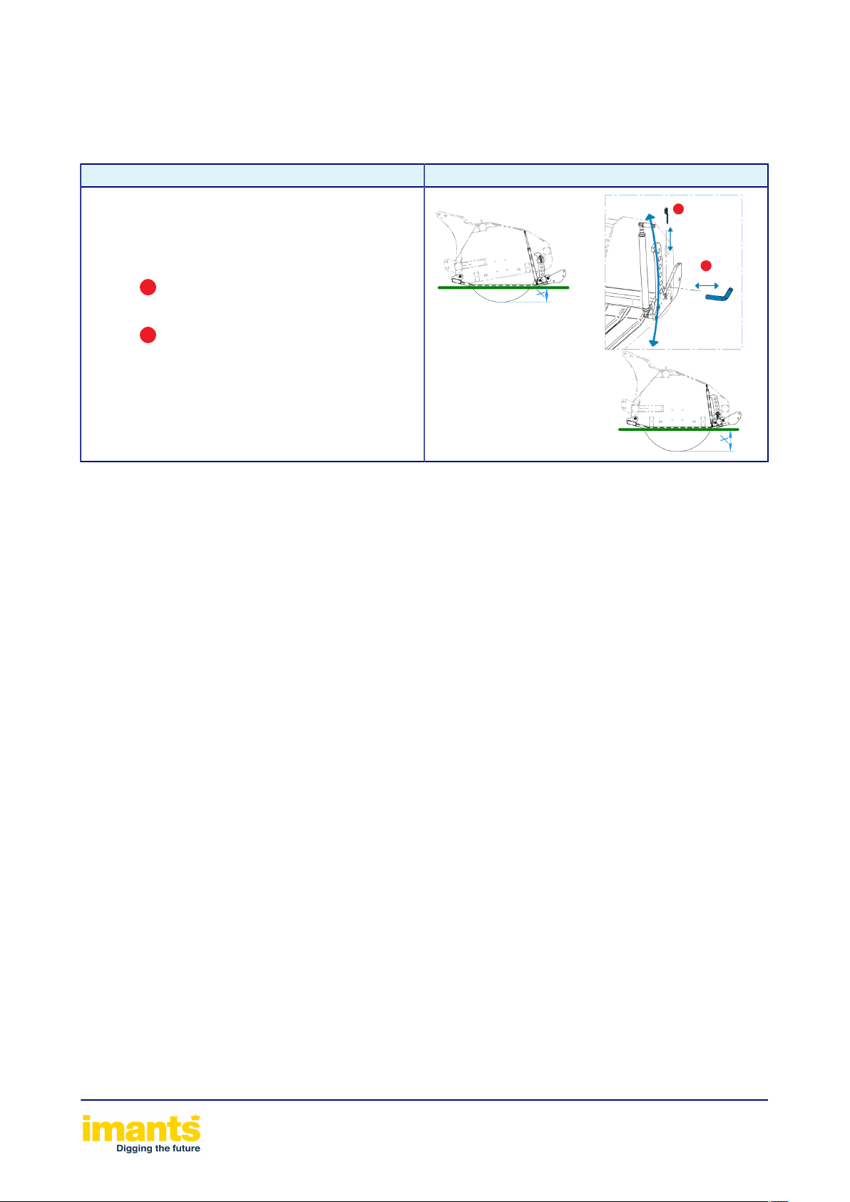
The machine rests on the runner pack. The working depth is adjusted by adjusting the runner pack.
A running roller is attached to the runner pack.
Procedure Illustration
1. Raise the machine
2. During all operational activities, make
3. Secure the tractor to prevent unintended
4.
5. Use the pins to set the correct working
6.
7. Lift the runner until the pins block the
8. The working depth is now set.
sure the machine cannot roll away
unintentionally.
starting or rolling away
Remove linch pin
depth.
Fit linch pin
runner.
Working with the machine 28
Page 29

9.4Starting and stopping work and settings
Working with the machine is described in the two tables below. Actions that recur during every job
for starting and stopping are shown printed in bold. One-off settings are printed normally. Some
of the instructions may concern an optional extra that your machine may not have.
The machine must never be turned on when the driven rotor is placed on the ground. This
can result in serious damage to the tractor and the machine.
1. Check that the correct PTO speed is engaged: 540 revolutions per minute
2. Adjust height of runner Runneron page 28
3. Drive forwards.
4. Slowly lower the machine while it is moving and the engine is revving slowly.
5. Engage the PTO just before the rotor contacts the ground
6. Gradually increase the engine speed and the driving speed Optimum driving speed
7. After 20 metres, check the machine’s working depth.
8. If the working depth is correct, go to next step, otherwise change the working depth
a. Readjust height of runner Runneron page 28
b. Recheck working depth. If working depth is correct, continue work or go through this step
again
Table 2: Starting the machine and configuring the settings
1. Reduce the travelling speed
2. Reduce the engine revs
3. Raise the machine out of the ground in a smooth motion while the machine is moving.
4. Switch the PTO off during lifting
Table 3: End of job, stopping the machine (and settings)
The machine’s working speed depends on:
• The depth of the tillage
• Type of soil
• Soil condition (wet, dry)
• Compacting (disruptive layers)
Damage to the turf layer:
• Blades crooked
• Blades not aligned
• Do not drive straight forward
Working with the machine 29
Page 30

*)= If present **)= Optional
Working with the machine 30
Page 31
9.5Blocking the machine
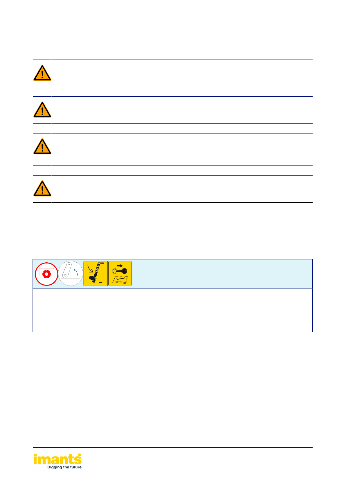
Apply the tractor’s handbrake so that it cannot roll away.
Work may only be carried out under a raised machine if the machine has been properly
supported.
Before carrying out maintenance work or changing the machine’s settings, it must have
come to a complete standstill. The tractor’s engine must be switched off and the key must
have been removed from the ignition.
Be aware of residual mechanical, hydraulic, pneumatic and electrical energy present in the
machine.
The machine may come to a halt because it is full, or because of stones or other obstacles.
To prevent damage to the transmission, the PTO drive shaft is fitted with an overload protection
device.
A rattling noise is heard when the torque limiter is engaged.
1. Immediately disengage the PTO drive shaft
2. Raise the machine fully out of the ground.
3. Place the support legs under the machine
4. Place the machine on the ground and turn off the tractor engine.
5. Remove the obstacle from the ground or the machine.
6. Start tilling on the newly prepared section of soil.
Working with the machine 31
Page 32

9.6Uncoupling the machine
Be aware of residual mechanical, hydraulic, pneumatic and electrical energy present in the
machine.
1. Lower the machine’s support legs and secure them again with a linch pin
2. Place the machine on a flat, stable surface
3. Secure the tractor to prevent unintended starting or rolling away
4. Disengage the three-point hitch
5. Drive the tractor forward about 25 cm
6. Disconnect the PTO shaft
Working with the machine 32
Page 33
10Maintenance of the machine
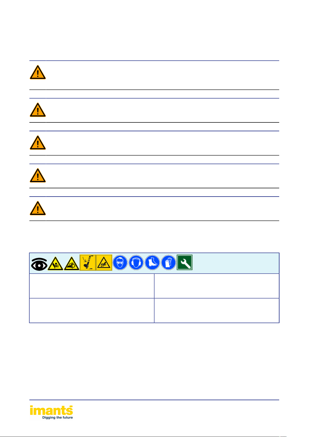
Never use your hand or fingers to try to stop a leak in the hydraulic system. Fluid escaping
under pressure (hydraulic oil) could enter the body through the skin and cause serious
injury. Consult a doctor immediately in case of wounds from hydraulic oil!
Avoid dangerous situations. Repair broken or worn parts before using the machine.
Be aware of residual mechanical, hydraulic, pneumatic and electrical energy present in the
machine.
Work may only be carried out under a raised machine if the machine has been properly
supported.
For reasons of quality and safety, only use original Imants® parts.
10.1Daily inspection
General
• Warning stickers
• Loose bolted connections
Wear parts
• Aeration blade
Guards
• PTO drive shaft guard(s)
• Runner
Drive
• Oil level in gearbox(es)
• Vent nipples
Maintenance of the machine 33
Page 34

10.2Drive train
The drive train comprises the following components:
10.2.1PTO drive shaft
Keep the PTO drive shaft clean. Lubricate sliding parts so that the PTO drive shaft can
slide in and out easily.
• Consult the PTO shaft manual for its maintenance
• of http://www.gkn-walterscheid.de/downloads/anleitungen
Maintenance of the machine 34
Page 35

10.2.2Gear box
The gearbox is filled with running-in oil. This should be changed after 50 operating hours.
See oil type in table below
Position indications on the machine are always expressed as seen from the rear of the
machine.
Dispose of the waste oil in an environmentally responsible manner. To do so, follow the
local statutory regulations in force
Check the oil level
1. Set the gear box to be horizontal
2. The oil level must be in the middle of the sight glass of the level plug
3. The oil level should be at the bottom of the level plug
Change the oil
1. Place a collection pan under the gear box
2. Check the vent plug for correct operation
3. Open the drain plug.
4. Drain all the oil
5. Screw the drain plug back in and fill the gearbox
6. Screw the vent and filler plugs back in
Maintenance of the machine 35
Page 36
10.2.2.1Middle gearbox
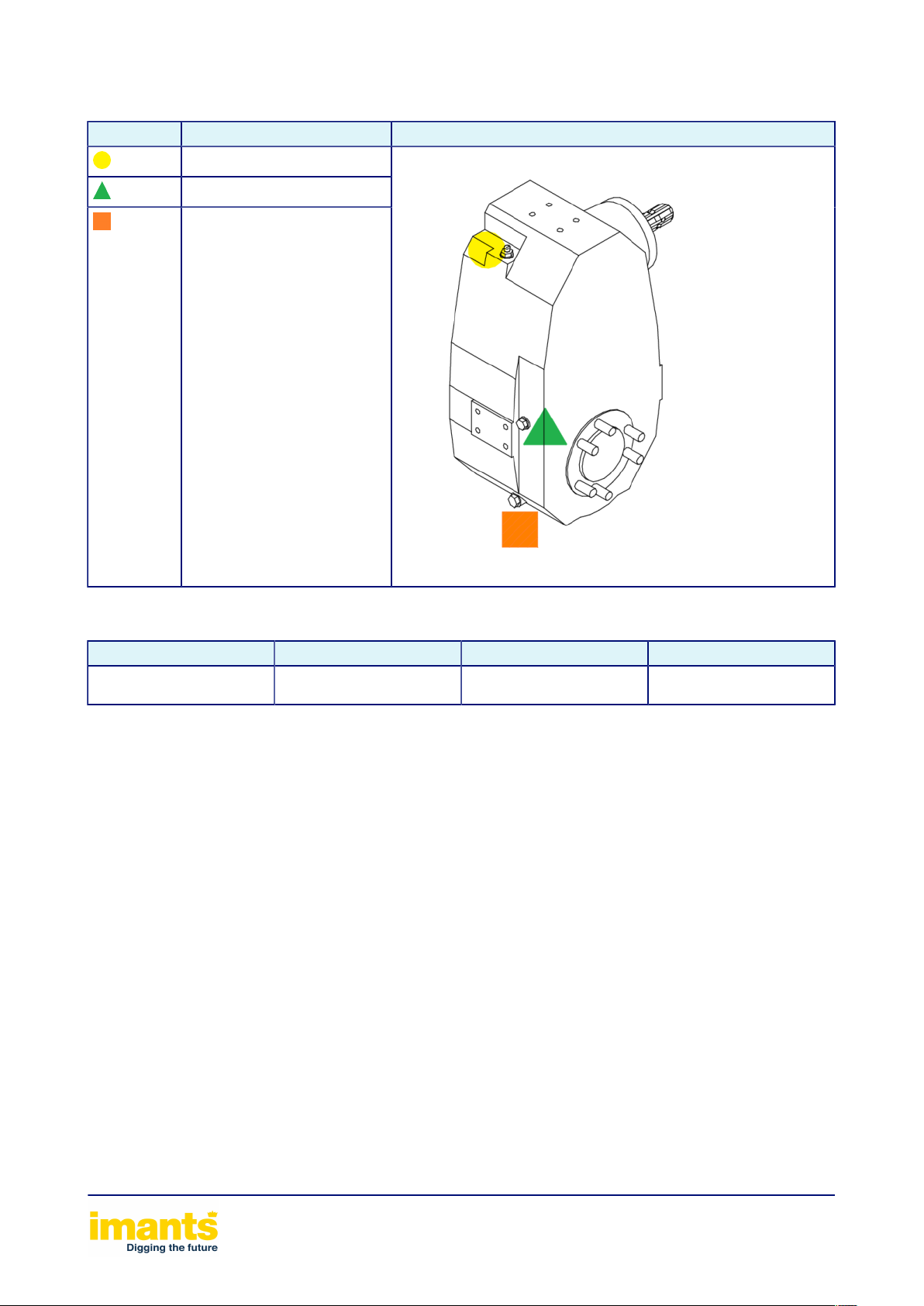
Symbol Description Gearbox type
Vent plug / filler plug
Level plug
Drain plug
Table 4: Oil level legend6020-M-1
Gearbox type Oil type Oil volume Maintenance interval
010963: 6020-M-1 MobilGear 600XP320 3.5 [L] / 0.9 (USgal) 12 months or 500
operating hours
Table 5: Gearbox filling details and maintenance interval6020-M-1
Maintenance of the machine 36
Page 37

10.3Periodic maintenance and inspection: Checking the vent
nipples
Symbol Number of bleed nipples Maintenance interval
1( Main gearbox) 12 months or 500 operating hours
Table 6: Checking the vent nipples
Maintenance of the machine 37
Page 38
10.4Wear parts
10.4.1ReplaceAeration blade
Before carrying out maintenance work or changing the machine’s settings, it must have
come to a complete standstill. The tractor’s engine must be switched off and the key must
have been removed from the ignition.
For reasons of quality and safety, only use original Imants® parts.
Dispose of any worn components in an environmentally responsible manner. Always
follow the locally applicable statutory regulations.
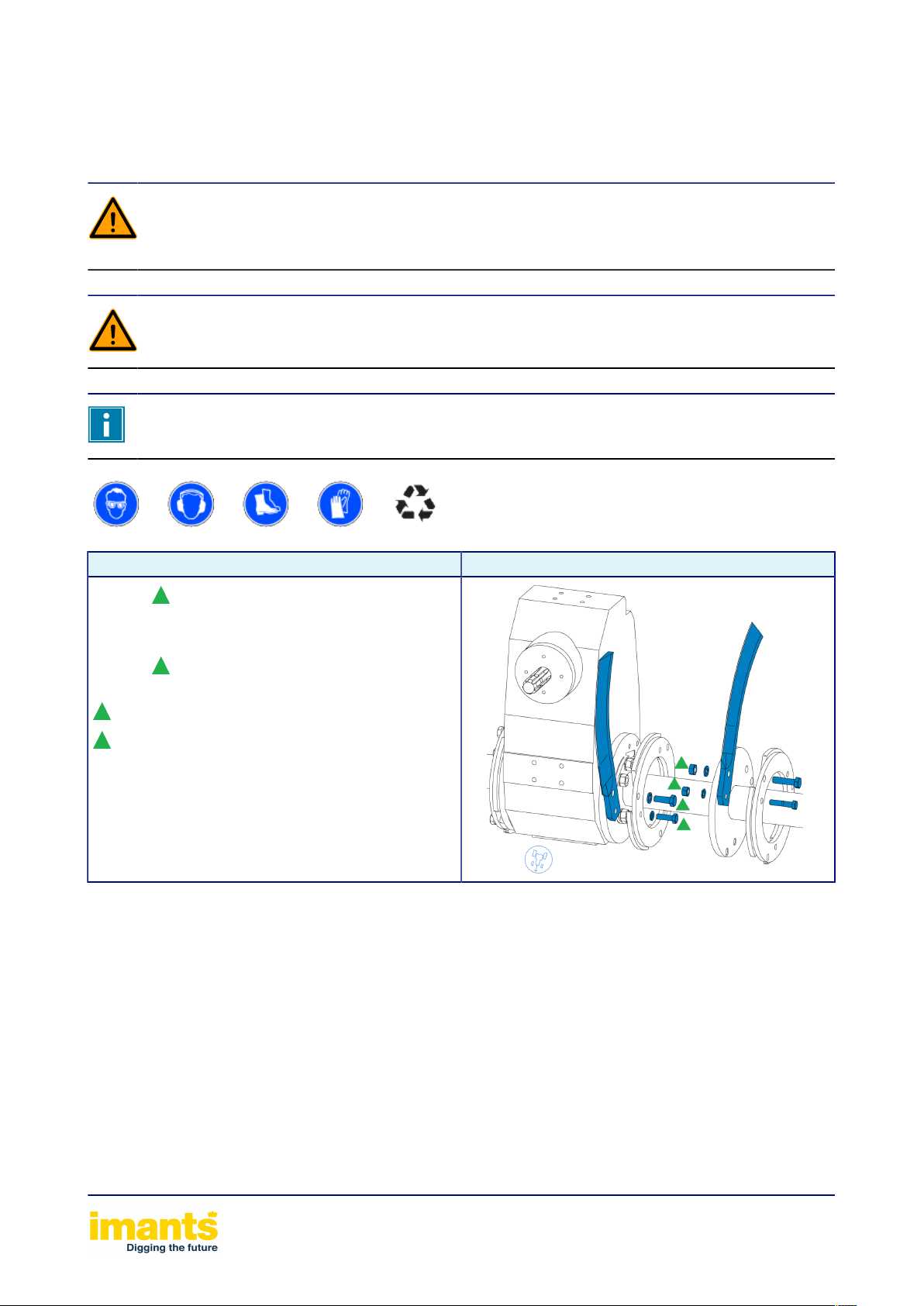
Procedure Illustration
1.
2. RemoveAeration blade
3. Clean wear and tear part holder
4. InstallAeration blade
5.
6. Bolt connection torque:
M14: 135 [Nm] / 100 (lbf ft)
M12: 86 [Nm] / 64 (lbf ft)
Remove bolt connection
Do up bolt connection
Table 7: Aeration blade
Maintenance of the machine 38
Page 39

11Cleaning
Never clean a machine while it is in operation. There is a risk of serious injury or even
death.
Carefully check hydraulic hoses and electrical cables.
Never treat hydraulic hoses and electric cables with gasoline, benzene, petroleum or
mineral oils.
Lubricate the machine after cleaning it. Especially after the machine has been cleaned
using a high-pressure cleaner/steamer or fat-soluble agents.
Observe the legal requirements concerning the use and disposal of cleaning agents.
When cleaning with a high-pressure cleaner, you must always follow the instructions below:
1. Maximum permitted pressure is 100 bar.
2. The maximum temperature is 50 °C
3. Do not clean the electrical components.
4. Never direct the jet of the high-pressure cleaner or steamer directly at the stickers,
lubricating points or bearings.
5. Keep the high-pressure cleaner/steamer a minimum distance of 600 mm away from the
machine.
6. Observe the safety regulations for the use of high-pressure cleaners.
Cleaning 39
Page 40

12Decommissioning
When the machine is decommissioned, the parts can be sorted as follows:
1. Metals
2. Plastics
3. Oils and greases
Dispose of the sorted materials in an environmentally responsible manner. Always
follow the locally applicable statutory regulations.
Decommissioning 40
Page 41

13Warranty
IMANTS BV warranty information
(A) Warranty
IMANTS BV guarantees that none of the products that it manufactures has any material faults and IMANTS BV issues
a warranty for the manufactured products at the time of shipment, which is valid for a period of twelve (12) months from
the date of delivery to the customer. IMANTS BV delivers replacement parts, free of charge, for all parts that IMANTS
BV considers to be faulty at the time of shipment. Alternatively, IMANTS BV can opt to repair such components or have
such components repaired on its behalf on the condition that such components are returned on request to the factory
at Turnhoutseweg 29, 5541 NV, Reusel, the Netherlands. The transport costs for the return shipment must be paid in
advance.
This warranty does not apply to any products that have been subject to incorrect use, incorrect application, negligence
(including, but not limited to, incorrect maintenance), an accident, incorrect installation, a modification (including, but not
limited to, the use of components or add-on components for which permission has not been granted), an alteration or
repair. Motors and all accessories that are delivered with products from IMANTS BV but which are not manufactured
by IMANTS BV are not covered by the warranty issued by IMANTS BV. They are only sold with the explicit warranty, if
there is one, issued by the manufacturer concerned. THE ABOVE REPLACES ALL OTHER WARRANTIES, EITHER
EXPLICITLY OR IMPLICITLY (INCLUDING GUARANTEES OF SALEABILITY AND SUITABILITY OF ANY PRODUCT
FOR A CERTAIN PURPOSE), AS WELL AS ANY OTHER LIABILITY OF IMANTS BV.
(B) Limitation of liability
It is expressly stated that the liability of IMANTS BV for its products, either on account of termination of the warranty,
negligence, strict liability or otherwise, is limited to the delivery of replacement components and that IMANTS BV is
not liable for any injury, loss, damage or expenses, neither directly or indirectly, including, but not limited to, a loss of
use, income, profit or production, or higher operational costs, or decay or damage of materials resulting from the sale,
installation, use, inability to use, or repair or replacement of IMANTS BV products.
Every operation that is expressly forbidden in the operating instructions or instruction manuals that are provided with
the machine, and any alteration or assembly procedure that is not recommended by or is not permitted according to the
operating or maintenance instructions invalidates such warranty.
(C) Registration
THIS WARRANTY IS INVALID UNLESS THE REGISTRATION FORM IS COMPLETEED AND RETURNED TO
THE FACTORY AT TURNHOUTSEWEG 29, 5541 NV, REUSEL, THE NETHERLANDS, WITHIN 30 DAYS AFTER
DELIVERY OF THE UNIT TO THE CUSTOMER.
No component must be returned under warranty unless IMANTS BV has given permission for it to be returned (RGA -
Return Goods Authorization).
ALWAYS STATE THE NAME OF THE COMPONENT, THE COMPONENT NUMBER AND THE SERIAL NUMBER OF
THE MACHINE WHEN ORDERING COMPONENTS.
COMMENT:
IMANTS BV maintains the right to make changes to the design and construction without the obligation to also make
these changes to previously sold products. In the event of conflicts, the general terms and conditions of delivery and
payment laid down by the Koninklijke Metaalunie are applicable.
Warranty 41
Page 42

14Appendix/Appendices
In this part of the manual, you can find extra information about your machine
Appendix/Appendices 42
Page 43

15CE declaration
CE declaration 43
Page 44

Imants® BV
Turnhoutseweg 29
5541 NV Reusel
+31 (0)497 642 433
+31 (0)497 643 205
www.imants.nl
[email protected]
 Loading...