

Page 1

im2020/2520/3520/2520f Copier
and Peripherals
SETUP INSTRUCTIONS
Page 2

BLANK PAGE
Page 3
Note: The System Stand must be unpacked and set in place prior to unpacking the copier. After completing the
copier setup, return to the System Stand Setup Instructions in order to make the proper adjustments for the stand.
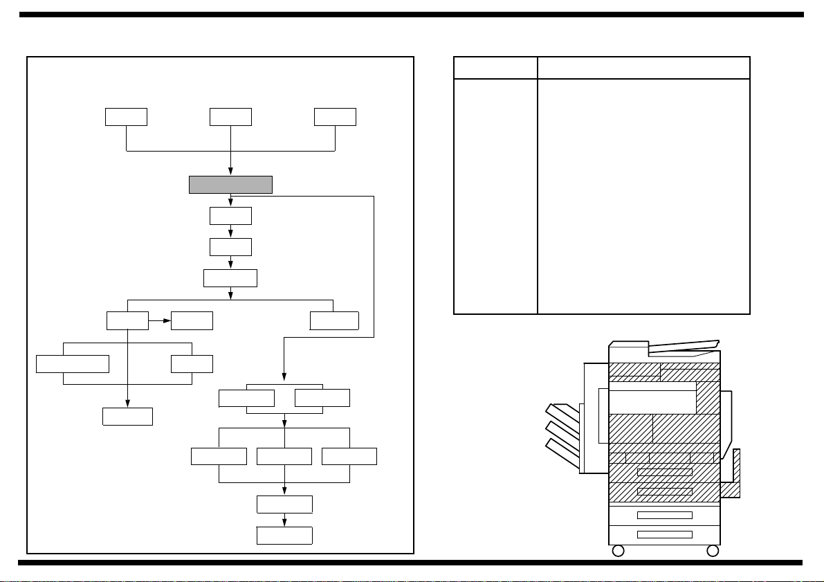
Setup Overview for
the im2020/2520/3520/2520f Copiers
PCN Description
9210 RADF
9211 Multiposition Stapling Finisher
9216
9217 9218
9212 Punch Unit
9214 Saddle Stitch Finisher
9216 Plain Stand
9217 Copy Desk (550 x 2)
9218 Large Capacity Cassette (2700 sheets)
9219 Duplex Unit
9219000000 Reversing Unit
ZC3500050 Hard Disk Drive
ZC3500060 Output Bin
ZC3500070 Job Separator
ZC3500080 Printer Controller (PCL6)
ZC3500090 Network Interface Card
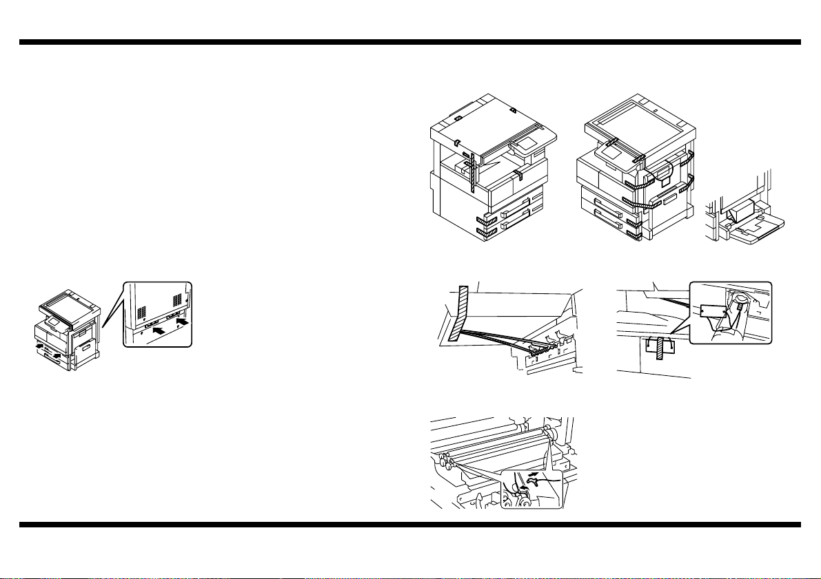
Note: When setting
up a system consisting
of the copier and options,
set up each system
component in the order
shown at right.
Copier: Printer
9210
9219
ZC3500100 Parallel Port
9219000000
ZC3500110 Network Scan Kit
ZC3500120 Internet Fax & Network Scan Kit
ZC3500130 Printer Controller (PCL6/PS3)
9212
Mailbin Finisher* 9214
ZC3500060
ZC3500080
ZC3500110
ZC3500130
ZC3500080
ZC35000709211
Memory
Note: For the details
of the setup procedure
for each option, follow
the instructions
given in the
Setup Instructions
of the corresponding
option to ensure the
option is set up
correctly.
*Not offered
ZC3500090
ZC3500050
4032-7744-02
Page 4

BLANK PAGE
Page 5

GMT (Standard Time)
GMT Atlantic Eastern Central Mountain Pacific Alaska Hawaii
-4 -5 -6 -7 -8 -9 -10
Note: Subtract an hour for Daylight Savings Time
Page 6

BLANK PAGE
Page 7

SETUP INSTRUCTIONS
9217
2-Way Paper Feed Cabinet
NOTES
• Before setting up, be sure to unplug the power cord of the machine.
• Keep all packing materials out of the reach of children.
4348-7747-02
Page 8
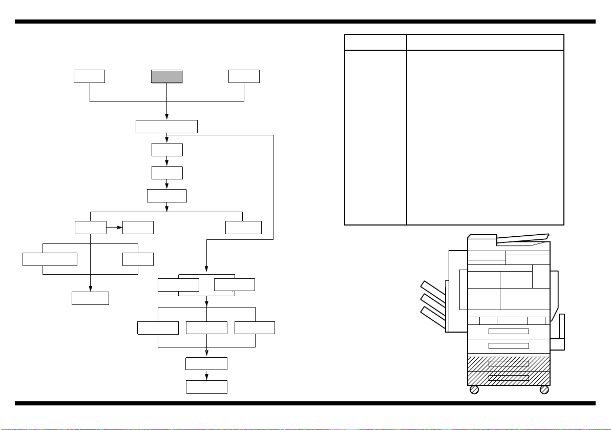
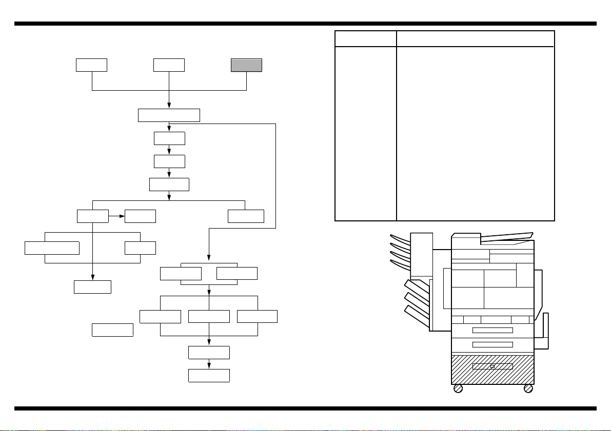
■ Setup Overview
9216
Note: When setting
up a system consisting
of the copier and options,
set up each system
component in the order
shown at right.
9212
Mailbin Finisher* 9214
ZC3500060
9217 9218
Copier: Printer
9210
9219
9219000000
ZC3500080
ZC3500110
ZC3500080
ZC35000709211
ZC3500130
Memory
9217
PCN Description
9210 RADF
9211 Multiposition Stapling Finisher
9212 Punch Unit
9214 Saddle Stitch Finisher
9216 Plain Stand
9217 Copy Desk (550 x 2)
9218 Large Capacity Cassette (2700 sheets)
9219 Duplex Unit
9219000000 Reversing Unit
ZC3500050 Hard Disk Drive
ZC3500060 Output Bin
ZC3500070 Job Separator
ZC3500080 Printer Controller (PCL6)
ZC3500090 Network Interface Card
ZC3500100 Parallel Port
ZC3500110 Network Scan Kit
ZC3500120 Internet Fax & Network Scan Kit
ZC3500130 Printer Controller (PCL6/PS3)
Note: For the de tails
of the setup procedure
for each option, follow
the instructions
given in the
Setup Instructions
of the corresponding
option to ensure the
option is set up
correctly.
*Not offered
4348-7747-02
ZC3500090
ZC3500050
– 1 –
Page 9
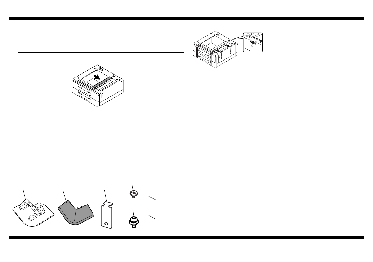
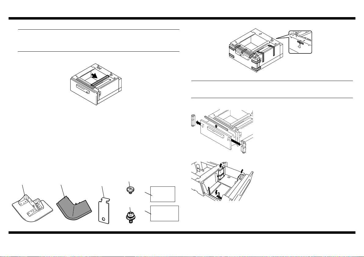
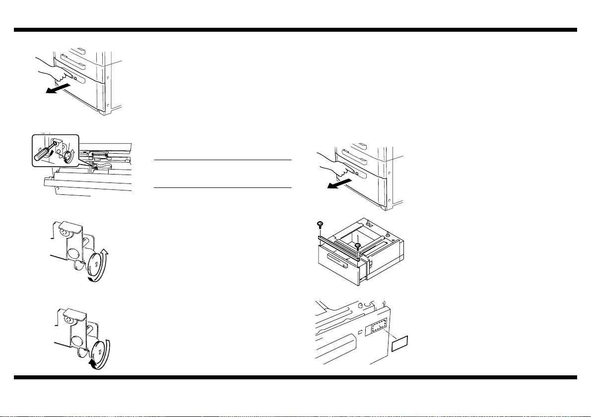
■ Unpacking
NOTE
When removing the 2 Way Paper Feed Cabinet from its shipping carton, do not hold
onto the reinforcement bracket (indicated by the arrow in the illustration below) (as a
personal injury or a deformed frame could result).
4348U004AA
1. Check that the following items are contained in the Box of Accessories.
1 Fixing Leg...............................................................................................4
2 Fixing Leg Cover ....................................................................................4
3 Fixing Bracket ........................................................................................4
4 Shoulder Screw ......................................................................................4
5 Screw (9646-0408)...............................................................................12
6 Paper Size Label ....................................................................................1
7 Setup Instructions (this manual).............................................................1
9217
2. Remove protective tape from different parts of the Paper Feed Cabinet.
4348U057AB
3. Remove the protective tape from the inside
of the drawer.
NOTE
Do not peel off the tape that fixes the Paper
Feed Cabinet hookup harness in position
until the copier is attached to the Paper
Feed Cabinet.
(1) (2)
4348U020AB
4348-7747-02
4348U099AB
(3)
4658U021AA
(4)
(7)
4658U022AA
(5)
(6)
9646040813 4348U090CA
– 2 –
Page 10
9217
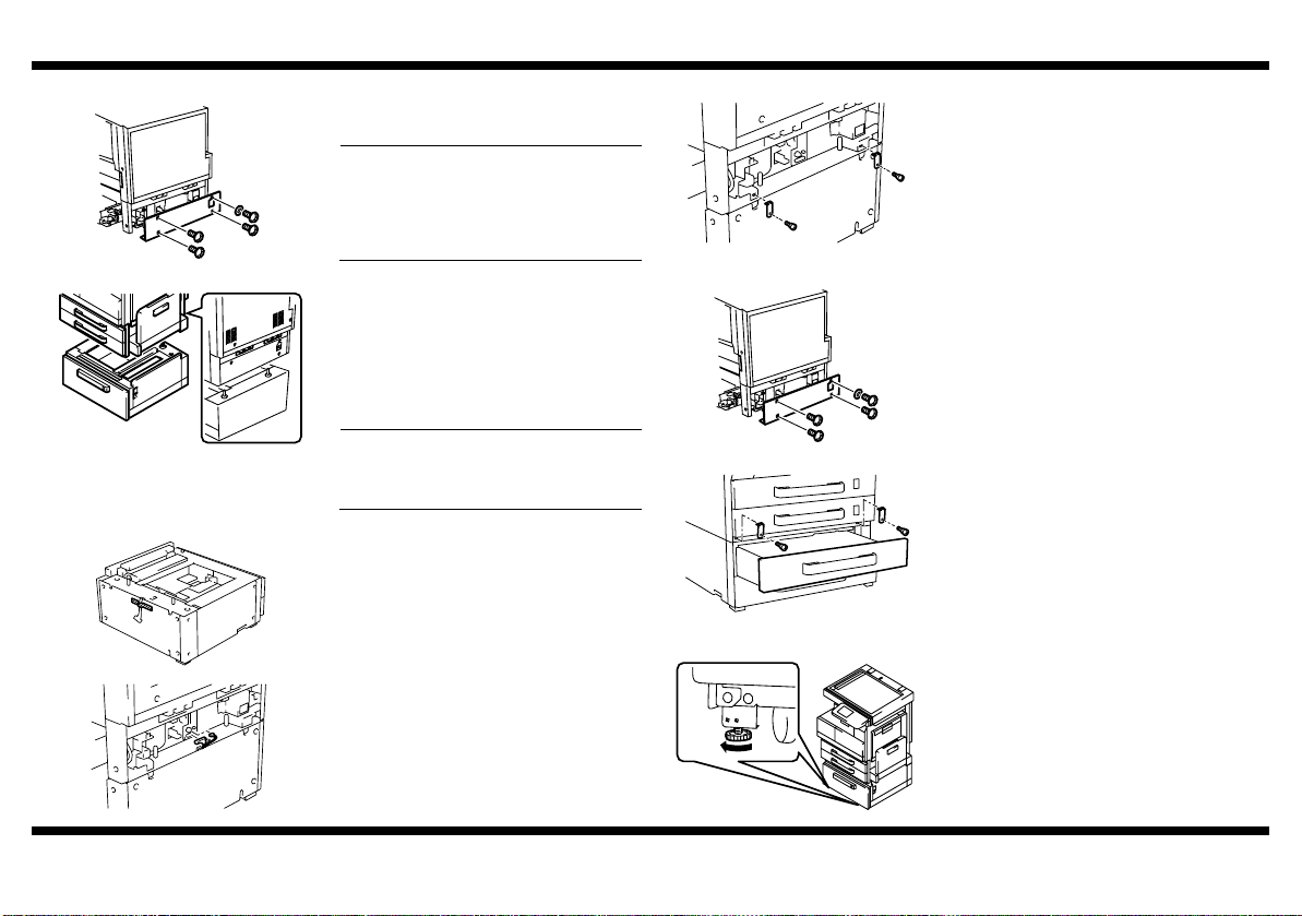
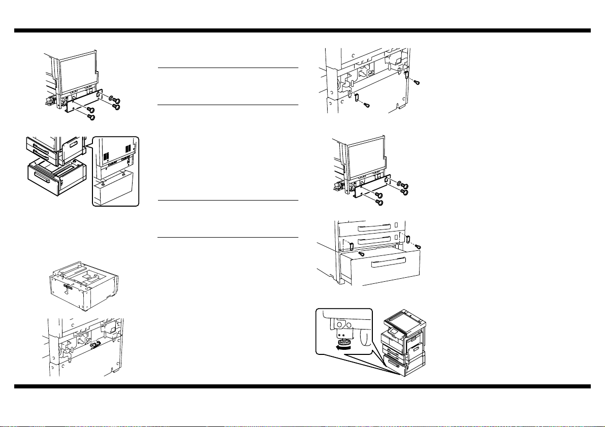
■ Attaching the Copier to the Paper Feed Cabinet
1. Remove the Lower Rear Cover of the copier
(four screws).
NOTE
Be sure to remove the Lower Rear Cover
before attempting to attach the copier to
the Paper Feed Cabinet. (This is done to
prevent the harness from getting wedged in
4348U018AC
4348U017AB
4348U005AA
mechanisms.)
2. Holding onto the transportation handles at
the front and rear of the copier, place the
copier onto the Paper Feed Cabinet. When
placing the copier, use the positioning pins in
the rear of the Paper Feed Cabinet to align
the copier correctly with the cabinet.
* Fit the rear side first.
NOTE
When attaching the copier, use care not to
apply load to the paper take-up section of
the copier.
3. Peel off the tape that fixes the Paper Feed
Cabinet hookup harness in position.
4. Connect the two connectors of the Paper
Feed Cabinet hookup harness to the copier.
5. Using the Fixing Brackets and Shoulder
Screws furnished with the Paper Feed
Cabinet, secure the copier to the Paper Feed
Cabinet (at two places in the rear).
4348U019AA
6. Reinstall the Lower Rear Cover, which has
been removed in step 1 (four screws).
4348U018AC
7. Slide out the 3rd Drawer.
8. Using the Fixing Brackets and Shoulder
Screws furnished with the Paper Feed
Cabinet, secure the copier to the Paper Feed
Cabinet (at two places at the front).
4348U051AA
■ Installing the Fixing Leg and Fixing Leg covers
1. Move the copier and Paper Feed Cabinet to
the installation site. Then, adjust the two
adjusters at the front to let the Paper Feed
Cabinet sit on the floor.
4348U006AB
4348-7747-02
4348U022AA
– 3 –
Page 11
9217
①
③
③
②
4348U023AD
4348U100AC 4348U102AB
①
①
③
③
②
4348U024AD
4348U101AC 4348U102AB
①
4348-7747-02
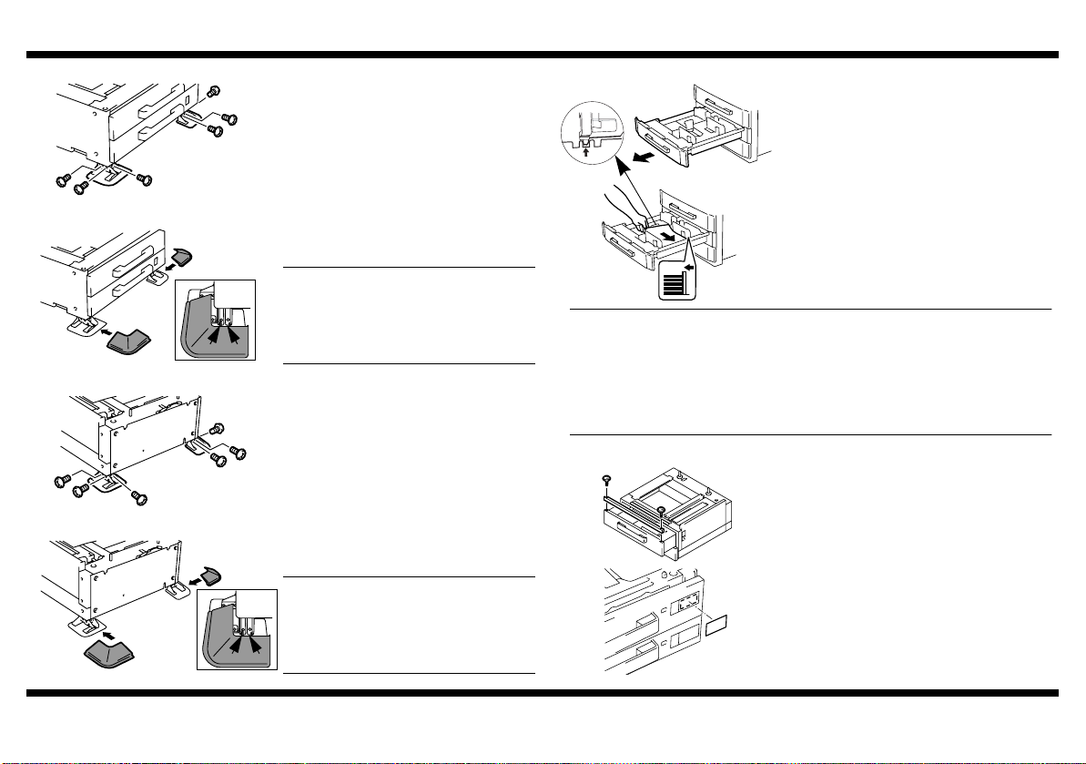
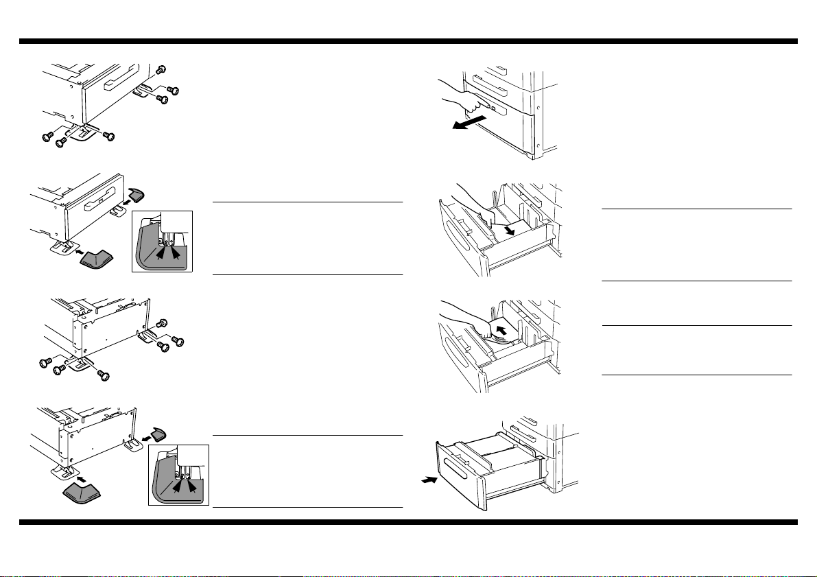
2. Install the Fixing Legs at two locations in the
front shown in the illustration. (six screws)
②
3. Install the Fixing Leg Covers at two locations
in the front shown in the illustration.
(2 Pieces)
NOTES
• Insert the Fixing Leg Covers in the direction shown by arrow until they click into
position.
• Insert the Protruded Portions of the cover
shown by the arrows into the Fixing Leg.
4. Install the Fixing Legs at two locations in the
rear shown in the illustration. (six screws)
②
5. Install the Fixing Leg Covers at two locations
in the rear shown in the illustration.
(2 Pieces)
NOTES
• Insert the Fixing Leg Covers in the direction shown by arrow until they click into
position.
• Insert the Protruded Portions of the cover
shown by the arrows into the Fixing Leg.
■ Loading Paper
1. Slide out the 3rd and 4th Drawer.
4348U095AA
4348U048AA
2. Load the paper stack so that it rests below
the tab fitted to the Edge Guide.
4348U091AA
NOTES
• Make sure that the top level of the paper stack does not exceed the
paper level indicator.
• Slide the Edge Guide tightly up against the edge of the paper stack so that there is
no gap between them.
• With the Trailing Edge Stop, fit its locking tab properly into the slit at the correct
paper size position.
• Correct any curl in the paper before loading.
■ Installing the Ornamental Cover
1. Install the Ornamental Cover attached to the
copier (two screws).
4348U049AA
2. Slide the drawer back in.
3. Affix the Paper Size Label furnished with the
Paper Feed Cabinet to the location shown in
the illustration. (The size label is similarly put
on the 4th.)
4348U052AA
– 4 –
▼
(MAX)
Page 12
9217
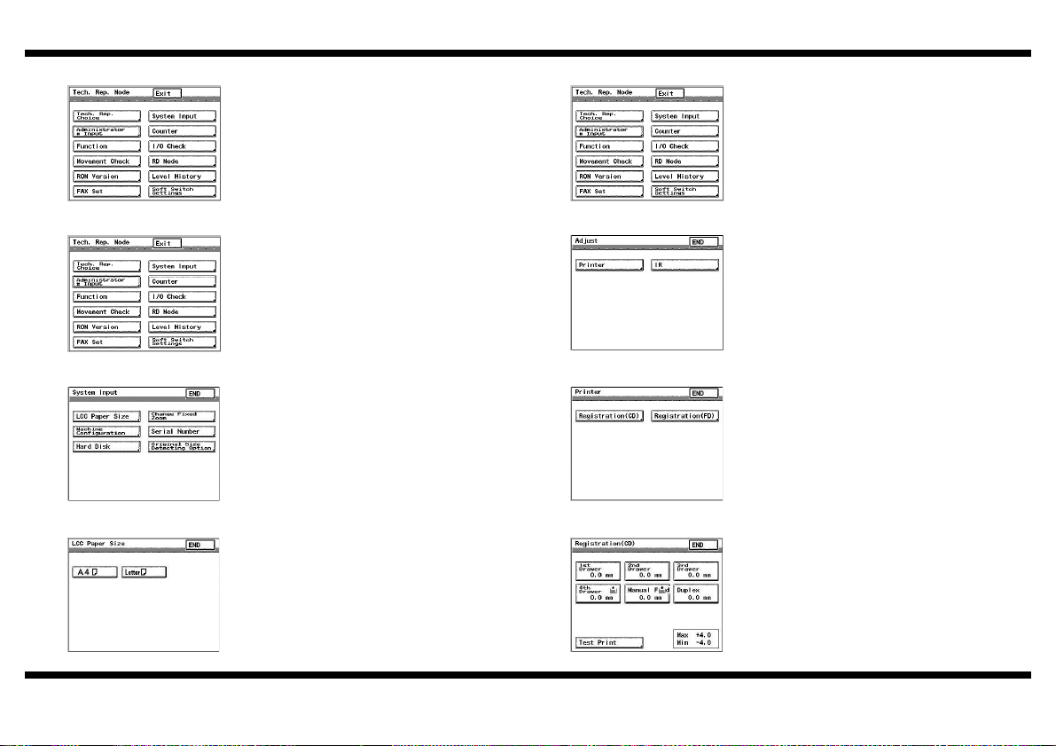
■ Checking the Paper Reference Position
1. Turn ON the copier.
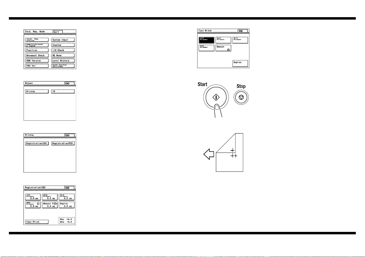
2. Call the Tech. Rep. Mode to the screen.
* See the Service Manual for the procedure.
4348P005CB
3. Follow these steps to call the Adjust mode to
the screen.
* With the Tech. Rep. Mode displayed on the
screen, press the Stop key and then Start
key, in that order.
4. Touch “Printer” to call up the Printer screen.
4348P003CA
5. Touch “Registration (CD)” to display the
Registration (CD) screen.
4348P009CA
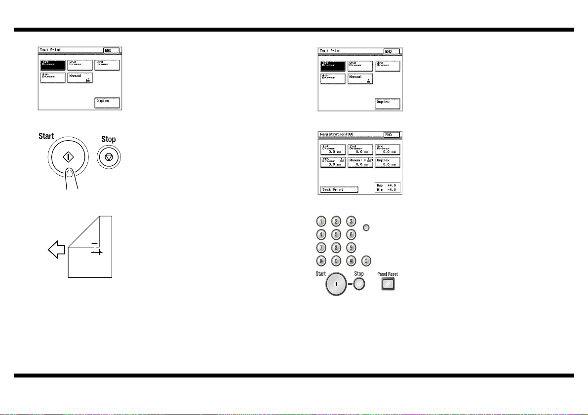
6. Touch “Test Print” to display the Test Print
screen.
4348P015CA
4348-7747-02
– 5 –
4348P017CA
4002O280CB
4348U054AA
7. Touch “3rd Drawer.” (This highlights the “3rd
Drawer” key.)
8. Press the Start key on the control panel.
(The copier will produce an output of a test
print.)
9. Measure width A on the test print and check
to see if the measured dimension falls within
the specified range.
A
<Specifications: 10 ± 2.0 mm>
10. If the measured width A falls within the
specified range, press the Panel Reset key
to recall the Basic screen.
* Do the same procedure for the 4th that for
3th drawer.
11. If the measured width A falls outside the
specified range, perform the following
procedure to adjust the paper reference
position.
Page 13
9217
■ Adjusting the Paper Reference Position ■ Adjusting the Paper Reference Position (2)
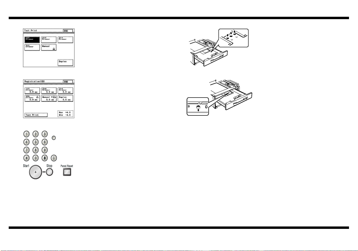
1. Touch “END” on the Test Print screen.
1. Slide out the drawer and unload paper from
it.
2. Loosen the three screws at the center of the
Paper Lifting Plate.
4348P017CA
4348P015CA
4348U093CA
4348-7747-02
2. Select “3rd or 4th Drawer” on the
Registration (CD) screen.
(This highlights the “3rd or 4th Drawer” key.)
3. Press the Clear (C) key and, using the 10Key Pad, change the setting value as
detailed below.
• If width A is greater than the specified value
(e.g. +1.0 mm), enter -1.0.
• If width A is smaller than the specified value
(e.g. -1.0 mm), enter +1.0.
* Press the “✽” key to select either + or -.
* If the Adjust mode is not effective enough to
make the adjustment, perform the following
procedure [paper reference position adjustment (2)].
– 6 –
4348U008AB
4348U009AA
3. Watching the graduations provided in the
drawer, move the Edge Guide in the rear.
• If width A is greater than the specified value,
move the Edge Guide toward the front.
• If width A is smaller than the specified value,
move the Edge Guide toward the rear.
4. Load paper and let the copier produce
another test print. Then, check width A.
* Make the adjustment until width A falls within
the specified range.
5. Press the Panel Reset key to recall the Tech.
Rep. Mode to the screen. Then, touch “Exit”
on the Tech. Rep. Mode screen.
Page 14

BLANK PAGE
Page 15

SETUP INSTRUCTIONS
9218
Large Capacity Cabinet
NOTES
• Before setting up, be sure to unplug the power cord of the machine.
• Keep all packing materials out of the reach of children.
4348-7743-03
Page 16
9218
■ Setup Overview
9216
Note: When setting
up a system consisting
of the copier and options,
set up each system
component in the order
shown at right.
Mailbin Finisher* 9214
ZC3500060
ZC3500050
Copier: Printer
9219000000
9212
ZC3500110
9217
9210
9219
ZC3500080
ZC3500130
ZC3500080
ZC3500090
PCN Description
9210 RADF
9218
9211 Multiposition Stapling Finisher
9212 Punch Unit
9214 Saddle Stitch Finisher
9216 Plain Stand
9217 Copy Desk (550 x 2)
9218 Large Capacity Cassette (2700 sheets)
9219 Duplex Unit
9219000000 Reversing Unit
ZC3500050 Hard Disk Drive
ZC3500060 Output Bin
ZC3500070 Job Separator
ZC3500080 Printer Controller (PCL6)
ZC3500090 Network Interface Card
ZC3500100 Parallel Port
ZC3500110 Network Scan Kit
ZC3500120 Internet Fax & Network Scan Kit
ZC35000709211
Memory
ZC3500130 Printer Controller (PCL6/PS3)
Note: For the details
of the setup procedure
for each option, follow
the instructions
given in the
Setup Instructions
of the corresponding
option to ensure the
option is set up
correctly.
*Not offered
4348-7743-03
ZC3500050
– 1 –
4348U094AA
Page 17
■ Unpacking
NOTE
When removing the Large Capacity Cabinet from its shipping carton, do not hold
onto the reinforcement bracket (indicated by the arrow in the illustration below) (as a
personal injury or a deformed frame could result).
9218
2. Remove protective tape from the Large Capacity Cabinet.
4348U015AC
NOTE
Do not peel off the tape that fixes the Large Capacity Cabinet hookup harness in
position until the copier is attached to the Large Capacity Cabinet.
4348U016AA
1. Check that the following items are contained in the Box of Accessories.
1 Fixing Leg...............................................................................................4
2 Fixing Leg Cover ....................................................................................4
3 Fixing Bracket ........................................................................................4
4 Shoulder Screw ......................................................................................4
5 Screw (9646-0408)...............................................................................12
6 Paper Size Label ....................................................................................1
7 Setup Instructions (this manual).............................................................1
(1) (2)
(3)
(4)
(7)
4658U022AA
(5)
(6)
4348U020AB
4348U099AB
4658U021AA
9646040813 4348U090CA
4348-7743-03
3. Remove protective material from Large
Capacity Cabinet.
4348U104AA
4. Remove the shipping preservatives and
protective tape from the inside of the drawer.
5. Slide the drawer back in.
4348U003AB
– 2 –
Page 18
9218
■ Attaching the Copier to the Large Capacity Cabinet
1. Remove the Lower Rear Cover of the copier
(four screws).
NOTE
Be sure to remove the Lower Rear Cover
before attempting to attach the copier to
the Large Capacity Cabinet.
4348U018AC
2. Holding onto the transportation handles at
the front and rear of the copier, place the
copier onto the Large Capacity Cabinet.
When placing the copier, use the positioning
pins in the rear of the Large Capacity Cabinet
to align the copier correctly with the cabinet.
* Fit the rear side first.
4348U017AB
4348U005AA
NOTE
When attaching the copier, use care not to
apply load to the paper take-up section of
the copier.
3. Peel off the tape that fixes the Large
Capacity Cabinet hookup harness in
position.
4. Connect the two connectors of the Large
Capacity Cabinet hookup harness to the
copier.
5. Using the Fixing Brackets and Shoulder
Screws furnished with the Large Capacity
Cabinet, secure the copier to the Large
Capacity Cabinet (at two places in the rear).
4348U019AA
6. Reinstall the Lower Rear Cover, which has
been removed in step 1 (four screws).
4348U018AC
7. Using the Fixing Brackets and Shoulder
Screws furnished with the Large Capacity
Cabinet, secure the copier to the Large
Capacity Cabinet (at two places at the front).
4348U021AA
■ Installing the Fixing Leg and Fixing Leg covers
1. Move the copier and Large Capacity Cabinet
to the installation site. Then, adjust the two
adjusters at the front to let the Large
Capacity Cabinet sit on the floor.
4348U006AB
4348-7743-03
4348U022AA
– 3 –
Page 19
9218
①
③
③
②
4348U098AA
4348U103AA 4348U102AB
①
①
③
③
②
4348U024AD
4348U101AC 4348U102AB
①
4348-7743-03
2. Install the Fixing Legs at two locations in the
front shown in the illustration. (six screws)
②
3. Install the Fixing Leg Covers at two locations
in the front shown in the illustration.
(2 Pieces)
NOTES
• Insert the Fixing Leg Covers in the direction shown by arrow until they click into
position.
• Insert the Protruded Portions of the cover
shown by the arrows into the Fixing Leg.
4. Install the Fixing Legs at two locations in the
rear shown in the illustration. (six screws)
②
5. Install the Fixing Leg Covers at two locations
in the rear shown in the illustration.
(2 Pieces)
NOTES
• Insert the Fixing Leg Covers in the direction shown by arrow until they click into
position.
• Insert the Protruded Portions of the cover
shown by the arrows into the Fixing Leg.
■ Loading Paper
4348U010AA
4348U012AA
4348U014AA
4348U013AA
– 4 –
1. Press the Paper Descent button and then
slide out the drawer from the Large Capacity
Cabinet.
2. Align the edges of the paper stack and place
the stack into the drawer.
NOTES
• Make sure that the top level of the paper
▼
stack does not exceed the
paper level indicator.
(MAX)
• Correct any curl in the paper before loading.
3. Align the edges of the paper stack and place
the stack into the drawer.
NOTE
Make sure that the top level of the paper
▼
stack does not exceed the
level indicator.
(MAX) paper
4. Slide the drawer back into the cabinet.
Page 20
9218
■ Making Settings for Paper Size ■ Checking the Paper Reference Position
1. Call the Tech. Rep. Mode to the screen.
(See the Service Manual for the procedure.)
1. Call the Tech. Rep. Mode to the screen.
(See the Service Manual for the procedure.)
4348P005CB
4348P005CB
4348P007CA
4348P013CA
4348-7743-03
2. Touch “System Input” to call up the System
Input screen.
3. Touch “LCC Paper Size” to display the LCC
Paper Size screen.
4. Touch “A4” paper size key.
(This highlights the “A4” paper size key.)
5. Touch “END” on the LCC Paper Size screen.
4348P005CB
2. Follow these steps to call the Adjust mode to
the screen.
* With the Tech. Rep. Mode displayed on the
screen, press the Stop key and then Start
key, in that order.
3. Touch “Printer” to call up the Printer screen.
4348P003CA
4. Touch “Registration (CD)” to display the
Registration (CD) screen.
4348P009CA
5. Touch “Test Print” to display the Test Print
screen.
4348P015CA
– 5 –
Page 21
9218
4348P017CA
4002O280CB
4348U054AA
6. Touch “3rd Drawer.” (This highlights the “3rd
Drawer” key.)
4348P017CA
7. Press the Start key on the control panel.
(The copier will produce an output of a test
print.)
4348P015CA
8. Measure width A on the test print and check
to see if the measured dimension falls within
the specified range.
A
<Specifications: 10 ± 2.0 mm>
9. If the measured width A falls within the
4348U093CA
specified range, press the Panel Reset key
to recall the Basic screen.
1. Touch “END” on the Test Print screen.
2. Select “3rd Drawer” on the Registration (CD)
screen. (This highlights the “3rd Drawer”
key.)
3. Press the Clear (C) key and, using the 10Key Pad, change the setting value as
detailed below.
• If width A is greater than the specified value
(e.g. +1.0 mm), enter -1.0.
• If width A is smaller than the specified value
(e.g. -1.0 mm), enter +1.0.
* Press the “✽” key to select either + or -.
■ Adjusting the Paper Reference Position
4348-7743-03
10. If the measured width A falls outside the
specified range, perform the following
procedure to adjust the paper reference
position.
– 6 –
Page 22
9218
■ Adjusting the Paper Reference Position (2)
1. Press the Paper Descent button and then
slide out the drawer from the Large Capacity
Cabinet.
4348U010AA
2. Open the Right Door.
3. Loosen the adjusting screw and turn screw D
clockwise or counterclockwise as necessary.
NOTE
Use care not to damage or dent the paper
path surface inside the Right Door.
4348U011AA
• If width A is greater than the specified value,
turn screw D counterclockwise.
4002U106AA
• If width A is smaller than the specified value,
turn screw D clockwise.
4. Let the copier produce another test print and
check for the good paper reference position.
5. Make the adjustment until the specified
reference position is achieved.
6. Press the Panel Reset key to recall the Tech.
Rep. Mode to the screen.
7. Touch “Exit” on the Tech. Rep. Mode screen
to go back to the initial screen
■ Installing the Ornamental Cover
1. Press the Paper Descent button and then
slide out the drawer from the Large Capacity
Cabinet.
4348U010AA
2. Install the Ornamental Cover attached to the
copier (two screws).
3. Slide the drawer back in.
4348U050AA
■ Affixing the Paper Size Label
1. Affix the Paper Size Label furnished with the
Large Capacity Cabinet to the location
shown in the illustration.
4002U105AA
4348-7743-03
4348U007AA
– 7 –
Page 23

SETUP INSTRUCTIONS
im2020/im2520/im3520
Copiers
NOTES
• Keep all packing materials out of the reach of children.
• Before setting up, be sure to unplug the power cord of the machine.
4030-7744-02
Page 24

Setup Overview
■
Note: When setting
up a system consisting
of the copier and options,
set up each system
component in the order
shown at right.
Mailbin Finisher* 9214
9216
ZC3500060
9217 9218
Copier: Printer
9210
9219
9219000000
9212
ZC3500080
ZC3500110
ZC3500080
ZC3500090
ZC35000709211
ZC3500130
Memory
im2020/im2520/im3520
PCN Description
9210 RADF
9211 Multiposition Stapling Finisher
9212 Punch Unit
9214 Saddle Stitch Finisher
9216 Plain Stand
9217 Copy Desk (550 x 2)
9218 Large Capacity Cassette (2700 sheets)
9219 Duplex Unit
9219000000 Reversing Unit
ZC3500050 Hard Disk Drive
ZC3500060 Output Bin
ZC3500070 Job Separator
ZC3500080 Printer Controller (PCL6)
ZC3500090 Network Interface Card
ZC3500100 Parallel Port
ZC3500110 Network Scan Kit
ZC3500120 Internet Fax & Network Scan Kit
ZC3500130 Printer Controller (PCL6/PS3)
Note: For the details
of the setup procedure
for each option, follow
the instructions
given in the
Setup Instructions
of the corresponding
option to ensure the
option is set up
correctly.
*Not offered
4030-7744-02
ZC3500050
– 1 –
4030U029AA
Page 25
im2020/im2520/im3520
■ Unpacking
• Check that the following items are contained in the Box of Accessories.
2 User Manual (Advanced Operations).....................................................1
3 Setup Instructions (this manual).............................................................1
4 Ornamental Cover ..................................................................................1
5 Ornamental Cover Mounting Screw .......................................................2
6 Operator’s Manual Holder......................................................................1
7 Power Cord ............................................................................................1
8 Tray Label ..............................................................................................1
9 Scanner Lock Lever Seal .......................................................................1
* The Ornamental Cover and Ornamental Cover Mounting Screw are used
when a paper source option is mounted. (See the Setup Instructions for
the corresponding paper source option.)
■ Removing Copier from Packaging Box
1. Unpack the packaging box and remove
cushioning materials and vinyl bags from the
box.
2. Hold onto the portions indicated in the
illustration on the left with two persons.
While keeping the copier level, take it out
4030U068CA
from the box.
■ Removing Protective Tape and Packaging Materials and Unlocking Scanner
1. Remove pieces of protective tape and packaging materials.1 User Manual (Basic Operations)............................................................1
4030U002AA 4030U069CA
4030U027AA 4030U028AA
2. Open the Right Door and remove the
protective tape.
4030-7744-02
3. Push the lever in the direction of the arrow
and remove the spacer from the Transfer
Roller.
4030U004AA
– 2 –
Page 26
im2020/im2520/im3520
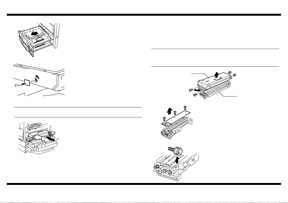
4. Slide out the drawer and remove the
protective tape.
4030U030AA
5. Turn the Scanner Lock Lever to unlock the
Scanner.
6. Affix the Scanner Lock Lever Seal.
4030U031AB
■ Loading the Starter
NOTE
The starter is not shipped with the copier. Purchase one that is separately available.
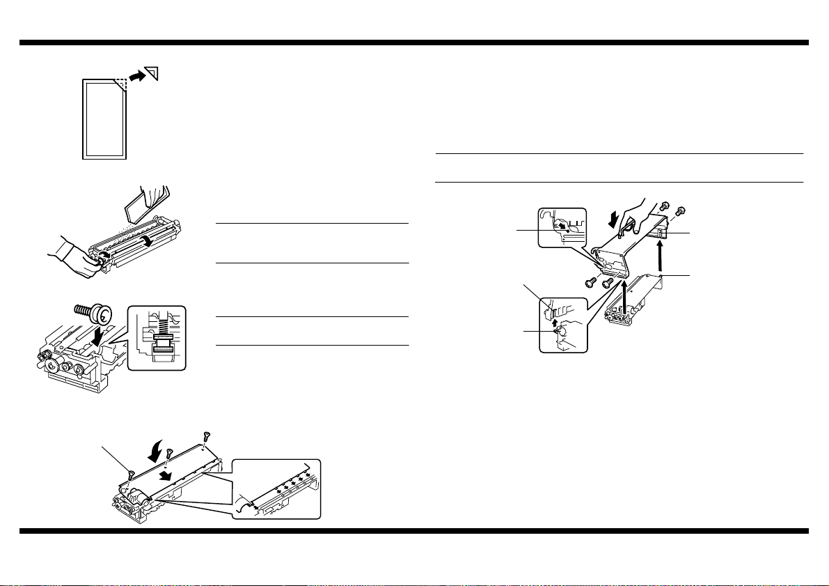
1. Open the Right Door and remove the
Imaging Unit (IU).
4030U006AB
2. Remove screws that secure the PC Drum Unit in position (two each on the right and
left).
* Silver screws found on the lower part of the PC Drum Unit
3. Slightly opening the lower part (the shadowed portion) on both sides of the PC Drum
Unit, take out the PC Drum Unit.
NOTE
Do not touch or scratch the PC Drum.
Cover the PC Drum Unit, which has been removed, with a protective cloth or similar
tool.
PC Drum Unit
4030U007AC
Developing Unit
4. Remove the Developing Unit Cover (three
screws).
4030U010AA
5. Remove the Toner Supply Port.
4030-7744-02
4030U011AA
– 3 –
Page 27
im2020/im2520/im3520
6. Ready a packet of starter and cut off one
corner of the aluminum packet with scissors.
4030U012AA
7. While turning the gear in the direction of the
arrow, pour the packet of starter evenly into
the Developer Chamber.
NOTE
Turn the Magnet Roller in the direction of its
normal rotation, and not the backward.
4030U013AB
8. Reinstall the Toner Supply Port.
NOTE
Make sure of the correct mounting position.
4030U014AB
9. Reinstall the Developing Unit Cover, ensuring that its tabs are fitted properly into the
slits (three screws).
Tighten this screw first
10. Align the shaft of the Developing Unit with the inner guide of the PC Drum Unit.
11. Slide the PC Drum Unit along the guide to check that the positioning pin is properly
aligned with the mating hole.
12. Screw the PC Drum Unit in position (two silver screws each on the right and left
sides).
NOTE
Use care not to touch or scratch the PC Drum.
Positioning Pin
Guide
Guide
Shaft
Shaft
4030U016AD
4030U015AC
4030-7744-02
– 4 –
Page 28
im2020/im2520/im3520
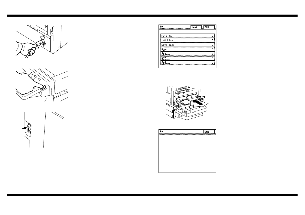
■ Plugging in Power Cord and Turning Power ON ■ Clearing the Counters
1. Plug in the power cord to the copier.
2. Connect the power cord to a power outlet.
4030U021AA
3. Turn ON the Subswitch located on the side of
4030P007CA
the control panel.
■ ATDC Adjustment
4030U023AA
4. Turn ON the Power Switch located on the left
side in the rear.
4030U017AB
1. Call the Tech. Rep. Mode to the screen. (For
the procedure, see the Service Manual.)
2. Select functions in this order: Tech. Rep.
Mode → Counter → PM.
3. Using the Clear key, clear “PC Life” and then
“IC Life.”
4. Touch “END.”
5. Press the Panel Reset key.
1. Install the Imaging Unit (IU) in position.
2. Close the Right Door.
3. Select functions in this order: Tech. Rep.
Mode → Function → F8.
4030U022AA
4030-7744-02
– 5 –
4030P002CA
4. Press the Start key to run an F8 operation.
(At this time, the Start key changes to
orange.)
5. When the Start key changes to green, touch
“END.”
6. Press the Panel Reset key.
7. Touch “Exit.”
Page 29
im2020/im2520/im3520
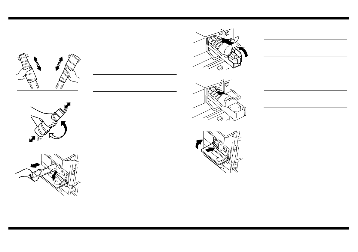
■ Installing the Toner Bottle
NOTE
The Toner Bottle is not shipped with the copier. Purchase one that is separately
available.
1. From a height of about 10 cm, tap the Toner
Bottle against a table or other hard object
four to five times. Then turn it upside down
and repeat the same procedure.
NOTE
Toner can be caked in the Toner Bottle. Be
1166O228AA
1166O095AA
4030U018AA
sure to perform this procedure.
2. Shake the Toner Bottle well about five times
in the vertical direction. Then, turn it over
and repeat the same procedure.
3. Open the Front Door and slide the Toner
Hopper out of the copier.
4030U019AB
4030U032AA
4030U020AA
4. Open the Toner Holder and mount the Toner
Bottle.
NOTE
Place the Toner Bottle so that its seal
surface faces upward.
5. Close the Toner Holder.
6. Gently peel off the seal toward you from the
bottle.
NOTE
Perform this procedure slowly, as toner can
burst out when the seal is peeled off.
7. Slide the Toner Hopper back into the copier
until it clicks into position. Then, close the
Front Door.
4030-7744-02
– 6 –
Page 30
im2020/im2520/im3520
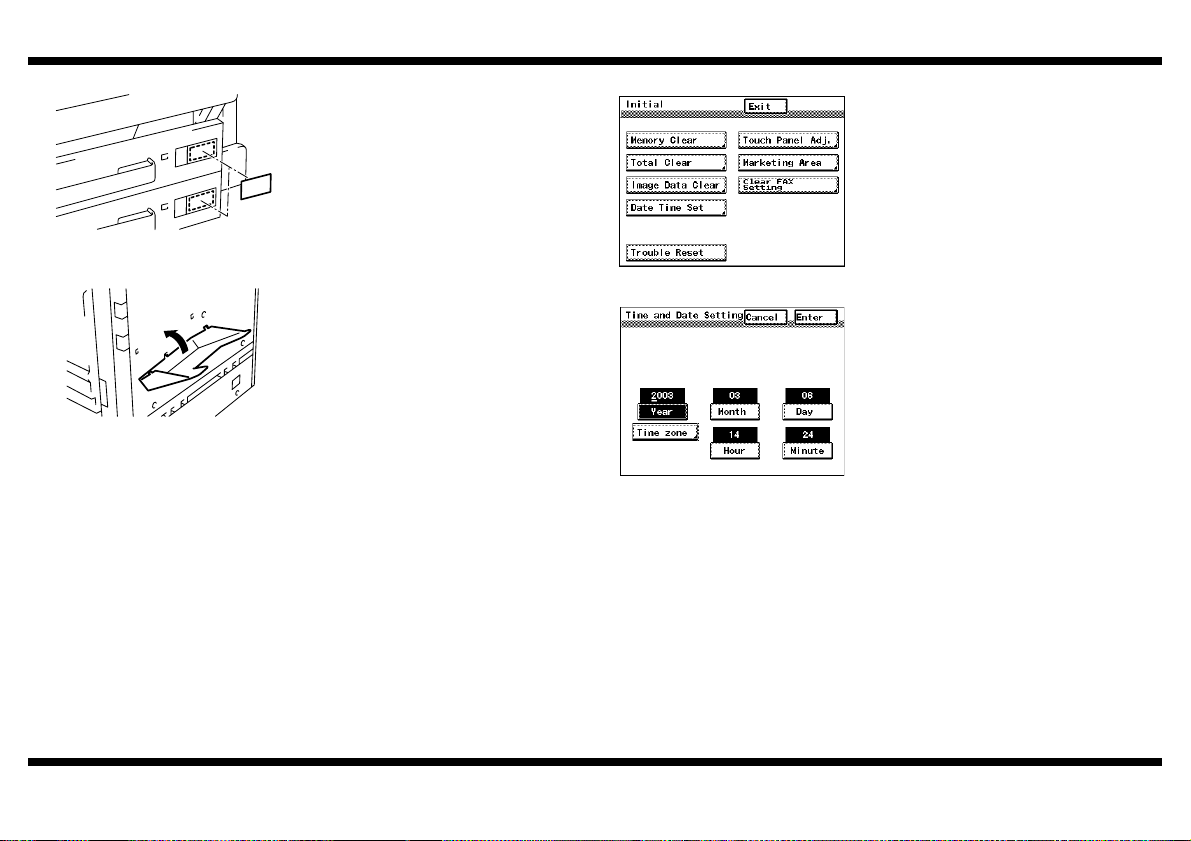
■ Affixing the Tray Label
1. Affix the Tray Label to the 1st and 2nd
Drawers.
2. Load the drawers with paper.
4030U025AB
■ Attaching the Operator’s Manual Holder
1. Attach the Operator’s Manual Holder to the
back surface of the copier.
4030U024AA
■ Setting Time-of-Day and Date
4030P003CA
4030P011CA
1. Call the Initial Mode to the screen. (For the
procedure, see the Service Manual.)
2. Select “Date Time Set.”
3. Enter the date and time-of-day from the 10Key Pad.
4. Select “Time Zone.”
5. Enter the time zone from the 10-Key Pad.
6. Touch “Enter.”
7. Touch “Exit.”
4030-7744-02
– 7 –
Page 31

■ Installing the Original Cover Kit
• Check that the following items are contained.
1 Original Cover ........................................................................................1
2 Hinge Cover (Right) ...............................................................................1
3 Hinge Cover (Left)..................................................................................1
4 Document Scanning Glass Cover..........................................................1
5 Screw .....................................................................................................5
1 2 3
4599U001AA
4 5
4599U002AA 4599U003AA
im2020/im2520/im3520
1. Remove the Rear Upper Cover and Hinge
Covers (three screws).
4599U005AB
2. Install the Hinge Covers (Right and Left)
included in the kit (five screws).
3. Reinstall the Rear Upper Cover (three
screws).
4599U006AA
4. Install the Original Cover.
5. Peel off the double-sided adhesive tape from
the Document Scanning Glass Cover. Then,
affix the Document Scanning Glass Cover to
the position shown in the illustration.
4030-7744-02
4599U004AA
9654
4599U007AB
– 8 –
Page 32

BLANK PAGE
Page 33

SETUP INSTRUCTIONS
im2520f Copier
NOTES
• Keep all packing materials out of the reach of children.
• Before setting up, be sure to unplug the power cord of the machine.
4032-7744-02
Page 34

■Setup Overview
Note: When setting
up a system consisting
of the copier and options,
set up each system
component in the order
shown at right.
Mailbin Finisher* 9214
9216
9212
9217 9218
Copier: Printer
9210
9219
9219000000
im2520f
PCN Description
9210 RADF
9211 Multiposition Stapling Finisher
9212 Punch Unit
9214 Saddle Stitch Finisher
9216 Plain Stand
9217 Copy Desk (550 x 2)
9218 Large Capacity Cassette (2700 sheets)
9219 Duplex Unit
9219000000 Reversing Unit
ZC3500050 Hard Disk Drive
ZC3500060 Output Bin
ZC3500070 Job Separator
ZC3500080 Printer Controller (PCL6)
ZC3500090 Network Interface Card
ZC3500100 Parallel Port
ZC3500110 Network Scan Kit
ZC3500120 Internet Fax & Network Scan Kit
ZC35000709211
ZC3500130 Printer Controller (PCL6/PS3)
*Not offered
4032-7744-02
ZC3500060
ZC3500080
ZC3500110
ZC3500130
ZC3500080
ZC3500090
ZC3500050
Note: For the details
of the setup procedure
for each option, follow
the instructions
Memory
– 1 –
given in the
Setup Instructions
of the corresponding
option to ensure the
option is set up
correctly.
4030U029AA
Page 35

im2520f
■ Unpacking
Check that the following items are contained in the Box of Accessories.
•
2 User Manual (Advanced Operations).....................................................1
3 User Manual (Fax Operations) ...............................................................1
4 Setup Instructions (this manual).............................................................1
5 Ornamental Cover..................................................................................1
6 Ornamental Cover Mounting Screw .......................................................2
7 Operator’s Manual Holder ......................................................................1
8 Power Cord ............................................................................................1
9 Tray Label ..............................................................................................1
10 Scanner Lock Lever Seal .......................................................................1
11 Warranty Card (U.S.A. areas only).........................................................1
12 Telephone Cable ....................................................................................1
* The Ornamental Cover and Ornamental Cover Mounting Screw are used
when a paper source option is mounted. (See the Setup Instructions for
the corresponding paper source option.)
■ Removing Copier from Packaging Box
1. Unpack the packaging box and remove
cushioning materials and vinyl bags from the
box.
2. Hold onto the portions indicated in the
illustration on the left with two persons.
While keeping the copier level, take it out
4030U068CA
from the box.
■ Removing Protective Tape and Packaging Materials and Unlocking Scanner
1. Remove pieces of protective tape and packaging materials.1 User Manual (Basic Operations) ............................................................1
4030U002AA 4030U069CA
4030U027AA 4030U028AA
2. Open the Right Door and remove the
protective tape.
4032-7744-02
3. Push the lever in the direction of the arrow
and remove the spacer from the Transfer
Roller.
4030U004AA
– 2 –
Page 36

im2520f
4. Slide out the drawer and remove the
protective tape.
4030U030AA
5. Turn the Scanner Lock Lever to unlock the
Scanner.
6. Affix the Scanner Lock Lever Seal.
4030U031AB
■ Loading the Starter
NOTE
The starter is not shipped with the copier. Purchase one that is separately available.
1. Open the Right Door and remove the
Imaging Unit (IU).
4030U006AB
2. Remove screws that secure the PC Drum Unit in position (two each on the right and
left).
* Silver screws found on the lower part of the PC Drum Unit
3. Slightly opening the lower part (the shadowed portion) on both sides of the PC Drum
Unit, take out the PC Drum Unit.
NOTE
Do not touch or scratch the PC Drum.
Cover the PC Drum Unit, which has been removed, with a protective cloth or similar
tool.
PC Drum Unit
4030U007AC
Developing Unit
4. Remove the Developing Unit Cover (three
screws).
4030U010AA
5. Remove the Toner Supply Port.
4032-7744-02
4030U011AA
– 3 –
Page 37

im2520f
6. Ready a packet of starter and cut off one
corner of the aluminum packet with scissors.
4030U012AA
7. While turning the gear in the direction of the
arrow, pour the packet of starter evenly into
the Developer Chamber.
NOTE
Turn the Magnet Roller in the direction of its
normal rotation, and not the backward.
4030U013AB
8. Reinstall the Toner Supply Port.
NOTE
Make sure of the correct mounting position.
4030U014AB
9. Reinstall the Developing Unit Cover, ensuring that its tabs are fitted properly into the
slits (three screws).
Tighten this screw first
10. Align the shaft of the Developing Unit with the inner guide of the PC Drum Unit.
11. Slide the PC Drum Unit along the guide to check that the positioning pin is properly
aligned with the mating hole.
12. Screw the PC Drum Unit in position (two silver screws each on the right and left
sides).
NOTE
Use care not to touch or scratch the PC Drum.
Positioning Pin
Guide
Guide
Shaft
Shaft
4030U016AD
4030U015AC
4032-7744-02
– 4 –
Page 38

im2520f
■ Plugging in Power Cord and Turning Power ON ■ Clearing the Counters
1. Plug in the power cord to the copier.
2. Connect the power cord to a power outlet.
4030U021AA
3. Turn ON the Subswitch located on the side of
4030P007CA
■ ATDC Adjustment
4030U023AA
4. Turn ON the Power Switch located on the left
side in the rear.
4030U017AB
1. Call the Tech. Rep. Mode to the screen. (For
the procedure, see the Service Manual.)
2. Select functions in this order: Tech. Rep.
Mode → Counter → PM.
3. Using the Clear key, clear “PC Life,” “IC Life”
and then “Developer.”
4. Touch “END.”
5. Press the Panel Reset key.
1. Install the Imaging Unit (IU) in position.
2. Close the Right Door.
3. Select functions in this order: Tech. Rep.
Mode → Function → F8.
4030U022AA
4032-7744-02
– 5 –
4030P002CA
4. Press the Start key to run an F8 operation.
(At this time, the Start key changes to
orange.)
5. When the Start key changes to green, touch
“END.”
6. Press the Panel Reset key.
7. Touch “Exit.”
Page 39

im2520f
NOTE
NOTE
■ Installing the Toner Bottle
NOTE
The Toner Bottle is not shipped with the copier. Purchase one that is separately
available.
1. From a height of about 10 cm, tap the Toner
Bottle against a table or other hard object
four to five times. Then turn it upside down
and repeat the same procedure.
NOTE
Toner can be caked in the Toner Bottle. Be
sure to perform this procedure.
1166O228AA
2. Shake the Toner Bottle well about five times
in the vertical direction. Then, turn it over
and repeat the same procedure.
1166O095AA
3. Open the Front Door and slide the Toner
Hopper out of the copier.
4030U018AA
4. Open the Toner Holder and mount the Toner
Bottle.
Place the Toner Bottle so that its seal
surface faces upward.
5. Close the Toner Holder.
4030U019AB
6. Gently peel off the seal toward you from the
bottle.
Perform this procedure slowly, as toner can
burst out when the seal is peeled off.
4030U032AA
7. Slide the Toner Hopper back into the copier
until it clicks into position. Then, close the
Front Door.
4030U020AA
4032-7744-02
– 6 –
Page 40

im2520f
)
■ Affixing the Tray Label
1. Affix the Tray Label to the 1st and 2nd
Drawers.
2. Load the drawers with paper.
4030U025AB
■ Attaching the Operator’s Manual Holder
1. Attach the Operator’s Manual Holder to the
back surface of the copier.
4030U024AA
■ Setting Country Set
1. Call the Tech. Rep. Mode to the screen.
(For the procedure, see the Service Manual.
2. Select “Country Set.”
3. Select the corresponding to your country and
then “END.”
4. Touch “END.”
4032P001CB
5. Touch “Exit.”
■ Setting Time-of-Day and Date
4030P003CA
4030P011CA
1. Call the Initial Mode to the screen. (For the
procedure, see the Service Manual.)
2. Select “Date Time Set.”
3. Enter the date and time-of-day from the 10Key Pad.
4. Select “Time Zone.”
5. Enter the time zone from the 10-Key Pad.
6. Touch “Enter.”
7. Touch “Exit.”
4032-7744-02
– 7 –
Page 41

■ Installing the Original Cover Kit
Check that the following items are contained.
•
1 Original Cover ........................................................................................1
2 Hinge Cover (Right) ...............................................................................1
3 Hinge Cover (Left)..................................................................................1
4 Document Scanning Glass Cover ..........................................................1
5 Screw .....................................................................................................5
1 2 3
4599U001AA
4 5
4599U002AA 4599U003AA
im2520f
1. Remove the Rear Upper Cover and Hinge
Covers (three screws).
4599U005AB
2. Install the Hinge Covers (Right and Left)
included in the kit (five screws).
3. Reinstall the Rear Upper Cover (three
screws).
4599U006AA
4. Install the Original Cover.
5. Peel off the double-sided adhesive tape from
the Document Scanning Glass Cover. Then,
affix the Document Scanning Glass Cover to
the position shown in the illustration.
4032-7744-02
4599U004AA
9654
4599U007AB
– 8 –
Page 42

BLANK PAGE
Page 43

SETUP INSTRUCTIONS
9210
Duplexing Document Feeder
NOTES
• Before setting up, be sure to unplug the power cord of the machine.
• Keep all packing materials out of the reach of children.
4344-7741-01
Page 44

9210
■ Setup Overview
9216
Note: When setting
up a system consisting
of the copier and options,
set up each system
component in the order
shown at right.
9211
Mailbin Finisher*
ZC3500070
* Not offered
Copier: Printer
9219000000
9212
9214
9218
9210
9219
ZC3500070
9217
PCN Description
9210 RADF
9211 Multiposition Stapling Finisher
9212 Punch Unit
9214 Saddle Stitch Finisher
9216 Plain Stand
9217 Copy Desk (550 x 2)
9218 Large Capacity Cassette (2700 sheets)
9219 Duplex Unit
9219000000 Reversing Unit
ZC3500050 Hard Disk Drive
ZC3500060 Output Bin
ZC3500070 Job Separator
ZC3500080 Printer Controller (PCL6)
ZC3500090 Network Interface Card
ZC3500100 Parallel Port
ZC3500110 Network Scan Kit
ZC3500120 Internet Fax & Network Scan Kit
ZC3500130 Printer Controller (PCL6/PS3)
Note: For the details
of the setup procedure
for each option, follow
the instructions
given in the
Setup Instructions
of the corresponding
option to ensure the
option is set up
correctly.
4344-7741-01
– 1 –
4344U025AA
Page 45

9210
■ Unpacking
1. Check that the following items are contained in the Box of Accessories.
1 Shoulder Screw ......................................................................................2
2 Decorative Screw ...................................................................................2
3 Document Pad .......................................................................................1
4 Setup Instructions (this manual) .............................................................1
(1)
(2)
4344U001AA
4344U004AA
4344U002AA 4344U003AA
NOTE
When the Duplexing Document Feeder is to be installed at the same time that any of
the following options is mounted, be sure first mount these options before installing
the Duplexing Document Feeder: Data Terminal, Data Controller, and Hard Disk.
(3)
(4)
2. Remove the protective tape and shipping
preservatives and remove the protective
vinyl bag of the hookup cord.
■ Installing the Duplexing Document Feeder
1. Install the two Shoulder Screws furnished
with the Duplexing Document Feeder to the
hinge mounting portion.
NOTE
Use the outer threaded holes to install the
Shoulder Screws.
4344U005AA
2. Place the Duplexing Document Feeder on
the copier. Then, temporarily secure the
hinge on the left as viewed from the front
4344U007AA
4344U006AA
4344U008AA
4344U009AA
using the Decorative Screw.
3. Position the Duplexing Document Feeder so
that the center of the graduations marked on
the right hinge base is aligned with the center
of the threaded hole. Then, tighten the
Decorative Screw.
4. Positively tighten the Decorative Screw on
the left hinge and that on the right hinge.
4344-7741-01
4344U028AA
– 2 –
Page 46

5. Connect the hookup harness connector of
the Duplexing Document Feeder to the
mating connector on the copier side.
9210
■ Adjusting the Height of Duplexing Document Feeder
1. Place the Document Pad, with its side to which sponges are affixed facing up, onto the
Original Glass.
* At this time, do not peel off the release coated paper.
4344U011AA
4344U012AA
6. Fit the hookup harness into the hook on the
copier.
4344U017AB
4344U014AB
20 mm
4344U016AA
210 mm
Nut
2. Loosen the nut on the upper side of the left
hinge as viewed from the control panel side
(by turning it in the direction of B).
B
4344U027AB
3. Prepare a strip of paper using copy paper,
place it at the location shown in the
illustration, and gently lower the Duplexing
Document Feeder.
* Prepare the strip of paper as follows:
Size: 20 mm × 210 mm
Paper weight: 60 to 80 g/m
2
4344-7741-01
– 3 –
Page 47

9210
-
4344U015AA
4344U023AA
4344U017AB
4344U019AB
Height Adjusting Screw
4. Turn the screw on the left hinge as
necessary so that you feel resistance when
pulling out the strip of paper.
* If you feel a strong resistance, turn the screw
clockwise.
If you feel a feeble resistance, turn the screw
counterclockwise.
* As guidelines for the force to pull out the strip
of paper, it is equivalent to that exerted when
lifting the inner guide plate with a finger.
* After the Duplexing Document Feeder has
been adjusted for height, tighten the nut
which has been loosened in step 2.
5. Check the clearance between the document
scanning glass surface and the protrusion on
the Duplexing Document Feeder side.
* There should be a clearance of 0.5 mm or
less when the Duplexing Document Feeder
is pressed in the direction of the arrow.
• If the clearance is more than 0.5 mm, loosen
the nut on the right hinge as viewed from the
control panel side and turn the height adjusting screw as necessary to adjust the height.
* If the clearance is large, turn the screw clock
wise.
■ Checking for Skew Feed
20 mm
4688U042AA
4344U021AA
4688U001AB
1. Prepare a test chart (A4 or Letter) as shown.
2. Plug in the power cord and turn ON the
Power Switch of the copier.
3. Load the test chart in the Automatic
Document Feeder and make one 1-sided
copy five consecutive times.
NOTE
Load the test chart crosswise.
4. Fold each of the sample copies as illustrated
and check for any deviation.
Specifications: 0 ± 3.0 mm
* If the deviation does not fall within the speci-
fied range, perform the following adjustment
procedure.
4344-7741-01
• After the adjustment has been made, positively tighten the nut on the right hinge.
– 4 –
Page 48

9210
■ Adjusting Skew Feed ■ Checking the Reference Zoom Ratio
1. Loosen the screw shown and adjust the
position of the Automatic Document Feeder
as detailed below.
1. Prepare a test chart (A3 or 11× 17) as shown.
* Draw a 270-mm-long straight reference line
in the crosswise direction (A: CD).
Draw a 390-mm-long straight reference line
in the feeding direction (B: FD).
4344U022AA
4688U001AB
4688U002AB
4344-7741-01
4344U010AA
4344U010AA
2. If the deviation looks as illustrated, push the
front left side of the Automatic Document
Feeder toward the rear.
• Move the hinge
to the front.
3. If the deviation looks as illustrated, push the
front right side of the Automatic Document
Feeder toward the rear.
• Move the hinge
to the rear.
4. After the adjustment procedure has been
completed, tighten the screw which has been
loosened in step 5.
4344U024AA
2. Load the test chart in the ADF and make a
full-size copy.
3. Make a copy in the full size mode.
4344U021AA
4. Check that the lengths of the reference lines
reproduced on the copy, A (CD) and B (FD),
meet the following specifications.
Reference Line Registration Specifications:
A (CD): 270 ± 1.2 mm
B (FD): 390 ± 2.0 mm
1166U051AA
• If the length of the line reproduced on the
copy falls outside the specified range, make
the “Zoom Adjustment.”
• If the length of the line reproduced on the
copy falls within the specified range, go to
“Checking for Registration” on p. 7.
– 5 –
Page 49

9210
■ Adjusting the Reference Zoom Ratio
1. Call the Tech. Rep. Mode to the screen.
(See the Service Manual for the procedure.)
2. Touch “Tech. Rep. Choice.”
4348P005CB
3. Touch “Sheet-through-ADF.”
4348P011CB
4. Touch “Zoom Adjust.”
4344P004CA
5. Touch the “Copier” key of “CD” or “FD.”
4344P010CA
4348U093CA
6. Make the Zoom Adjustment.
A (CD) / B (FD)
· If the line is longer than the specifications,
adjust toward the reduction side.
· If the line is shorter than the specifications,
adjust toward the enlargement side.
Adjustment Procedure
1. Press the Clear key.
2. Enter the value from the 10-Key Pad.
Adjustment Range: × 1.010 to × 0.990
3. Touch [END] to go back to the initial screen.
* Make a copy again and check for correct
zoom.
4344P002CA
4344-7741-01
– 6 –
Page 50

9210
■ Checking for Registration ■ Adjusting Registration
1. Prepare a test chart (A3) as shown.
* Draw a straight reference line at a point 20
mm from the rear edge and another at a
20mm
20mm
point 20 mm from the top edge of the chart.
1. Call the Tech. Rep. Mode to the screen.
(See the Service Manual for the procedure.)
1166U014AA
4344U021AA
1166U015AA
4344-7741-01
2. Load the test chart in the ADF and make a
full-size copy.
3. Check that the margins reproduced on the
copy meet the following specifications.
Margin Registration Specifications:
Width A: 20 ± 2.0 mm
Width B: 20 ± 3.0 mm
If the margins reproduced on the copy fall
outside the specified range, make the
“Registration Adjustment.”
4348P005CB
2. Touch “Tech. Rep. Choice.”
4348P005CB
3. Touch “Sheet-through-ADF.”
4348P011CB
4. Touch “Feed (CD)” or “Feed (FD).”
4344P004CA
– 7 –
Page 51

9210
-
■ Affixing the Document Pad
1. Raise the Duplexing Document Feeder.
4344P004CA
4344P003CA 4344P001CA
* Feed (CD)
Enter the value obtained by dividing
the correction amount by 0.04.
Registration (FD)
+ direction- direction
- direction
Registration (CD)
+ direction
1166U038AA
Study the illustration on the left and adjust registration.
1. Press the Clear key.
2. Press the * key to change the sign to select
either + or -.
3. Enter the numeric value from the 10-Key
Pad.
4. Touch [END] to go back to the initial screen.
* Make a copy again and check for correct reg
istration.
0 mm
0.5 to 1 mm
4344U013AA
4344U018AA
■ Changing the Stopper Position
2. With the rear edge of the Document Pad
pressed up against the Original Length
Scale, place it on the Original Glass so that
its left edge is 0.5 to 1.0 mm away from the
Original Width Scale.
3. Peel off the release coated paper from the
sponges affixed to the Document Pad. Then,
gently lower the Duplexing Document
Feeder.
NOTE
When peeling off the release coated paper
and lowering the Duplexing Document
Feeder, use utmost care to prevent the
Document Pad from deviating from its
correct position.
4. Gently raise the Duplexing Document Feeder
and press the Document Pad up against the
Duplexing Document Feeder by hand so that
it is affixed in position.
1. Remove the stopper from the hinge of the
Duplexing Document Feeder.
2. Change the set position of the stopper to the
upper side and secure it in position.
4344-7741-01
4344U020AA
– 8 –
Page 52

BLANK PAGE
Page 53

SETUP INSTRUCTIONS
9219
Duplex Unit
NOTES
• Before setting up, be sure to unplug the power cord of the machine.
• Keep all packing materials out of the reach of children.
• When the Duplex unit is installed, it is necessary to install the switchback unit at the same time.
4346-7741-02
Page 54

9219
■Setup Overview
System
9216
Note: When setting
up a system consisting
of the copier and options,
set up each system
component in the order
shown at right.
Mailbin Finisher* 9214
ZC3500060
9217 9218
Copier: Printer
9210
9219
9219000000
9212
ZC3500080
ZC3500110
ZC3500080
ZC3500090
ZC35000709211
ZC3500130
Memory
PCN Description
9210 RADF
9211 Multiposition Stapling Finisher
9212 Punch Unit
9214 Saddle Stitch Finisher
9216 Plain Stand
9217 Copy Desk (550 x 2)
9218 Large Capacity Cassette (2700 sheets)
9219 Duplex Unit
9219000000 Reversing Unit
ZC3500050 Hard Disk Drive
ZC3500060 Output Bin
ZC3500070 Job Separator
ZC3500080 Printer Controller (PCL6)
ZC3500090 Network Interface Card
ZC3500100 Parallel Port
ZC3500110 Network Scan Kit
ZC3500120 Internet Fax & Network Scan Kit
ZC3500130 Printer Controller (PCL6/PS3)
Note: For the details
of the setup procedure
for each option, follow
the instructions
given in the
Setup Instructions
of the corresponding
option to ensure the
option is set up
correctly.
*Not offered
4346-7741-02
ZC3500050
– 1 –
4346U034AA
Page 55

9219
■ Unpacking
1. Check that the following items are contained in the Box of Accessories.
1 Coil Spring ..............................................................................................1
2 Screw (9735-0306).................................................................................1
3 Setup Instructions (this manual).............................................................1
(2) (3)
(1)
4349U012AA
2. Remove the protective tape.
4346U032AA 4346U035AA
■ Installation
1. Remove four screws from the Right Door of
the copier.
2. Remove the cover of the Right Door of the
copier (one screw).
4346U014AB
3. Remove the screws from the Upper Side
Right Cover and Lower Side Right Cover of
the copier.
4346U015AA
4. Pull the Lock Release Lever and open the
Right Door of the copier.
4346U016AA
5. Remove the Upper Side Right Cover of the
copier.
4346-7741-02
4346U017AA
– 2 –
Page 56

9219
-
4346U018AA
4346U036AA
4346U024AB
4346U025AA
4346-7741-02
6. Slightly raise the Right Door of the copier
and, at the same time, remove the Lower
Side Right Cover of the copier.
* Note the locking tab provided on the left side
of the cover.
7. Remove the Ornamental Cover from the
lower part of the Right Door of the copier.
* Insert a flat-blade screwdriver under the lock
ing tab of the Ornamental Cover and unlock
the tab.
Screwdriver
4346U038AB
• Cross-sectional view as viewed from the front
of copier
8. Mount the Duplex Unit on the copier.
* Fit the tabs at two places of the Duplex Unit
into the slits in the copier.
NOTES
• When mounting the Duplex Unit, use care
not to allow the Hookup Harness to be
wedged in mechanisms.
• Make a positive engagement of the rib of
the Duplex Unit with the round hole in the
Right Door of the copier. (If the rib is not
in place, there will be a clearance at the
portion indicated by the arrow in the illustration on the left.)
– 3 –
(2)
4346U026AA
4346U027AA
4346U028AB
4346U029AA
(3)
(1)
(4)
9. Tighten the four fixing screws of the Duplex
Unit.
NOTE
Tighten the screws in the following order.
10. Connect the Hookup Harness connector
located on the lower part of the Duplex Unit.
11. Place the Hookup Harness in the hook.
12. Using the Screw furnished with the Duplex
Unit, secure the ground terminal in position.
13. Reinstall the Lower Side Right Cover of the
copier (two screws).
NOTES
• Make sure that the bottom of the Lower
Side Right Cover is on the underside of
the metal plate on the copier side.
• Hook the tab of the Lower Side Right
Cover onto the frame of the copier.
Page 57

9219
■ Replacing the Coil Spring
4346U001AA
4346U002AA
4346U033AA
4346U003AA
4346-7741-02
1. Open the Front Door of the copier.
2. Remove three screws and the Upper Cover.
3. Remove the metal plate cover fixing bracket
(one screw).
4. Remove six screws and the metal plate
cover.
– 4 –
4346U004AA
4346U005AA
4346U033AA
4346U006AA
5. Remove the coil spring fitted to the copier
and, instead, fit the Coil Spring furnished with
the Duplex Unit in position.
NOTE
When replacing the coil spring, keep the
Right Door of the copier closed.
6. Reinstall the metal plate cover, which has
been removed in step 4 (six screws).
NOTE
Make sure that the metal plate cover is
properly doweled to the copier.
7. Reinstall the fixing bracket, which has been
removed in step 3 (one screw).
8. Reinstall the Upper Cover, which has been
removed in step 2 (three screws).
NOTE
Fit the tab of the Upper Cover into the
rectangular hole in the copier side.
9. Close the Front Door.
Page 58

9219
■ Checking the Paper Reference Position
1. Turn ON the copier.
2. Call the Tech. Rep. Mode to the screen.
* See the Service Manual for the procedure.
4348P005CB
3. Follow these steps to call the Adjust mode to
the screen.
* With the Tech. Rep. Mode displayed on the
screen, press the Stop key and then Start
key, in that order.
4. Touch “Printer” to call up the Printer screen.
4348P003CA
5. Touch “Registration (CD)” to display the
Registration (CD) screen.
4348P009CA
6. Touch “Test Print” to display the Test Print
screen.
4348P015CA
4346-7741-02
– 5 –
4348P017CA
4002O280CB
4346U041AA
7. Touch “Duplex.” (This highlights the “Duplex”
key.)
8. Press the Start key on the control panel.
(The copier will produce an output of a test
print.)
9. Measure width A on the test print of second
side and check to see if the measured
dimension falls within the specified range.
A
<Specifications: 10 ± 2.0 mm>
10. If the measured width A falls within the
specified range, press the Panel Reset key
to recall the Basic screen.
11. If the measured width A falls outside the
specified range, perform the following
procedure to adjust the paper reference
position.
Page 59

■ Adjusting the Paper Reference Position
1. Touch “END” on the Test Print screen.
4348P017CA
2. Select “Duplex” on the Registration (CD)
screen. (This highlights the “Duplex” key.)
4348P015CA
3. Press the Clear (C) key and, using the 10Key Pad, change the setting value as
detailed below.
• If width A is greater than the specified value
(e.g. +1.0 mm), enter -1.0.
• If width A is smaller than the specified value
(e.g. -1.0 mm), enter +1.0.
*Press the “✽” key to select either + or -.
4348U093CA
9219
4346-7741-02
* If the Adjust mode is not effective enough to
make the adjustment, perform the following
procedure [paper reference position adjustment (2)].
– 6 –
Page 60

BLANK PAGE
Page 61

SETUP INSTRUCTIONS
9219000000
Switchback (Reversing) Unit
NOTES
• Before setting up, be sure to unplug the power cord of the machine.
• Keep all packing materials out of the reach of children.
4526-7741-02
Page 62

9219000000
■Setup Overview
9216
Note: When setting
up a system consisting
of the copier and options,
set up each system
component in the order
shown at right.
Mailbin Finisher* 9214
ZC3500060
9217 9218
Copier: Printer
9210
9219
9219000000
9212
ZC3500080
ZC3500110
ZC3500080
ZC3500090
ZC35000709211
ZC3500130
Memory
PCN Description
9210 RADF
9211 Multiposition Stapling Finisher
9212 Punch Unit
9214 Saddle Stitch Finisher
9216 Plain Stand
9217 Copy Desk (550 x 2)
9218 Large Capacity Cassette (2700 sheets)
9219 Duplex Unit
9219000000 Reversing Unit
ZC3500050 Hard Disk Drive
ZC3500060 Output Bin
ZC3500070 Job Separator
ZC3500080 Printer Controller (PCL6)
ZC3500090 Network Interface Card
ZC3500100 Parallel Port
ZC3500110 Network Scan Kit
ZC3500120 Internet Fax & Network Scan Kit
ZC3500130 Printer Controller (PCL6/PS3)
Note: For the details
of the setup procedure
for each option, follow
the instructions
given in the
Setup Instructions
of the corresponding
option to ensure the
option is set up
correctly.
*Not offered
4526-7741-02
ZC3500050
– 1 –
4625U021AA
Page 63

9219000000
■ Unpacking
1. Check that the following items are contained in the Box of Accessories.
1 Tray ........................................................................................................1
2 Upper Switchback Unit...........................................................................1
3 Lower Switchback Unit...........................................................................1
4 Shoulder Screw (3 mm) .........................................................................2
5 Screw (9733-0308-13) ...........................................................................2
6 Setup Instructions (this manual).............................................................1
(1)
4625U004AA 4625U002AA 4625U001AA 4025U059AA
(2) (3)
2. Remove pieces of protective tape.
4625U005AA 4625U006AA
NOTE
When attaching simultaneously the job separator, a Switchback unit is attached after
executing work of job separator of Setup Instructions in steps 10 - 13 on P. 2.
(4)
4625U003AA
(5)
■ Removing the Fusing Unit
1. Pull the Lock Release Lever and open the
Right Door of the copier.
4346U016AA
2. Remove the I/U and cover it with a cloth.
4625U011AA
3. Remove the Upper Side Right Cover of the
copier (two screws).
4617U168AA
4. Remove the Column Support Cover from the
control panel side (one screw).
4526-7741-02
4625U007AA
– 2 –
Page 64

9219000000
5. Unplug the three connectors of the Hookup
Harness of the Fusing Cover and that of the
Fusing Unit.
4625U008AA
6. Remove the Hookup Harness of the Fusing
Cover from the cord clamp and edge cover.
4625U009AA
7. Remove two Fusing Unit fixing screws.
4625U010AA
8. Move the Fusing Unit as illustrated, unplug the Heater Lamp hookup connector, and
remove the Fusing Unit from the copier.
■ Removing the Fusing Cover
1. Remove one screw from the Fusing Cover.
2. Unhook the hooks (at three places) on the
backside of the cover and remove the cover.
4625U014AA
3. Remove the fixing brackets on both sides of
the Upper Fusing Guide (two screws).
4. Remove the Upper Fusing Guide.
* The Fusing Cover and Upper Fusing Guide,
which have been removed, will not be used.
4625U015AA
■ Installing the Fusing Unit
1. Install the Fusing Unit to the copier (two
screws).
4625U016AA
2. Connect one Heater Lamp hookup connector
and two Hookup Harness connectors of the
Fusing Unit to the mating connectors on the
copier side.
4625U017AA
4625U012AA 4625U013AA
4526-7741-02
4625U018AA
– 3 –
Page 65

9219000000
■ Installing the Switchback Unit
4346U010AA
4346U011AA
4346U031AA
1. Remove the cover with a lever from the rear
side of the copier (one screw).
* The removed cover will not be used.
2. Loosen the two fixing screws on the copier
side.
3. Install the Tray furnished with the Switchback
Unit to the Upper Switchback Unit.
NOTE
Insert the Tray into a space between the
metal plate and plastic guide on the exit
side of the Upper Switchback Unit and fit it
into the bent and raised portions of the
metal plate on both sides.
4346U008AA
4346U040AA
4346U009AB
4. Install the Upper Switchback Unit to the
copier.
NOTES
• Make sure that the protrusions on the
lower side of the Upper Switchback Unit
are positively fitted into the positioning
holes in the upper surface of the Fusing
Unit.
• Make sure that the screws loosened on
the copier side are properly located in the
positioning holes in the Upper Switchback
Unit.
5. Tighten the two Screws furnished with the
Switchback Unit and two screws loosened in
step 2.
NOTE
After the Switchback Unit has been
secured in position, lightly push the guide
plate downward and release it. At this
time, the guide plate should smoothly
return to its original position.
6. Connect the two Hookup Harness
connectors of the Upper Switchback Unit to
the mating connectors on the copier side.
* The middle connector is not used.
7. Using the two Shoulder Screws furnished
with the Switchback Unit, secure the Lower
Switchback Unit to the Right Door of the
copier.
4526-7741-02
4346U007AB
– 4 –
Page 66

■ Installing the Covers
4625U020AA
4625U019AB
4346U030AA
9219000000
1. Remove the small cover from the Column
Support Cover on the control panel side (one
screw).
* This is the Column Support Cover that has
been removed in step 4 on p. 2.
2. Install the Column Support Cover on the
control panel side (one screw).
3. Install the Upper Side Right Cover of the
copier (two screws).
4. Install the I/U to the copier.
5. Close the Right Door of the copier.
4625U011AA
4526-7741-02
– 5 –
Page 67

SETUP INSTRUCTIONS
ZC3500070
Job Separator
NOTES
• Before setting up, be sure to unplug the power cord of the machine.
• Keep all packing materials out of the reach of children.
4347-7741-02
Page 68

ZC3500070
■Setup Overview
9216
Note: When setting
up a system consisting
of the copier and options,
set up each system
component in the order
shown at right.
Mailbin Finisher* 9214
ZC3500060
9217 9218
Copier: Printer
9210
9219
9219000000
9212
ZC3500080
ZC3500110
ZC3500080
ZC35000709211
ZC3500130
Memory
PCN Description
9210 RADF
9211 Multiposition Stapling Finisher
9212 Punch Unit
9214 Saddle Stitch Finisher
9216 Plain Stand
9217 Copy Desk (550 x 2)
9218 Large Capacity Cassette (2700 sheets)
9219 Duplex Unit
9219000000 Reversing Unit
ZC3500050 Hard Disk Drive
ZC3500060 Output Bin
ZC3500070 Job Separator
ZC3500080 Printer Controller (PCL6)
ZC3500090 Network Interface Card
ZC3500100 Parallel Port
ZC3500110 Network Scan Kit
ZC3500120 Internet Fax & Network Scan Kit
ZC3500130 Printer Controller (PCL6/PS3)
Note: For the details
of the setup procedure
for each option, follow
the instructions
given in the
Setup Instructions
of the corresponding
option to ensure the
option is set up
correctly.
*Not offered
4526-7741-02
ZC3500090
ZC3500050
– 1 –
– 1 –
4347U001AA
Page 69

ZC3500070
■ Unpacking
• Check that the following items are contained in the Box of Accessories.
1 Tray ........................................................................................................1
2 Sensor Unit ............................................................................................1
3 Screw A (3 × 8 mm) ...............................................................................3
4 Screw B (3 × 8 mm) ...............................................................................1
5 Setup Instructions (this manual).............................................................1
1 2
4347U002AA
3 4
9654 9739
4347U003AB
5
■ Installation
NOTE
To install the Job Separator, the copier must be previously equipped with a
Switchback Unit.
1. Open the Right Door.
4346U016AA
2. Remove the cover from the upper part at the
front side inside the copier (one screw).
4625U007AA
3. Remove the cover from the inside of the
copier in the rear (two screws).
4347-7741-02
4347U004AA
– 2 –
Page 70

ZC3500070
4347U005AA
4347U006AC
4347U007AA
4. Unplug the connectors of the Switchback
Unit.
5. Remove the screws at the front (two screws).
6. Loosen the screws in the rear (two screws).
7. Raise the Switchback Unit and then pull it off
the copier.
8. Remove the Tray.
9. Remove the cover (two screws).
4347U009AA
10. Press the Sensor Unit up against the
Switchback Unit and secure the Sensor Unit
using Screws A (two screws).
NOTE
Do not hold the Lever.
Lever
4347U010AD
11. Pass the harness through the cord clamps
and edge covers and route it tidily.
NOTE
Make sure that there is no loose of the
harness.
4347U011AB
12. Reinstall the cover that has been removed in
step 9 (two screws).
4347U008AA
4347-7741-02
4347U012AA
– 3 –
Page 71

ZC3500070
4347U013AA
4347U014AB
4347U015AB
13. Install the Switchback Unit.
14. Install the screws that have been removed in
step 5 (two screws).
15. Tighten the screws that have been loosened
in step 6 (two screws).
16. Connect the connectors.
17. Reinstall the covers that have been removed
in steps 2 and 3 (three screws).
18. Close the Right Door.
19. Install the Tray.
* Fit the Tray into the cutouts in the Exit Sec-
tion.
20. Secure the Tray using Screw A (one screw).
21. Erect the column support of the Tray.
22. Secure the Tray using Screw B (one screw).
4347U016AA
4347U017AC
4347-7741-02
– 4 –
Page 72

BLANK PAGE
Page 73

SETUP INSTRUCTIONS
9211
Built-in Finisher
NOTES
• Before setting up, be sure to unplug the power cord of the machine.
• Keep all packing materials out of the reach of children.
4349-7741-02
Page 74

9211
■Setup Overview
9216
Note: When setting
up a system consisting
of the copier and options,
set up each system
component in the order
shown at right.
Mailbin Finisher* 9214
ZC3500060
*Not offered
9217 9218
Copier: Printer
9210
9219
9219000000
9212
ZC3500080
ZC3500110
ZC3500080
ZC3500090
ZC3500050
ZC35000709211
ZC3500130
Memory
PCN Description
9210 RADF
9211 Multiposition Stapling Finisher
9212 Punch Unit
9214 Saddle Stitch Finisher
9216 Plain Stand
9217 Copy Desk (550 x 2)
9218 Large Capacity Cassette (2700 sheets)
9219 Duplex Unit
9219000000 Reversing Unit
ZC3500050 Hard Disk Drive
ZC3500060 Output Bin
ZC3500070 Job Separator
ZC3500080 Printer Controller (PCL6)
ZC3500090 Network Interface Card
ZC3500100 Parallel Port
ZC3500110 Network Scan Kit
ZC3500120 Internet Fax & Network Scan Kit
ZC3500130 Printer Controller (PCL6/PS3)
Note: For the details
of the setup procedure
for each option, follow
the instructions
given in the
Setup Instructions
of the corresponding
option to ensure the
option is set up
correctly.
4526-7741-02
– 1 –
– 1 –
4349U010AA
Page 75

■ Unpacking
1. Check that the following items are contained in the Box of Accessories.
1 Finisher Unit ...........................................................................................1
2 Tray Unit .................................................................................................1
3 Front Cover ............................................................................................1
4 Secondary Cover ...................................................................................1
5 Exit Tray (Upper) ....................................................................................1
6 Exit Tray (Lower) ....................................................................................1
7 Retaining Plate.......................................................................................1
8 E-ring......................................................................................................1
9 Screw A (4 × 8 mm) ...............................................................................6
10 Screw B (4 × 8 mm) ...............................................................................1
11 Screw C (3 × 8 mm) ...............................................................................3
12 Screw D (3 × 8 mm)...............................................................................6
13 Label ......................................................................................................1
14 Setup Instructions (this manual).............................................................1
21 3 4
9211
9 10 11 12 13 14
9646
9735
2. Open the packaging box and remove the Finisher and other accessories.
NOTE
Be sure to hold onto the portions shown in the illustration when taking the Finisher
Unit out of the box. NEVER hold onto part A.
9735 9739
A
4349U011AA 4349U012AA
5 7 8
4349U015AA
4349-7741-02
4349U048AA
4349U013AA 4349U014AA
6
4349U016AA 9723
4349U017AA
– 2 –
Page 76

■ Removing Protective Tape and Fixing Brackets
1. Remove pieces of protective tape.
<Finisher Unit> <Tray Unit>
4349U018AB
2. Remove the fixing bracket of the Finisher
Unit (ten screws).
9211
4. Screw screws 1 and 2, which have been
unscrewed from the fixing bracket in step 2,
to the Staple Unit (two screws).
* Screw them into the positions, from which
they have been unscrewed.
4349U021AB
5. Remove the fixing bracket of the Tray Unit
4349U019AB4349U050AA
4349U023AA
(six screws).
4349U020AB
4349U049AA
4349-7741-02
Screw 2Screw 1
3. Remove the protective tape from the Staple
Unit.
– 3 –
Page 77

9211
■ Installing the Finisher Unit
4346U002AA
4349U046AA
4349U024AA
1. Open the Front Door.
2. Remove the Exit Cover (three screws).
3. Remove the cover.
4. If the copier has been mounted with a
Switchback Unit, remove the tray.
5. Using a cutter or nippers, remove the Exit
Rolls.
* Gray Exit Rolls (three)
6. Holding the positions indicated by the arrows
in the illustration, place the Finisher Unit onto
the rail of the copier.
Rail
4349U026AC
7. Slide the Finisher Unit all the way back into
the copier.
4349U027AA
8. Check to see if clearance A between the rail
of the copier and the Finisher Unit measures
1 mm ± 0.5 mm.
Rail Finisher Unit
4349U022AA
9. If the clearance measures more than 1 mm ±
0.5 mm, slide out the Finisher Unit with the
portion indicated in the illustration pushed
with a screwdriver or similar tool.
4349U025AA
4349-7741-02
4349U028AC
– 4 –
Page 78

4349U029AC
9211
10. Loosen the adjusting screw and move the
Finisher Unit to the right or left as necessary
(one screw).
11. After the adjustment has been made, tighten
the adjusting screw.
■ Installing the Tray Unit
1. Make sure that the Paddle of the Finisher Unit is not advanced.
2. If the Paddle is advanced, push the solenoid shown and turn the Misfeed Clearing Dial
to bring the Paddle into its retracted position.
<NG> <OK>
Paddle
4349U031AA 4349U030AA
4349-7741-02
Motor Solenoid
4349U057AA
5
1
3
4349U033AA
– 5 –
3. Mount the Tray Unit onto the Finisher Unit.
NOTE
Use utmost care to prevent the Tray Unit
from contacting the solenoid and motor of
the Finisher Unit.
4. Using Screws A, secure the Tray Unit by
tightening the screws in the order shown in
6
the illustration (six screws).
2
4
Page 79

9211
4349U034AB
4349U051AB
4349U036AC
5. Using Screw B, secure the ground wire.
NOTE
Make sure that the ground wire runs in the
direction shown in the illustration when
secured.
6. Connect the connector.
7. Using Screw C, secure the ground wire.
8. Using Screws C, secure the Secondary
Cover in position (two screws).
NOTE
Make sure that there is a uniform clearance
between the Misfeed Clearing Dial and
Secondary Cover.
9. Using Screw D, secure the Secondary Cover
(one screw).
10. Install the Front Cover to the copier.
4349U055AA
11. Close the Front Cover.
12. Snap the E-ring into position.
4349U052AA
13. Remove the cover from the Exit Cover that
has been removed in step 2 of “Installing the
Finisher Unit” (two screws).
4349U039AB
14. Remove the label from the Front Cover.
15. Using the screws removed in step 13, secure
the cover that has been removed in step 13
to the Front Cover (two screws).
4349U037AA
4349-7741-02
4349U040AD
– 6 –
Page 80

16. Using Screw D, secure the band and the
17. Fit the label back to the Front Cover.
18. Close the Front Cover.
4349U041AB
19. Fit the upper and lower Exit Trays and
4349U043AB
20. Affix the Label furnished with the Finisher.
<9210> <On Original Length Scale>
9211
Retaining Plate to the Secondary Cover (one
screw).
secure them in position using Screws D (two
screws each).
4349U044AB
4349-7741-02
4349U045AB
– 7 –
Page 81

SETUP INSTRUCTIONS
9212
Punch Kit
NOTES
•Before setting up, be sure to unplug the power cord of the machine.
•Keep all packing materials out of the reach of children.
4512-7741-02
Page 82

9212
■ Setup Overview
9216
Note: When setting
up a system consisting
of the copier and options,
set up each system
component in the order
shown at right.
Mailbin Finisher* 9214
ZC3500060
*Not offered
9217 9218
Copier: Printer
9210
9219
9219000000
9212
ZC3500080
ZC3500110
ZC3500080
ZC3500090
ZC3500050
ZC35000709211
ZC3500130
Memory
PCN Description
9210 RADF
9211 Multiposition Stapling Finisher
9212 Punch Unit
9214 Saddle Stitch Finisher
9216 Plain Stand
9217 Copy Desk (550 x 2)
9218 Large Capacity Cassette (2700 sheets)
9219 Duplex Unit
9219000000 Reversing Unit
ZC3500050 Hard Disk Drive
ZC3500060 Output Bin
ZC3500070 Job Separator
ZC3500080 Printer Controller (PCL6)
ZC3500090 Network Interface Card
ZC3500100 Parallel Port
ZC3500110 Network Scan Kit
ZC3500120 Internet Fax & Network Scan Kit
ZC3500130 Printer Controller (PCL6/PS3)
Note: For the details
of the setup procedure
for each option, follow
the instructions
given in the
Setup Instructions
of the corresponding
option to ensure the
option is set up
correctly.
4526-7741-02
– 1 –
4512U026AA
Page 83

9212
■ Unpacking
• Check that the following items are contained in the Box of Accessories.
1 Punch Unit..............................................................................................1
2 Sensor Unit ............................................................................................1
3 Punch Box..............................................................................................1
4 Flat Spring..............................................................................................1
5 Label ......................................................................................................1
6 Screw (3 × 6 mm)...................................................................................3
7 Setup Instructions (this manual).............................................................1
1 2
4512U002AA
4512U001AA
4512U003AA
4512U004AA
43
4512U005AA
65 7
9735
■ Installation
NOTE
It is recommended that the Punch Kit be installed to the copier before the Finisher is
mounted to the copier.
1. Remove the fixing brackets of the Punch Unit
(six screws).
4512U006AB
2. Remove the Finisher.
NOTE
For the procedure to remove the Finisher,
see 9211 Setup Instructions.
3. Remove the Finisher cover (four screws).
4512U007AA
4. Remove the reinforcement plate (two
screws).
4512U008AA
4512-7741-02
– 2 –
Page 84

9212
4512U009AB
4512U010AB
4512U011AA
5. Remove the guide plate (two screws).
10. Withdraw the connector of the Sensor Unit
through the hole shown in the illustration.
11. Open the cord clamp.
12. Connect the connector and close the cord
clamp.
4512U028AB
6. Remove the cover (two screws).
4512U014AA
7. Remove the cover (two screws).
13. Reinstall the cover (two screws).
14. Press the Flat Spring against the Finisher
Unit and install it (one screw).
4512U015AB
1
2
3
been removed in step 7 following the order
shown in the illustration (by fitting tabs of the
Sensor Unit into slits in the cover).
8. Install the Sensor Unit to the cover that has
15. Insert the Punch Unit.
16. Temporarily secure the Punch Unit (one
screw).
4512U012AC
4512-7741-02
9. Slightly press the Sensor Unit in the direction
shown by the arrow.
4512U016AA
– 3 –
Page 85

9212
4512U017AA
4512U018AA
4512U019AA
17. Press the Punch Unit tightly up against the
copier frame.
18. Tighten the screw shown to secure the
Punch Unit in position (one screw).
19. Securely tighten the screw, which has been
temporarily tightened in step 15 (one screw).
20. Pass the harness of the Punch Unit through
cord clamps and route it tidily.
21. Connect the connectors.
22. Reinstall the reinforcement plate that has
been removed in step 4 (two screws).
4512U022AA
23. Install the Punch Box.
24. Reinstall the Finisher cover that has been
removed in step 3 (four screws).
25. Mount the Finisher to the copier.
NOTE
For the procedure to install the Finisher,
see 9211 Setup Instructions.
4512U020AA
4512-7741-02
– 4 –
Page 86

■ Adjustment
1. Make a copy in the Punch mode.
2. Fold the copy into halves and check for possible deviation in hole positions.
Specifications: 0 ± 2 mm
4512U023AB 4512U024AB
3. If holes are not aligned with each other,
loosen the adjusting screw (one screw).
4. Holding the upper part of the motor section,
move the Punch Unit to the front or rear as
necessary.
9212
7. Affix the Label to the Front Cover.
4512U027AA
4512U025AB
4512U021AC
4512-7741-02
5. After the adjustment has been completed,
tighten the adjusting screw.
6. Reinstall the cover (two screws).
* First, fit the tab in position.
– 5 –
Page 87

SETUP INSTRUCTIONS
9214
Saddle Stitch Finisher
NOTES
•Before setting up, be sure to unplug the power cord of the machine.
•Keep all packing materials out of the reach of children.
•When the Duplex unit is installed, it is necessary to install the switchback unit at the same time.
4511-7741-02
Page 88

9214
■ Setup Overview
9216
Note: When setting
up a system consisting
of the copier and options,
set up each system
component in the order
shown at right.
Mailbin Finisher* 9214
ZC3500060
*Not offered
4511-7741-02
9217 9218
Copier: Printer
9210
9219
9219000000
9212
ZC3500080
ZC3500110
ZC3500080
ZC3500090
ZC3500050
ZC35000709211
ZC3500130
Memory
Included in
the shipping
carton for
printer unit
– 1 –
PCN Description
9210 RADF
9211 Multiposition Stapling Finisher
9212 Punch Unit
9214 Saddle Stitch Finisher
9216 Plain Stand
9217 Copy Desk (550 x 2)
9218 Large Capacity Cassette (2700 sheets)
9219 Duplex Unit
9219000000 Reversing Unit
ZC3500050 Hard Disk Drive
ZC3500060 Output Bin
ZC3500070 Job Separator
ZC3500080 Printer Controller (PCL6)
ZC3500090 Network Interface Card
ZC3500100 Parallel Port
ZC3500110 Network Scan Kit
ZC3500120 Internet Fax & Network Scan Kit
ZC3500130 Printer Controller (PCL6/PS3)
Note: For the details
of the setup procedure
for each option, follow
the instructions
given in the
Setup Instructions
of the corresponding
option to ensure the
option is set up
correctly.
4511U001AA
Page 89

9214
■ Unpacking
• Check that the following accessories are available.
1 Saddle Unit.............................................................................................1
2 Creasing Unit .........................................................................................1
3 Exit Tray .................................................................................................1
4 Shutter....................................................................................................1
5 Mounting Bracket (Right) .......................................................................1
6 Mounting Bracket (Left)..........................................................................1
7 Shutter Mounting Holder ........................................................................2
8 Creasing Unit Adjusting Plate ................................................................1
9 Harness..................................................................................................1
10 Mounting Bracket Cover.........................................................................1
11 Screw A (3 × 6 mm) ...............................................................................2
12 Screw B (3 × 8 mm) ...............................................................................2
13 Screw C (4 × 8 mm) .............................................................................10
14 Shoulder Screw A ..................................................................................1
15 Shoulder Screw B ..................................................................................2
16 Setup Instructions (this manual).............................................................1
1 2 3
4 5 6
4511U005AA 4511U006AA 4511U007AA
4511U009AA 4511U010AA 4511U011AA4511U008AA
11 12 13 14 15
9646 9739
4511U012AA 4511U013AA 4511U014AA
16
10987
4511U002AA
4511-7741-02
4511U003AA
4511U004AA
– 2 –
Page 90

9214
■ Removing Protective Tape
NOTE
When mounting the Saddle Kit, it is recommended that the kit be installed before the
Finisher is mounted to the copier.
1. Remove the Saddle Unit and all other accessories from the shipping carton and
remove the protective tape and cushioning materials.
<Saddle Unit> <Creasing Unit>
4511U016AA
4511U015AB
<Exit Tray>
■ Installing the Creasing Unit
1. Remove the Finisher.
NOTE
For the Finisher removal procedure, see
Setup Instructions for 9211.
2. Remove the Finisher cover. (4 screws)
4512U007AA
3. Remove the reinforcement plate. (2 screws)
4512U008AA
4. Remove the guide plate. (2 screws)
4511U018AA
4511-7741-02
4511U017AA
– 3 –
Page 91

5. Carefully insert the Creasing Unit into the copier along the groove provided in the rear
of the copier.
NOTE
Use care not to allow the parts shown in the illustration to hit against the mating
portions while the Creasing Unit is being inserted.
Insert it with the Guide Plate at the finisher side facing downward shown “OK” in the
illustration.
9214
7. Secure the rear end of the Creasing Unit
using Shoulder Screw A (1 screw).
NOTE
No clearance is allowed between the
Shoulder Screw and the metal bracket.
Groove in the rear
4511U019AA
4511U020AB
4511-7741-02
Parts
Guide Plate
Creasing Unit
NG
OK
4511U040AA
6. Place the Creasing Unit Adjusting Plate
beneath the Creasing Unit and temporarily
secure the unit by tightening Screw A (1
screw) only temporarily.
– 4 –
4511U021AA
4511U022AB
4512U010AB
4511U023AA
8. Secure the Creasing Unit Adjusting Plate
and Creasing Unit using Screw A (1 screw).
9. Securely tighten Screw A which has been
tightened only temporarily in step 6 (1
screw).
10. Reinstall the Finisher cover and
reinforcement plate. Mount the Finisher to
the copier.
NOTE
For the Finisher mounting procedures, see
Setup Instructions for 9211.
11. Remove the cover (2 screws).
12. Connect the harness.
Page 92

9214
4512U021AC
■ Installing the Saddle Unit
4511U024AA
13. Reinstall the cover which has been removed
in step 11.
* Be sure first to fit the tab into position.
(1 screw)
1. Install the Shutter Mounting Holder to the
tray unit using Screws B. (2 screws)
2. Using Shoulder Screws B, secure the
Shutter to the Shutter Mounting Holder.
(2 screws)
* Through the hole shown in the illustration,
loosen the screw of the Shutter Mounting
Holder. (See step 5 that follows.)
4511U026AA
4510U010AA
4510U011AA
3. Move the Shutter up and down. Release the
Shutter from a higher position to check to
ensure that the Shutter falls by its own
weight.
4. If the Shutter does not fall by its own weight,
raise the Shutter.
5. Loosen the screw of the Shutter Mounting
Holder that is visible through the hole shown
and adjust the position of Shoulder Screw B.
6. Remove the Finisher Exit Tray. (2 screws)
7. Remove the Exit Tray mounting holders on
the right and left. (1 screw each)
8. Remove the right and left covers. (2 screws
each)
4511U025AB
4511-7741-02
Hole
4510U012AB
– 5 –
Page 93

9214
4510U013AA
4511U027AA
3
1
2
4511U028AA
9. Remove the knockouts.
10. Insert the Mounting Brackets (Left and
Right).
NOTE
Make sure that the flat surface of each of
the mounting brackets faces inward when
installed.
11. Using Screws C, secure the Mounting
Brackets in position following the order
shown in the illustration (3 screws each).
3
1
2
12. Reinstall the right and left covers which have
been removed in step 8. (2 screws each)
4511U030AA
4510U028AA
4511U031AA
13. Reinstall the Exit Tray mounting holder (left)
which has been removed in step 7. (1 screw)
NOTE
Install the holder at a level one step lower
than where it was removed in step 7.
14.Knock out the portion indicated in the
illustration of the Exit Tray mounting holder
(right) which has been removed in step 7.
15. Secure the Exit Tray mounting holder (right)
in position. (1 screw)
NOTE
Install the holder at a level one step lower
than where it was removed in step 7.
16. Reinstall the Finisher Exit Tray which has
been removed in step 6. (2 screws)
4511U029AA
4511-7741-02
4510U019AA
– 6 –
Page 94

9214
4510U020AD
4511U032AA
Left
4511U033AB
Adjust plate
Right
17. Loosen the screw shown, move it to the
front, and then tighten it again. (1 screw)
NOTE
This step must be performed properly to
prevent any trouble.
Do not move the screw by using the Adjust
Plate. Be sure to move the screw itself.
18. Mount the Saddle Unit on the Finisher.
NOTE
Check that the tab of the Saddle Unit is
below the tab of the Shutter.
19. Using Screws C, secure the Saddle Unit to
the Mounting Bracket (Left). (2 screws)
* Temporarily tighten the left screw, securely
tighten the right screw, and then securely
tighten the left screw.
20. Open the Saddle Unit.
21. Using Screw C, secure the Saddle Unit to the
Mounting Bracket (Right). (1 screw)
22.Place the Mounting Bracket Cover over the
Mounting Bracket.
23. Secure the Saddle to the Mounting Bracket
(Right) using Screw C.
* Tighten the Saddle together with the Mount-
ing Bracket Cover. (1 screw)
4511U035AB
24. Remove the connector cover from the
Finisher. (1 screw)
25. Remove the knockout.
4511U037AA
26. Remove the existing grounding screw and
secure two ground cables together.
27. Connect the connector.
28. Insert the snap band.
29. Install the connector cover. (1 screw)
4511U038AB
30. Install the Exit Tray.
4511U036AA
4511-7741-02
4511U034AA
– 7 –
Page 95

9214
■ Adjustments
Exit direction
4511D529AA
4511D530AA
4511U039CA
A
<Crease Tilt Adjustment>
A
1. Load the drawer with A3 or Ledger paper.
Center
2. Select the Crease mode and make a copy
(A3 or Ledger copy).
3. Fold the copy fed out along the crease.
4. Fold the copy fed out in half.
Crease
5. Check the crease for tilt. (Measure width A.)
Exit direction
4511D525AA
[If the crease deviates as shown on the left]
10. Fold the copy fed out along the crease.
11. Check the crease for deviation. (Measure
width A.)
Reference: 0 ± 1.5 mm
12. Using the ▲ key, set the numeric value and
select “OK.”
* 1 step = 0.5 mm
6. Open the Front Cover and loosen the screw
on the Creasing Unit Adjusting Plate.
7. Slide the adjusting plate to the right or left as
necessary to adjust tilt.
* If the crease tilts as in step 5, move the
adjusting plate to the left as shown on the
left.
Reference: 0 ± 1.5 mm
<Crease Position Adjustment>
8. Make a copy in the Crease mode (A3 or
Ledger copy).
9. Select the functions as follows: User’s
Choice 5/6 → Crease/Center Staple →
Crease.
A
Exit direction
4511D526AA
A
[If the crease deviates as shown on the left]
13. Fold the copy fed out along the crease.
14. Check the crease for deviation. (Measure
width A.)
Reference: 0 ± 1.5 mm
15. Using the ▼ key, set the numeric value and
select “OK.”
* 1 step = 0.5 mm
<Staple Tilt Adjustment>
16. Load a five-page A4C or Letter C document
in the Document Feeding Tray.
17. Select the 2-Point Staple/Crease function
and make a copy (A3 or Ledger copy).
18. Fold the copy fed out along the crease.
19. Check the staple positions for tilt. (Measure
Exit direction
4511D531AA
width A.)
4511-7741-02
– 8 –
Page 96

9214
4511D532AA
4511U039CA
4511D528AA
A
Exit direction
20. Open the Saddle Unit Lock Release Lever.
21. Loosen the adjusting screw and move the
Saddle to the left or right to adjust tilt as
necessary.
* If the staple positions tilt as in step 19, move
the Saddle to the left as shown on the left.
Reference: 0 ± 1.5 mm
<Staple Position Adjustment>
22. Load a five-page A4C or Letter C document
in the Document Feeding Tray.
23. Select the 2-Point Staple/Crease function
and make a copy (A3 or Ledger copy).
24. Select the functions as follows: User’s
Choice 5/6 → Crease/Center Staple →
Center Staple.
[If the Staple positions deviate as shown on the
left]
25. Fold the copy fed out along the crease.
26. Check the staple position for deviation from
the crease. (Measure width A.)
Reference: 0 ± 1.5 mm
27. Using the ▲ key, set the numeric value and
select “OK.”
* 1 step = 0.5 mm
4511D527AA
A
Exit direction
[If the Staple positions deviate as shown on the
left]
28. Fold the copy fed out along the crease.
29. Check the staple position for deviation from
the crease. (Measure width A.)
Reference: 0 ± 1.5 mm
30. Using the ▼ key, set the numeric value and
select “OK.”
* 1 step = 0.5 mm
4511-7741-02
– 9 –
Page 97

SETUP INSTRUCTIONS
ZC3500060
Output Bin
NOTES
•Before setting up, be sure to unplug the power cord of the machine.
•Keep all packing materials out of the reach of children.
4030-7772-02
Page 98

ZC3500060
■ Setup Overview
9216
Note: When setting
up a system consisting
of the copier and options,
set up each system
component in the order
shown at right.
Mailbin Finisher* 9214
ZC3500060
*Not offered
9217 9218
Copier: Printer
9210
9219
9219000000
9212
ZC3500080
ZC3500110
ZC3500080
ZC3500090
ZC3500050
ZC35000709211
ZC3500130
Memory
PCN Description
9210 RADF
9211 Multiposition Stapling Finisher
9212 Punch Unit
9214 Saddle Stitch Finisher
9216 Plain Stand
9217 Copy Desk (550 x 2)
9218 Large Capacity Cassette (2700 sheets)
9219 Duplex Unit
9219000000 Reversing Unit
ZC3500050 Hard Disk Drive
ZC3500060 Output Bin
ZC3500070 Job Separator
ZC3500080 Printer Controller (PCL6)
ZC3500090 Network Interface Card
ZC3500100 Parallel Port
ZC3500110 Network Scan Kit
ZC3500120 Internet Fax & Network Scan Kit
ZC3500130 Printer Controller (PCL6/PS3)
Note: For the details
of the setup procedure
for each option, follow
the instructions
given in the
Setup Instructions
of the corresponding
option to ensure the
option is set up
correctly.
4030-7772-02
– 1 –
4349U045AA
Page 99

ZC3500060
■ Unpacking
• Check that the following items are contained in the Box of Accessories.
1 Exit Tray .................................................................................................1
2 Exit Tray Mounting Holder (Right) ..........................................................1
3 Exit Tray Mounting Holder (Left) ............................................................1
4 Screw A (3 × 8 mm) ...............................................................................2
5 Screw B (3 × 8 mm) ...............................................................................2
6 Short Connector .....................................................................................1
7 Setup Instructions (this manual).............................................................1
1 2 3
4349U015AA
4 5 7
9739
4349U047AA 4349U001AA
6
9735
4349U053AA
■ Installation: If 9214 is not mounted
1. Using Screws B, secure the Exit Tray
4349U002AB
2. Fit the Exit Tray.
3. Secure the Exit Tray using Screws A (two
4349U003AA
4. Loosen the screw shown in the illustration,
4510U020AD
Adjust Plate
5. Open the Front Cover.
6. Remove the screw for the band (one screw).
Mounting Holder (Right) and Exit Tray
Mounting Holder (Left) (one screw each).
screws).
move it in the direction of the arrow, and then
tighten it again (one screw).
NOTE
This step should be done securely.
If not, any trouble may happen.
Do not move the screw by using the Adjust
Plate. Be sure to move the screw itself.
4030-7772-02
7. Remove the Secondary Cover (three
screws).
4349U056AA
– 2 –
Page 100

ZC3500060
4349U054AA
4349U036AC
4349U037AA
8. Plug the short connector into the empty
connector of the Finisher.
9. Reinstall the Secondary Cover (two screws).
NOTE
Make sure that there is a uniform clearance
between the Misfeed Clearing Dial and
Secondary Cover.
10. Reinstall the Secondary Cover (one screw).
11. Reinstall the screw for the band (one screw).
■ Installation: If 9214 is mounted
4349U005AC
4349U006AC
4349U004AC
Adjust Plate
1. Using Screws B, secure the Exit Tray
Mounting Holder (Right) and Exit Tray
Mounting Holder (Left) (one screw each).
2. Fit the Exit Tray.
3. Secure the Exit Tray using Screws A (two
screws).
4. Loosen the screws shown in the illustration,
move them in the direction of the arrow, and
then tighten them again (two screws).
NOTE
This step should be done securely.
If not, any trouble may happen.
Do not move the screw by using the Adjust
Plate. Be sure to move the screw itself.
5. Open the Front Cover.
6. Remove the screw for the band (one screw).
4030-7772-02
7. Remove the Secondary Cover (three
screws).
4349U056AA
– 3 –
 Loading...