

imagistics 1630 Operating Manual
www.imagistics.com
Operating Guide
1630

Thank you for selecting an Imagistics solution for your document
production and management needs. The following information will
help you get the most productive and reliable use out of your system.
Imagistics brand supplies are designed for Imagistics copiers,
printers and fax machines to ensure maximum product performance
and quality. Substituting other supplies may result in inferior image
quality and machine malfunction. To order supplies call the
Imagistics Supply Line at 1-800-462-6797. For faster service, please
have your machine model and serial number available before calling.
Should your 1630 develop a problem that cannot be remedied by
using the maintenance or troubleshooting procedures outlined in this
manual please contact the Imagistics National Diagnostic Center at
1-800-243-5556.
Model:
Serial Number:

Introduction
1
1
Using This Manual
Thank you for purchasing a fax machine.
This machine has been designed to be simple to use, with LCD screen prompts
to guide you through functions. However, you can use your machine to its
fullest potential by taking a few minutes to read this manual.
Finding Information
All chapter headings and subheadings are listed in the Table of Contents. You
will be able to find information about a specific feature or function by checking
the Index in the back of this manual. Also, throughout this manual, you’ll see
special symbols alerting you to important information, cross-references, and
warnings. Illustrations of some screen displays also help you choose the correct
key-presses.
INTRODUCTION
1 - 1
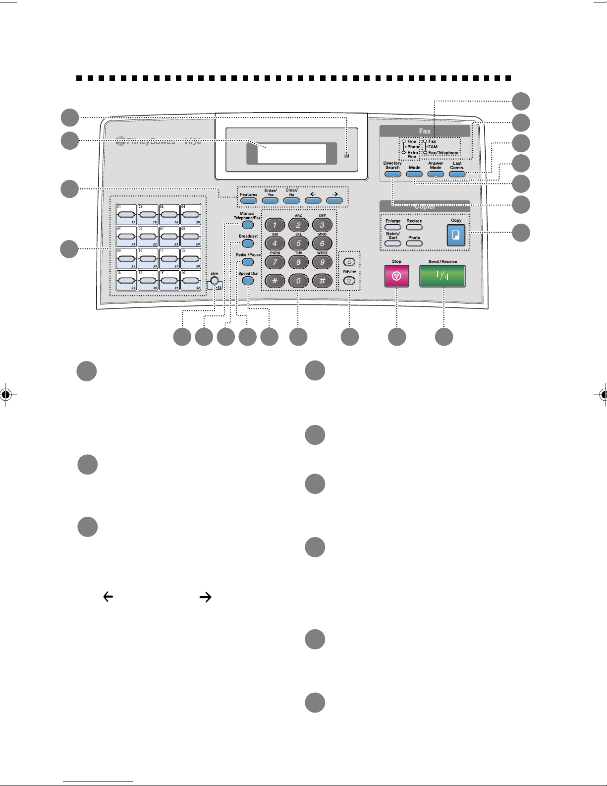
Control Panel Overview
1
20
19
2
18
17
3
16
15
14
4
5 6 7 8 9 10 11
1
Toner Empty Icon
The Toner icon flashes on and off
when toner is low, so you'll know
to order another toner cartridge.
You will be able to print until the
indicator stays on.
Liquid Crystal Display
2
(LCD)
Displays messages to help you set
up and operate your machine.
3
Programming Keys:
4
One T ouch Keys
These 16 keys give you instant
access to previously stored phone
numbers.
5
Shift
This key is used to access the “17”
through “32” One Touch numbers.
6
Manual T elephone/Fax
Lets you dial telephone and fax
numbers without lifting the
handset.
12
13
Feature
Lets you access the feature and
programming mode.
(Left Arrow) (Right
Arrow)
Moves the LCD cursor to the left
and right through options or text.
Enter/Yes
Stores a feature setting into the
machine.
Clear/No
Deletes entered data or backs up
one step in feature procedure.
1 - 2
INTRODUCTION
7
Broadcast
Also, you can use this key
whenever you want to send faxes
to many different locations
(maximum of 182 locations) at
once.
8
Redial/Pause
Re-dials the last number called.
Also inserts a pause in autodial
numbers.
9
Speed Dial
Lets you dial stored phone
numbers by pressing a two-digit
number.

10
20
Dial Pad
Dials phone and fax numbers and
can be used as a keyboard for
entering information into the
machine.
11
Volume Keys
Lets you adjust speaker, ring and
handset volume.
12
Stop
Stops a fax, cancels an operation
or exits from feature mode.
13
Send/Receive
Starts an operation (such as
sending a fax).
14
Copy Feature Keys:
Enlarge
Enlarges copies depending on the
ratio you select: 100%, 120%,
125%, 150%, 200% and
MANUAL.
Reduce
Reduces copies depending upon
the ratio you select: AUTO, 50%,
75%, 87%, 93%, 100% and
MANUAL. AUTO sets the
machine to calculate automatically
the reduction ratio that fits the size
of your paper. MANUAL allows
you to enter the reduction ratio
from 50%–100% using increments
of 1%.
15
Directory Search
Lets you look up numbers stored in
the dialing memory.
16
Mode
Sets the resolution when you send
a fax.
17
Answer Mode
Select how the machine will handle
incoming calls.
18
Last Comm.
You can use this key to print the
transmission verification Report
for your last transmission.
19
Resolution Indicator Lights
These LEDs show the resolution
mode you selected.
Answer Mode Indicator
Lights
These LEDs show how the
machine will handle incoming
calls.
Batch/Sort
Use this key when you want
multiple copies of a multiple page
original, copied in order.
Photo
This key is used to copy
photographs.
Copy
Makes a copy.
INTRODUCTION
1 - 3

About Your Machine
If you’re a first-time fax machine user, fax operation might seem a little
mysterious. Soon, you’ll recognize the unusual fax tones on your phone line,
and be able to send and receive faxes easily.
Fax Tones and Handshake
When someone is sending a fax, the machine sends fax calling tones, (CNG
tones)—soft, intermittent beeps at 4-second intervals. You’ll hear them when
you dial and press
dialing. During that time, the sending machine must begin the “handshake” with
the receiving machine. Each time you use automatic procedures to send a fax,
you are sending CNG tones over the phone line. You’ll soon learn to listen for
these soft beeps each time you answer a phone on your fax line, so you can
know if you are receiving a fax message.
The receiving fax responds with fax receiving tones-loud, chirping sounds. A
receiving fax chirps for about 40 seconds over the phone line, and the screen
displays RECEIVING. If your machine is set to the Fax mode, it will answer
every call automatically with fax receiving tones. Even if the other party hangs
up, your machine continues to send the “chirps” for about 40 seconds, and the
screen continues to display RECEIVING. To cancel the receiving mode,
Stop
press
.
Send/Receive
, and they continue for about 40 seconds after
When your machine answers in Fax/Telephone mode, the machine listens for
CNG tones and then responds with receiving tones.
The fax “handshake” is the time in which the sending machine’s CNG tones and
the receiving machine’s “chirps” overlap. This must be for at least 2 to 4
seconds, so the machines can understand how each is sending and receiving the
fax. The handshake cannot begin until the call is answered, and the CNG tones
only last for about 40 seconds after the number is dialed. Therefore, it’s
important for the receiving machine to answer the call in as few rings as
possible.
When you have an external telephone answering device (TAM) on your fax line,
your TAM will determine the number of rings before the call is answered. Pa y
special attention to the directions in the Assembly and Connections chapter for
connecting a TAM to your machine.
ECM (Error Correction Mode)
The Error Correction Mode (ECM) is a way for the machine to check the
integrity of a fax transmission while it is in progress. ECM transmissions are
possible only between machines that both have the ECM feature. If they do,
you may send and receive fax messages that are continuously checked for their
integrity. Sufficient memory must be available in your machine for this feature
to work.
1 - 4
INTRODUCTION
2
Assembly and Connections
2
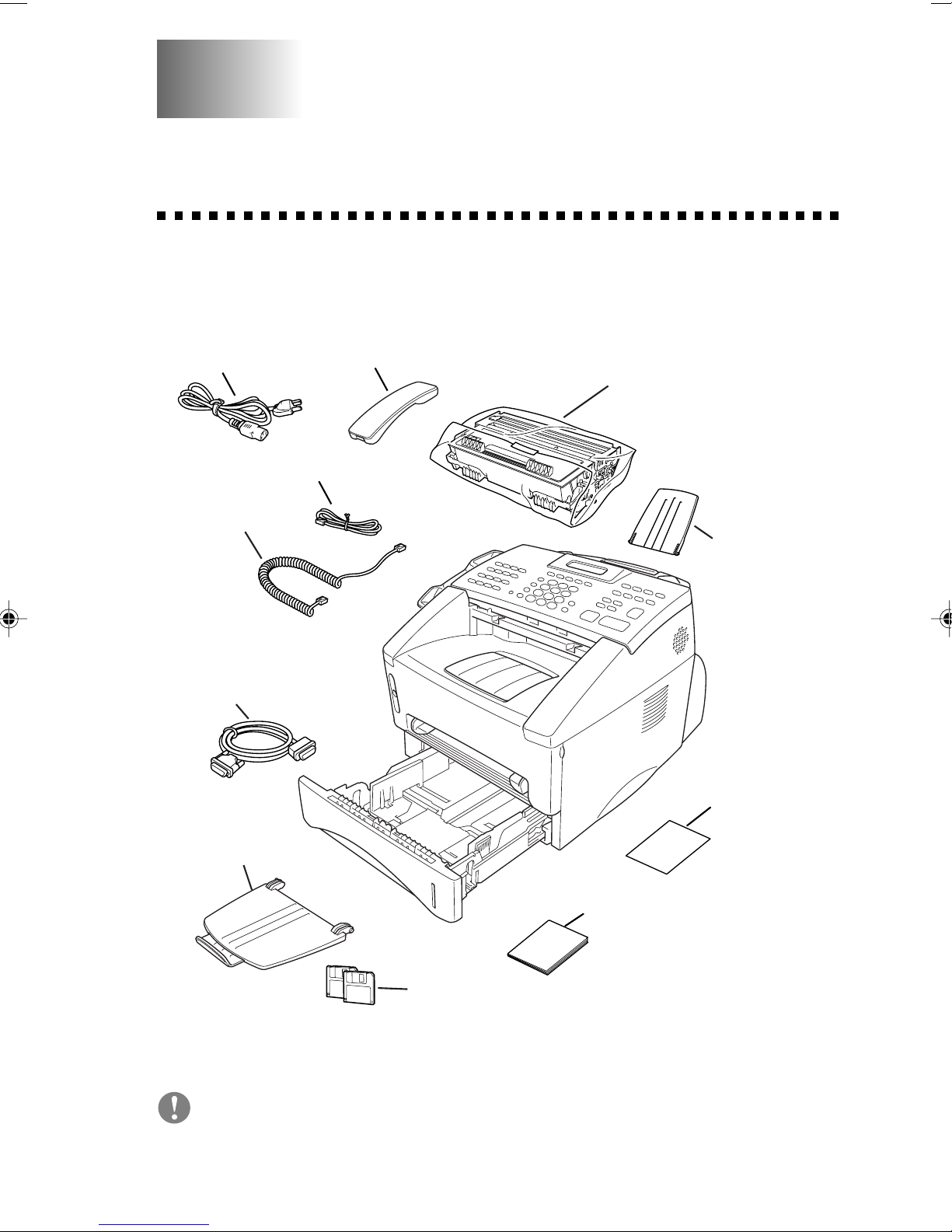
Packing List
Make sure you have the following items:
Power Cord
Telephone Wire Cord
Handset
Curled
Cord
IEEE-1284 Compliant
Bi-directioned Cable
Telephone Handset
Drum Unit Assembly
Document
Support
Quick Reference
Card
Document T ray
with Extension
Whenever you transport the machine, use the packing materials that came
with your machine.
Operating Guide
Floppy Disks
ASSEMBLY AND CONNECTIONS
2 - 1
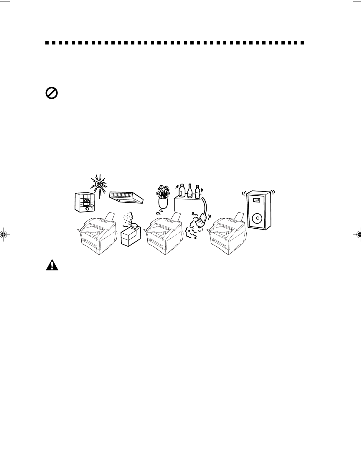
Choosing a Location
Place your machine on a flat, stable surface, such as a desk. Select a place
that is free of vibration and shocks. Locate the machine near a telephone
jack and a standard, grounded power outlet.
Avoid placing your machine in a high-traffic area. Do not place near
heaters, air conditioners, water, chemicals or refrigerators. Do not expose
the machine to direct sunlight, excessive heat, moisture or dust. Make
sure nothing blocks the flow of air from the fan on the sides of the
machine. Do not connect your machine to electrical outlets controlled by
wall switches or automatic timers. Disruption of power can wipe out
information in the unit’s memory. Do not connect your machine to
electrical outlets on the same circuit as large appliances or other
equipment that might disrupt the power supply. Avoid interference
sources, such as speakers or the base units of cordless phones.
NO !
WARNING
■
Never install telephone wiring during a lightning storm.
■
We recommend that this product be used with a surge protection device to
protect the product against lightning storms.
■
Never install a telephone jack in a wet location unless the jack is
specifically designed for a wet location.
■
Never touch telephone wires or terminals that are not insulated unless the
telephone line has been disconnected at the network interface.
■
Use caution when installing or modifying telephone lines.
■
Avoid using a telephone (other than a cordless type) during an electrical
storm. There may be a remote risk of electric shock from lightning.
NO !
NO !
■
Do not use the telephone to report a gas leak in the vicinity of the leak.
■
For PLUGGABLE EQUIPMENT, the socket-outlet should be installed
near the equipment and should be easily accessible.
■
To reduce the risk of shock or fire, use only a No. 26 AWG or larger
telecommunications line cord.
2 - 2
ASSEMBLY AND CONNECTIONS
Assembly
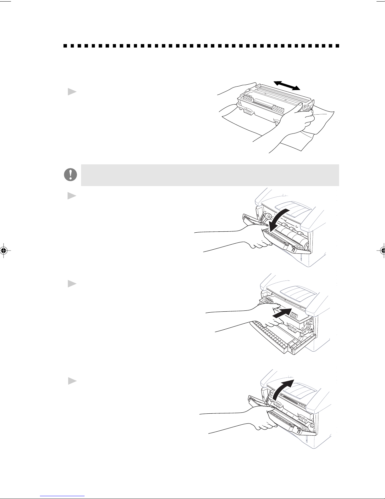
Installing the Drum Unit Assembly
(with T oner Cartridge)
Unpack the drum unit assembly,
1
including the toner cartridge, and
gently rock it from side to side
five or six times to distribute the
toner evenly inside the cartridge.
To prevent damage to the drum, do not expose it to light for
longer than a few minutes.
Open the front cover of the
2
machine.
Insert the drum unit assembly
3
into the machine.
Close the front cover.
4
ASSEMBLY AND CONNECTIONS
2 - 3
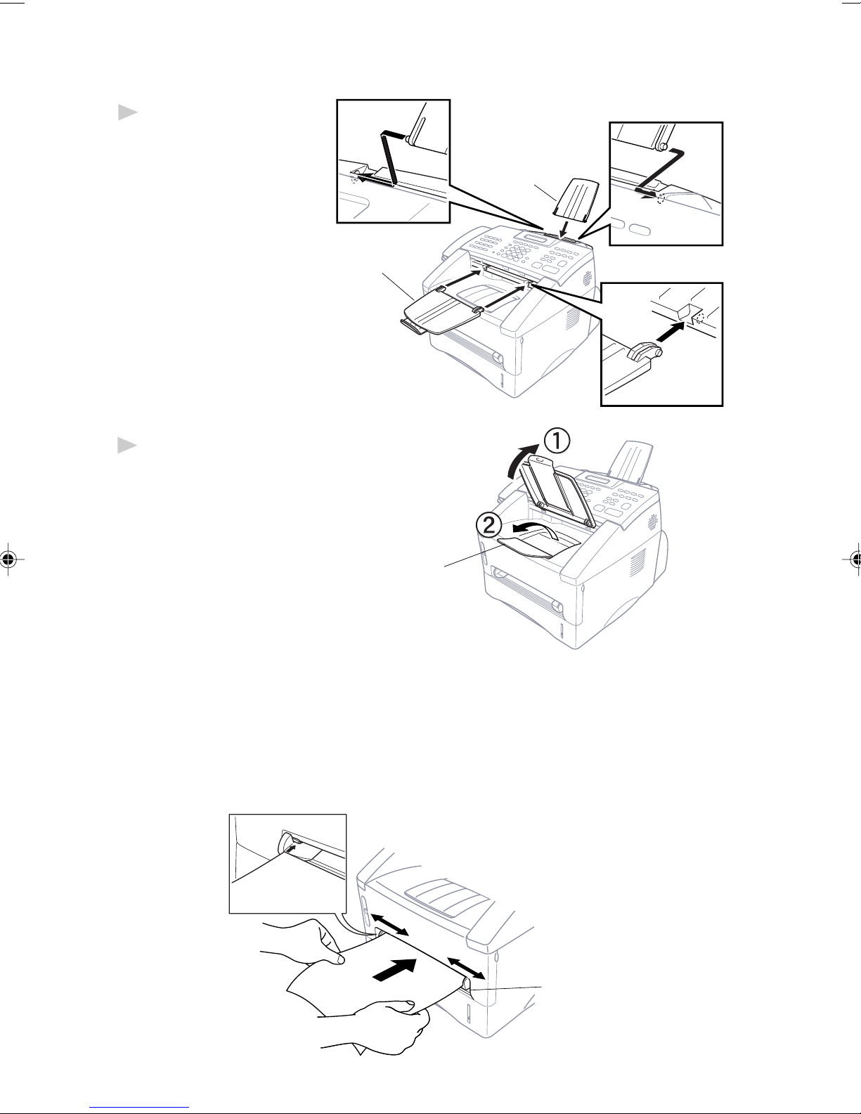
Attach the Trays
Attach the document
1
support and document
tray with extension,
and unfold the
extension, which holds
documents in place.
Document T ray
with Extension
Unfold the Front Output Bin
2
Extension, which holds printed
pages in place.
Document
Support
Front
Output Bin
Extension
Manual Feed Slot
The manual feed slot is above the multi-purpose paper cassette. Load paper
or envelopes one at a time. You do not have to remove paper from the paper
cassette.
To print or copy on labels, transparencies, card stock or thicker paper:
2 - 4
ASSEMBLY AND CONNECTIONS
Manual
Feed
Slot

Paper
Acceptable Paper
Multi-purpose cut sheet Letter, Legal, A4, A5, ISO B5, Executive, A6,
Paper Cassette #1: 2.75–8.5 x 4.57–14 inches (70–216 x 116–356 mm)
Manual Feed Slot: cut sheet Letter, Legal, A4, A5, B5 (JIS/ISO), Executive, A6
Paper Type Paper Size
2.75–8.5 x 4.57–14 inches (70–216 x 116–356 mm)
envelopes COM-10, Monarch, C5, DL
post cards 2.75–8.5 x 4.57–14 inches (70–216 x 116–356 mm)
®
organizer Day-Timer
J, K, L
2.75–8.5 x 4.57–14 inches (70–216 x 116–356 mm)
labels and 2.75–8.5 x 4.57–14 inches (70–216 x 116–356 mm)
transparencies
Paper Capacity of Paper Cassette
Multi-purpose Max. paper height is 1.06 inches (27 mm)
Paper Cassette #1: (use the guides) or approx. 250 sheets of
2
20 lb. (75 g/m
10 transparencies.
Front Output Bin: Approx. 150 sheets of 20 lb. (75 g/m
Letter/A4 paper
) Letter/A4 paper,
2
)
ASSEMBLY AND CONNECTIONS
2 - 5
Paper Specification for the Cassette
Cut Sheet
Basis Weight: 17 to 28 lb.
2
(64 to 105 g/m
Caliper: 0.003 to 0.005 inches.
(0.08 to 0.13 mm)
Moisture Content: 4% to 6% by weight
Manual Feed Slot
Cut Sheet Envelopes
Basis Weight: 17 to 42 lb. 20 to 24 lb.
(64 to 158 g/m
Caliper: 0.003 to 0.008 inches. 0.003 to 0.005 inches.
(0.08 to 0.2 mm) (0.084 to 0.14 mm)
)
2
) (75 to 90 g/m2)
Moisture Content: 4% to 6% by weight 4% to 6% by weight
Fax messages can be received on only Letter, Legal and A4 size paper.
If you use legal or A4, change the Paper Size setting:
Features
(
, 1, 2, 6.)
2 - 6
ASSEMBLY AND CONNECTIONS
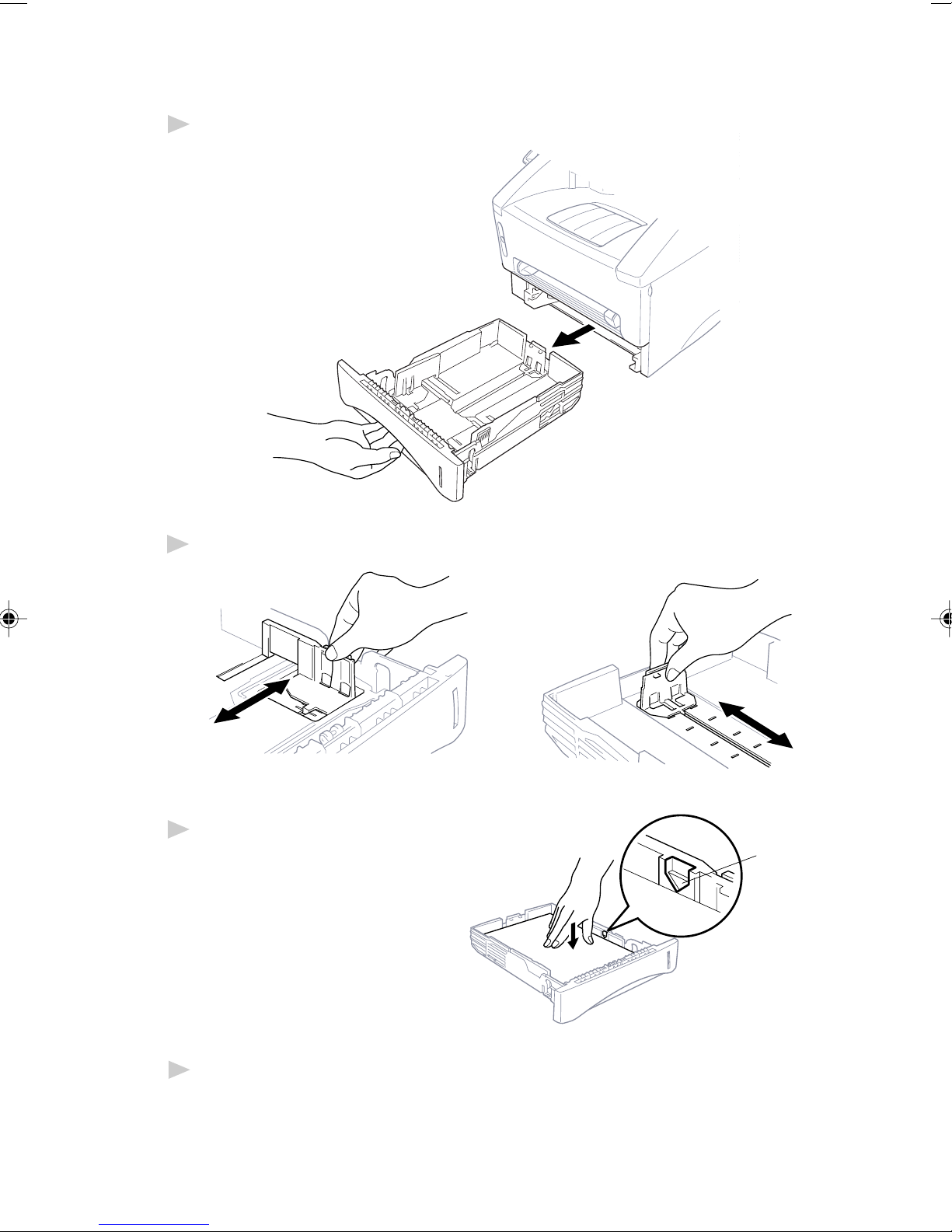
Loading Paper in Multi-purpose Paper Cassette
Pull the paper cassette completely out of the machine.
1
Slide the paper width and length adjusters for the paper size you want.
2
Fan the paper well. Load paper
3
in the paper cassette. Press
down on the paper to flatten
it in all four corners, keeping
the paper level below the
guide. The cassette can
hold up to 250 sheets of
20 lb (75g/m
2
) paper.
Maximum
Paper
Height
Guide
Slide the paper cassette into the machine until it locks into place.
4
ASSEMBLY AND CONNECTIONS
2 - 7
Connections
Connecting the Machine
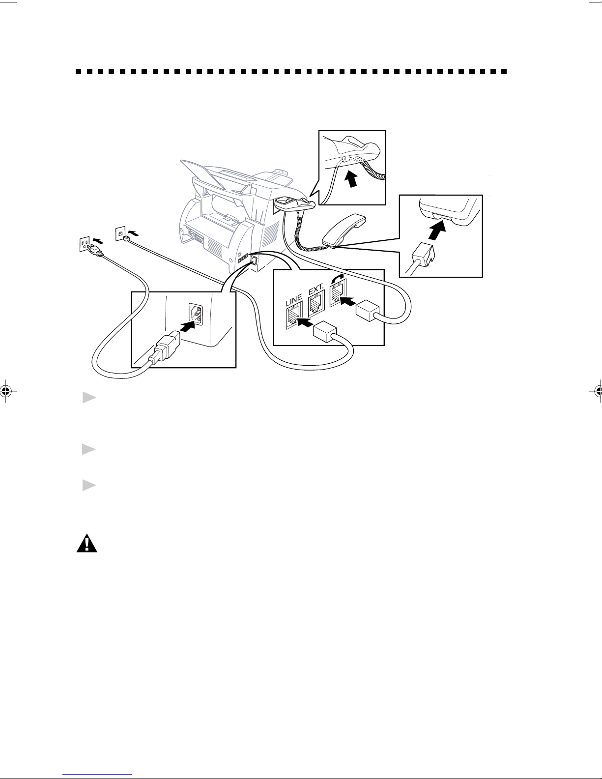
Connect the handset, power cord, and telephone line.
Connecting the Handset
1
Connect the curled handset cord to the bottom of the handset and the left
side of the machine.
Connect the Power Cord
2
When you connect the power, the screen will illuminate.
Connect the telephone line.
3
Connect one end of the telephone line cord to the jack labeled LINE on
the left side of the machine. Connect the other end to a modular wall jack.
WARNING
■
This machine must be grounded using a three-prong plug.
■
Since the machine is grounded through the power outlet, you can protect
yourself from potentially hazardous electrical conditions on the telephone line
by keeping the power to your machine on when you connect it to a telephone
line. When you want to move your machine, protect yourself by disconnecting
the telephone line first, and then the power cord.
■
Lightning and power surges can damage this product! We recommend that
you use a quality surge protection device on the AC power line as well as
on the telephone line, or unplug the lines during a lightning storm.
■
Do not touch the rollers at the paper exit.
2 - 8
ASSEMBLY AND CONNECTIONS

Connecting an External Telephone
Your machine is equipped with a handset that you can use as a regular
phone. However, you can also connect a separate telephone (or telephone
answering device) directly to your machine.
Connect the modular plug on the telephone’s line cord to the jack labeled
EXT. on the left side of the machine.
Whenever this phone (or TAM) is in use, the screen displays EXT. TEL IN
USE, and, if the machine handset is lifted, an alarm sounds. To disconnect
the call on the external phone and switch to the machine, press
Manual Telephone/Fax
.
Connecting an External TAM
(Telephone Answering Machine)
Sequence
You might choose to connect an answering system. When you have an
external TAM on the same telephone line as the machine, the TAM
answers all calls. The machine “listens” for fax calling (CNG) tones. If it
hears them, the machine takes over the call and receives the fax. If it
doesn’t hear CNG tones, the machine lets the TAM continue playing your
outgoing message so your caller can leave you a voice message.
The TAM must answer within four rings (the recommended setting is two
rings). The machine cannot hear CNG tones until the TAM has answered
the call, and with four rings there are only 8–10 seconds of CNG tones
left for the fax “handshake.” Make sure you carefully follow the
instructions in this manual for recording your outgoing message. We do
not recommend using the toll saver feature on your external answering
machine if it exceeds 4 rings.
Connections
The external TAM must be plugged into the left side of the machine in the
jack labeled EXT. Your machine cannot work properly if you plug the
TAM into a wall jack.
If You Subscribe to your Telephone Company’s Unique Ring Service:
You may connect an external TAM to a separate wall jack only if you
subscribe to your telephone company’s Unique Ring service, have
registered the unique ring pattern on your machine, use that number as a
fax number and set your machine’s Answer mode to MANUAL.
If You Do NOT Subscribe to Unique Ring Service:
You must plug your TAM into the EXT. jack of your machine. If your
TAM is plugged into a wall jack, both your machine and the TAM will try
to control the phone line. (See illustration on page 2-10.)
ASSEMBLY AND CONNECTIONS
2 - 9
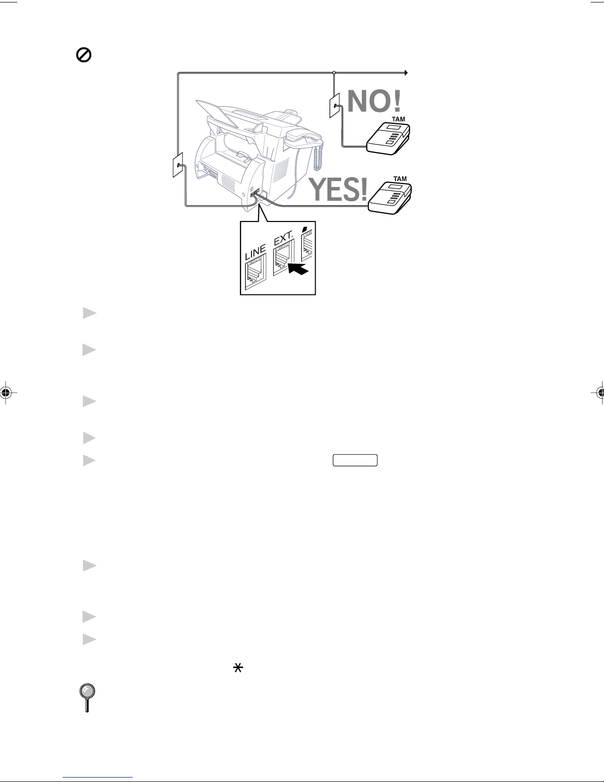
Do not connect a TAM elsewhere on the same phone line.
Plug the telephone line cord from the wall jack into the left side of the
1
machine, in the jack labeled LINE.
Plug the telephone line cord from your TAM into the left side of the
2
machine, in the jack labeled EXT. (Make sure this cord is connected to the
TAM at the TAM’s telephone line jack, and not its telephone set jack.)
Set your external TAM to four rings or less. (The machine’s Ring Count
3
setting does not apply).
Record the outgoing message. (See below.)
4
Set the Answer Mode to TAM by pressing
5
Fax/Telephone lights are on.
Answer Mode
until both Fax and
Recording Outgoing Message (OGM)
Timing is important in recording this message. The message sets up the
ways to handle both manual and automatic fax reception.
Record 5 seconds of silence at the beginning of your message. (This
1
allows your machine time to listen for the fax CNG tones of automatic
transmissions before they stop.)
Limit your speaking to 20 seconds. (See EXT.TEL.RX, page 5-3.)
2
End your 20-second message by giving your Fax Receive Code for people
3
sending manual faxes. For example: “After the beep, leave a message or
send a fax by pressing
We recommend beginning your OGM with an initial 5-second silence
because the machine cannot hear fax tones over a resonant or loud voice.
You may try omitting this pause, but if your machine has trouble
receiving, then you must rerecord the OGM to include it.
2 - 10
ASSEMBLY AND CONNECTIONS
5 1 and Start.”

Special Line Considerations
Roll Over Phone Lines
A roll over phone system is a group of two or more separate telephone
lines that pass incoming calls to each other if they are busy. The calls are
usually passed down or “rolled over” to the next available phone line in a
preset order.
Your machine can work in a roll over system as long as it is the last
number in the sequence, so the call cannot roll away. Do not put the
machine on any of the other numbers; when the other lines are busy and a
second fax call is received, the fax call would be transferred to a line that
does not have a fax machine. Your machine will work best on a dedicated
line.
Two-Line Phone System
A two-line phone system is nothing more than two separate phone
numbers on the same wall outlet. The two phone numbers can be on
separate jacks (RJ11) or combined into one jack (RJ14). Your machine
must be plugged into an RJ11 jack. RJ11 and RJ14 jacks may be equal in
size and appearance and both may contain four wires (black, red, green,
yellow). To test the type of jack, plug in a two-line phone and see if it can
access both lines. If it can, you must separate the line for your machine.
Converting T elephone Wall Outlets
There are three ways to convert to an RJ11 receptacle. The first two ways
may require assistance from the telephone company. You can change the
wall outlets from one RJ14 jack to two RJ11 jacks. Or, you can have an
RJ11 wall outlet installed and slave or jump one of the phone numbers to
it.
The third way is the easiest: Buy a triplex adapter. You can plug a triplex
adapter into an RJ14 outlet. It separates the wires into two separate RJ11
jacks (Line 1, Line 2) and a third RJ14 jack (Lines 1 and 2). If your
machine is on Line 1, plug the machine into L1 of the triplex adapter. If
your machine is on Line 2, plug it into L2 of the triplex adapter.
Triplex Adapter
RJ14
RJ11
ASSEMBLY AND CONNECTIONS
RJ14
2 - 11
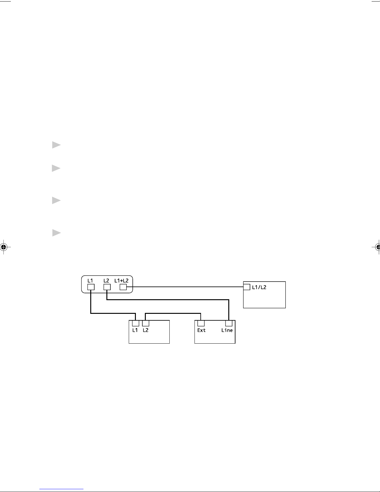
Installing Machine, External Tw o-Line TAM,
and T w o-Line Telephone
When you are installing an external two-line telephone answering
machine (TAM) and a two-line telephone, your machine must be isolated
on one line at both the wall jack and at the TAM. The most common
connection is to put the machine on Line 2, which is our assumption in the
following steps. The back of the two-line TAM must have two telephone
jacks: one labeled L1 or L1/L2, and the other labeled L2. You will need at
least three telephone line cords, the one that came with your machine and
two for your external two-line TAM. You will need a fourth line cord if you
add a two-line telephone.
Place the two-line TAM and the two-line telephone next to your
1
machine.
Plug one end of the telephone line cord for your fax machine into the L2
2
jack of the triplex adapter. Plug the other end into the LINE jack on the
left side of the machine.
Plug one end of the first telephone line cord for your TAM into the L1 jack
3
of the triplex adapter. Plug the other end into the L1 or L1/L2 jack of the
two-line TAM.
Plug one end of the second telephone line cord for your TAM into the L2
4
jack of the two-line TAM. Plug the other end into the EXT. jack on the left
side of the machine.
Triplex Adapter
Two Line Phone
Two Line
External TAM
FAX
You can keep two-line telephones on other wall outlets as always. There
are two ways to add a two-line telephone to the machine’s wall outlet. Yo u
can plug the telephone line cord from the two-line telephone into the
L1+L2 jack of the triplex adapter. Or, you can plug the two-line telephone
into the TEL jack of the two-line TAM.
2 - 12
ASSEMBLY AND CONNECTIONS

Multi-Line Connections (PBX)
Most offices use a central telephone system. While it is often relatively
simple to connect the machine to a key system or a PBX (Private Branch
Exchange), we suggest that you contact the company that installed your
telephone system and ask them to connect the machine for you. It is
advisable to have a separate line for the machine. You can then leave the
machine in FAX mode to receive faxes any time of day or night.
If the machine is to be connected to a multi-line system, ask your installer
to connect the unit to the last line on the system. This prevents the unit
from being activated each time a telephone call is received.
As with all fax units, this machine must be connected to a two wire
system. If your line has more than two wires, proper connection of the
machine cannot be made.
If you are installing the machine to work with a PBX:
It is not guaranteed that the unit will operate correctly under all
1
circumstances with a PBX. Any cases of difficulty should be reported first
to the company that handles your PBX.
If all incoming calls will be answered by a switchboard operator, it is
2
recommended that the Answer Mode be set to MANUAL. All incoming
calls should initially be regarded as telephone calls.
The machine may be used with either pulse or tone dialing telephone
3
service.
Custom Features on a Single Line
To learn how custom features may affect your faxing operations, please
see the Troubleshooting and Routine Maintenance chapter, page 17-1.
ASSEMBLY AND CONNECTIONS
2 - 13

2 - 14
ASSEMBLY AND CONNECTIONS
3
On-Screen Programming
3
User-Friendly Programming
We have designed your machine with on-screen programming. Userfriendly programming helps you take full advantage of all the features
your machine has to offer. (See Using This Manual, page 1-1.)
Since your fax programming is done on the LCD, we created step-by-step
on-screen prompts to help you program your machine. All you need to do
is follow the prompts as they guide you through the feature menu
selections and programming options and settings.
Feature Mode
You can access the feature mode by pressing
Feature mode, your machine displays a list of main menu options which
scroll on the display automatically; select one menu option by pressing
Enter/Yes
menu.
You can scroll more quickly by pressing
and see all options, in the opposite order.)
Before you press
pad, you can correct a mistake. Use
incorrect characters.
When you finish a feature, the screen displays ACCEPTED.
If you want to exit the Feature Mode, press
when it appears. The display then scrolls the options within that
Enter/Yes
after entering information in a field using the dial
to back up and then type over the
Features
. (Use to scroll backward
Stop
. When you enter the
.
ON-SCREEN PROGRAMMING
3 - 1
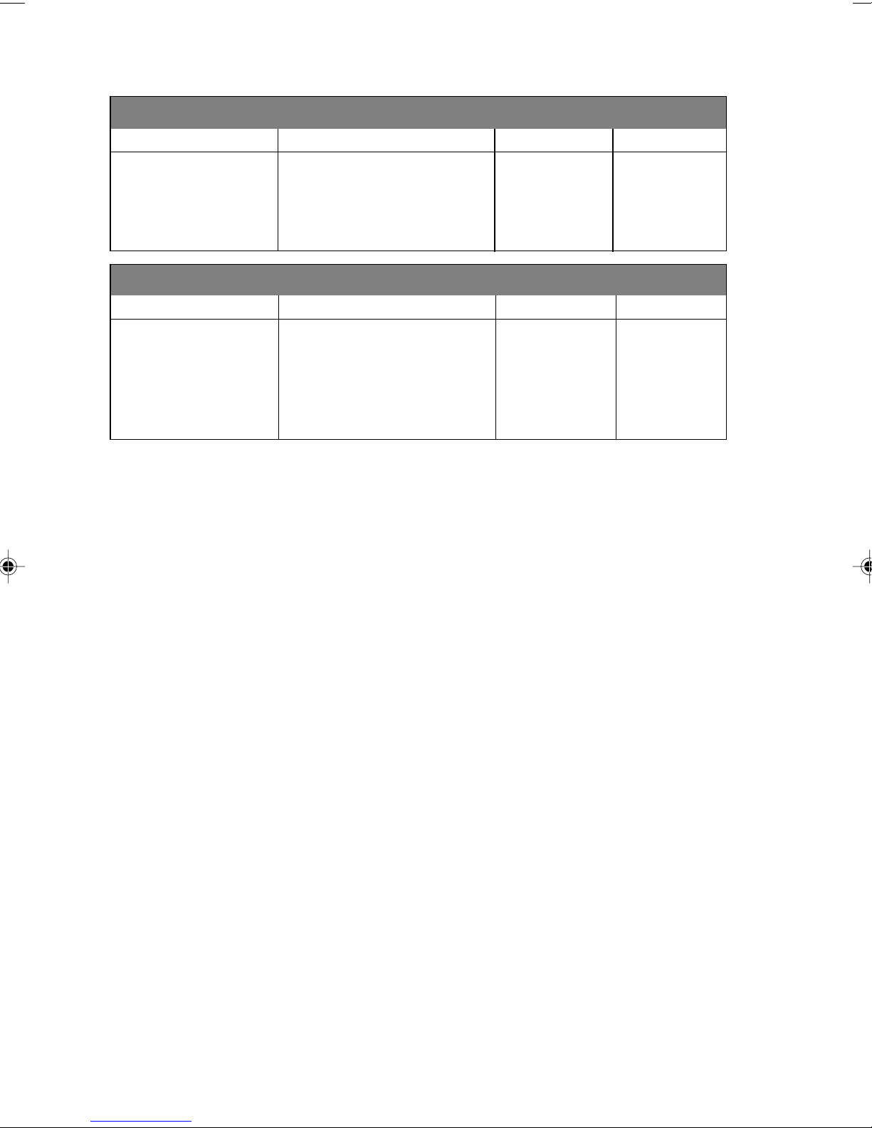
Feature Selection Table
If you have a basic understanding of how to program your machine, you
can perform most of the programming settings without this manual. To
help you understand the feature selections, options, and settings that are
found in your fax programs, use the Feature Selection Table below.
1. Fax Features
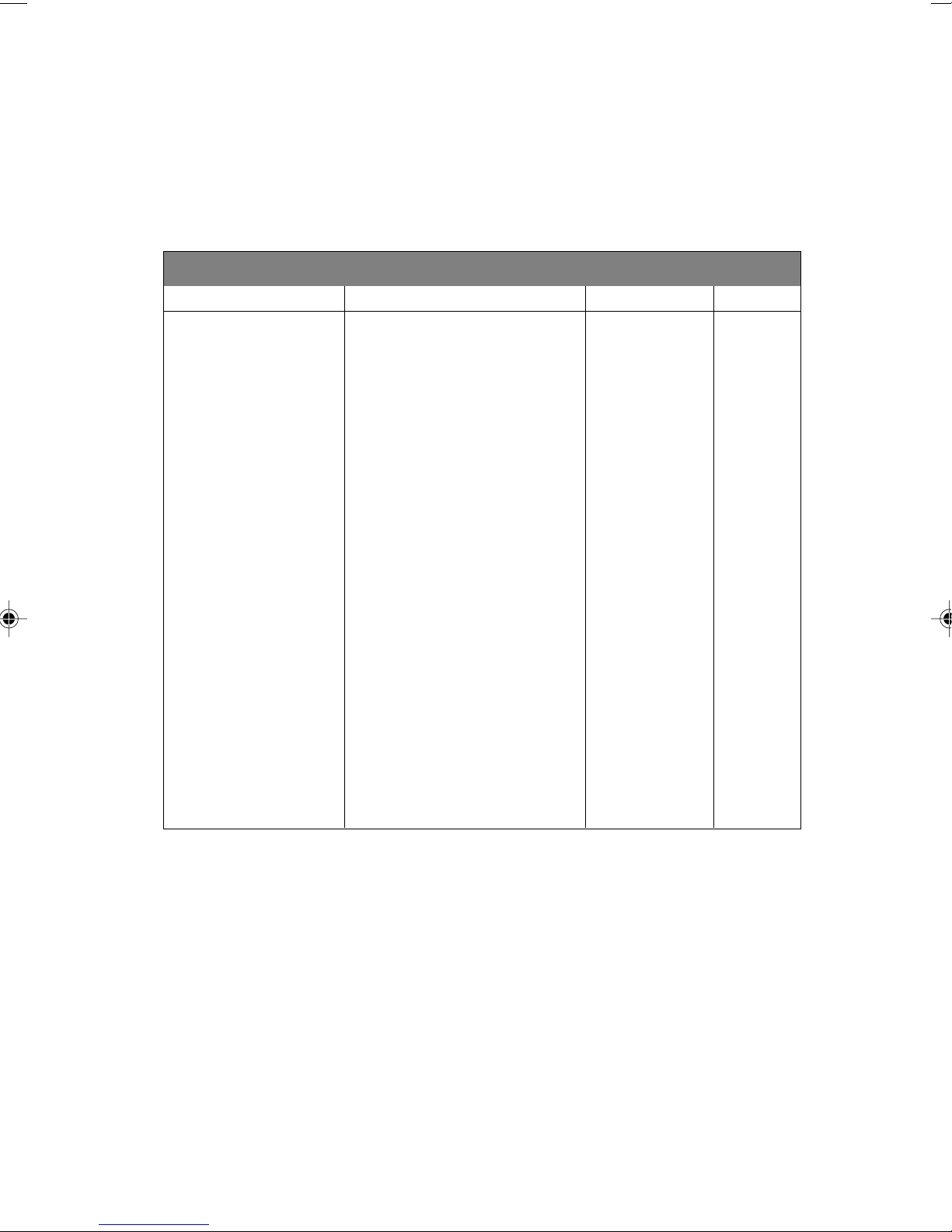
1. SYSTEM SETUP
Feature Description Factory Set Page
1. T ONE/PULSE Selects dialing mode. TONE 4-1
2. DATE/TIME Enter date and time for LCD — 4-1
display and heading on
transmissions.
3. MACHINE ID Program name, fax number and — 4-2
telephone number to appear on
each transmitted page.
4. BEEP VOL. Adjust volume level of beeper. LOW 4-4
5. SLEEP TIMER Conserve power 00 MIN 4-6
6. DELAYED SEND Sets the time of day for delayed 00:00 4-6
faxes. You can accept it or enter
another time.
7.
HANDSET VOLUME
For the hearing-impaired, you can OFF 4-5
set the volume to the
V OL AMPLIFY:ON setting on a
temporary or permanent basis.
8. CASSETTE #2 T urn CASSETTE #2 ON if you OFF 5-3
purchased the optional Cassette
#2.
0. LANGUAGE Changes the local language to ENGLISH
French.
3 - 2
ON-SCREEN PROGRAMMING
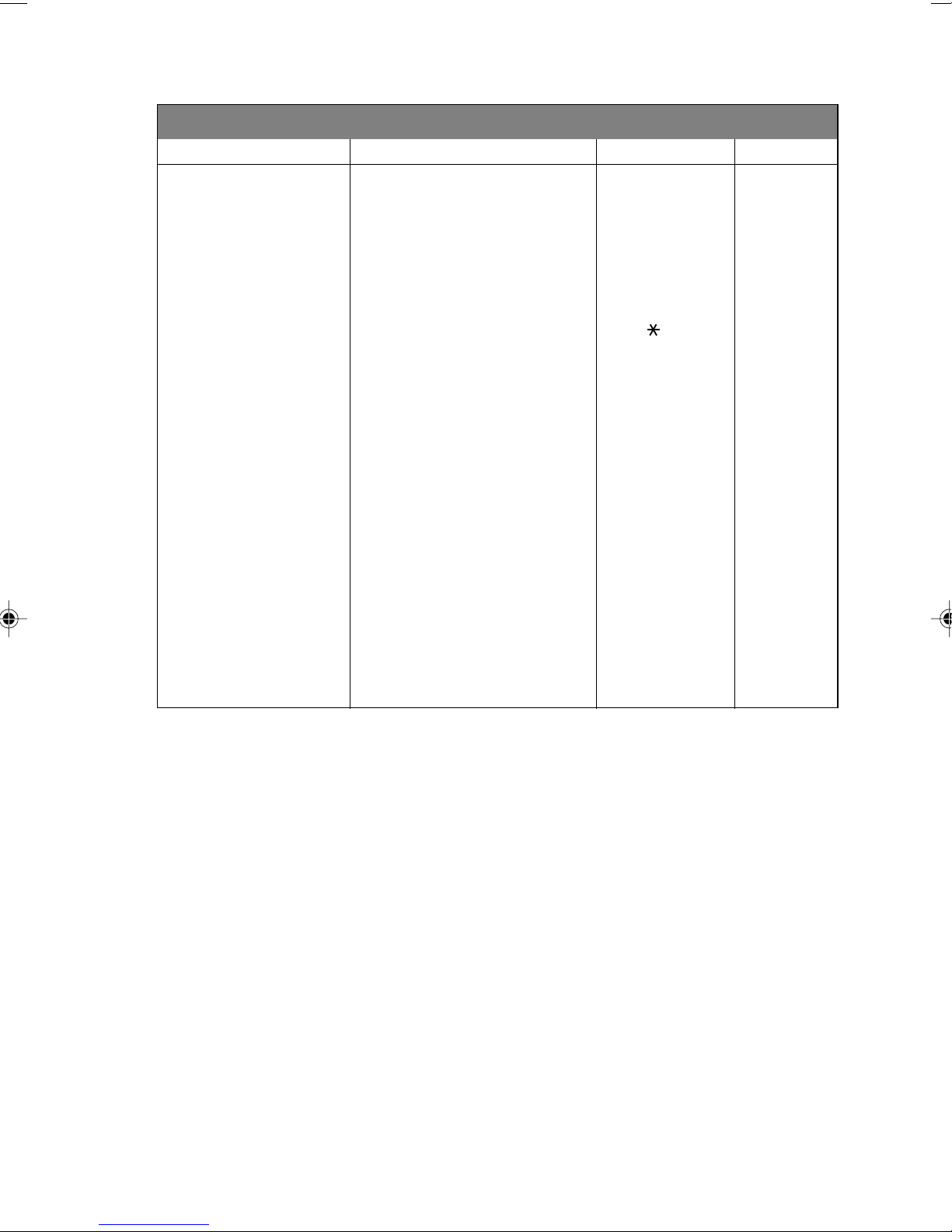
1. Fax Features (CONTINUED)
2. RX SETTINGS
Features Description Factory Set Page
1. RING COUNT Number of rings before machine 01 5-2
answers in F AX or FAX/TEL mode.
2. F/T RING TIME Sets the time for “double ring” in 20 SEC 5-2
FAX/TEL mode.
3. EXT.TEL.RX Receive fax messages without ON 5-3
pressing the Start key.
4. REMOTE CODE Enter code to activate or deactivate ON (
machine from a remote location.
5. RX REDUCE Reduces size of image. AUTO 5-4
If the optional cassette #2 is
attached, you can select the
reduction ratio for each cassette.
6. PAPER Selects size of paper for fax — 5-5
receiving.
If the optional cassette #2 is
attached, you can select the
size of paper for each cassette
and choose the cassette you wish
to use first.
7. PRINT DENSITY Make prints dark er or lighter. — 5-6
51, #51) 5-7
8. POLL RX Turns Polling Receive ON or OFF. OFF 5-9
9. SAVE TONER Increases life of toner cartridge. OFF 5-6
ON-SCREEN PROGRAMMING
3 - 3
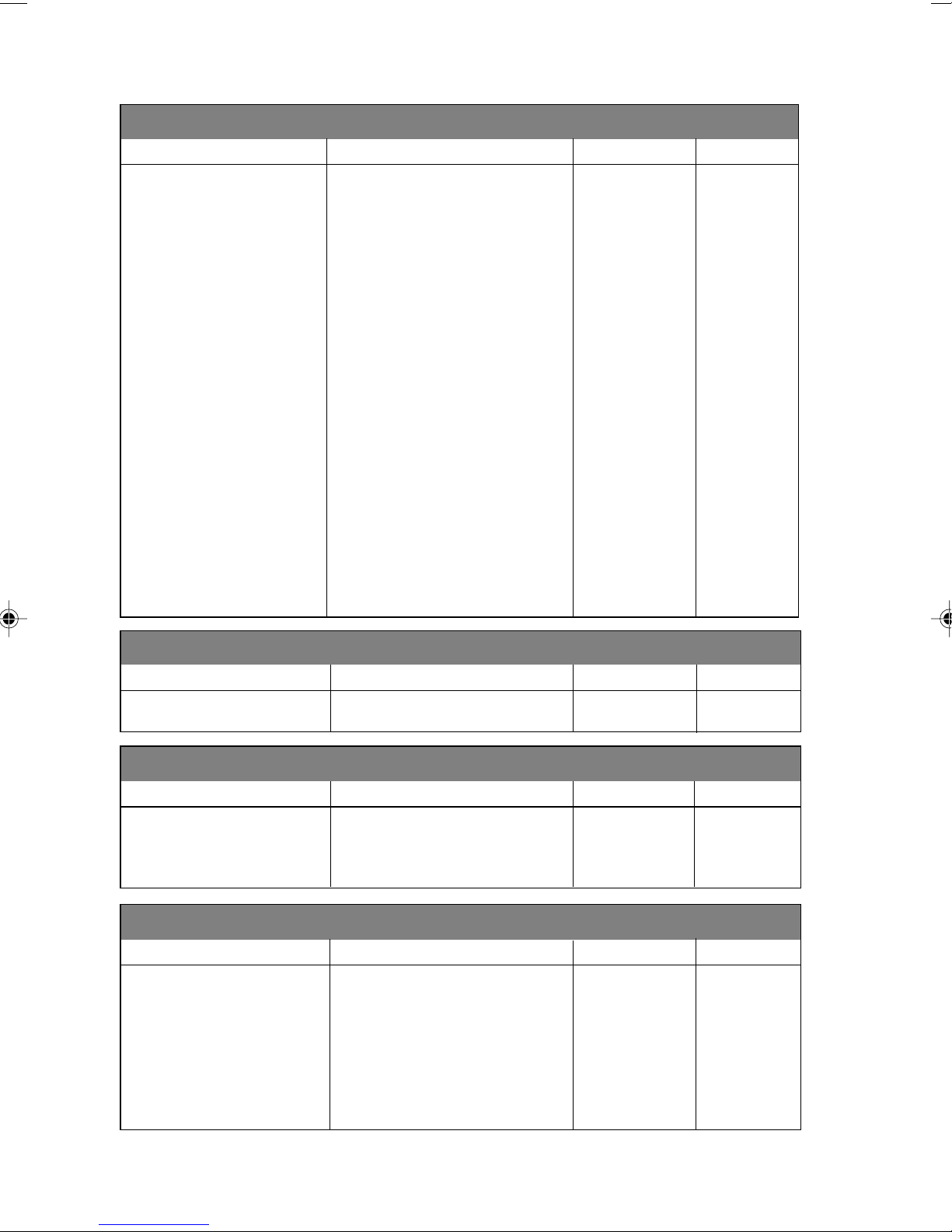
1. Fax Features (CONTINUED)
3. TX SETTINGS
Feature Description Factory Set Page
1. COVER SHEET Automatically sends the c over OFF 6-6, 7
page you programmed.
2. COVER MESSAGE Program customized message for — 6-6
fax cover page.
3. CONTRAST Change lightness or darkness of a AUTO 6-8
fax you are sending.
4. MODE Allows you to change resolutions STANDARD 6-12
page by page.
5. OVERSEAS MODE Adjusts for sometimes difficult OFF 6-9
overseas transmissions.
6. VOICE REQ. You can send a fax, then speak. OFF 6-9
7. DELAYED SEND Send documents later. — 6-10
8. POLL Turns Polling Transmission ON O FF 6-13
(or OFF).
9. TX FROM ADF Next Fax Only/ON/OFF OFF 6-3
0. BATCH TX Sends all delayed faxes that are OFF 6-11
to the same fax number and at the
same time as one transmission.
4. VIEW/DEL. JOBS
Feature Description Factory Set Page
Canceling a job in memory Cancel a delayed fax or polling job. — 5-10, 6-4
5. PRIORITY JOB
Feature Description Factory Set Page
Interrupting a polling Send a fax now, even if you have — 6-13
or transmit job the machine set to send a fax later ,
or if you have it set for Polling.
6. DIALER SETTING
Feature Description Factory Set Page
1. ONE TOUCH KEYS Dial numbers stored in memory — 7-1
by pressing only one key.
2. SPEED DIAL Dial numbers stored in memory — 7-2
by pressing only three keys.
3. SETUP GROUPS Set up a Group number for — 7-3
broadcasting.
3 - 4
ON-SCREEN PROGRAMMING
1. Fax Features (CONTINUED)
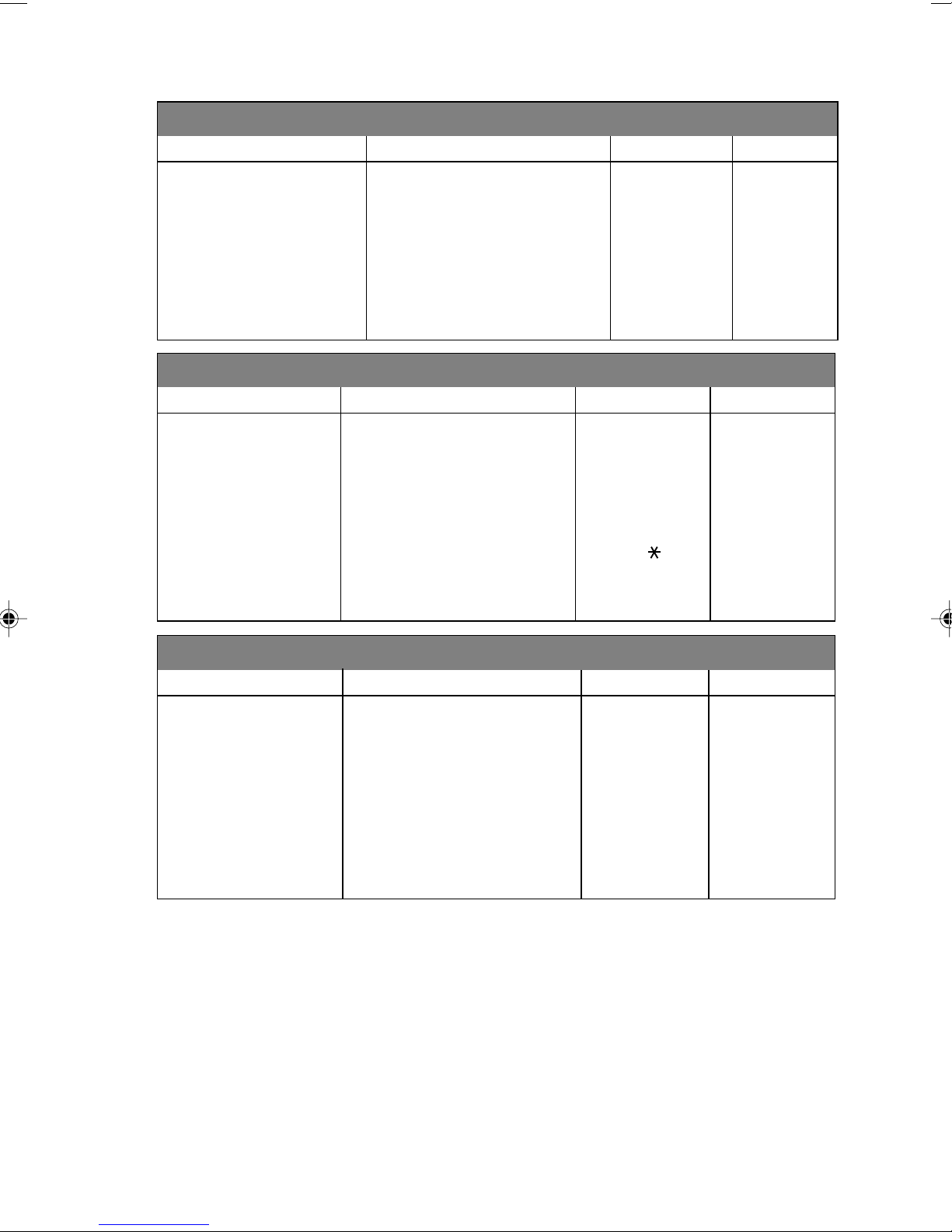
7. PRINT REPORTS
Feature Description Factory Set Page
1. JOB STATUS RPT INC 10-1
2. JOURNAL Print lists and reports INTERVAL:OFF 10-1
3. DIALER DIR. of activity. — 10-1
4. ALPHA DIR. (Details in Chapter 10) — 10-1
5. MACH. SETTINGS — 10-1
6. JOBS REPORT — 10-1
8. REMOTE FAX OPT
Feature Description Factory Set Page
1. FAX FWD/PAGE Set machine to forward fax OFF 9-1, 2
messages
—OR—call your pager .
2. REMOTE RTRV Store incoming faxes in memory O FF 9-2
for remote retrieval.
3. RR PASSCODE Set code for retrieving faxes. 159
4. PRINT FA X Print incoming faxes stored in — 5-8
the memory.
9-3
0. MISCELLANEOUS
Feature Description Factory Set Page
1. UNIQUE RING Use with telephone company’s OFF 5-12
distinctive ringing service to
register the ring pattern on the
machine.
2. CALLER ID View or print a list of the last 30 — 5-13, 14
Caller IDs stored in memory.
3. COPY CONTRAST You can make copies darker or — 11-1
lighter.
ON-SCREEN PROGRAMMING
3 - 5
2. Printer Features
1. PRINT OPTIONS
Feature Description Factory Set Page
1. INTERNAL FONT You can print resident fonts to — 14-8
check and confirm font types
2. CONFIGURATION Printer settings and status are — 14-8
listed here.
2. RESET PRINTER
Feature Description Factory Set Page
1. FACTORY SET You can restore the printer back — 14-8
to the factory default settings.
2. HEX DUMP MODE If you set HEX DUMP MODE, — 14-8
all the PC data is printed in
hexadecimal.
3 - 6
ON-SCREEN PROGRAMMING
Enter/Yes
Enter/Yes
4
System Setup
4
Getting Started
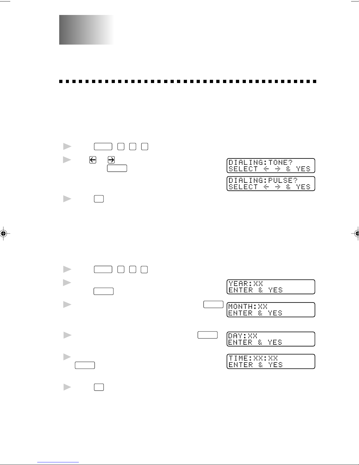
Setting Dialing Mode (Tone/Pulse)
Your machine comes set to accommodate tone (multi-frequency) dialing
service. If you have pulse (rotary) dialing service, you need to change the
dialing mode.
Press
1
Use or to select dialing mode
2
and press
Press
3
Features
Stop
, 1, 1, 1.
Enter/Yes
to exit.
.
Setting Date and Time
Your machine displays the date and time, and prints it on every fax you send.
In the event of a power failure, you may have to reset the date and time.
All other settings remain unaffected.
Press
1
Enter the last two digits of the year and
2
press
Enter two digits for the month and press
3
(For example, enter 09 for
September, or 10 for October).
Features
Enter/Yes
, 1, 1, 2.
.
.
Enter two digits for the day and press
4
(For example, 06).
Enter the time in 24-hour format and press
5
Enter/Yes
PM).
Press
6
The screen now displays the date and time you set, and displays it
whenever the machine is standing by.
. (For example, enter 15:25 for 3:25
Stop
.
.
SYSTEM SETUP
4 - 1
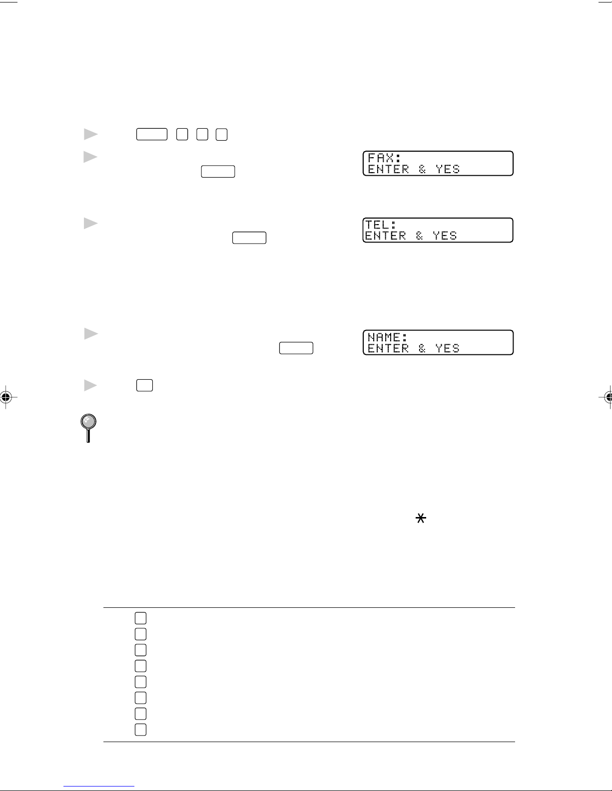
Setting Machine ID
You can store your name, fax number, and telephone number to be printed
on all fax pages you send. See Composing Electronic Cover Sheet, page
6-5.
Press
1
Enter your fax number (up to 20
2
digits) and press
Features
, 1, 1, 3.
Enter/Yes
.
You must enter a fax number
to proceed.
Enter your telephone number (up
3
to 20 digits) and press
Enter/Yes
.
If your telephone number and fax
number are the same, enter the
same number again.
The number appears on Cover
sheets and Call Back Messages.
Use the dial pad to enter your name
4
(up to 20 characters) and press
Enter/Yes
.
(See Entering Text.)
5
Press
Stop
.
The screen returns to the date and time.
If your Machine ID has already been programmed, the screen prompts “1”
to make a change, or “2” to exit without changing.
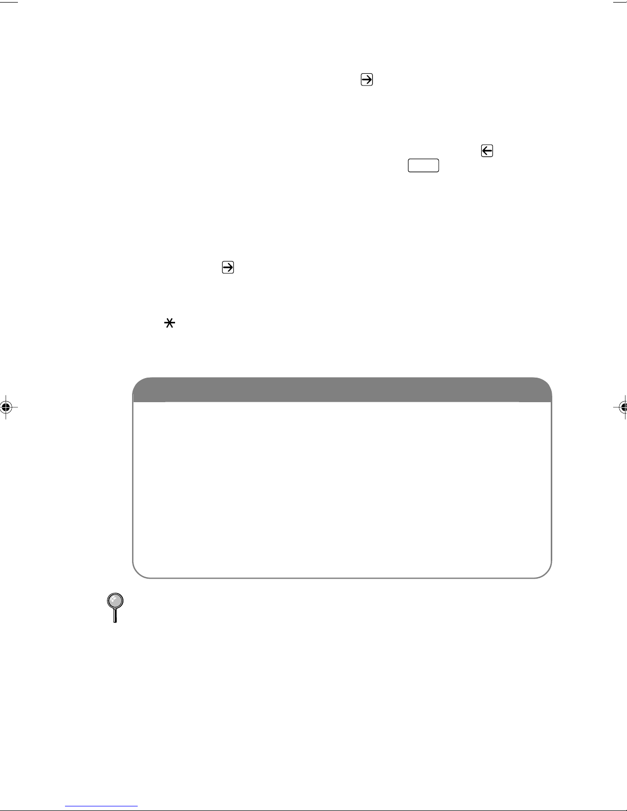
Entering T ext
When you are setting certain features, such as the Machine ID, you may
need to enter text into the machine. Most keys on the dial pad have three
or four letters printed above them. The keys for 0, # and
don’t have
printed letters because they are used for special characters.
By pressing the appropriate number on the dial pad the correct number of
times, you can access the character you want.
Key once twice three times four times five times
2
3
4
5
6
7
8
9
AB C2A
DE F3D
GH I 4G
JK L5J
MN O 6M
PQ RS7
TU V8T
WX Y Z 9
4 - 2
SYSTEM SETUP
Inserting spaces
If you want to enter a blank space, press once between numbers and
twice between characters.
Making corrections
If you entered a letter incorrectly and want to change it, press to move
the cursor after the last correct letter. Then press
Clear/No
; all letters above
and to the right of the cursor are deleted. Re-enter the correct text and/or
digits. Also, you can back up and type over incorrect letters.
Repeating letters
If you need to enter a character assigned to the same key as the previous
character, press
to move the cursor to the right.
Special characters and symbols
Press for (space) ! “ # $ % & ’ ( ) * + , - . /
Press # for : ; < = > ? @ [ ] ^ _
Press Ø for É À È Ê Î Ç Ë Ö 0
NOTICE
The Telephone Consumer Protection Act of 1991 makes it unlawful
for any person to use a computer or electronic device to send any
message via a telephone fax machine unless such messages clearly
contain, in a margin at the top or bottom of each transmitted page, or
on the first page of the transmission, the date and time it is sent and
an identification of the business or other entity or other individual
sending the message and the telephone number of the sending
machines or such business, other entity or individual.
In order to program this information into your fax machine, you
should complete the steps described on pages 4-1 and 4-2.
The telephone number you enter is used only for Call Back Message and
Cover Sheet features.
SYSTEM SETUP
4 - 3
Setting Beep Volume
You can set the beep volume to LOW, HIGH or OFF. The default setting is
LOW. When the beep volume is set to LOW or HIGH, the machine beeps
every time you press a key or make an error, and at the end of fax sending
or receiving.
Press
1
Press or to select your setting and press
2
Press
3
Features
Stop
, 1, 1, 4.
to exit.
Enter/Yes
.
Choosing the Handset Volume
Before you begin to use the machine, you must decide if you need to set
the handset volume to AMPLIFY:ON for a user who is hearing-impaired.
The AMPLIFY:ON volume level complies with FCC standards.
AMPLIFY VOL: OFF
This default setting is appropriate if none of the users are hearingimpaired. During a conversation, users can press Volume
control panel to adjust the volume to LOW or HIGH. When the handset is
replaced, the handset volume will remain until you change it again.
AMPLIFY VOL: ON—TEMPORARY
This setting is appropriate if some of the users are hearing-impaired.
During a conversation, users can press Volume
or on the control
panel to adjust the volume to LOW, HIGH or AMPLIFY. When the
handset is replaced, the handset volume returns to the default setting of
LOW.
or on the
AMPLIFY VOL:ON—PERMANENT
Choose AMPLIFY V OL:ON—PERMANENT if all of the users are
hearing-impaired. During a conversation, users can press Volume
on the control panel to adjust the volume to LOW, HIGH or AMPLIFY.
When the handset is replaced, the handset volume returns to the default
setting of AMPLIFY.
When you press Volume or on the control panel to adjust the
volume, the display shows the setting you are choosing. Each key press
changes the volume to the next setting.
WARNING
It is important that you do not choose PERMANENT unless all the
users are hearing-impaired. Otherwise, the default setting of AMPLIFY
may damage the hearing of some users.
4 - 4
SYSTEM SETUP
or
 Loading...