

Page 1
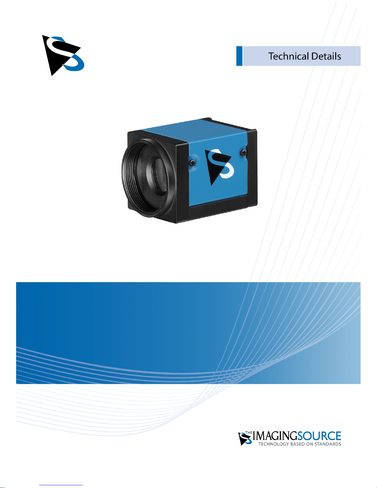
DMK 33UX183
Technical Reference Manual
Page 2

DMK 33UX183 Technical Reference Manual
2
Table of Contents
1. Quick Facts 4
2. Dimensional Diagrams 6
2.1 DMK 33UX183 C-Mount with Tripod Adapter ............................................................. 6
2.2 DMK 33UX183 C-Mount without Tripod Adapter ....................................................... 7
2.3 DMK 33UX183 CS-Mount with Tripod Adapter ........................................................... 8
2.4 DMK 33UX183 CS-Mount without Tripod Adapter ..................................................... 9
3. I/O Connector 10
3.1 12-pin I/O Connector ................................................................................................... 10
TRIGGER_IN ........................................................................................................... 113.1.1
STROBE_OUT ......................................................................................................... 113.1.2
4. Spectral Characteristics 12
4.1 Spectral Sensitivity - IMX183CLK-J ............................................................................. 12
5. Camera Controls 13
5.1 Sensor Readout Control .............................................................................................. 13
Pixel Format ........................................................................................................... 135.1.1
8-Bit Monochrome ................................................................................................................................. 135.1.1.1
12-Bit Packed Monochrome ................................................................................................................ 145.1.1.2
16-Bit Monochrome .............................................................................................................................. 145.1.1.3
Resolution .............................................................................................................. 145.1.2
Readout Modes ...................................................................................................... 155.1.3
Frame Rate ............................................................................................................. 165.1.4
Partial Scan Offset ................................................................................................. 175.1.5
Image Flipping ....................................................................................................... 185.1.6
5.2 Image Sensor Control .................................................................................................. 18
Exposure Time ....................................................................................................... 185.2.1
Gain ........................................................................................................................ 195.2.2
Black Level ............................................................................................................. 195.2.3
5.3 Automatic Exposure and Gain Control ...................................................................... 20
Auto Exposure ........................................................................................................ 205.3.1
Auto Gain ............................................................................................................... 205.3.2
Auto Reference Value ............................................................................................ 215.3.3
Highlight Reduction ............................................................................................... 215.3.4
Auto Exposure Limits ............................................................................................. 215.3.5
Auto Gain Limits .................................................................................................... 225.3.6
5.4 Trigger ........................................................................................................................... 23
Trigger Mode ......................................................................................................... 235.4.1
Trigger Polarity ...................................................................................................... 235.4.2
Trigger Operation .................................................................................................. 245.4.3
Software Trigger .................................................................................................... 245.4.4
Page 3

DMK 33UX183 Technical Reference Manual
3
Table of Contents
Trigger Burst Count ................................................................................................ 245.4.5
Trigger Source ........................................................................................................ 255.4.6
Trigger Overlap ...................................................................................................... 255.4.7
5.5 Trigger Timing Parameters .......................................................................................... 25
Trigger Delay ......................................................................................................... 265.5.1
Trigger Debounce Time ......................................................................................... 265.5.2
Trigger Mask Time ................................................................................................. 265.5.3
Trigger Noise Suppression Time ............................................................................ 275.5.4
5.6 Digital I/O ..................................................................................................................... 27
General Purpose Input ........................................................................................... 275.6.1
General Purpose Output ........................................................................................ 285.6.2
5.7 Strobe ........................................................................................................................... 28
Strobe Enable ......................................................................................................... 285.7.1
Strobe Polarity ........................................................................................................ 295.7.2
Strobe Operation .................................................................................................... 295.7.3
Strobe Duration ...................................................................................................... 305.7.4
Strobe Delay ........................................................................................................... 305.7.5
5.8 Image Processing ......................................................................................................... 30
Gamma ................................................................................................................... 305.8.1
Lookup Table .......................................................................................................... 315.8.2
5.9 Region of Interest for Auto Functions ....................................................................... 32
Auto Functions ROI Enable .................................................................................... 325.9.1
Auto Functions ROI Preset ..................................................................................... 325.9.2
Auto Functions ROI Custom Rectangle .................................................................. 335.9.3
5.10 User Sets ....................................................................................................................... 34
User Set Selector .................................................................................................... 345.10.1
Load User Set ......................................................................................................... 345.10.2
Save User Set ......................................................................................................... 355.10.3
Default User Set ..................................................................................................... 355.10.4
6. Revision History 36
Page 4
DMK 33UX183 Technical Reference Manual
4
Quick Facts
1 Quick Facts
General
Vision Standard
USB3 Vision
Dynamic Range
12
Resolution
5472x3648
Frame Rate at Full Resolution
18
Pixel Formats
8-Bit Monochrome
12-Bit Packed Monochrome
16-Bit Monochrome
Optical Interface
IR-Cut filter
No
Sensor Type
Sony IMX183CLK-J
Shutter Type
Rolling
Sensor Format
1 inch
Pixel Size
2.4 µm
Lens Mount
C/CS
Electrical Interface
Interface
USB 3.0
Supply voltage
4.75 VDC to 5.25 VDC
Current consumption
approx 660 mA @ 5 VDC
I/O Connector
12-pin connector for trigger and strobe or
general purpose input/output
Mechanical Data
Dimensions
H: 29 mm, W: 29 mm, L: 43 mm
Mass
65 g
Adjustments
Shutter
50 µs to 30 s
Gain
0 dB to 2704 dB
Page 5

DMK 33UX183 Technical Reference Manual
5
Quick Facts
Environmental
Temperature (operating)
-5 °C to 45 °C
Temperature (storage)
-20 °C to 60 °C
Humidity (operating)
20 % to 80 % (non-condensing)
Humidity (storage)
20 % to 95 % (non-condensing)
Page 6
DMK 33UX183 Technical Reference Manual
6
Dimensional Diagrams
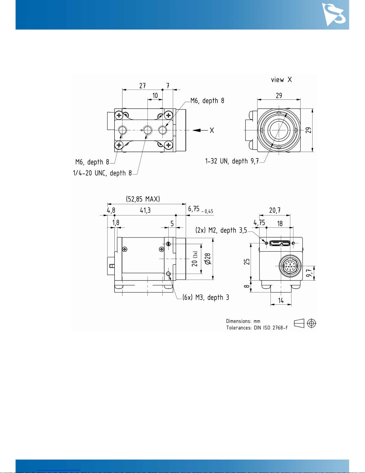
2 Dimensional Diagrams
2.1
DMK 33UX183 C-Mount with Tripod Adapter
Page 7
DMK 33UX183 Technical Reference Manual
7
Dimensional Diagrams
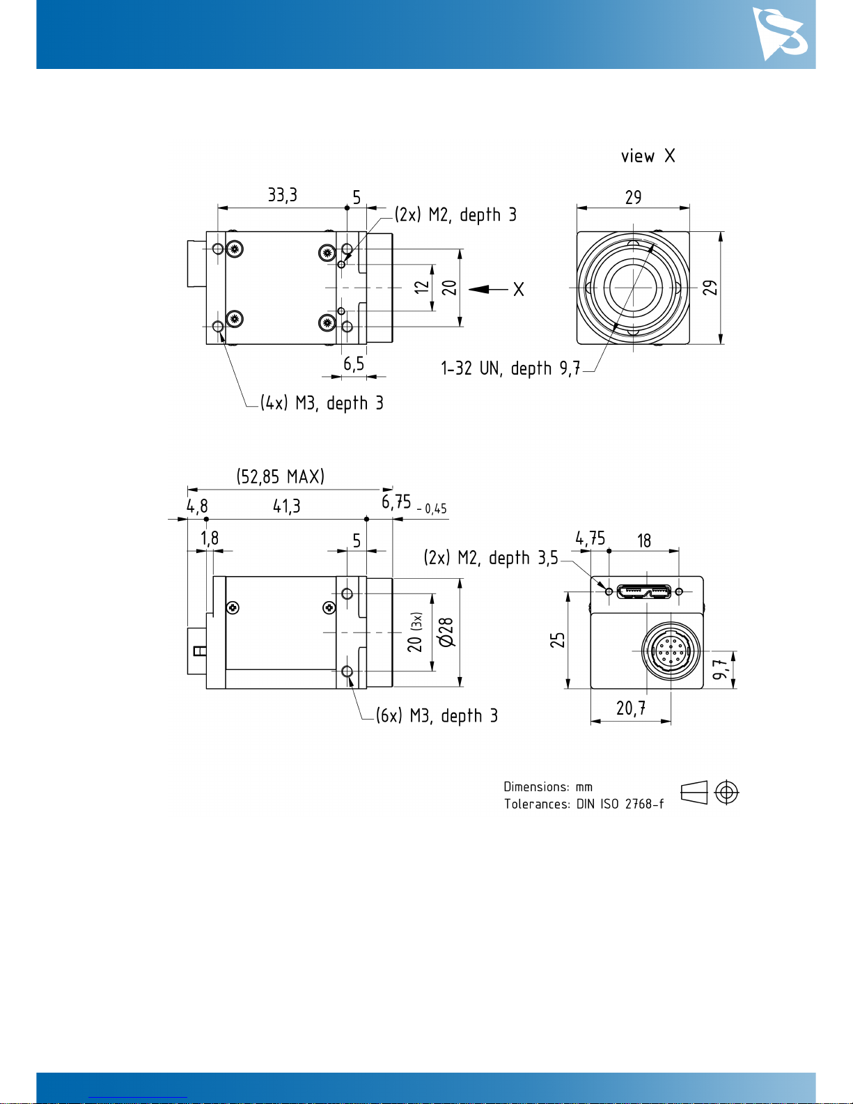
2.2
DMK 33UX183 C-Mount without Tripod Adapter
Page 8

DMK 33UX183 Technical Reference Manual
8
Dimensional Diagrams
2.3
DMK 33UX183 CS-Mount with Tripod Adapter
Page 9
DMK 33UX183 Technical Reference Manual
9
Dimensional Diagrams
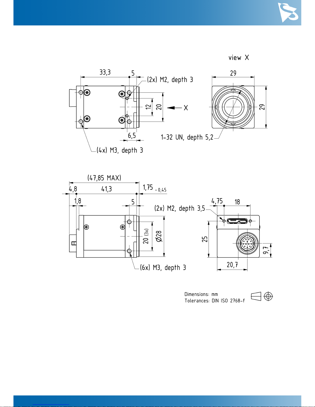
2.4
DMK 33UX183 CS-Mount without Tripod Adapter
Page 10
DMK 33UX183 Technical Reference Manual
10
I/O Connector
3 I/O Connector
3.1
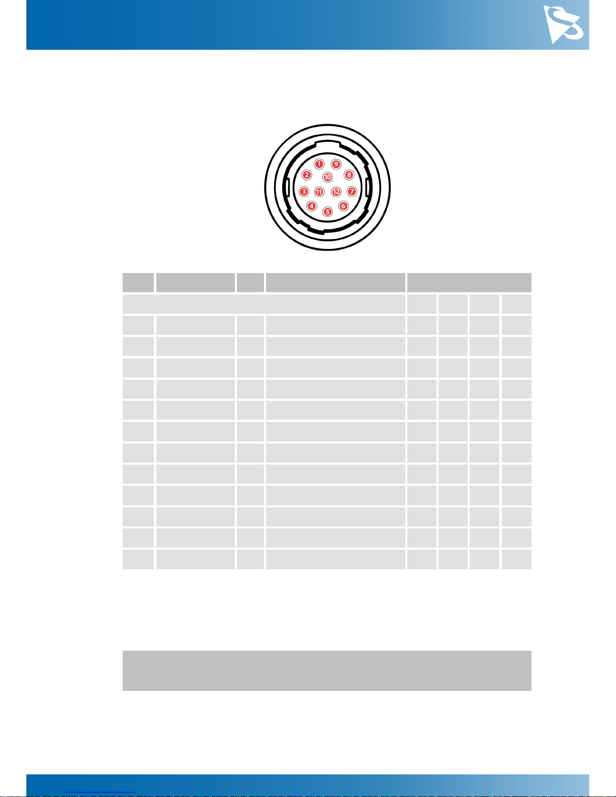
12-pin I/O Connector
Rear view of camera
Pin
Signal
I/O
Remarks
Characteristics
Min
Typ
Max
Unit
1
do not use
-----2do not use
-----3n.c.-----4
n.c.-----5
n.c.-----6
n.c.-----7
GND_I/O
G3External Ground
----8
n.c.-----9
n.c.-----10
STROBE_OUT
O3Open drain
--24.01V11TRIGGER_IN (+)
I3Optocoupler signal
3.32-
24.02V12TRIGGER_IN (-)
I3Optocoupler ground
---
-
1
max. 0.2A (ID) for open drain MOSFET!
2
min. 3.5 mA driver strength required!
3
G: Ground O: Output I: Input
The part number of this Hirose connector is HR10A10R-12P(73). To create an I/O
cable you need a Hirose connector HR10A-10P-12S(73).
Page 11

DMK 33UX183 Technical Reference Manual
11
I/O Connector
3.1.1
TRIGGER_IN
The TRIGGER_IN line can be used to synchronize the start of the exposure time with
external events. The Trigger section describes in detail how the image sensor's behavior
can be controlled.
The current input signal can also be read directly through the General Purpose Input
feature.
3.1.2
STROBE_OUT
The STROBE_OUT line's main usage is to indicate the integration time of the image
sensor which allows flashes, strobes or other light sources to be synchronized with
camera operation. The line's behavior can be controlled through the Strobe controls.
The output signal can also be directly controlled through the General Purpose Output
feature.
Page 12
DMK 33UX183 Technical Reference Manual
12
Spectral Characteristics
4 Spectral Characteristics
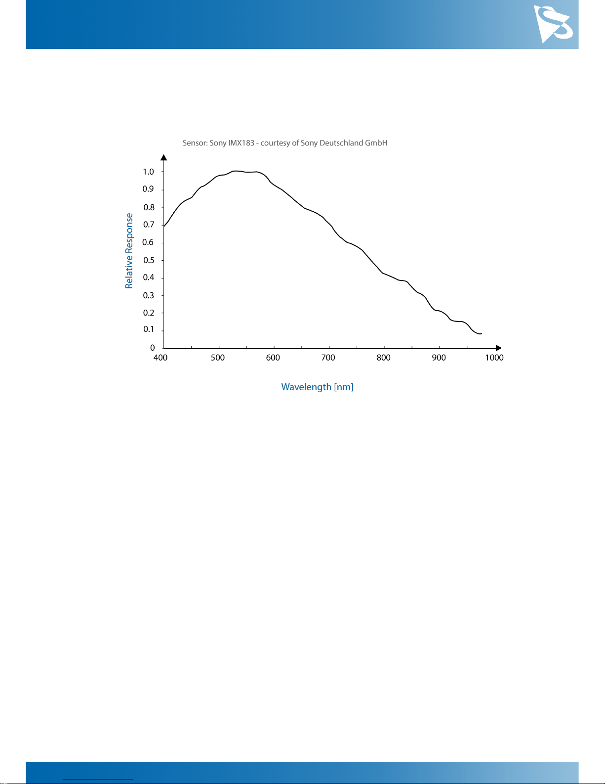
4.1
Spectral Sensitivity - IMX183CLK-J
Page 13
DMK 33UX183 Technical Reference Manual
13
Camera Controls
5 Camera Controls
This section describes the parameters available for the DMK 33UX183 camera.
The actual name of the parameter depends on the driver technology used to access the
camera. Parameter names are listed for the most common ways to access the cameras:
·
USB3 Vision (cross platform, via 3rd party driver)
·
UVC/V4L2 (on Linux, via uvcvideo)
·
IC Imaging Control (on Windows, via Device Driver for The Imaging Source USB 33U,
37U and 38U Cameras)
5.1
Sensor Readout Control
5.1.1
Pixel Format
The pixel format defines the data type of the pixels transmitted to the computer. The
bits per pixel needed for a particular pixel format influence the required bandwith.
The way the pixel format is controlled varies significantly among the driver technology
used to access the camera:
·
When using USB3 Vision, the pixel format is controlled through the PixelFormat
GenICam feature.
·
When using the uvcvideo driver on Linux, the pixel format is defied by video4linux2.
·
When using IC Imaging Control, the pixel format is part of the video format - a
parameter which combines pixel format, resolution and readout mode. For more
information, refer to the IC Imaging Control documentation sections on
VideoFormat and VideoFormatDesc.
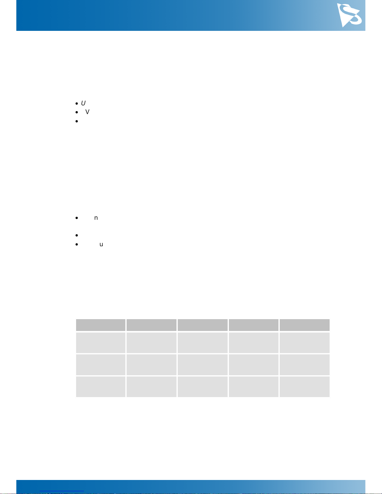
The DMK 33UX183 monochrome camera supports multiple pixel formats with variable
bits-per-pixel settings. The names of the pixel formats and the way to select them
depends on the driver used to control the camera. The following table contains a short
overview of all possible formats followed by a more detailed description.
Pixel Format
Bits Per Pixel
USB3 Vision
UVC
TIS UVC Driver
8-Bit
Monochrome
8
Mono8
Y800
Y800
12-Bit Packed
Monochrome
12
Mono12p
Y12p
Y16
16-Bit Packed
Monochrome
16
Mono16
Y16
Y16
5.1.1.1
8-Bit Monochrome
This format transmits data using one byte for each pixel.
USB3 Vision drivers see this pixel format as Mono8.
Page 14

DMK 33UX183 Technical Reference Manual
14
Camera Controls
UVC drivers see it with the FourCC Y800.
The Device Driver for The Imaging Source USB 33U, 37U and 38U Cameras offers this
pixel format as the Y800 video format.
5.1.1.2
12-Bit Packed Monochrome
This format transmits data using 3 bytes for each pair of 2 consecutive pixels.
USB3 Vision drivers see this pixel format as Mono12p.
UVC drivers see it with the FourCC Y12p.
The Device Driver for The Imaging Source USB 33U, 37U and 38U Cameras offers this
pixel format as the Y16 video format. Since the DMK 33UX183 camera offers both 12bit packed and 16-bit monochrome pixel formats, the driver will use the 12-bit packed
format when the Y16 video format is selected.
5.1.1.3
16-Bit Monochrome
The sensor of the DMK 33UX183 camera is not capable of providing 16-bit data output.
Instead, the pixel data is transmitted in the most significant bits which allows
application programs to ignore the sensor-specific data type, and treat the data as if
the sensor outputs 16 bits.
USB3 Vision drivers see this pixel format as Mono16.
UVC drivers see it with the FourCC Y16.
The Device Driver for The Imaging Source USB 33U, 37U and 38U Cameras offers this
pixel format as the Y16 video format.
5.1.2
Resolution
The DMK 33UX183 allows the user to specify which rectangular region of the image
sensor to read out during camera operation. The size of this rectangle determines the
number of pixels that have to be transferred for each frame and has a significant
influence on the required USB bandwidth.
Lowering the resolution also often allows the image sensor to operate at a higher frame
rate. Changes in the vertical resolution have more effect on the maximum frame rate
than changes in the horizontal direction.
The way the resolution is controlled varies greatly between the driver technology used
to access the camera:
·
When using USB3 Vision, the resolution is controlled through the GenICam features
Width and Height.
·
When using the uvcvideo on Linux, the resolution is selected from a list of fixed
formats. Dynamic frame sizes are not available.
·
When using IC Imaging Control, the resolution is part of the video format, a parameter
that combines pixel format, resolution and readout mode. For more information, refer
Page 15
DMK 33UX183 Technical Reference Manual
15
Camera Controls
to the IC Imaging Control documentation sections on VideoFormat and
VideoFormatDesc.
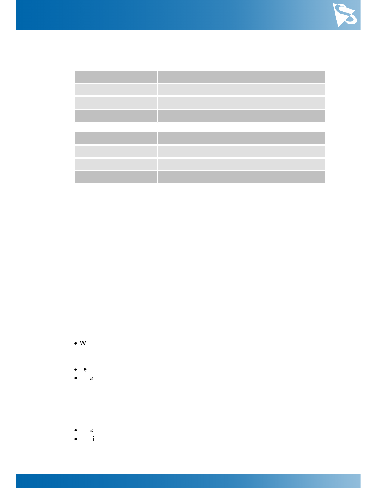
Parameter
Horizontal Resolution
Minimum
256
Maximum
5472
USB3 Vision: GenICam
Width
Parameter
Vertical Resolution
Minimum
4
Maximum
3648
USB3 Vision: GenICam
Height
5.1.3
Readout Modes
The DMK 33UX183 camera offers different sensor readout modes.
By default, the camera outputs all pixels of the image sensor.
In skipping modes, the image sensor regularly skips a number of rows and/or columns
during readout. The resulting output image is smaller but contains the same field of
view than the image produced by default readout mode.
In binning modes, a number of neighboring pixels is merged into one output pixel
during readout. The nature of this merge operation is sensor-specific, most sensors
either add the pixel values or average them.
Generally, binning modes provide better image quality than skipping modes. However,
skipping modes usually provide a higher maximum frame rate.
The way the readout modes are controlled depends greatly upon which driver
technology is used to access the camera:
·
When using USB3 Vision, the readout mode is controlled through the GenICam
features DecimationHorizontal, DecimationVertical, BinningHorizontal
and BinningVertical.
·
Selecting readout modes is currently not supported through UVC in Linux.
·
When using IC Imaging Control, the readout mode is part of the video format - a
parameter that which combines pixel format, resolution and readout mode. For more
information, refer to the IC Imaging Control documentation sections on
VideoFormat and VideoFormatDesc.
The following readout modes are supported:
·
Default
·
Binning 2X
Page 16
DMK 33UX183 Technical Reference Manual
16
Camera Controls
5.1.4
Frame Rate
The frame rate is specified in frames per second and determines the camera's operating
speed.
The way the frame rate is controlled depends greatly upon which driver technology is
used to access the camera:
·
When using USB3 Vision, the frame rate is controlled through the GenICam feature
AcquisitionFrameRate.
·
When using uvcvideo on Linux, the frame rate is selected from a list of available
frame rates.
·
When using IC Imaging Control, the frame rate is selected from a list of available
frame rates through APIs such as Grabber::setFPS or
ICImagingControl.DeviceFrameRate.
The range of available frame rates depends upon other camera settings such as well,
pixel format, resolution and readout modes.
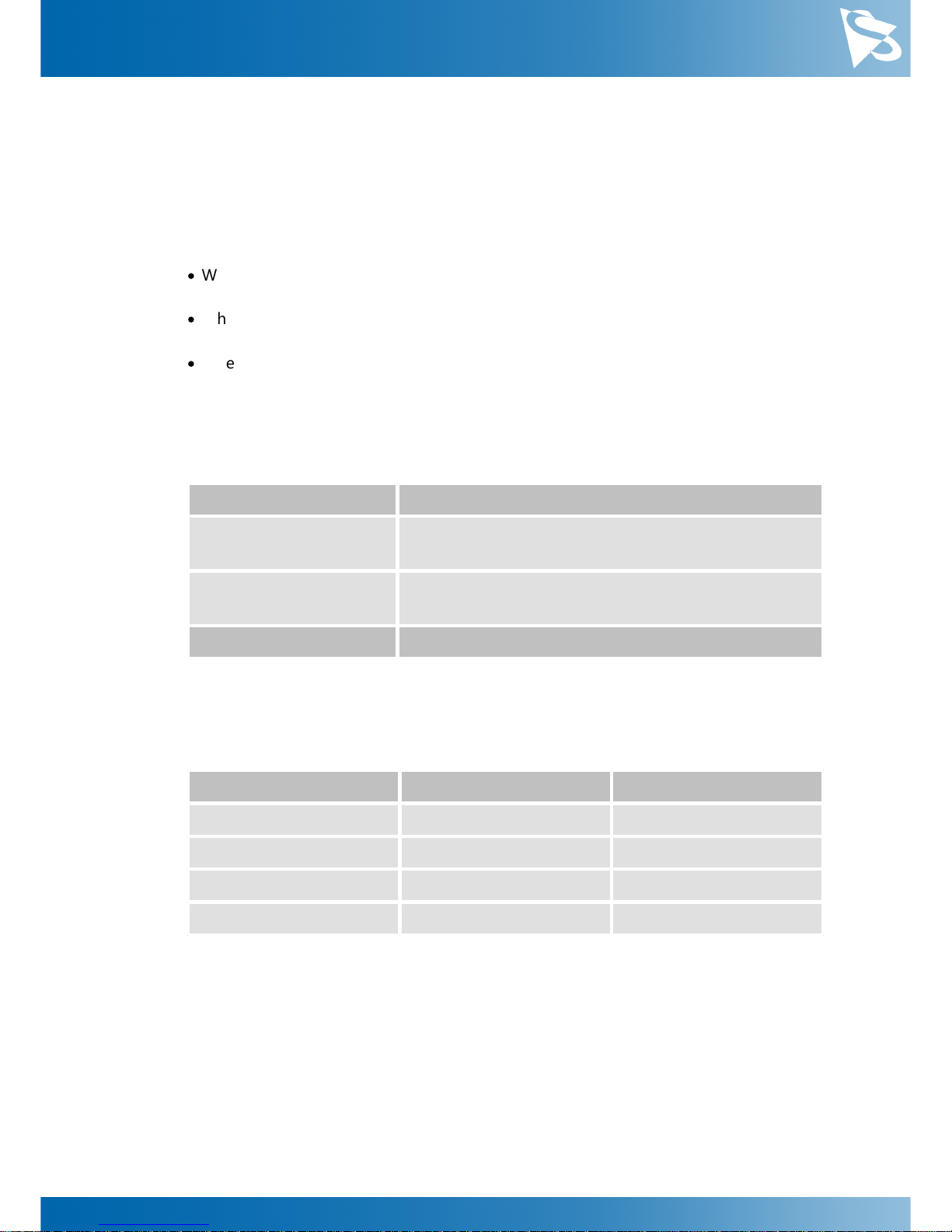
Parameter
Frame Rate
Minimum
Depending on Pixel Format, Resolution, and Readout
Mode
Maximum
Depending on Pixel Format, Resolution, and Readout
Mode
USB3 Vision: GenICam
AcquisitionFrameRate
The following tables show the maximum frame rate for some combinations of pixel
format and resolution.
8-Bit Monochrome
Width
Height
Maximum Frame Rate
5472
3648
18
3840
2160
31
1920
1080
60
640
480
125
12-Bit Packed Monochrome
Page 17

DMK 33UX183 Technical Reference Manual
17
Camera Controls
Width
Height
Maximum Frame Rate
5472
3648
12
3840
2160
20
1920
1080
40
640
480
83
16-Bit Monochrome
Width
Height
Maximum Frame Rate
5472
3648
9
3840
2160
15
1920
1080
30
640
480
62
5.1.5
Partial Scan Offset
If the selected resolution is smaller than the sensor size, the part of the sensor that is
actually read out can be specified by the Partial Scan Offset X and Partial Scan Offset Y
parameters. By default, the camera automatically positions the offsets so that the center
of the sensor is used.
Parameter
Partial Scan Offset X
Minimum
0
Maximum
5216
USB3 Vision: GenICam
OffsetX
Video4Linux2
ROI Offset X
VCD Property
VCDID_PartialScanOffset
\VCDElement_PartialScanOffsetX
Parameter
Partial Scan Offset Y
Minimum
0
Maximum
3644
USB3 Vision: GenICam
OffsetY
Video4Linux2
ROI Offset Y
VCD Property
VCDID_PartialScanOffset
\VCDElement_PartialScanOffsetY
Page 18
DMK 33UX183 Technical Reference Manual
18
Camera Controls
If Partial Scan Offset X or Partial Scan Offset Y is configured to a value that would be
invalid with the current setting of Resolution setting, the camera uses the maximum
possible value.
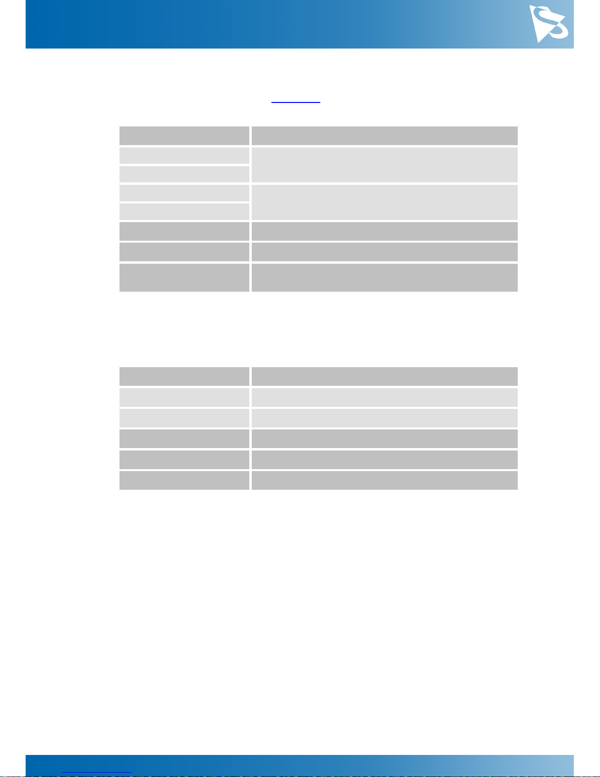
Parameter
Partial Scan Auto Center
On
Automatically configure Partial Scan Offset X/Y so that
the center area of the sensor is read out
True
Off
Control Partial Scan Offset X/Y manually
False
USB3 Vision: GenICam
OffsetAutoCenter
Video4Linux2
ROI Auto Center
VCD Property
VCDID_PartialScanOffset
\VCDElement_PartialScanAutoCenter
5.1.6
Image Flipping
The DMK 33UX183 camera allows for vertical flipping of the image data. The Flip
Vertical parameter can be used to control this sensor feature.
Parameter
Flip Vertical
True
Image data is flipped vertically
False
Image data is not flipped vertically
USB3 Vision: GenICam
ReverseY
Video4Linux2
Flip Vertical
VCD Property
VCDID_FlipVertical\VCDElement_Value
5.2
Image Sensor Control
5.2.1
Exposure Time
The Exposure Time parameter defines the time the camera opens its (electronic) shutter
when it is taking an image.
Page 19
DMK 33UX183 Technical Reference Manual
19
Camera Controls
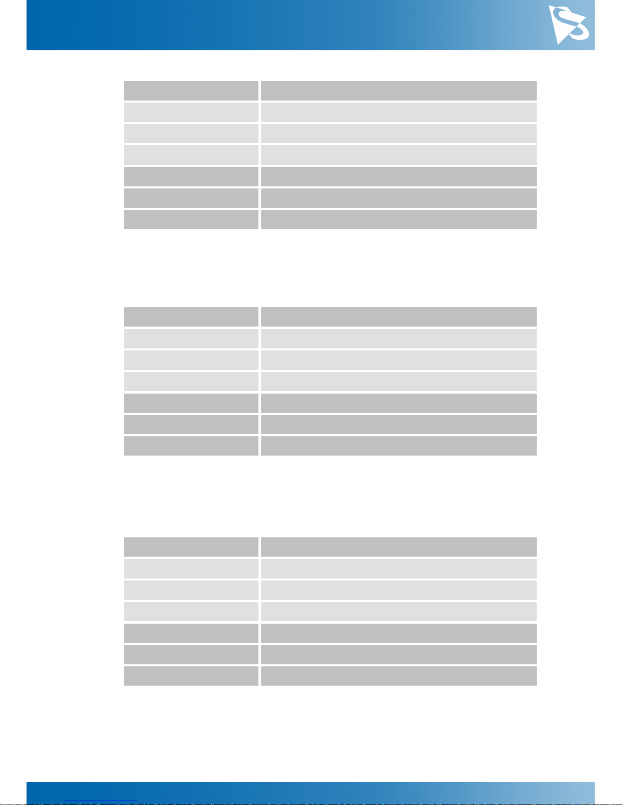
Parameter
Exposure Time
Minimum
50 µs
Maximum
30 s
Default
auto
USB3 Vision: GenICam
ExposureTime
Video4Linux2
Exposure Time (us)
VCD Property
VCDID_Exposure\VCDElement_Value
5.2.2
Gain
The Gain parameter defines the amplification that is applied to the image at sensor
level.
Parameter
Gain
Minimum
0 dB
Maximum
2704 dB
Default
auto
USB3 Vision: GenICam
Gain
Video4Linux2
Gain (db/100)
VCD Property
VCDID_Gain\VCDElement_Value
5.2.3
Black Level
The Black Level parameter defines the lowest possibly intensity value of the image
sensor.
Parameter
Black Level
Minimum
0
Maximum
1023
Default
50
USB3 Vision: GenICam
BlackLevel
Video4Linux2
Brightness
VCD Property
VCDID_Brightness\VCDElement_Value
Page 20
DMK 33UX183 Technical Reference Manual
20
Camera Controls
5.3
Automatic Exposure and Gain Control
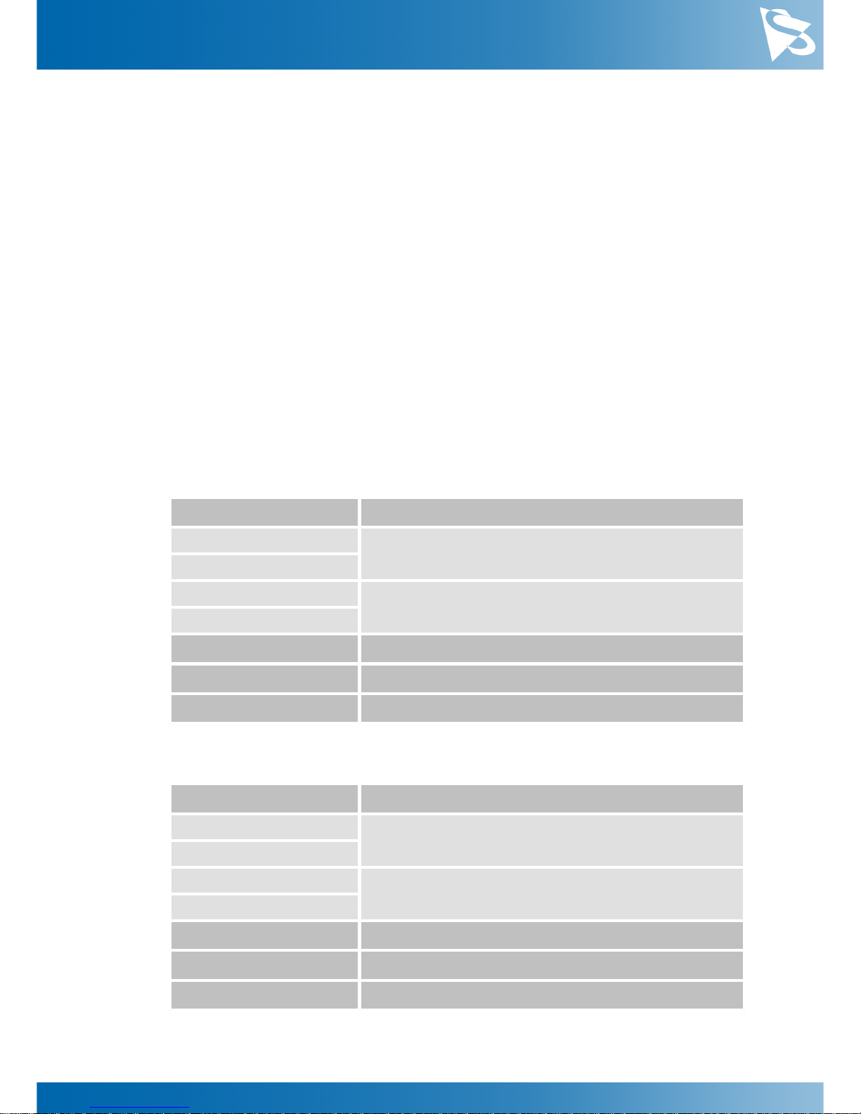
The DMK 33UX183 camera can automatically control gain and exposure time. These
automatic functions are enabled by default.
In order to optimize image parameters, a region of interest can be specified for
automatic functions. Specifying a region of interest enables fine-grained control over
the image area for which the image parameters are optimized. A selection of predefined area presets is available, but the user can also specify the coordinates of a
custom rectangle.
In certain situations, it is desirable to limit the range of the auto-controlled parameters.
For example, one might want to avoid high gain settings in order to keep noise levels
low. Other applications require limiting the maximum exposure time so that
movements do not get blurred. Therefore, the ranges of the gain and exposure
parameter can be limited.
If both auto exposure and auto gain are active, the camera tries to lower the gain value
in order to reduce noise and improve the image quality.
5.3.1
Auto Exposure
Parameter
Auto Exposure
Continuous
Enable Auto Exposure
True
Off
Disable Auto Exposure
False
USB3 Vision: GenICam
ExposureAuto
Video4Linux2
Auto Shutter
VCD Property
VCDID_Exposure\VCDElement_Auto
5.3.2
Auto Gain
Parameter
Auto Gain
Continuous
Enable Auto Gain
True
Off
Disable Auto Gain
False
USB3 Vision: GenICam
GainAuto
Video4Linux2
Auto Gain
VCD Property
VCDID_Gain\VCDElement_Auto
Page 21
DMK 33UX183 Technical Reference Manual
21
Camera Controls
5.3.3
Auto Reference Value
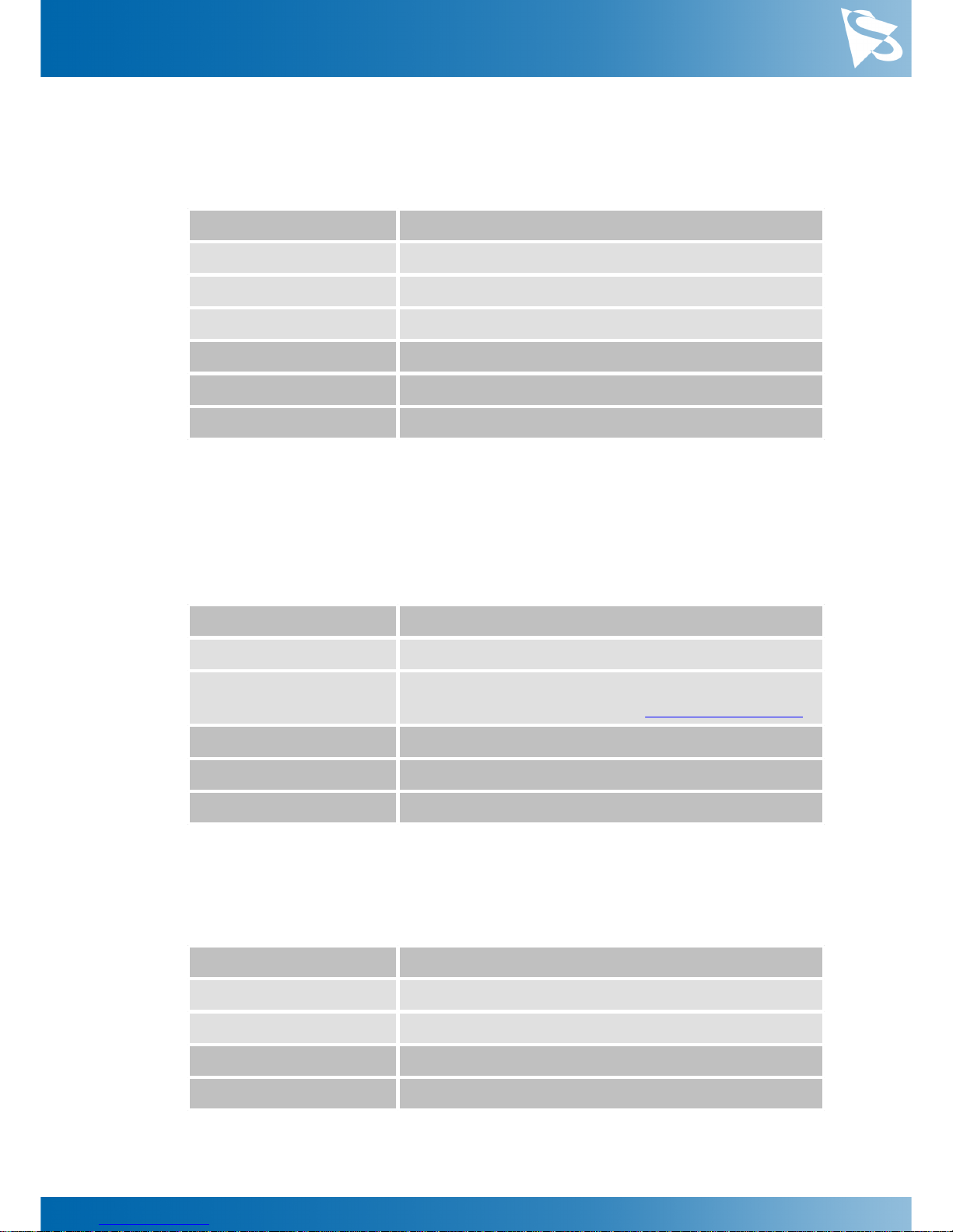
The Auto Reference Value parameter specifies the target brightness for both auto
exposure and auto gain.
Parameter
Auto Reference Value
Minimum
0
Maximum
255
Default
128
USB3 Vision: GenICam
ExposureAutoReference
Video4Linux2
ExposureAutoReference
VCD Property
VCDID_Exposure\VCDElement_AutoReference
5.3.4
Highlight Reduction
Enabling Highlight Reduction lets the auto exposure and auto gain functions reduce
overexposed areas in the output image. This feature is particularly useful when using
10/12/16-bit output images and a tone mapping algorithm in post-processing when
using higher bit depths as the dark areas still contain a lot of useful information.
Parameter
Highlight Reduction
True
Try to reduce overexposed areas
False
Ignore overexposed areas and focus on matching the
image brightness to the selected Auto Reference Value.
USB3 Vision: GenICam
ExposureAutoHighlightReduction
Video4Linux2
Highlight Reduction
VCD Property
VCDID_HighlightReduction\VCDElement_Value
5.3.5
Auto Exposure Limits
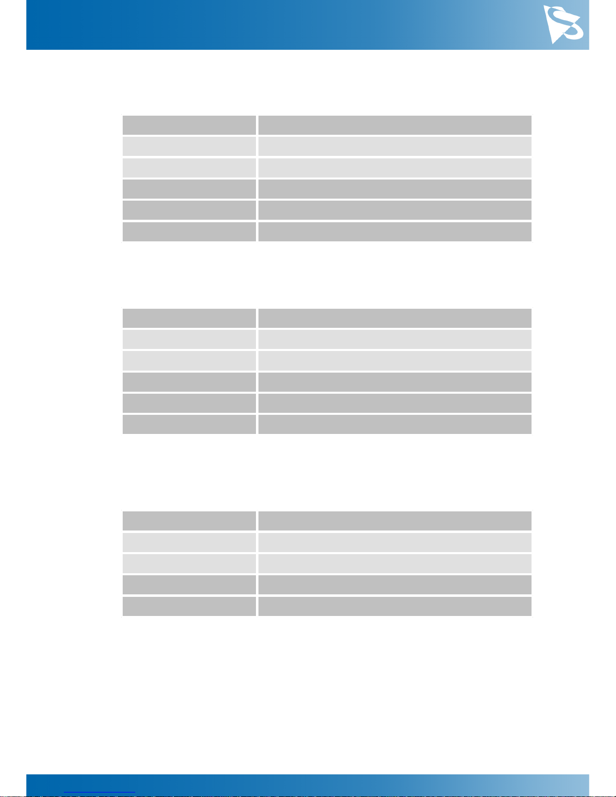
The Auto Exposure Lower Limit parameter determines the minimum possible value that
can be set by the auto exposure algorithm.
Parameter
Auto Exposure Lower Limit
Minimum
50 µs
Maximum
1 s
USB3 Vision: GenICam
ExposureAutoLowerLimit
Video4Linux2
Exposure Auto Lower Limit
Page 22
DMK 33UX183 Technical Reference Manual
22
Camera Controls
The Auto Exposure Upper Limit parameter determines the maximum possible value that
can be set by the auto exposure algorithm.
Parameter
Auto Exposure Upper Limit
Minimum
50 µs
Maximum
1 s
USB3 Vision: GenICam
ExposureAutoUpperLimit
Video4Linux2
Exposure Auto Upper Limit
VCD Property
VCDID_Exposure\VCDElement_AutoMaxValue
If the Auto Exposure Upper Limit Auto parameter is enabled, the value of Auto Exposure
Upper Limit is automatically kept at the maximum possible value for the current frame
rate.
Parameter
Auto Exposure Upper Limit Auto
On
Select Auto Exposure Upper Limit automatically
Off
Let the user control Auto Exposure Upper Limit
USB3 Vision: GenICam
ExposureAutoUpperLimitAuto
UVC
Exposure Auto Upper Limit Auto
Video4Linux2
VCDID_Exposure\VCDElement_AutoMaxValueAuto
5.3.6
Auto Gain Limits
The Auto Gain Lower Limit parameter determines the minimum possible value that can
be set by the auto gain algorithm.
Parameter
Auto Gain Lower Limit
Minimum
0 dB
Maximum
2704 dB
USB3 Vision: GenICam
GainAutoLowerLimit
Video4Linux2
Gain Auto Lower Limit
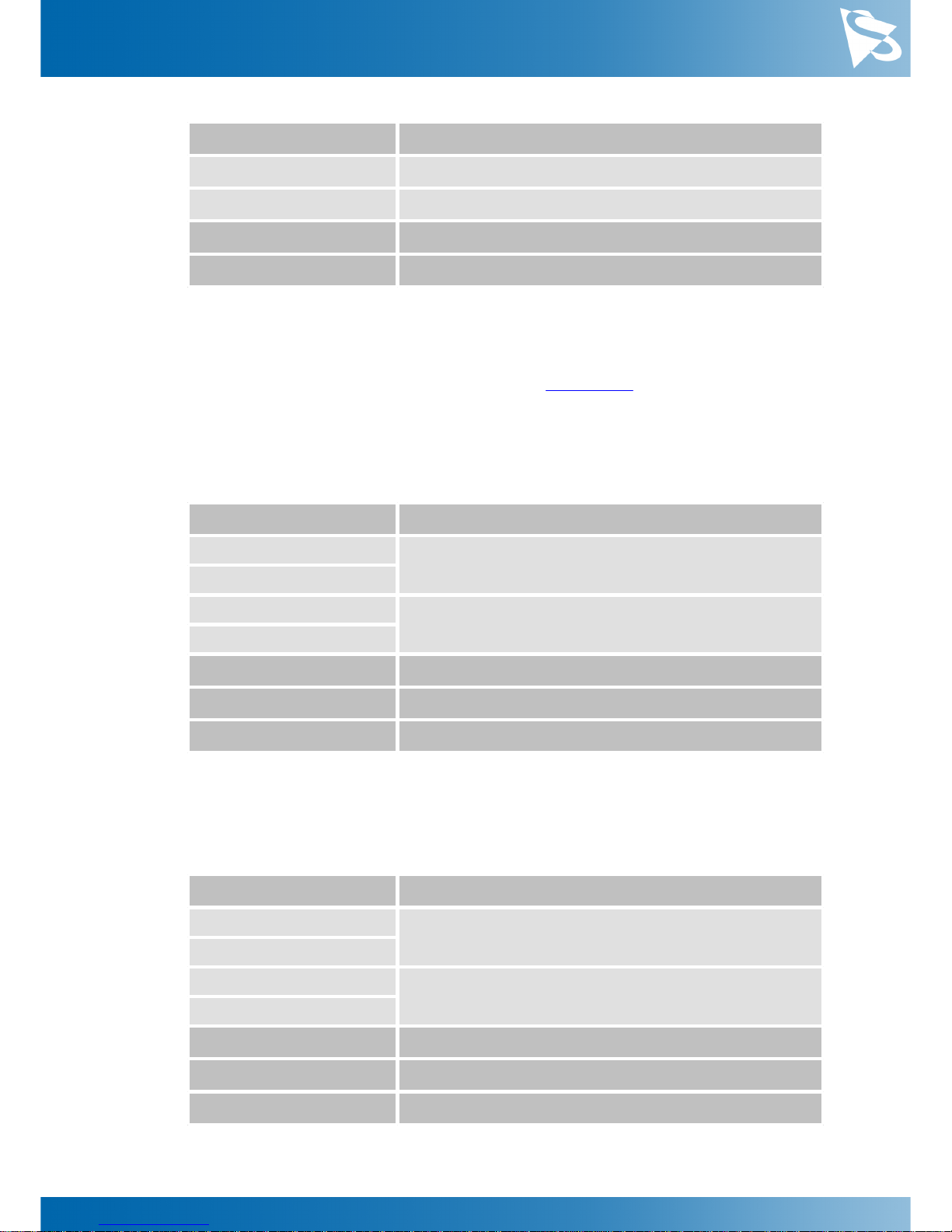
The Auto Gain Upper Limit parameter determines the maximum possible value that can
be set by the auto gain algorithm.
Page 23
DMK 33UX183 Technical Reference Manual
23
Camera Controls
Parameter
Auto Gain Upper Limit
Minimum
0 dB
Maximum
2704 dB
USB3 Vision: GenICam
GainAutoUpperLimit
Video4Linux2
Gain Auto Upper Limit
5.4
Trigger
The trigger mode can be used to take images at very specific points in time which are
specified by an electrical signal connected to the TRIGGER_IN pin of the I/O connector
of the camera.
5.4.1
Trigger Mode
The Trigger Mode parameter enables the trigger mode.
Parameter
Trigger Mode
On
Enable Trigger Mode
True
Off
Disable Trigger Mode
False
USB3 Vision: GenICam
TriggerMode
Video4Linux2
Trigger Mode
VCD Property
VCDID_Trigger\VCDElement_Value
5.4.2
Trigger Polarity
The Trigger Polarity parameter controls whether a trigger event is accepted on the rising
or falling edge of the signal connected to the TRIGGER_IN line.
Parameter
Trigger Polarity
RisingEdge
Accept rising edge as trigger signal
True
FallingEdge
Accept falling edge as trigger signal
False
USB3 Vision: GenICam
TriggerActivation
Video4Linux2
Trigger Polarity
VCD Property
VCDID_Trigger\VCDElement_Polarity
Page 24
DMK 33UX183 Technical Reference Manual
24
Camera Controls
5.4.3
Trigger Operation
The Trigger Operation parameter controls the operation mode of the sensor in trigger
mode.
Rolling shutter sensors can use the Global Reset Release mode when being triggered. In
this mode, the integration time starts simultaneously for all lines. At the end of the
nominal exposure time, the sensor then stops integrating and starts reading out the
lines - as it is typical for a rolling shutter. Therefore, every line has a slightly longer
actual exposure time than the line above it.
Parameter
Trigger Operation
Default
Default mode
GlobalResetRelease
Use Global Reset Release mode
USB3 Vision: GenICam
TriggerOperation
Video4Linux2
Trigger Operation
VCD Property
VCDID_Trigger\VCDElement_TriggerOperation
5.4.4
Software Trigger
The Software Trigger function can be used to simulate a trigger pulse, in turn causing
one image to be exposed and delivered to the host computer.
Parameter
Software Trigger
Execute
Simulate one trigger pulse
USB3 Vision: GenICam
TriggerSoftware
Video4Linux2
Software Trigger
VCD Property
VCDID_Trigger\VCDElement_SoftwareTrigger
5.4.5
Trigger Burst Count
The Trigger Burst Count parameter allows the camera to be configured to take more
than one image per trigger pulse. By default, this parameter is set to 1 so that exactly
one image is acquired. The images are taken as rapidly as possible given current
settings (i.e. as limited by the current exposure time and frame rate settings).
Page 25
DMK 33UX183 Technical Reference Manual
25
Camera Controls
Parameter
Trigger Burst Count
Minimum
1
Maximum
1000
Default
1
USB3 Vision: GenICam
AcquisitionBurstFrameCount
Video4Linux2
Trigger Burst Count
VCD Property
VCDID_Trigger\VCDElement_TriggerBurstCount
5.4.6
Trigger Source
The Trigger Source parameter allows the camera to be configured to only accept trigger
signals from a specified source, e.g. only software trigger.
Parameter
Trigger Source
Any
Allow trigger signals from any source
Line1
Allow only hardware trigger
Software
Allow only software trigger
USB3 Vision: GenICam
TriggerSource
5.4.7
Trigger Overlap
The Trigger Overlap feature gives information on when a new trigger pulse is accepted
in the trigger -> exposure -> readout sequence.
Parameter
Trigger Overlap
Off
The next trigger pulse is only accepted once the previous
frame has been read out from the sensor
Readout
The next trigger pulse is accepted during readout as long
as the remaining readout time is shorter than the
exposure time
USB3 Vision: GenICam
TriggerOverlap
VCD Property
VCDID_Trigger\VCDElement_TriggerOverlap
5.5
Trigger Timing Parameters
The 33U series camera series offers several options for dealing with bad trigger signals.
By using the Debounce Time, Denoise Time and Mask Time parameters, the camera can
be configured to ignore pulses on its TRIGGER_IN line under certain conditions.
Page 26
DMK 33UX183 Technical Reference Manual
26
Camera Controls
Useful values for these parameters are application-specific. They depend on the
expected trigger frequency, the exposure time and assumptions about the input signal
quality.
The default values for all these parameters is 0 µs, assuming perfect signal quality.
5.5.1
Trigger Delay
The Trigger Delay parameter specifies a time for which the camera waits between
receiving a trigger signal and starting the exposure of an image. Simulated trigger
pulses generated through the Software Trigger function are not delayed by this
parameter.
Parameter
Trigger Delay
Minimum
0 s
Maximum
1 s
Default
0 s
USB3 Vision: GenICam
TriggerDelay
Video4Linux2
Trigger Delay
VCD Property
VCDID_Trigger\VCDElement_TriggerDelay
5.5.2
Trigger Debounce Time
The Trigger Debounce Time parameter specifies the time for which the trigger input has
to be low in order for the next trigger signal to be accepted.
Parameter
Trigger Debounce Time
Minimum
0 s
Maximum
1 s
Default
0 s
USB3 Vision: GenICam
TriggerDebouncer
Video4Linux2
Trigger Debounce Time (us)
VCD Property
VCDID_Trigger\VCDElement_TriggerDebouncer
5.5.3
Trigger Mask Time
The Trigger Mask Time parameter specifies the time for which trigger pulses are ignored
after accepting a trigger signal.
Page 27
DMK 33UX183 Technical Reference Manual
27
Camera Controls
Parameter
Trigger Mask Time
Minimum
0 s
Maximum
1 s
Default
0 s
USB3 Vision: GenICam
TriggerMask
Video4Linux2
Trigger Mask Time (us)
VCD Property
VCDID_Trigger\VCDElement_TriggerMask
5.5.4
Trigger Noise Suppression Time
The Trigger Noise Suppression Time parameter specifies the time for which trigger input
has to be active in order to be accepted as a trigger signal.
Parameter
Trigger Noise Suppression Time
Minimum
0 s
Maximum
1 s
Default
0 s
USB3 Vision: GenICam
TriggerDenoise
Video4Linux2
Trigger Noise Suppression Time
VCD Property
VCDID_Trigger\VCDElement_TriggerDenoise
5.6
Digital I/O
The 33U series has one digital input and one digital output. The digital input can be
used as a Trigger input but the current status can also examined directly.
The digital output can be configured as a Strobe output to signal the exact moment
when the image sensor is sensitive to light so that external light sources can be
synchronized to its operation cycle.
5.6.1
General Purpose Input
The General Purpose Input parameter allows the current status of the TRIGGER_IN pin.
Page 28
DMK 33UX183 Technical Reference Manual
28
Camera Controls
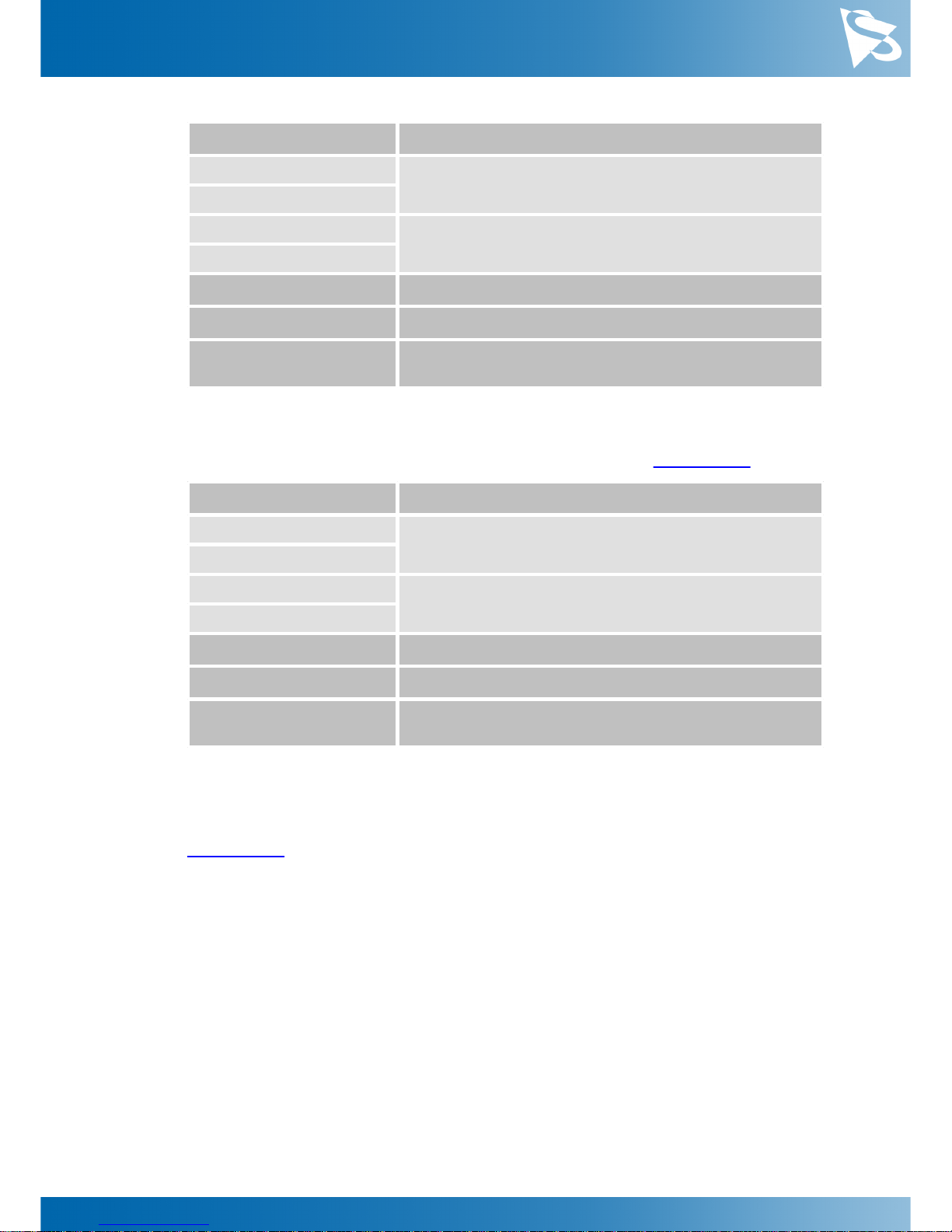
Parameter
General Purpose Input
True
TRIGGER_IN line status is low
1
False
TRIGGER_IN line status is high
0
USB3 Vision: GenICam
GPIn
Video4Linux2
GPIN
VCD Property
VCDID_GPIO\VCDElement_GPIORead
VCDID_GPIO\VCDElement_GPIOIn
5.6.2
General Purpose Output
The General Purpose Output parameter controls the status of the STROBE_OUT pin.
Parameter
General Purpose Output
True
Drive the STROBE_OUT line high
1
False
Drive the STROBE_OUT line low
0
USB3 Vision: GenICam
GPOut
Video4Linux2
GPOUT
VCD Property
VCDID_GPIO\VCDElement_GPIOWrite
VCDID_GPIO\VCDElement_GPIOOut
5.7
Strobe
The strobe function controls the automatic generation of output pulses on the
STROBE_OUT pin which is synchronized to the image sensor's exposure time.
5.7.1
Strobe Enable
The Strobe Enable parameter enables the automatic generation of strobe pulses.
Page 29
DMK 33UX183 Technical Reference Manual
29
Camera Controls
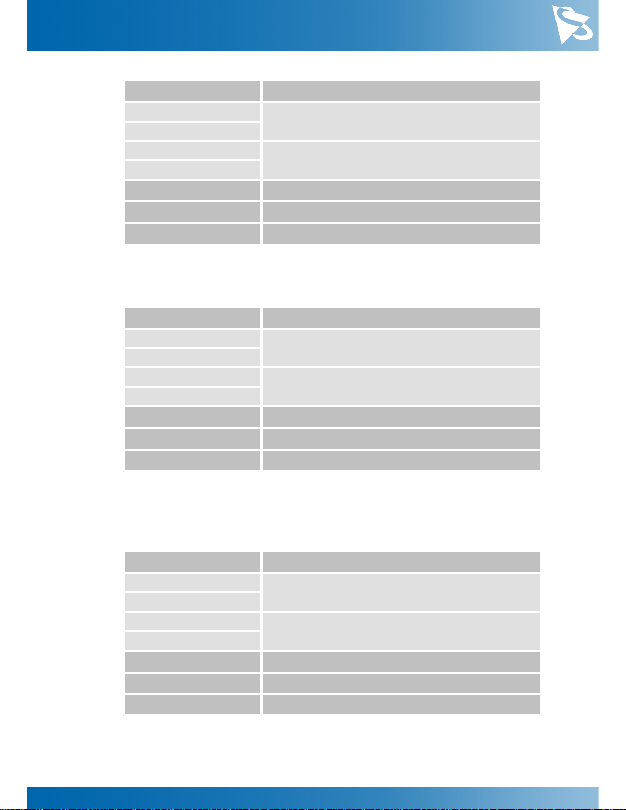
Parameter
Strobe Enable
On
Strobe enabled
True
Off
Strobe disabled
False
USB3 Vision: GenICam
StrobeEnable
Video4Linux2
Strobe Enable
VCD Property
VCDID_Strobe\VCDElement_Value
5.7.2
Strobe Polarity
The Strobe Polarity parameter can be used to invert the strobe pulse output.
Parameter
Strobe Polarity
ActiveHigh
The STROBE_OUT pin is logically high during the
exposure time
True
ActiveLow
The STROBE_OUT pin is logically low during the
exposure time
False
USB3 Vision: GenICam
StrobePolarity
Video4Linux2
Strobe Polarity
VCD Property
VCDID_Strobe\VCDElement_StrobePolarity
5.7.3
Strobe Operation
The Strobe Operation parameter specifies how the length of the strobe pulses are
controlled.
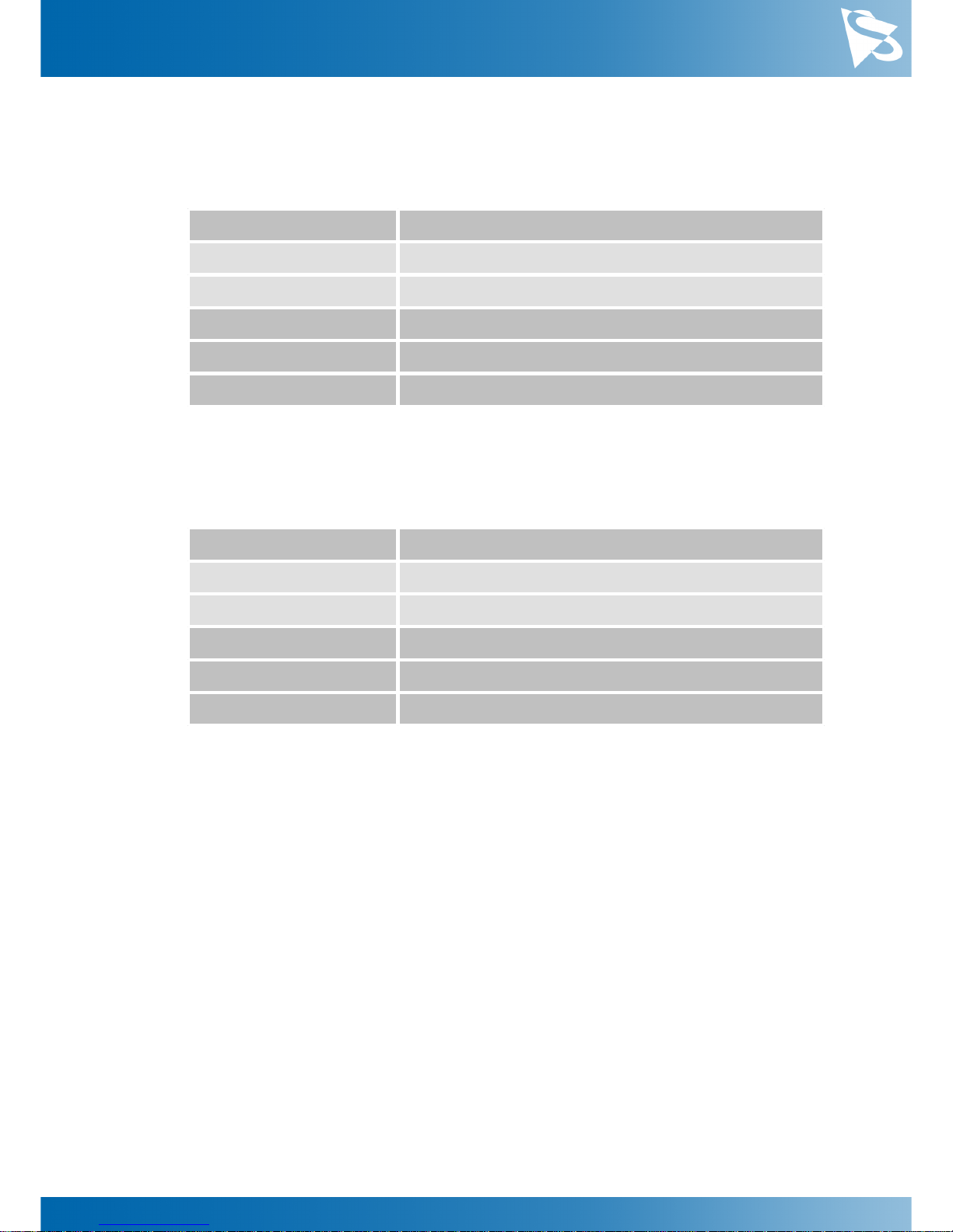
Parameter
Strobe Operation
Exposure
Output pulse duration is equal to the current exposure
time
True
FixedDuration
Output pulse duration is specified by Strobe Duration
False
USB3 Vision: GenICam
StrobeOperation
Video4Linux2
Strobe Exposure
VCD Property
VCDID_Strobe\VCDElement_StrobeMode
Page 30
DMK 33UX183 Technical Reference Manual
30
Camera Controls
5.7.4
Strobe Duration
The Strobe Duration parameter controls the length of the strobe pulses if Strobe
Operation is set to use the fixed duration mode.
Parameter
Strobe Duration
Minimum
0 µs
Maximum
32767 µs
USB3 Vision: GenICam
StrobeDuration
Video4Linux2
Strobe Duration
VCD Property
VCDID_Strobe\VCDElement_StrobeDuration
5.7.5
Strobe Delay
The Strobe Delay parameter can be used to add a small delay between the start of
exposure and the strobe output pulse.
Parameter
Strobe Delay
Minimum
0 µs
Maximum
32767 µs
USB3 Vision: GenICam
StrobeDelay
Video4Linux2
Strobe Delay
VCD Property
VCDID_Strobe\VCDElement_StrobeDelay
5.8
Image Processing
5.8.1
Gamma
The 33U series cameras can perform gamma correction on the image data. If the pixel
format of a color camera is set a YUV mode, gamma correction is applied to the Y
channel. In bayer raw and RGB24 modes, all color channels are subject to the same
gamma correction.
Page 31
DMK 33UX183 Technical Reference Manual
31
Camera Controls
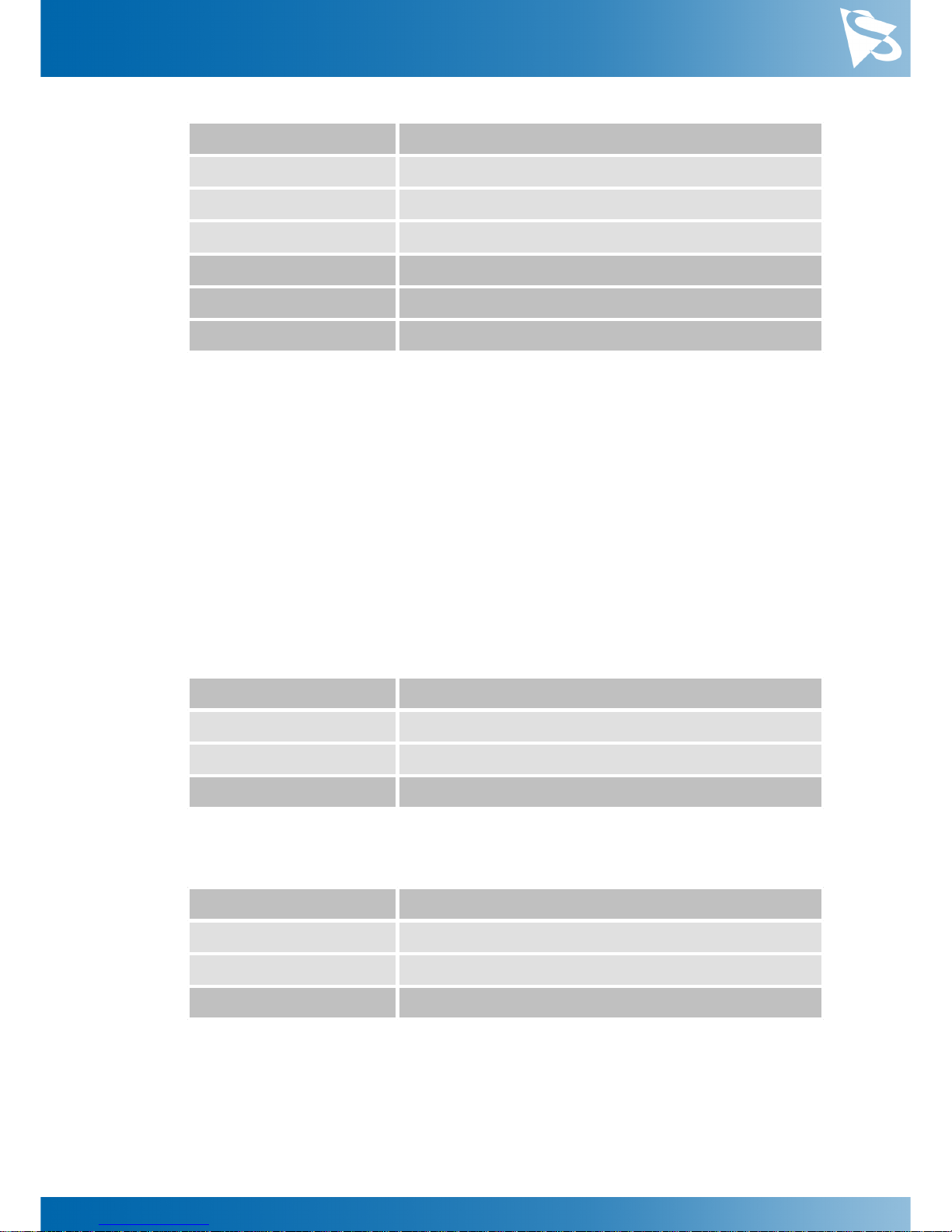
Parameter
Gamma
Minimum
0.01
Maximum
5.0
Default
1.0
USB3 Vision: GenICam
Gamma
Video4Linux2
Gamma
VCD Property
VCDID_Gamma\VCDElement_Value
5.8.2
Lookup Table
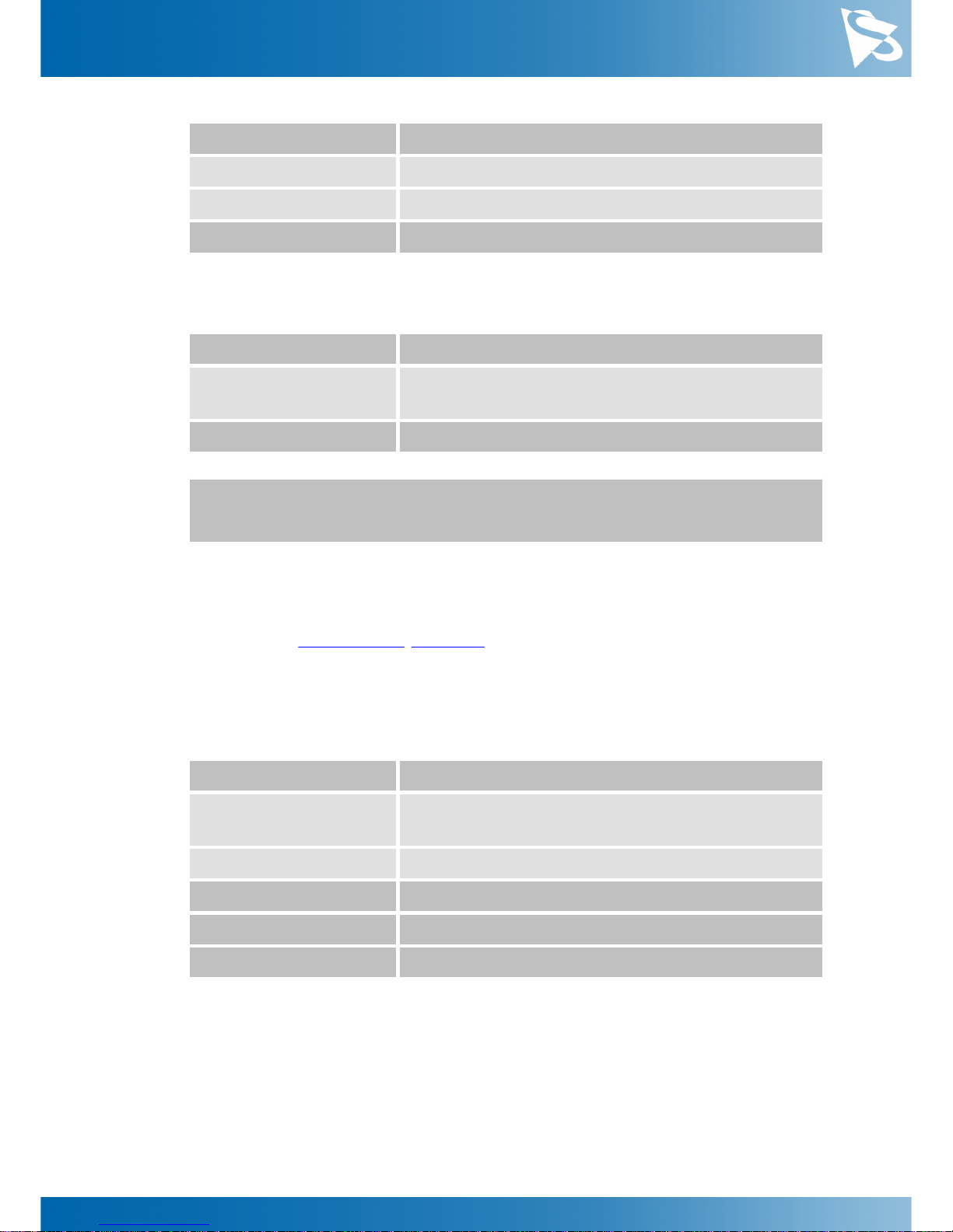
The 33U series allows the user to specify a lookup table (LUT) that can transform pixel
values. This lookup table can be used to perform tasks like histogram equalization
inside the camera.
If the pixel format of a color camera is set to one of the YUV modes, the lookup table is
applied only to the Y channel. In bayer raw and RGB24 modes, all color channels are
subject to the same lookup operation.
The lookup table has 257 16-bit entries. The upper 8 bits of the image data are used to
select the appropriate entry in the lookup table, while the remaining bits are used to
interpolate between the selected entry and one of its neighbors.
The LUT Enable feature enables the lookup table.
Parameter
LUT Enable
True
Enable lookup table operation
False
Disable lookup table operation
USB3 Vision: GenICam
LUTEnable
The lookup table values can be programmed using the LUT Index and LUT Value
features.
Parameter
LUT Index
Minimum
0
Maximum
256
USB3 Vision: GenICam
LUTIndex
Page 32
DMK 33UX183 Technical Reference Manual
32
Camera Controls
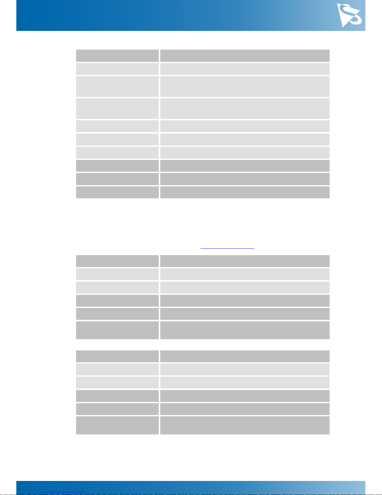
Parameter
LUT Value
Minimum
0
Maximum
65535
USB3 Vision: GenICam
LUTValue
The whole lookup table can be quickly reprogrammed through the LUT Value All
feature.
Parameter
LUT Value All
Value
1028 bytes of memory containing 257 LUT entries. Each
16-bit LUT entry is aligned on a 32-bit boundary
USB3 Vision: GenICam
LUTValueAll
Important: Since gamma correction is implemented using the same hardware as the
lookup table, gamma correction is disabled when the lookup table is enabled.
5.9
Region of Interest for Auto Functions
The 33U series cameras allow for the setting of a region of interest that is used while
controlling the Auto Exposure, Auto Gain and Auto White Balance functions.
5.9.1
Auto Functions ROI Enable
The Auto Functions ROI Enable parameter allows for the use of a region of interest for
auto functions.
Parameter
Auto Functions ROI Enable
True
Auto functions only take a specified part of the image
into account
False
Auto functions look at the whole image
USB3 Vision: GenICam
AutoFunctionsROIEnable
Video4Linux2
Auto Functions ROI Enable
VCD Property
VCDID_AutoRoi\VCDElement_Value
5.9.2
Auto Functions ROI Preset
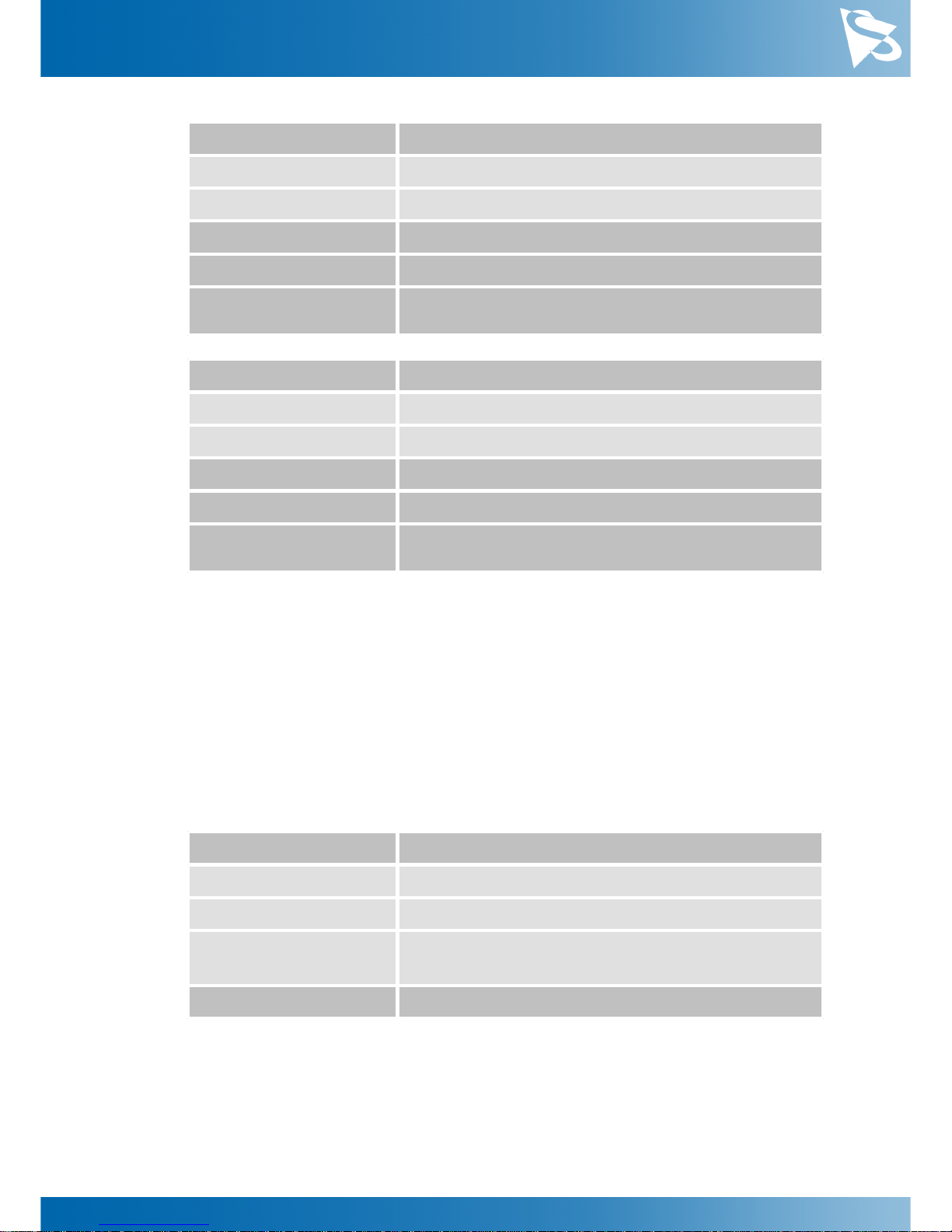
The Auto Functions ROI Preset parameter lets the user select from a list of ROI presets.
Page 33
DMK 33UX183 Technical Reference Manual
33
Camera Controls
Parameter
Auto Functions ROI Preset
Full Sensor
Select the full output image
Center 50%
Select a rectangular area in the center of the output
image
Center 25%
Select a small rectangular area in the center of the
output image
Bottom Half
Select the bottom half of the output image
Top Half
Select the top half of the output image
Custom Rectangle
Select a custom rectangle for fine-grained control
USB3 Vision: GenICam
AutoFunctionsROIPreset
Video4Linux2
Auto Functions ROI Preset
VCD Property
VCDID_AutoRoi\VCDElement_AutoRoiPreset
5.9.3
Auto Functions ROI Custom Rectangle
When Auto Functions ROI Preset is set to Custom Rectangle, the user can manually set
the position and size of the region of interest. The coordinates are relative to the origin
of the current video format as specified by Partial Scan Offset.
Parameter
Auto Functions ROI Left
Minimum
0
Maximum
2576
USB3 Vision: GenICam
AutoFunctionsROILeft
Video4Linux2
Auto Functions ROI Left
VCD Property
VCDID_AutoRoi
\VCDElement_AutoRoiLeftRelative
Parameter
Auto Functions ROI Top
Minimum
0
Maximum
2032
USB3 Vision: GenICam
AutoFunctionsROITop
Video4Linux2
Auto Functions ROI Top
VCD Property
VCDID_AutoRoi
\VCDElement_AutoRoiTopRelative
Page 34
DMK 33UX183 Technical Reference Manual
34
Camera Controls
Parameter
Auto Functions ROI Width
Minimum
16
Maximum
2592
USB3 Vision: GenICam
AutoFunctionsROIWidth
Video4Linux2
Auto Functions ROI Width
VCD Property
VCDID_AutoRoi
\VCDElement_AutoRoiWidthRelative
Parameter
Auto Functions ROI Height
Minimum
16
Maximum
2048
USB3 Vision: GenICam
AutoFunctionsROIHeight
Video4Linux2
Auto Functions ROI Height
VCD Property
VCDID_AutoRoi
\VCDElement_AutoRoiHeightRelative
5.10
User Sets
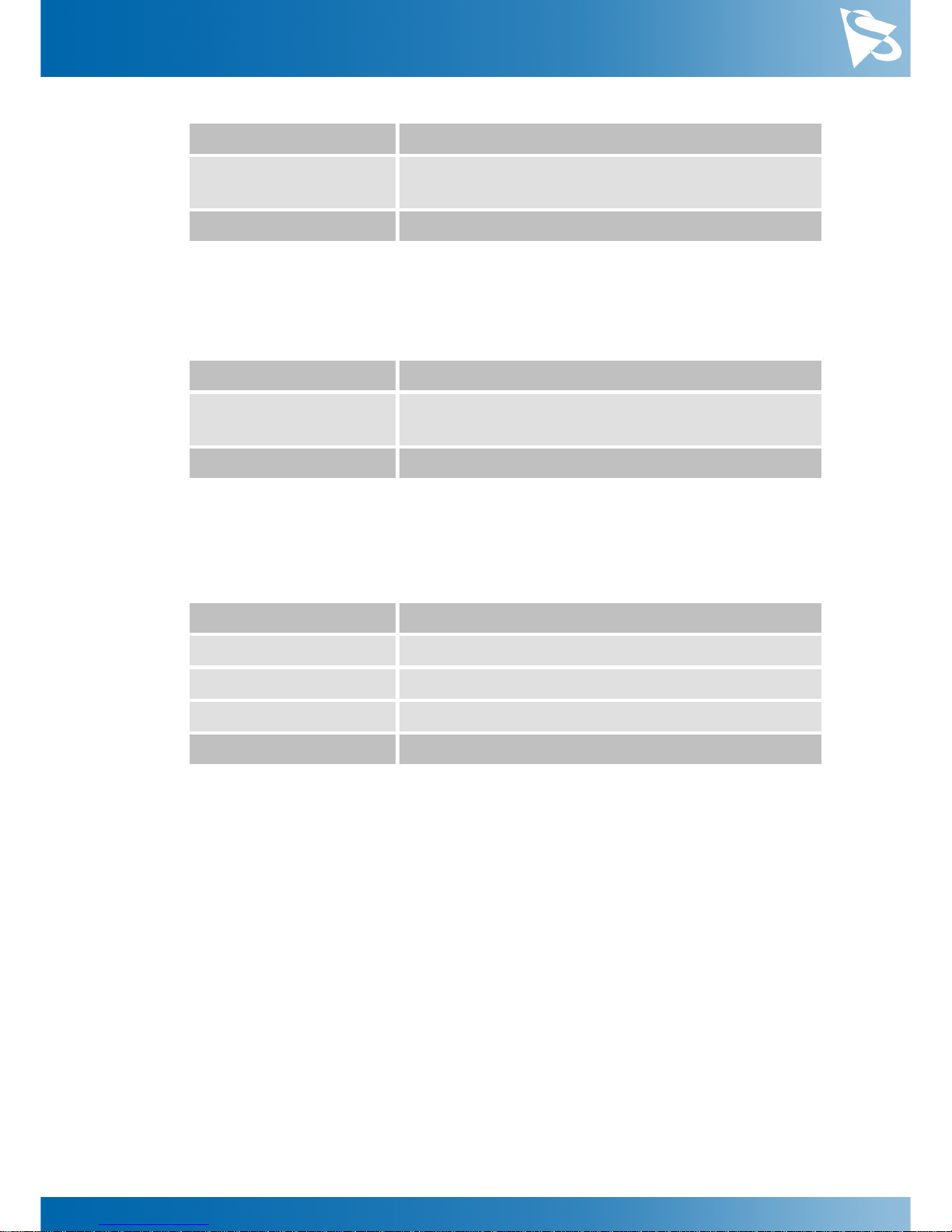
The 33U series cameras can store their complete configuration into built-in non-volatile
memory. The camera configuration can be saved into and restored from one of two
available memory slots upon user's request. Additionally, the camera can be configured
to load one of the user's camera configurations at startup.
5.10.1
User Set Selector
The User Set Selector parameter selects the memory slot on which consecutive load and
save commands are executed.
Parameter
User Set Selector
UserSet1
First of the two memory slots for user configurations
UserSet2
Second of the two memory slots for user configurations
Default
A special memory slot that always contains the camera's
factory default configuration. It cannot be overwritten
USB3 Vision: GenICam
UserSetSelector
5.10.2
Load User Set
By using the Load User Set command, the user can restore the camera configuration
from the memory slot selected by User Set Selector.
Page 35
DMK 33UX183 Technical Reference Manual
35
Camera Controls
Parameter
Load User Set
Execute
Restore the camera configuration from the memory slot
specified by User Set Selector
USB3 Vision: GenICam
UserSetLoad
5.10.3
Save User Set
By using the Save User Set command, the user can save the camera configuration into
the memory slot selected by User Set Selector.
Parameter
Save User Set
Execute
Save the current camera configuration into the memory
slot specified by User Set Selector
USB3 Vision: GenICam
UserSetSave
5.10.4
Default User Set
The Default User Set parameter controls the camera's startup behavior. It selects which
memory slot is used for device initialization when the camera is powered up.
Parameter
Default User Set
UserSet1
Load configuration from the first memory slot
UserSet2
Load configuration from the second memory slot
Default
Load factory default configuration
USB3 Vision: GenICam
UserSetDefault
Page 36

DMK 33UX183 Technical Reference Manual
36
Revision History
6 Revision History
Date
Version
Description
2018/10/15
Initial release of this document
Page 37

DMK 33UX183 Technical Reference Manual
37
DMK 33UX183 Technical Reference Manual
All product and company na mes in this document may be tra demarks and tradena mes of their respective
owners and a re he reby acknowl edged.
The Ima ging Source Europe GmbH cannot and does not take any responsibility or liability for any information
contained in thi s document. The s ource code pres ente d in thi s document is exclusively us ed for di dactic
purposes . The Ima ging Source does not assume a ny kind of wa rranty expres sed or implied, resulting from the
us e of the conte nt of this docume nt or the s ource code .
The Ima ging Source Company res erves the right to ma ke cha nges i n specifica tions , function or design a t any
time a nd without prior notice.
Last upda te: November 2018
© 2018 The Ima ging Source
All rights reserved. Repri nt, also in parts, onl y all owed with permiss ion of The Imagi ng Source Europe GmbH.
All weights and di mens ions are a pproximate. Unl ess otherwi se spe cified, the lenses s hown in the context of
cameras a re not shipped wi th the se ca meras .
Headquarters:
The Imaging Source Europe GmbH
Überseetor 18, D-28217 Bremen, Germany
Phone: +49 421 33591-0
North & South America:
The Imaging Source, LLC
6926 Shannon Willow Rd, S 400, Charlotte, NC 28226, USA
Phone: +1 704-370-0110
Asia Pacific:
The Imaging Source Asia Co., Ltd.
2F., No.8, Xinhu 1st Road
Taipei City 114, Neihu District, Taiwan
Phone: +886 2-2792-3153
www.theimagingsource.com
 Loading...