

Imagine communications Selenio VMG-14+ Hardware Setup Manual

HardwareSetupGuide
TM
Selenio
01‐Jun‐2015
VMG‐14+
RevisionA

SelenioTM VMG-14+ Hardware Setup Guide
Document part number: 250-0350-01 Rev A
Printed 6/1/15
PublicationInformation
Copyright 2005-2015 Imagine Communications Corp. Proprietary and Confidential.
This material is protected by the copyright laws of the United States and other countries. No part of this document may be
reproduced, distributed, or altered in any form, by any means, by any entity nor may it be used to make any derivative work
(such as translation, transformation, or adaptation) except in accordance with applicable agreements, contracts, or
licensing, without the express written consent of Imagine Communications. All other uses are illegal.
Notice
This publication is designed to assist in the use of the product as it exists on the date of publication of this manual, and may
not reflect the product at the current time or an unknown time in the future. This publication does not in any way warrant
description accuracy or guarantee the use for the product to which it refers. Imagine Communications reserves the right,
without notice to make such changes in equipment, design, specifications, components, or documentation as progress may
warrant to improve the performance of the product.
Trademarks
SelenioTM and TelurioTM are trademarks of Imagine Communications. Microsoft® and Windows® are registered
trademarks of Microsoft Corporation. All other trademarks and trade names are the property of their respective companies.
Patents
The products described herein are covered by one or more U.S. and foreign patents pending.
U.S. Patents: 6,996,129; 7,046,677; 7,818,355; 8,180,920. Other US and foreign patents pending.
ContactInformation
Imagine Communications has office locations around the world. For domestic and international location and contact
information see: http://www.imaginecommunications.com/contact-us/
SupportContactInformation
For domestic and international support of Selenio VMG, Selenio BNP, Selenio SEP, Selenio MMC, Selenio TAT, Telurio
Packager, Telurio Recording Manager, and Telurio AIM products, contact:
Support Contacts: support@rgbnetworks.com
For domestic and international support of all other Imagine Communications' products not mentioned above, contact:
Support Contacts: http://www.imaginecommunications.com/services/technical-support/
http://www.rgbnetworks.com/support/rgb-customer-portal.php
1.877.RGB.NETW // (1.877.742.6389) - Inside North America
+1.408.701.2800 - Outside North America
SelenioTM VMG-14+ Hardware Setup Guide 2
DocumentChangeHistory
SelenioTM VMG-14+ Hardware Setup Guide Document History
Part Number Software Version Release Date Changes
250-0350-01 Rev A N/A 06/01/2015 • Updated graphics and verbiage to Imagine
Communications branding
250-0248-01 Rev A N/A 12/19/13 • Recommended Ethernet cable routing
information, and doc maintenance.
• Updates to Initialization chapter, to incorporate
current Element Manager screens.
250-0211-01 Rev A N/A 6/15/13 • Add NPM2, TCM2, TCM2+
• Add new DC PEM Terminal Block Cover.
250-0177-01 Rev A Release 3.1.3 11/15/12 • Updated hardware: two fan trays.
• Correct numbering for SCMs and AC PSUs.
250-0137-01 Rev A Release 3.1 11/30/11 New Product
SelenioTM VMG-14+ Hardware Setup Guide 3

TableofContents
Publication Information . . . . . . . . . . . . . . . . . . . . . . . . . . . . . . . . . . . . . . . . . . . . . . . . . . . . . . 2
Notice . . . . . . . . . . . . . . . . . . . . . . . . . . . . . . . . . . . . . . . . . . . . . . . . . . . . . . . . . . . . . . . . . . . 2
Trademarks . . . . . . . . . . . . . . . . . . . . . . . . . . . . . . . . . . . . . . . . . . . . . . . . . . . . . . . . . . . . . . . 2
Patents. . . . . . . . . . . . . . . . . . . . . . . . . . . . . . . . . . . . . . . . . . . . . . . . . . . . . . . . . . . . . . . . . . . 2
Contact Information . . . . . . . . . . . . . . . . . . . . . . . . . . . . . . . . . . . . . . . . . . . . . . . . . . . . . . . . . 2
Support Contact Information . . . . . . . . . . . . . . . . . . . . . . . . . . . . . . . . . . . . . . . . . . . . . . . . . . 2
Chapter 1: Introduction. . . . . . . . . . . . . . . . . . . . . . . . . . . . . . . . . . . . . . . . . . . . . . . . . . . . . . . . . . . . . . . . . . 9
Document Organization. . . . . . . . . . . . . . . . . . . . . . . . . . . . . . . . . . . . . . . . . . . . . . . . . . . . . . 9
Document Audience . . . . . . . . . . . . . . . . . . . . . . . . . . . . . . . . . . . . . . . . . . . . . . . . . . . . . . . . 9
Related Documentation . . . . . . . . . . . . . . . . . . . . . . . . . . . . . . . . . . . . . . . . . . . . . . . . . . . . . 10
Document Conventions . . . . . . . . . . . . . . . . . . . . . . . . . . . . . . . . . . . . . . . . . . . . . . . . . . . . . 10
Graphics . . . . . . . . . . . . . . . . . . . . . . . . . . . . . . . . . . . . . . . . . . . . . . . . . . . . . . . . . . . . . . . . .11
Technical Assistance . . . . . . . . . . . . . . . . . . . . . . . . . . . . . . . . . . . . . . . . . . . . . . . . . . . . . . . .11
Chapter 2: Overview . . . . . . . . . . . . . . . . . . . . . . . . . . . . . . . . . . . . . . . . . . . . . . . . . . . . . . . . . . . . . . . . . . . 12
In This Chapter: . . . . . . . . . . . . . . . . . . . . . . . . . . . . . . . . . . . . . . . . . . . . . . . . . . . . . . . . . . . 13
Product Features . . . . . . . . . . . . . . . . . . . . . . . . . . . . . . . . . . . . . . . . . . . . . . . . . . . . . . . . . . 13
VMG-14+ Chassis and Components . . . . . . . . . . . . . . . . . . . . . . . . . . . . . . . . . . . . . . . . . . . 14
Chassis Front . . . . . . . . . . . . . . . . . . . . . . . . . . . . . . . . . . . . . . . . . . . . . . . . . . . . . . . . . 15
Chassis Rear. . . . . . . . . . . . . . . . . . . . . . . . . . . . . . . . . . . . . . . . . . . . . . . . . . . . . . . . . . 17
Basic Chassis Populations . . . . . . . . . . . . . . . . . . . . . . . . . . . . . . . . . . . . . . . . . . . . . . . 18
Shelf Control Managers . . . . . . . . . . . . . . . . . . . . . . . . . . . . . . . . . . . . . . . . . . . . . . . . . 19
Fan Trays . . . . . . . . . . . . . . . . . . . . . . . . . . . . . . . . . . . . . . . . . . . . . . . . . . . . . . . . . . . . 21
Fan Filter Tray. . . . . . . . . . . . . . . . . . . . . . . . . . . . . . . . . . . . . . . . . . . . . . . . . . . . . . . . . 22
Network Processor Modules . . . . . . . . . . . . . . . . . . . . . . . . . . . . . . . . . . . . . . . . . . . . . . . . . 23
NPM and NPM2 Interfaces . . . . . . . . . . . . . . . . . . . . . . . . . . . . . . . . . . . . . . . . . . . . . . . 24
NPM and NPM2 LEDs . . . . . . . . . . . . . . . . . . . . . . . . . . . . . . . . . . . . . . . . . . . . . . . . . . 24
NPM and NPM2 Management and Serial Ports . . . . . . . . . . . . . . . . . . . . . . . . . . . . . . . 25
VMG-14+ System Modules . . . . . . . . . . . . . . . . . . . . . . . . . . . . . . . . . . . . . . . . . . . . . . . . . . 26
Video Processor Module . . . . . . . . . . . . . . . . . . . . . . . . . . . . . . . . . . . . . . . . . . . . . . . . . 27
Transcoding Modules . . . . . . . . . . . . . . . . . . . . . . . . . . . . . . . . . . . . . . . . . . . . . . . . . . . 28
Application Media Processor. . . . . . . . . . . . . . . . . . . . . . . . . . . . . . . . . . . . . . . . . . . . . . 29
System Power . . . . . . . . . . . . . . . . . . . . . . . . . . . . . . . . . . . . . . . . . . . . . . . . . . . . . . . . . . . . 30
AC System Power . . . . . . . . . . . . . . . . . . . . . . . . . . . . . . . . . . . . . . . . . . . . . . . . . . . . . . 30
DC System Power. . . . . . . . . . . . . . . . . . . . . . . . . . . . . . . . . . . . . . . . . . . . . . . . . . . . . . 32
Cable Management . . . . . . . . . . . . . . . . . . . . . . . . . . . . . . . . . . . . . . . . . . . . . . . . . . . . . . . . 33
Filler Panels. . . . . . . . . . . . . . . . . . . . . . . . . . . . . . . . . . . . . . . . . . . . . . . . . . . . . . . . . . . . . . 34
Chapter 3: Physical Installation . . . . . . . . . . . . . . . . . . . . . . . . . . . . . . . . . . . . . . . . . . . . . . . . . . . . . . . . . . 36
In This Chapter: . . . . . . . . . . . . . . . . . . . . . . . . . . . . . . . . . . . . . . . . . . . . . . . . . . . . . . . . . . . 36
Site Preparation. . . . . . . . . . . . . . . . . . . . . . . . . . . . . . . . . . . . . . . . . . . . . . . . . . . . . . . . . . . 36
Tools and Equipment. . . . . . . . . . . . . . . . . . . . . . . . . . . . . . . . . . . . . . . . . . . . . . . . . . . . 36
SelenioTM VMG-14+ Hardware Setup Guide 4

Gen2 Release 1.4.0
Site Equipment . . . . . . . . . . . . . . . . . . . . . . . . . . . . . . . . . . . . . . . . . . . . . . . . . . . . . . . . 36
Personnel . . . . . . . . . . . . . . . . . . . . . . . . . . . . . . . . . . . . . . . . . . . . . . . . . . . . . . . . . . . . 37
Site Space Requirements . . . . . . . . . . . . . . . . . . . . . . . . . . . . . . . . . . . . . . . . . . . . . . . . 37
Rack Requirements. . . . . . . . . . . . . . . . . . . . . . . . . . . . . . . . . . . . . . . . . . . . . . . . . . . . . 37
Rack Allocation . . . . . . . . . . . . . . . . . . . . . . . . . . . . . . . . . . . . . . . . . . . . . . . . . . . . . . . . 38
Power Connectivity . . . . . . . . . . . . . . . . . . . . . . . . . . . . . . . . . . . . . . . . . . . . . . . . . . . . . 38
Electrostatic Discharge (ESD) Prevention. . . . . . . . . . . . . . . . . . . . . . . . . . . . . . . . . . . . . . . 39
Unpacking and Inspection . . . . . . . . . . . . . . . . . . . . . . . . . . . . . . . . . . . . . . . . . . . . . . . . . . . 39
Inspect Contents . . . . . . . . . . . . . . . . . . . . . . . . . . . . . . . . . . . . . . . . . . . . . . . . . . . . . . . 40
Verify Receipt . . . . . . . . . . . . . . . . . . . . . . . . . . . . . . . . . . . . . . . . . . . . . . . . . . . . . . . . . 40
Installation Instructions . . . . . . . . . . . . . . . . . . . . . . . . . . . . . . . . . . . . . . . . . . . . . . . . . . . . . 40
Use ESD Protection . . . . . . . . . . . . . . . . . . . . . . . . . . . . . . . . . . . . . . . . . . . . . . . . . . . . 41
Installing the Chassis at the Operations Rack . . . . . . . . . . . . . . . . . . . . . . . . . . . . . . . . 41
Inserting VMG Modules—New System. . . . . . . . . . . . . . . . . . . . . . . . . . . . . . . . . . . . . . 41
Preparing the Power Supply (For DC) . . . . . . . . . . . . . . . . . . . . . . . . . . . . . . . . . . . . . . 42
Preparing the Power Supply (for AC) . . . . . . . . . . . . . . . . . . . . . . . . . . . . . . . . . . . . . . . 44
Loading the Application Modules . . . . . . . . . . . . . . . . . . . . . . . . . . . . . . . . . . . . . . . . . . 47
AMP-to-NPM Cabling . . . . . . . . . . . . . . . . . . . . . . . . . . . . . . . . . . . . . . . . . . . . . . . . . . . 49
Double-Checking the Physical Installation . . . . . . . . . . . . . . . . . . . . . . . . . . . . . . . . . . . 50
Power Up and Verify . . . . . . . . . . . . . . . . . . . . . . . . . . . . . . . . . . . . . . . . . . . . . . . . . . . . 50
System Initialization Preparation . . . . . . . . . . . . . . . . . . . . . . . . . . . . . . . . . . . . . . . . . . . . . . 51
Required equipment . . . . . . . . . . . . . . . . . . . . . . . . . . . . . . . . . . . . . . . . . . . . . . . . . . . . 51
Steps . . . . . . . . . . . . . . . . . . . . . . . . . . . . . . . . . . . . . . . . . . . . . . . . . . . . . . . . . . . . . . . . 51
Chapter 4: Initial Configuration . . . . . . . . . . . . . . . . . . . . . . . . . . . . . . . . . . . . . . . . . . . . . . . . . . . . . . . . . . 52
In This Chapter: . . . . . . . . . . . . . . . . . . . . . . . . . . . . . . . . . . . . . . . . . . . . . . . . . . . . . . . . . . . 52
Selenio VMG Physical and Virtual IP Addresses. . . . . . . . . . . . . . . . . . . . . . . . . . . . . . . . . . 52
Prerequisites . . . . . . . . . . . . . . . . . . . . . . . . . . . . . . . . . . . . . . . . . . . . . . . . . . . . . . . . . . . . . 53
Using TCON (Temporary Console) to Set Initial Configuration . . . . . . . . . . . . . . . . . . . . . . . 53
The TCON Main Menu . . . . . . . . . . . . . . . . . . . . . . . . . . . . . . . . . . . . . . . . . . . . . . . . . . 54
Viewing Current Configuration . . . . . . . . . . . . . . . . . . . . . . . . . . . . . . . . . . . . . . . . . . . . 54
Setting Network Addresses for the NPM. . . . . . . . . . . . . . . . . . . . . . . . . . . . . . . . . . . . . 55
Verifying Gateway Connectivity. . . . . . . . . . . . . . . . . . . . . . . . . . . . . . . . . . . . . . . . . . . . 55
Viewing VMG Build Information . . . . . . . . . . . . . . . . . . . . . . . . . . . . . . . . . . . . . . . . . . . 56
Using Element Manager to Finalize Initial Configuration. . . . . . . . . . . . . . . . . . . . . . . . . . . . 56
Chapter 5: Troubleshooting and Maintenance . . . . . . . . . . . . . . . . . . . . . . . . . . . . . . . . . . . . . . . . . . . . . . 60
In This Chapter: . . . . . . . . . . . . . . . . . . . . . . . . . . . . . . . . . . . . . . . . . . . . . . . . . . . . . . . . . . . 60
Hot Swap Indicators . . . . . . . . . . . . . . . . . . . . . . . . . . . . . . . . . . . . . . . . . . . . . . . . . . . . . . . 60
Handling Application Modules-Live System. . . . . . . . . . . . . . . . . . . . . . . . . . . . . . . . . . . . . . 61
Removing VMG Modules from a Live System . . . . . . . . . . . . . . . . . . . . . . . . . . . . . . . . 61
Replacing VMG Modules at a Live System. . . . . . . . . . . . . . . . . . . . . . . . . . . . . . . . . . . 62
DC Power Servicing . . . . . . . . . . . . . . . . . . . . . . . . . . . . . . . . . . . . . . . . . . . . . . . . . . . . . . . 62
AC PSU Servicing . . . . . . . . . . . . . . . . . . . . . . . . . . . . . . . . . . . . . . . . . . . . . . . . . . . . . . . . . 63
Shelf Control Manager Servicing. . . . . . . . . . . . . . . . . . . . . . . . . . . . . . . . . . . . . . . . . . . . . . 64
SCM Removal . . . . . . . . . . . . . . . . . . . . . . . . . . . . . . . . . . . . . . . . . . . . . . . . . . . . . . . . . 64
SCM Replacement . . . . . . . . . . . . . . . . . . . . . . . . . . . . . . . . . . . . . . . . . . . . . . . . . . . . . 64
Fan Tray Servicing. . . . . . . . . . . . . . . . . . . . . . . . . . . . . . . . . . . . . . . . . . . . . . . . . . . . . . . . . 64
Fan Tray Removal. . . . . . . . . . . . . . . . . . . . . . . . . . . . . . . . . . . . . . . . . . . . . . . . . . . . . . 64
Fan Tray Replacement . . . . . . . . . . . . . . . . . . . . . . . . . . . . . . . . . . . . . . . . . . . . . . . . . . 65
SelenioTM VMG-14+ Hardware Setup Guide 5

Gen2 Release 1.4.0
Fan Filter Tray Servicing . . . . . . . . . . . . . . . . . . . . . . . . . . . . . . . . . . . . . . . . . . . . . . . . . . . . 65
Fan Filter Removal . . . . . . . . . . . . . . . . . . . . . . . . . . . . . . . . . . . . . . . . . . . . . . . . . . . . . 65
Fan Filter Replacement. . . . . . . . . . . . . . . . . . . . . . . . . . . . . . . . . . . . . . . . . . . . . . . . . . 65
FRU Reference . . . . . . . . . . . . . . . . . . . . . . . . . . . . . . . . . . . . . . . . . . . . . . . . . . . . . . . . . . . 66
If You Need Assistance . . . . . . . . . . . . . . . . . . . . . . . . . . . . . . . . . . . . . . . . . . . . . . . . . . . . . 66
Imagine Communications Technical Response Center. . . . . . . . . . . . . . . . . . . . . . . . . . 66
Imagine Communications Customer Portal. . . . . . . . . . . . . . . . . . . . . . . . . . . . . . . . . . . 67
Event Log Analysis . . . . . . . . . . . . . . . . . . . . . . . . . . . . . . . . . . . . . . . . . . . . . . . . . . . . . 67
Chapter 6: System Specifications . . . . . . . . . . . . . . . . . . . . . . . . . . . . . . . . . . . . . . . . . . . . . . . . . . . . . . . . 68
In This Chapter: . . . . . . . . . . . . . . . . . . . . . . . . . . . . . . . . . . . . . . . . . . . . . . . . . . . . . . . . . . . 68
Application Modules . . . . . . . . . . . . . . . . . . . . . . . . . . . . . . . . . . . . . . . . . . . . . . . . . . . . . . . 68
Input / Output Interfaces . . . . . . . . . . . . . . . . . . . . . . . . . . . . . . . . . . . . . . . . . . . . . . . . . . . . 69
Redundancy . . . . . . . . . . . . . . . . . . . . . . . . . . . . . . . . . . . . . . . . . . . . . . . . . . . . . . . . . . . . . 69
Compliance . . . . . . . . . . . . . . . . . . . . . . . . . . . . . . . . . . . . . . . . . . . . . . . . . . . . . . . . . . . . . . 70
Safety . . . . . . . . . . . . . . . . . . . . . . . . . . . . . . . . . . . . . . . . . . . . . . . . . . . . . . . . . . . . . . . . . . 70
Physical Dimensions . . . . . . . . . . . . . . . . . . . . . . . . . . . . . . . . . . . . . . . . . . . . . . . . . . . . . . . 71
Weight Specifications. . . . . . . . . . . . . . . . . . . . . . . . . . . . . . . . . . . . . . . . . . . . . . . . . . . . . . . 71
Power Specifications . . . . . . . . . . . . . . . . . . . . . . . . . . . . . . . . . . . . . . . . . . . . . . . . . . . . . . . 72
DC Power . . . . . . . . . . . . . . . . . . . . . . . . . . . . . . . . . . . . . . . . . . . . . . . . . . . . . . . . . . . . 72
AC Power . . . . . . . . . . . . . . . . . . . . . . . . . . . . . . . . . . . . . . . . . . . . . . . . . . . . . . . . . . . . 72
Environmental Specifications. . . . . . . . . . . . . . . . . . . . . . . . . . . . . . . . . . . . . . . . . . . . . . . . . 73
Appendix A: Localized Cautions and Warnings . . . . . . . . . . . . . . . . . . . . . . . . . . . . . . . . . . . . . . . . . . . . . 74
In This Appendix . . . . . . . . . . . . . . . . . . . . . . . . . . . . . . . . . . . . . . . . . . . . . . . . . . . . . . . . . . 74
Appendix A: Conformity and Safety Information . . . . . . . . . . . . . . . . . . . . . . . . . . . . . . . . . . . . . . . . . . . . 80
Declarations of Conformity . . . . . . . . . . . . . . . . . . . . . . . . . . . . . . . . . . . . . . . . . . . . . . . . . . 81
United States. . . . . . . . . . . . . . . . . . . . . . . . . . . . . . . . . . . . . . . . . . . . . . . . . . . . . . . . . . 81
Canada . . . . . . . . . . . . . . . . . . . . . . . . . . . . . . . . . . . . . . . . . . . . . . . . . . . . . . . . . . . . . . 81
Europe. . . . . . . . . . . . . . . . . . . . . . . . . . . . . . . . . . . . . . . . . . . . . . . . . . . . . . . . . . . . . . . 82
Japan . . . . . . . . . . . . . . . . . . . . . . . . . . . . . . . . . . . . . . . . . . . . . . . . . . . . . . . . . . . . . . . 83
Australia/New Zealand . . . . . . . . . . . . . . . . . . . . . . . . . . . . . . . . . . . . . . . . . . . . . . . . . . 84
Safety . . . . . . . . . . . . . . . . . . . . . . . . . . . . . . . . . . . . . . . . . . . . . . . . . . . . . . . . . . . . . . . . . . 84
Glossary . . . . . . . . . . . . . . . . . . . . . . . . . . . . . . . . . . . . . . . . . . . . . . . . . . . . . . . . . . . . . . . . . . . . . . . . . . . . . 85
Index . . . . . . . . . . . . . . . . . . . . . . . . . . . . . . . . . . . . . . . . . . . . . . . . . . . . . . . . . . . . . . . . . . . . . . . . . . . . . . . . 91
SelenioTM VMG-14+ Hardware Setup Guide 6

ListofFigures
Figure 1: VMG-14+ Chassis . . . . . . . . . . . . . . . . . . . . . . . . . . . . . . . . . . . . . . . . . . . . . . . . . . . . . . . . . . . 12
Figure 2: VMG-14+ DC System. . . . . . . . . . . . . . . . . . . . . . . . . . . . . . . . . . . . . . . . . . . . . . . . . . . . . . . . . 14
Figure 3: VMG-14+ AC System. . . . . . . . . . . . . . . . . . . . . . . . . . . . . . . . . . . . . . . . . . . . . . . . . . . . . . . . . 14
Figure 4: VMG-14+ Front—AC System . . . . . . . . . . . . . . . . . . . . . . . . . . . . . . . . . . . . . . . . . . . . . . . . . . . 15
Figure 5: VMG-14+ Front—DC System. . . . . . . . . . . . . . . . . . . . . . . . . . . . . . . . . . . . . . . . . . . . . . . . . . . 16
Figure 6: VMG-14+ Rear —AC System. . . . . . . . . . . . . . . . . . . . . . . . . . . . . . . . . . . . . . . . . . . . . . . . . . . 17
Figure 7: VMG-14+ Rear —DC System . . . . . . . . . . . . . . . . . . . . . . . . . . . . . . . . . . . . . . . . . . . . . . . . . . 17
Figure 8: Shelf Control Manager Front Panel . . . . . . . . . . . . . . . . . . . . . . . . . . . . . . . . . . . . . . . . . . . . . . 19
Figure 9: Fan Trays and Fans . . . . . . . . . . . . . . . . . . . . . . . . . . . . . . . . . . . . . . . . . . . . . . . . . . . . . . . . . . 21
Figure 10: Fan Tray LEDs . . . . . . . . . . . . . . . . . . . . . . . . . . . . . . . . . . . . . . . . . . . . . . . . . . . . . . . . . . . . . 21
Figure 11: VMG-14+ Fan Filter . . . . . . . . . . . . . . . . . . . . . . . . . . . . . . . . . . . . . . . . . . . . . . . . . . . . . . . . . 22
Figure 12: NPM Front Panel . . . . . . . . . . . . . . . . . . . . . . . . . . . . . . . . . . . . . . . . . . . . . . . . . . . . . . . . . . . 23
Figure 13: NPM2 Front Panel . . . . . . . . . . . . . . . . . . . . . . . . . . . . . . . . . . . . . . . . . . . . . . . . . . . . . . . . . . 23
Figure 14: VPM Front Panel . . . . . . . . . . . . . . . . . . . . . . . . . . . . . . . . . . . . . . . . . . . . . . . . . . . . . . . . . . . 27
Figure 15: TCM, TCM2, TCM2+ Front Panel . . . . . . . . . . . . . . . . . . . . . . . . . . . . . . . . . . . . . . . . . . . . . . 28
Figure 16: AMP Module Front Panel. . . . . . . . . . . . . . . . . . . . . . . . . . . . . . . . . . . . . . . . . . . . . . . . . . . . . 29
Figure 17: AC PSUs . . . . . . . . . . . . . . . . . . . . . . . . . . . . . . . . . . . . . . . . . . . . . . . . . . . . . . . . . . . . . . . . . 31
Figure 18: AC PSU Faceplate . . . . . . . . . . . . . . . . . . . . . . . . . . . . . . . . . . . . . . . . . . . . . . . . . . . . . . . . . . 31
Figure 19: AC PEMs . . . . . . . . . . . . . . . . . . . . . . . . . . . . . . . . . . . . . . . . . . . . . . . . . . . . . . . . . . . . . . . . . 32
Figure 20: DC PEM . . . . . . . . . . . . . . . . . . . . . . . . . . . . . . . . . . . . . . . . . . . . . . . . . . . . . . . . . . . . . . . . . . 32
Figure 21: DC PEM Terminal Block Cover . . . . . . . . . . . . . . . . . . . . . . . . . . . . . . . . . . . . . . . . . . . . . . . . 33
Figure 22: Cable Management Bracket (closed) . . . . . . . . . . . . . . . . . . . . . . . . . . . . . . . . . . . . . . . . . . . . 33
Figure 23: Cable Management Bracket (open) . . . . . . . . . . . . . . . . . . . . . . . . . . . . . . . . . . . . . . . . . . . . . 34
Figure 24: Managing Ethernet Cable. . . . . . . . . . . . . . . . . . . . . . . . . . . . . . . . . . . . . . . . . . . . . . . . . . . . . 34
Figure 25: Location of ESD Jack . . . . . . . . . . . . . . . . . . . . . . . . . . . . . . . . . . . . . . . . . . . . . . . . . . . . . . . . 39
Figure 26: Card insertion—alignment . . . . . . . . . . . . . . . . . . . . . . . . . . . . . . . . . . . . . . . . . . . . . . . . . . . . 42
Figure 27: Chassis (rear) Ground and Logic Ground—DC System . . . . . . . . . . . . . . . . . . . . . . . . . . . . . 43
Figure 28: DC PEM Cable Connectors . . . . . . . . . . . . . . . . . . . . . . . . . . . . . . . . . . . . . . . . . . . . . . . . . . . 43
Figure 29: Chassis Ground and Logic Ground—AC Systems. . . . . . . . . . . . . . . . . . . . . . . . . . . . . . . . . . 45
Figure 30: AC Power Supply Unit: Ejector/Insertion Lever (Open) . . . . . . . . . . . . . . . . . . . . . . . . . . . . . . 45
Figure 31: AC Power Supply Unit: Ejector/Insertion Lever (Close) . . . . . . . . . . . . . . . . . . . . . . . . . . . . . . 46
Figure 32: AC Power Entry Modules with Imagine Communications-Supplied Cords . . . . . . . . . . . . . . . 46
Figure 33: NPM or NPM2 Card . . . . . . . . . . . . . . . . . . . . . . . . . . . . . . . . . . . . . . . . . . . . . . . . . . . . . . . . . 47
Figure 34: AMP Card. . . . . . . . . . . . . . . . . . . . . . . . . . . . . . . . . . . . . . . . . . . . . . . . . . . . . . . . . . . . . . . . . 48
Figure 35: AMP Connections to an NPM or NPM2 Pair in the VMG-14+ . . . . . . . . . . . . . . . . . . . . . . . . . 49
Figure 36: VPM and TCM Cards . . . . . . . . . . . . . . . . . . . . . . . . . . . . . . . . . . . . . . . . . . . . . . . . . . . . . . . . 50
Figure 37: Selenio VMG Home Page . . . . . . . . . . . . . . . . . . . . . . . . . . . . . . . . . . . . . . . . . . . . . . . . . . . . 56
Figure 38: VMG Element Manager Login . . . . . . . . . . . . . . . . . . . . . . . . . . . . . . . . . . . . . . . . . . . . . . . . . 57
Figure 39: Element Manager - Chassis View . . . . . . . . . . . . . . . . . . . . . . . . . . . . . . . . . . . . . . . . . . . . . . 58
Figure 40: Accessing System Parameters . . . . . . . . . . . . . . . . . . . . . . . . . . . . . . . . . . . . . . . . . . . . . . . . 58
Figure 41: Global Configuration - Management Interface Tab . . . . . . . . . . . . . . . . . . . . . . . . . . . . . . . . . 59
Figure 42: Module (generic) ejector handles . . . . . . . . . . . . . . . . . . . . . . . . . . . . . . . . . . . . . . . . . . . . . . 61
Figure 43: AC PSU for VMG-14+ AC System . . . . . . . . . . . . . . . . . . . . . . . . . . . . . . . . . . . . . . . . . . . . . . 63
Figure 44: AC Power Entry Module . . . . . . . . . . . . . . . . . . . . . . . . . . . . . . . . . . . . . . . . . . . . . . . .
Figure 45: Fan Tray Removal . . . . . . . . . . . . . . . . . . . . . . . . . . . . . . . . . . . . . . . . . . . . . . . . . . . . . . . . . . 65
Figure 46: Imagine Communications Customer Portal home page. . . . . . . . . . . . . . . . . . . . . . . . . . . . . . 67
Figure 47: Customer Portal home page - Direct and Reseller. . . . . . . . . . . . . . . . . . . . . . . . . . . . . . . . . . 67
Figure 48: Knowledge Base search - Direct and Reseller. . . . . . . . . . . . . . . . . . . . . . . . . . . . . . . . . . . . . 67
. . . . . . 63
SelenioTM VMG-14+ Hardware Setup Guide 7

ListofTables
Table 1: Document Conventions . . . . . . . . . . . . . . . . . . . . . . . . . . . . . . . . . . . . . . . . . . . . . . . . . . . . . . . . 10
Table 2: Contact Information for Product Returns . . . . . . . . . . . . . . . . . . . . . . . . . . . . . . . . . . . . . . . . . . . 11
Table 3: VMG-14+ Chassis Modules and Components . . . . . . . . . . . . . . . . . . . . . . . . . . . . . . . . . . . . . . 18
Table 4: Shelf Control Manager—Front Panel . . . . . . . . . . . . . . . . . . . . . . . . . . . . . . . . . . . . . . . . . . . . . 19
Table 5: RJ-45 Port Pinouts—VMG-14+ SCM . . . . . . . . . . . . . . . . . . . . . . . . . . . . . . . . . . . . . . . . . . . . . 21
Table 6: Fan Tray LEDs . . . . . . . . . . . . . . . . . . . . . . . . . . . . . . . . . . . . . . . . . . . . . . . . . . . . . . . . . . . . . . 22
Table 7: NPM Models . . . . . . . . . . . . . . . . . . . . . . . . . . . . . . . . . . . . . . . . . . . . . . . . . . . . . . . . . . . . . . . . 23
Table 8: NPM Front Panel LED Description . . . . . . . . . . . . . . . . . . . . . . . . . . . . . . . . . . . . . . . . . . . . . . . 24
Table 9: NPM Serial Reference. . . . . . . . . . . . . . . . . . . . . . . . . . . . . . . . . . . . . . . . . . . . . . . . . . . . . . . . . 25
Table 10: VMG-14+ System Modules . . . . . . . . . . . . . . . . . . . . . . . . . . . . . . . . . . . . . . . . . . . . . . . . . . . . 26
Table 11: VPM Front Panel LEDs . . . . . . . . . . . . . . . . . . . . . . . . . . . . . . . . . . . . . . . . . . . . . . . . . . . . . . 27
Table 12: TCM, TCM2, TCM2+ Front Panel LEDs . . . . . . . . . . . . . . . . . . . . . . . . . . . . . . . . . . . . . . . . . . 28
Table 13: AMP Front Panel LEDs . . . . . . . . . . . . . . . . . . . . . . . . . . . . . . . . . . . . . . . . . . . . . . . . . . . . . . 29
Table 14: AC Power Supply LEDs. . . . . . . . . . . . . . . . . . . . . . . . . . . . . . . . . . . . . . . . . . . . . . . . . . . . . . . 31
Table 15: DC PEM LEDs. . . . . . . . . . . . . . . . . . . . . . . . . . . . . . . . . . . . . . . . . . . . . . . . . . . . . . . . . . . . . . 33
Table 16: DC Ground Connection Specifications . . . . . . . . . . . . . . . . . . . . . . . . . . . . . . . . . . . . . . . . . . . 38
Table 17: DC Power Connection Specifications . . . . . . . . . . . . . . . . . . . . . . . . . . . . . . . . . . . . . . . . . . . . 38
Table 18: Hot Swap LED . . . . . . . . . . . . . . . . . . . . . . . . . . . . . . . . . . . . . . . . . . . . . . . . . . . . . . . . . . . . . . 60
Table 19: Hot Swap LED Reference . . . . . . . . . . . . . . . . . . . . . . . . . . . . . . . . . . . . . . . . . . . . . . . . . . . . . 62
Table 20: FRU Reference for VMG-14+ . . . . . . . . . . . . . . . . . . . . . . . . . . . . . . . . . . . . . . . . . . . . . . . . . . 66
Table 21: Application Modules . . . . . . . . . . . . . . . . . . . . . . . . . . . . . . . . . . . . . . . . . . . . . . . . . . . . . . . . . 68
Table 22: Input/Output interfaces . . . . . . . . . . . . . . . . . . . . . . . . . . . . . . . . . . . . . . . . . . . . . . . . . . . . . . . 69
Table 23: System and Component-Level Redundancy . . . . . . . . . . . . . . . . . . . . . . . . . . . . . . . . . . . . . . . 69
Table 24: Regulatory Standards Compliance . . . . . . . . . . . . . . . . . . . . . . . . . . . . . . . . . . . . . . . . . . . . . . 70
Table 25: Safety Specifications . . . . . . . . . . . . . . . . . . . . . . . . . . . . . . . . . . . . . . . . . . . . . . . . . . . . . . . . . 70
Table 26: Physical Dimensions . . . . . . . . . . . . . . . . . . . . . . . . . . . . . . . . . . . . . . . . . . . . . . . . . . . . . . . . . 71
Table 27: Weight Specifications . . . . . . . . . . . . . . . . . . . . . . . . . . . . . . . . . . . . . . . . . . . . . . . . . . . . . . . . 71
Table 28: DC Power Specifications . . . . . . . . . . . . . . . . . . . . . . . . . . . . . . . . . . . . . . . . . . . . . . . . . . . . . . 72
Table 29: AC Power Input Specifications . . . . . . . . . . . . . . . . . . . . . . . . . . . . . . . . . . . . . . . . . . . . . . . . . 72
Table 30: AC Power Supply Module Specifications . . . . . . . . . . . . . . . . . . . . . . . . . . . . . . . . . . . . . . . . . 72
Table 31: Environmental Specifications . . . . . . . . . . . . . . . . . . . . . . . . . . . . . . . . . . . . . . . . . . . . . . . . . . 73
Table 32: EN55024 Referenced Standards. . . . . . . . . . . . . . . . . . . . . . . . . . . . . . . . . . . . . . . . . . . . . . . . 82
Table 33: EN550-22 Referenced Standards . . . . . . . . . . . . . . . . . . . . . . . . . . . . . . . . . . . . . . . . . . . . . . . 83
Table 34: VCCI Referenced Standards . . . . . . . . . . . . . . . . . . . . . . . . . . . . . . . . . . . . . . . . . . . . . . . . . . . 84
SelenioTM VMG-14+ Hardware Setup Guide 8

CHAPTER 1
All SelenioTM Video Multiprocessing Gateway (VMG) systems from Imagine Communications deliver the
industry's highest density digital video solution—per Rack Unit (RU)—for grooming, statistical
multiplexing, transrating, digital program insertion (DPI), and MPEG-2 / H.264 transcoding. Based on a
flexible, scalable and modular platform, VMG systems expedite deployments of advanced video
services and simplify operation and management, while reducing operational and capital costs.
Introduction
The Selenio
both are front-loading systems for use in standard Telco racks.
This Selenio
provides guidelines for physical installation, initial configuration, and basic troubleshooting.
TM
VMG-14+ is available as a DC-powered (13 RU) or an AC-powered (14 RU) system, and
TM
VMG-14+ Hardware Setup Guide describes the Selenio VMG system hardware and
DocumentOrganization
This guide is organized as follows:
• Chapter 1, Introduction – (this chapter) describes the contents and conventions used in the
Selenio
• Chapter 2, Overview – provides a detailed description of the VMG-14+ features and components.
• Chapter 3, Physical Installation – describes the initial steps and requirements for installing the
VMG-14+.
• Chapter 4, Initial Configuration – describes how to prepare a GEN1 system (VMG-14+ populated
with one or more NPM cards) for management by the VMG Element Manager.
• Chapter 5, Troubleshooting and Maintenance – provides information about LED indicators and
component replacement.
• Chapter 6, System Specifications – includes information about regulatory, environmental, electrical,
and mechanical compliances.
• Appendix A, Localized Cautions and Warnings – lists all of this guide’s Caution and Warning
statements in French and German.
• Appendix A, Conformity and Safety Information – provides regulatory compliance information for
the Selenio VMG.
• The glossary and index can be used to quickly reference information.
TM
VMG-14+ Hardware Setup Guide.
DocumentAudience
This guide is intended for system administrators who are responsible for installation and maintenance
of the Selenio VMG at Telco and Cable Headends. Users of this guide should be familiar with general
video and networking terminology and should be accustomed to basic network hardware installation.
Most importantly, the user must be familiar with the basics and principles of broadcast network
processing.
SelenioTM VMG-14+ Hardware Setup Guide 9
Related Documentation Gen2 Release 1.4.0
RelatedDocumentation
• Video Multiprocessing Gateway, Element Manager User Guide.
• Video Multiprocessing Gateway, Software Upgrade Guide.
• Video Multiprocessing Gateway Software Release Notes.
• Application Media Processor (AMP) Install Guide for GEN1 VMG Systems.
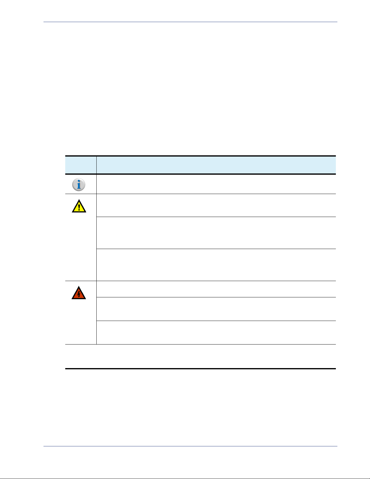
DocumentConventions
Tab l e 1 provides an easy way to recognize information of particular importance in this manual
Table 1. Document Conventions
When
you see: It means:
Notes point out information that may not be part of the text but provide tips and other helpful
advice.
Cautions let you know that an action may have undesirable consequences if the instructions are
not followed correctly. Cautions also indicate that failure to follow guidelines could cause damage
to equipment or loss of data.
Les symboles "ATTENTION", représentés par l'icône de gauche, indiquent qu'une action peut
avoir des conséquences indésirables si les instructions ne sont pas suivies correctement.
Les symboles " ATTENTION " indiquent également que le fait de ne pas suivre les instructions
peut causer des dommages à l'équipement ou résulter en une perte de données.
Das links abgebildete Symbol
Konsequenzen haben kann, falls die Anweisungen nicht korrekt befolgt werden.
Das Symbol Vorsicht weist außerdem darauf hin, dass Geräte beschädigt oder Daten verloren
gehen können, wenn die Anweisungen nicht befolgt werden.
Vors i cht weist darauf hin, dass ein Vorgang unerwünschte
Warnings indicate that failure to take the necessary precautions or to follow guidelines could
cause harm to equipment and personnel.
Les symboles "
de ne pas prendre les précautions nécessaires ou de ne pas suivre les instructions peut
endommager l'équipement ou provoquer des blessures.
Das links abgebildete Symbol
Personen verletzt werden können, wenn die notwendigen Vorsichtsmaßnahmen nicht
eingehalten oder die Anweisungen nicht befolgt werden.
Hyperlinks: Clicking any
Localization: See
caution and warning statements in this manual.
Appendix , “Localized Cautions and Warnings” for the French and German versions of the
AVERTISSEMENT ", représentés par l'icône de gauche, indiquent que le fait
Warnung weist darauf hin, dass Geräte beschädigt oder
blue link takes you to the item to which the link refers.
SelenioTM VMG-14+ Hardware Setup Guide 10
Graphics Gen2 Release 1.4.0
Graphics
In some cases the line art and screen-shots shown in this manual may differ slightly from what appears
on the actual product.
All efforts have been made to ensure that the latest images are used. In all cases, the functionality
described is current at the time of writing.
TechnicalAssistance
Use the contact information provided in this section if you need to phone or write to Imagine
Communications Customer Support for assistance with VMG installation, initial configuration, or other
VMG product issues.
Table 2. Contact Information for Product Returns
To Do This... Use this contact information
Return product.
Request authorization from
Imagine Communications to
return materials
Affix proper address on the
return shipment
Customer Portal:
Phone
From inside USA:
From outside USA:
Email
Company Address
RMA Number
http://support.rgbnetworks.com
1.877.RGB.NETW
(977.742.6389)+1.408.701.2800
support@rgbnetworks.com
Use address and RMA number, as advised by
your Imagine Communications Customer
Support contact.
See also the RBG Networks web site at
http://www.rgbnetworks.com/support for more details.
SelenioTM VMG-14+ Hardware Setup Guide 11

CHAPTER 2
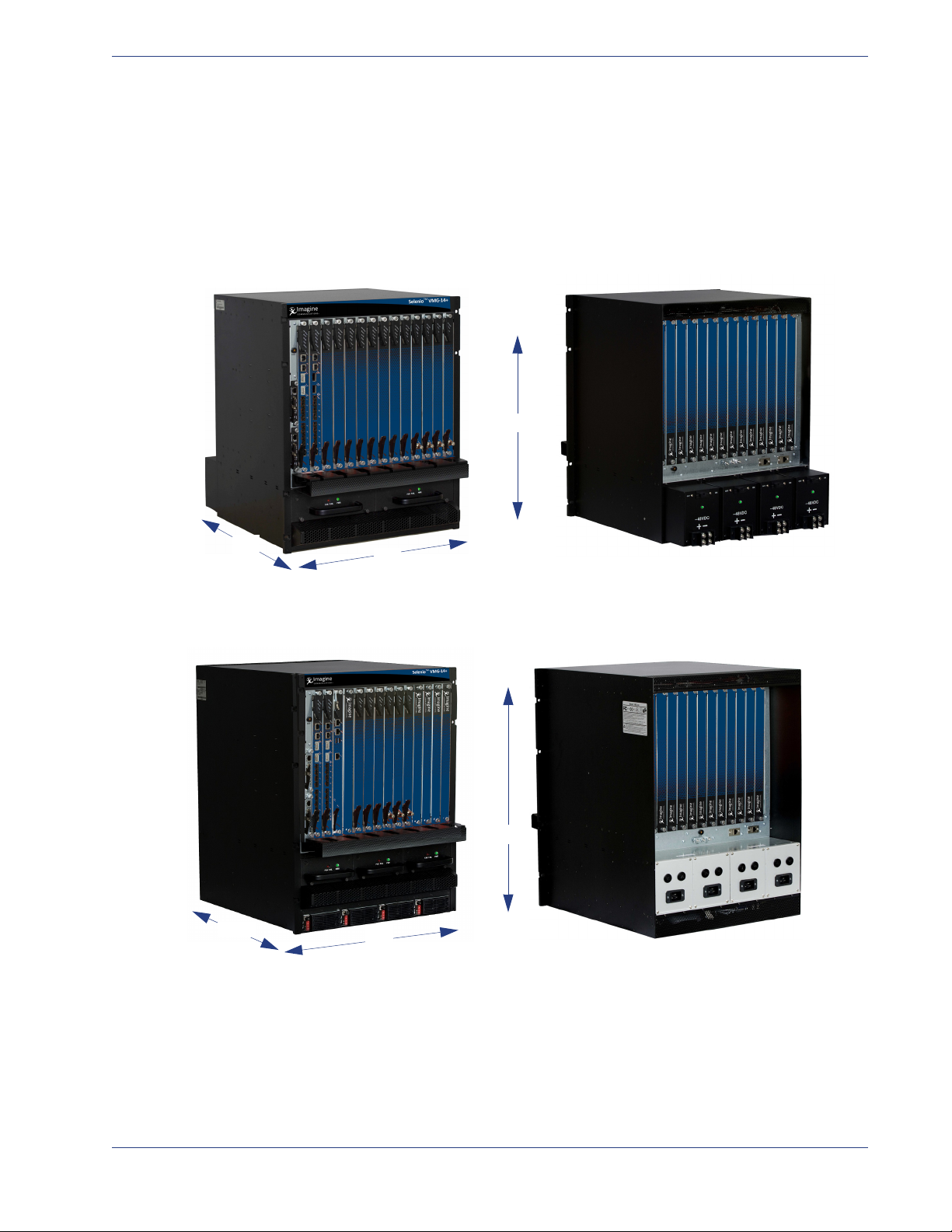
VMG-14+ AC System VMG-14+ DC System
The Imagine Communications Video Multiprocessing Gateway (VMG) products provide stream routing,
switching and video processing for deployment of digital simulcast, digital broadcast and IPTV
streaming in advanced digital cable TV and Telco IPTV networks.
The 14-slot (300-watt) Video Multiprocessing Gateway “Plus” system (VMG-14+) from Imagine
Communications is provides high-level carrier-class service availability through the chassis, servicelevel, and module-level redundancy and is engineered for future-proof operations. It is ideally suited
for operations at lower density video headends and hub sizes, to deliver the industry’s highest density
digital video solution per-rack-unit for grooming, statistical multiplexing, and digital program insertion
(DPI), and transcoding.
The VMG-14+ is fully MPEG-2 and H.264 compliant and interoperable with leading video industry
equipment; it shares the same software functionality and application modules (NPMs, AMPs, TCMs,
and VPMs) as all other VMG systems. This chassis is available either as an AC or DC system (
and all system modules and shelf management modules are conveniently loaded at the front of the
chassis cage.VMG-14+ chassis slots support up to 300 watts each, to enable seamless migration to
future high capacity modules. The VMG-14+ provides advanced standard definition (SD) and high
definition (HD) MPEG-2 and MPEG-4/H.264 video processing, which enables telecommunications
deployment of next-generation cable and IPTV services.
Figure 1. VMG-14+ Chassis
Overview
Figure 1)
SelenioTM VMG-14+ Hardware Setup Guide 12

In This Chapter: Gen2 Release 1.4.0
InThisChapter:
• “Product Features,” next.
• “VMG-14+ Chassis and Components” on page 14.
• “Network Processor Modules” on page 23.
• “VMG-14+ System Modules” on page 26.
• “System Power” on page 30.
• “Cable Management” on page 33.
• “Filler Panels” on page 34.
ProductFeatures
In addition to being software-upgradeable, scalable and reliable, the VMG-14+ platform has the
following features:
• Up to 300 watts per slot.
• Web-based embedded management.
• Front-loading, hot-swappable Video Processor Modules (VPMs), Transcoding Modules (TCM,
TCM2, TCM2+), Network Processor Modules (NPM or NPM2), Application Media Processors
(AMPs), and (two) fan trays.
• Redundancy:
- Intelligent Platform Management Bus (IPMB) interfaces in a radial configuration.
- 1:1 Shelf Control Manager (SCM), 1:1 NPM or NPM2 (and AMP) redundancy, N+M VPM and
TCM redundancy, and service-level redundancy.
- Redundant Power Entry Modules (PEMs).
• Mounting flanges for 19” cabinets.
• Chassis size:
- AC system = 14 RU
- DC system = 13 RU
• 14 front-loading slots: Two dedicated for NPM or NPM2 insertions.
SelenioTM VMG-14+ Hardware Setup Guide 13
VMG-14+ Chassis and Components Gen2 Release 1.4.0
FRONT
13 RU
REAR
19”
21”
FRONT REAR
14 RU
20”
19”
VMG‐14+ChassisandComponents
The VMG-14+ utilizes a chassis platform fitted either for 13 RU (DC system) or 14 RU (AC system). The
front of the VMG-14+ chassis cage accommodates all system and application modules. For AC systems
(
Figure 3), the front also includes the AC PSUs located in the power bay at the base of the system.
Figure 2. VMG-14+ DC System
Figure 3. VMG-14+ AC System
SelenioTM VMG-14+ Hardware Setup Guide 14
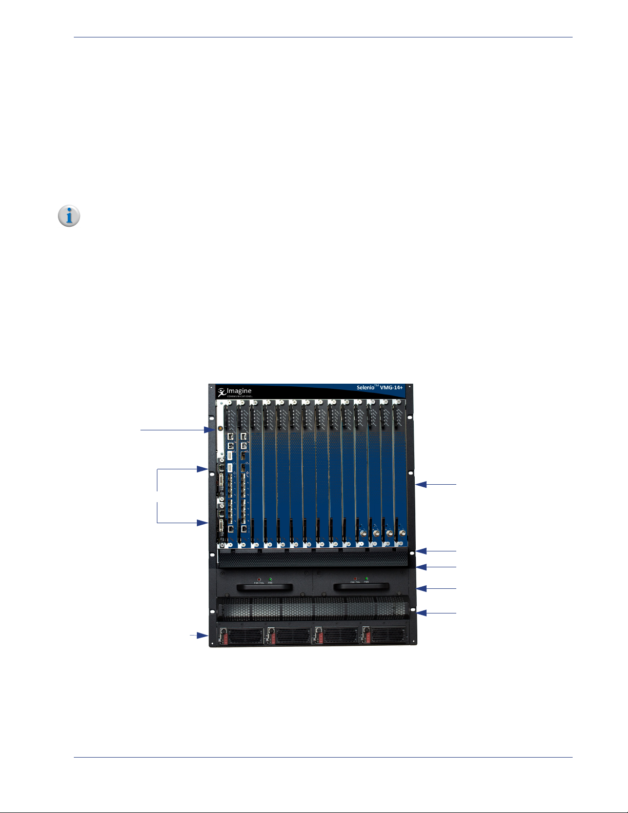
VMG-14+ Chassis and Components Gen2 Release 1.4.0
Power Bay: AC PSUs
Air Intake Grid
Fan Trays
Fan Filter Tray
Cable Management
Bracket
Card Cage:
Slots 1 through 14
ESD Jack
Shelf Control Modules
SCM 2
SCM 1
PSU 4 PSU 3 PSU 2 PSU 1
ChassisFront
The VMG-14+ chassis cage front provides 14 vertical slots for loading of the application modules. Two
of these slots are dedicated for use by Network Processor Modules (NPM or NPM2) for 1:1 redundancy
configuration.
• If the VMG-14+ is using GEN2 NPM2 cards, the remaining 12 slots can be used for Transcoding
Modules (TCM2, or TCM2+).
• If the VMG-14+ is using GEN1 NPM cards, the remaining 12 slots can be used for Video Processor
Modules (VPM), Transcoding Modules (TCM), and up to two Application Media Processors (AMPs).
Note: Rules for loading the various modules are applicable. See “Basic Chassis Populations” on page 18
for more information.
System modules fit into numbered slots, from left (1) to right (14). Up to two Shelf Manager modules
fit into the two vertical slots at the left edge of the chassis, alongside slot 1. The AC (
(
Figure 5) VMG chassis are identical except for the inclusion of AC PSUs at the base of the AC chassis.
Figure 4) and DC
For slot assignments, see
Tab l e 3 .
Rack-mounting flanges are incorporated into the chassis at the left and right front edges, to enable
front-mount at the rack. During installation, you will prepare the rack by attaching a chassis shelf to it,
which will support the rear of the rack-mounted chassis.
Figure 4. VMG-14+ Front—AC System
SelenioTM VMG-14+ Hardware Setup Guide 15
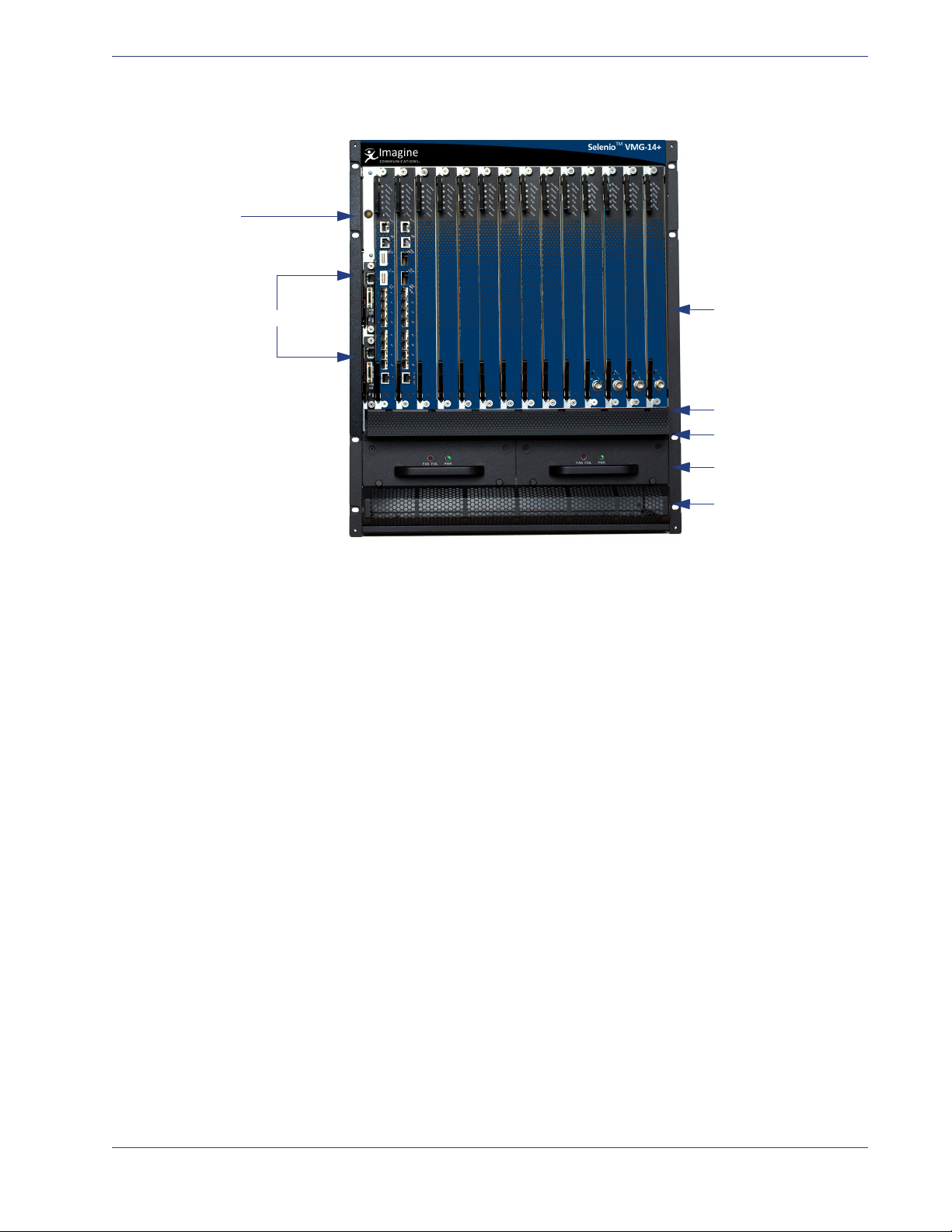
VMG-14+ Chassis and Components Gen2 Release 1.4.0
Air Intake Grid
Fan Trays
Fan Filter Tray
Cable Management
Bracket
Card Cage:
Slots 1 through 14
ESD Jack
Shelf Control Modules
SCM 2
SCM 1
Figure 5. VMG-14+ Front—DC System
SelenioTM VMG-14+ Hardware Setup Guide 16

VMG-14+ Chassis and Components Gen2 Release 1.4.0
Card Cage:
Slots 1 through 14
for RTMs
ESD Jack
Air Intake Grid
Power Bay:
AC PEMs
Chassis GND
Card Cage:
Slots 1 through 14
for RTMs
ESD Jack
Power Bay:
DC PEMs
Chassis GND
ChassisRear
The rear chassis cage contains the power entry modules at the base of the system. All slots at the rear
card cage are covered with RTMs. These must not be removed.
Figure 6. VMG-14+ Rear —AC System
Figure 7. VMG-14+ Rear —DC System
SelenioTM VMG-14+ Hardware Setup Guide 17

VMG-14+ Chassis and Components Gen2 Release 1.4.0
BasicChassisPopulations
Slot assignments determine where to load the system modules, SCMs, fan trays, air filter, and (for AC)
power supply units. The VMG-14+ supports the components and modules listed in
:
Table 3. VMG-14+ Chassis Modules and Components
Name Description
Network Control
Processor (NPM and
NPM2)
System modules Family of modules that includes AMP, TCM,
Shelf Control
Manager (SCM)
DC Power Entry
Modules (PEMs)
DC PEM Terminal
Block Cover(s)
AC Power Entry
Modules
AC Power Supplies 4 Front:, in power bay
Either NPM type provides management
functions and ingress/egress for transport
streams.
The NPM2 also provides packet inspection.
Compatibility Notes:
• The NPM is compatible with the TCM
card.
• The NPM2 is compatible with TCM2 or
TCM2+ cards.
• Various models of NPM cards cannot be
mixed. Use only NPM or only NPM2 cards
in your VMG-14+.
See also
page 23
TCM2, TCM2+, and VPM.
Compatibility Notes:
• The TCM, AMP, and VPM is compatible
• The TCM2 or TCM2+ is compatible with
• Various models of TCM cards cannot be
See also
page 26
Manage power and cooling, and system
inter-connectivity via interaction between
the SCM and Intelligent Management
Controllers (IPMC) over IPMB-0.
Enable system management through
Ethernet.
See also
page 19
See also
See also
“Network Processor Modules” on
.
with NPM.
NPM2 only.
mixed.Use only TCM, TCM2, or TCM2+ in
your VMG-14+.
“VMG-14+ System Modules” on
.
“Shelf Control Managers” on
.
“DC System Power” on page 32. 4 Rear: in power bay
“AC System Power” on page 30. 4 Rear: in power bay
System
Capacity
•NPM: 2
or
•NPM2: 2
•AMP: 2
• Others: up
to 12
2 Front, vertically
4 For attachment to
Tab l e 3.
Slot Assignments
Front,
slots 1 and 2.
Front,
slots 3 through 14.
stacked slots at left
of Slot 1.
SCM2 (top)
SCM1 (bottom)
of DC systems.
DC PEM(s)
of AC systems.
of AC systems.
SelenioTM VMG-14+ Hardware Setup Guide 18

VMG-14+ Chassis and Components Gen2 Release 1.4.0
Ethernet Link
Activity Status
RJ-45 Port ResetRS-232 Port
(not used)
Hot Swap
LED
SCM Status LED
Alarm
Cutoff
Fault
LEDs
Extraction
Lever
Fixing
Screw
Fixing
Screw
Table 3. VMG-14+ Chassis Modules and Components (Continued)
Name Description
Filler Panels
• Front Filler
• RTM Filler Panels
Fan Tray See also
Fan Filter Tray See also
See also
“Filler Panels” on page 34. all empty slots
“Fan Trays” on page 21. 2 Fan Tray slot, below
“Fan Filter Tray” on page 22. 1 Front of chassis,
System
Capacity
Slot Assignments
cable management
tray.
above fan trays, and
below cable
management tray.
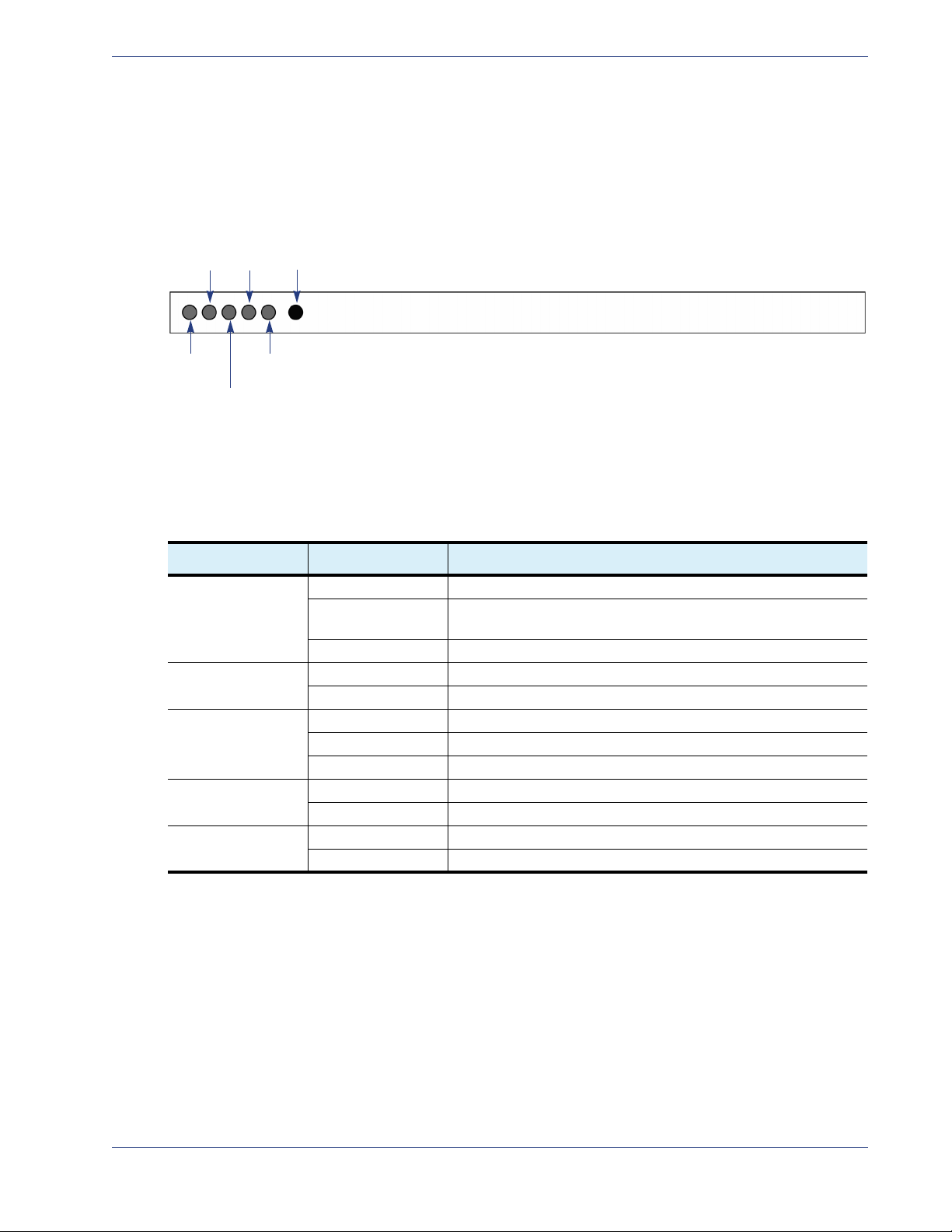
ShelfControlManagers
The VMG-14+ SCMs fit into the dedicated SCM slots located at the left-front-edge of the chassis. Two
SCMs are required for redundancy, and an SCM in either slot can serve as the primary. When the active
is removed, the remaining SCM changes state—from standby to active.
Note: Although each Shelf Manager module contains a mini DB25 Telco Alarm interface at the RS-232
port, telco alarm LEds, and Telco alarm cutoff push button, the current release does not support
Telco alarm functionality.
The SCM faceplate provides the LEDs and components illustrated in
Figure 8. Shelf Control Manager Front Panel
Table 4. Shelf Control Manager—Front Panel
LED Name Color/Condition Description
Cutoff Button n/a Not supported for the current release.
Reset Button (RST) n/a Reset (power cycle) the SCM. Use a small pointed
Fault LEDs Green Temperature normal: not exceeding thresholds. This
Red Temperature exceeds thresholds.
object to access and depress this button.
LED illuminates upon system power-up.
Figure 8, and described in Ta b le 4 .
SelenioTM VMG-14+ Hardware Setup Guide 19

VMG-14+ Chassis and Components Gen2 Release 1.4.0
Table 4. Shelf Control Manager—Front Panel (Continued)
LED Name Color/Condition Description
SCM Status (ShMM) Solid Green Active. This LED illuminates upon system powerup.
Blinking Green Standby.
Red Failure.
Hot Swap (FRU) Off SCM is not ready to be removed or disconnected from
the chassis.
Blue SCM is ready to be removed or disconnected from the
chassis.
RJ-45 port Solid/blinking green
Note that the RJ45 LEDs
illuminate even if the cable is
not inserted, to report status
of Ethernet link activity over
the VMG-14+ backplane.
RS-232 port n/a Not supported in the current release for Telco alarm
10/100 link status and activity.
10: The RJ-45 port is operating in 10 Mbps mode
(data is being received or transmitted at 10 Mbps).
100: The RJ-45 port is operating in 100 Mbps mode
(data is being received or transmitted at 100 Mbps).
Pinouts for this port are provided in
Connector,” on this page.
functions. However, you can directly connect to it for
troubleshooting purposes. See also
Configuration—SCM” on page 20, and “10/100
Ethernet Connector” on page 21
“10/100 Ethernet
“Serial Console
.
Steps for servicing of the Shelf Control Managerare provided in Chapter 5, Shelf Control Manager
Servicing
on Page 64.
SerialConsoleConfiguration—SCM
• 115200 baud
• No parity
• 8 data bits
• 1 stop bit
• no flow control
SelenioTM VMG-14+ Hardware Setup Guide 20
VMG-14+ Chassis and Components Gen2 Release 1.4.0
Fan Tray
FRONT
Fan Tray 1 Fan Tray 2
10/100EthernetConnector
Pinouts for the SCM RJ-45 port are provided in Tabl e 5.
Table 5. RJ-45 Port Pinouts—VMG-14+ SCM
Pin Description
1TX+
2TX3RX+
4, 5 Unused pair
6RX7, 8 Unused pair
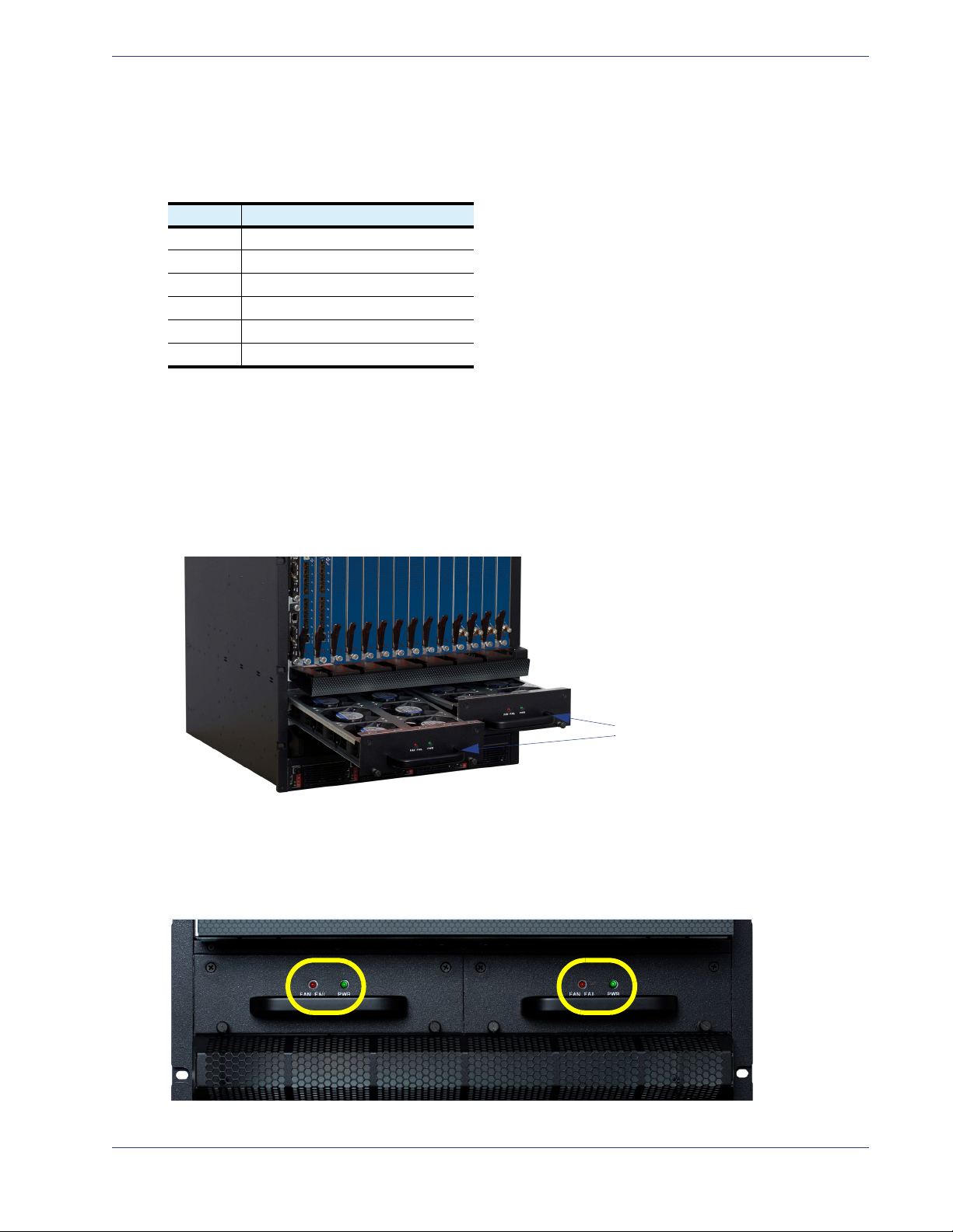
FanTrays
The fan trays operate continuously to provide cooling to the system and are monitored by the SCM. In
the event of a failure—such as a fan problem or removal of both SCMs—the remaining fans continue
to run at full speed. The fan trays are hot swappable field-replaceable units. The VMG-14+ chassis
contains two fan trays, which fit into the base of the chassis at the front. Each fan tray contains six fans
(
Figure 9).
Figure 9. Fan Trays and Fans
FanTrayLEDs
Fan Tray LEDs are located on the Fan Tray front panel (Figure 10) and are described in Table 6 .
Figure 10. Fan Tray LEDs
SelenioTM VMG-14+ Hardware Setup Guide 21
VMG-14+ Chassis and Components Gen2 Release 1.4.0
Fan Filter Tray Handles
Grid:
Top of Fan Filter Tray
Table 6. Fan Tray LEDs
Color Description Status Condition
Red Alarm LED Solid
Red
Green Normal
operation
Solid
green
Indicates a failure condition. Also, this LED is lit upon system powerup. Thereafter the LED is either OFF or ON.
•OFF
Fan speed is normal and does not exceed normal threshold.
•ON
Fan speed is exceeding the normal speed, due to critical alarm.
• Following system initialization: indicates success.
• During operations: indicates that no problems are detected with
the fans, fan tray, or system temperature.
The fan tray replacement procedure is provided in Chapter 5, Fan Tray Removal on Page 64.
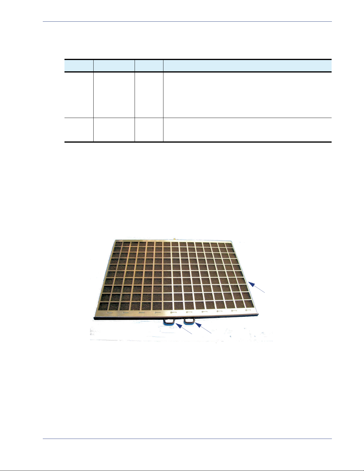
FanFilterTray
The VMG-14+ chassis uses a front replaceable Fan Filter Tray (Figure 11). During operations, the system
detects the presence of the fan filter, and the fan filter must be in place at all times. The tray inserts
horizontally into the chassis front, at the fan filter slot directly above the Fan Trays.
This unit has a grid surface on one side, and a foam liner on the opposite side. The grid (shown below)
must be uppermost when installing the Fan Tray Filter at the VMG-14+.
Figure 11. VMG-14+ Fan Filter
Fan filter maintenance and replacement information is provided in “Fan Tray Servicing” on page 64.
SelenioTM VMG-14+ Hardware Setup Guide 22
Network Processor Modules Gen2 Release 1.4.0
Hot
Swap
Config
Backup
Status Fault Reset
RJ-11
Serial
Port
Not used
10 GigE
XFP1
XFP2
1 GigE
SFP 1-4 SFP 5-8
10/100
baseT
Hot
Swap
Config
Backup
Status Fault
Reset
RJ-11
Serial Port
Not used
10/100
(Management
1 GigE /10 GigE (Data)
SFP 1-4 SFP 5-8
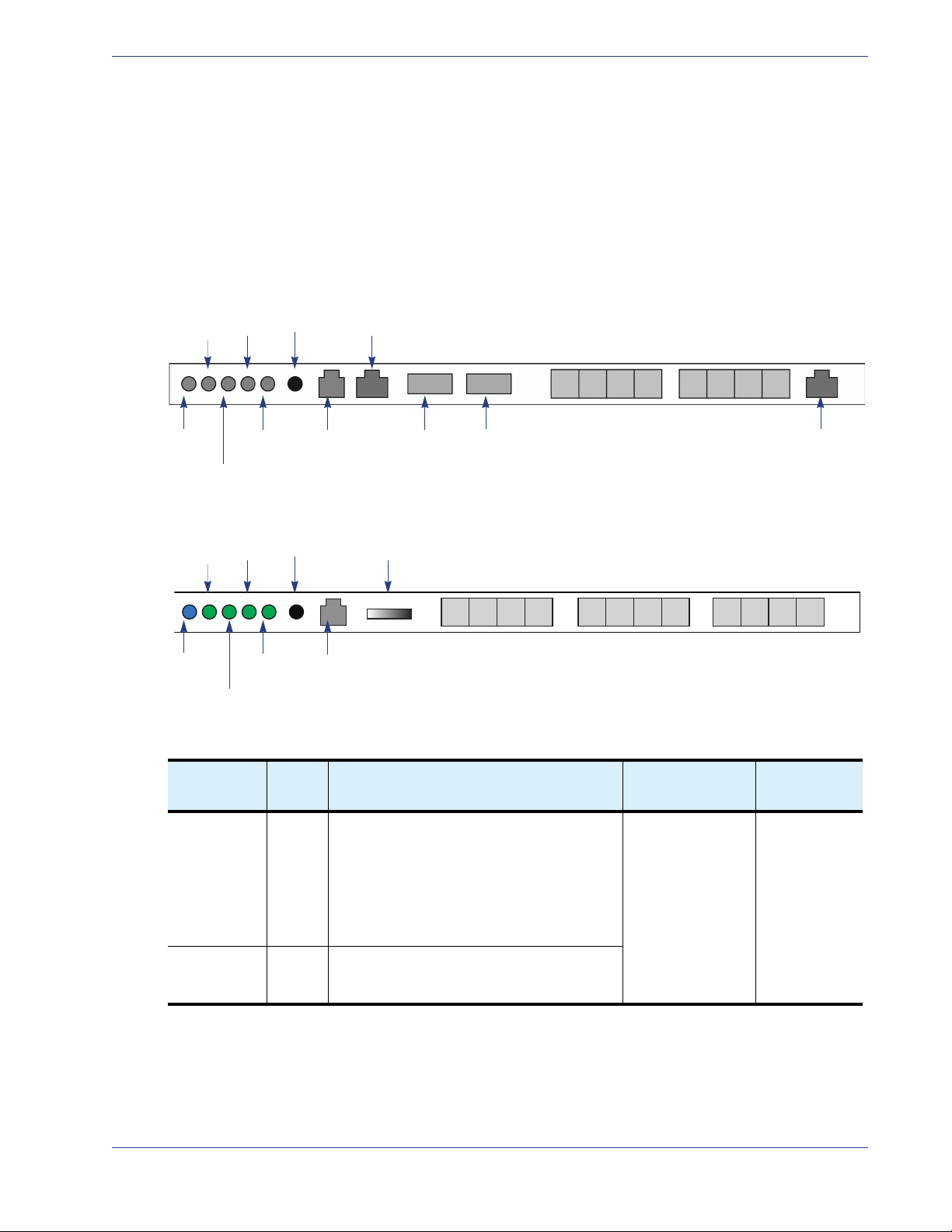
NetworkProcessorModules
The Network Processor Modules are the NPM and NPM2 cards. These modules share common physical
characteristics (
in the following sections:
• “NPM and NPM2 Interfaces” on page 24.
• “NPM and NPM2 LEDs” on page 24.
• “NPM and NPM2 Management and Serial Ports” on page 25.
Figure 12. NPM Front Panel
Figure 12 and Tab l e 7 ) which provide the interfaces, indicators and functions described
Figure 13. NPM2 Front Panel
Table 7. NPM Models
Name
Network
Processor
Module
Network
Processor
Module2
Front
Panel
Label
NPM Purpose: receive and transmit MPEG-2 and
NPM2 Identical to the NPM, plus packet inspection
Description System Capacity
H.264 transport streams carried in an SPTS
and/or MPTS, encapsulated with UDP / IP or
RTP / UDP / IP over GigE or 10GigE in
GEN1 VMG:
• System management functions.
• Supports 1:1 module redundancy.
for GEN2 VMG.
• Up to two.
• At least one is
required.
Slot
Assignments
1, 2
SelenioTM VMG-14+ Hardware Setup Guide 23

Network Processor Modules Gen2 Release 1.4.0
NPMandNPM2Interfaces
ManagementInterfaces
• Eight bi-directional GigE ports:
- Each GigE port supports small form factor pluggable (SFP) (16mm H x 42mm D) optical
modules with a data rate of 1.0625Gbps according to IEEE-802.3z.
- Each GigE port supports either single mode or multimode SFP optical modules (the NPM
supports both types simultaneously), and operates on frequencies compliant with the optical
channel plan defined in ITU G.692, 100 GHz channel plan appendix IV.
- The NPM supports SFP modules with wavelengths of SX 850nm for short distances up to
65 meters, LX 1310nm for medium distances up to 10 kilometers, or LX 1550nm for long
distances up to 70 kilometers.
- The GigE port also supports SFP copper modules of full duplex 1000BaseT Ethernet with
copper interfaces that are compliant with IEEE-802.3ab. The copper SFP module supports
distances up to 100 meters.
DataInterfaces
• NPM: Two 10GigE ports
NPM2: Four 10GigE ports
- Each 10GigE port supports pluggable 10 Gigabit small form factor pluggable (XFP) (23.5mm H
x 67mm D) optical modules that are IEEE-802.3ae compliant with data rates of 10.3125Gbps.
The NPM supports XFP modules with wavelengths of 850nm for distances from 26 meters to
300 meters, depending on the grade of fiber, and 1310nm for distances up to 10 kilometers.
- Each 10GigE port receives input as MPEG-2 SPTS and MPTS with unicast or multicast, de-jitters
up to 100ms of network jittering and routes the video or data streams to the appropriate
application module (VPM, TCM, AMP).
- The 10GigE ports can handle either constant bit rate (CBR) or variable bit rate (VBR) MPEG-2 as
well as H.264 digital video streams in both SD and HD format, then deliver the processed video
content over MPEG-2TS / UDP / IP / GigE or MPEG-2TS / RTP / UDP / IP / GigE unicast or
multicast IP transport.
• NPM only: One Fast Ethernet (10/100BaseT) Management port for management and control,
including SCTE 30 messages.
• One RJ-11 serial console interface for management access and event logging.
• Reset button.
NPMandNPM2LEDs
The NPM and NPM2 faceplate provides the LEDs listed in Tabl e 8.
Table 8. NPM Front Panel LED Description
LED Name Color/Condition Description
Hot Swap Blue NPM is ready for hot-swap.
Flashing Blue Transition between the hot-swap not-ready state to ready state, or
from ready state to hot-swap not-ready state.
Off NPM is not ready for hot-swap.
SelenioTM VMG-14+ Hardware Setup Guide 24
Network Processor Modules Gen2 Release 1.4.0
Table 8. NPM Front Panel LED Description (Continued)
LED Name Color/Condition Description
Status Red Chassis interface is in fault state.
Green NPM payload powered and out of reset.
Config Red FPGA configuration in progress.
Green FPGA configuration is done.
Fault Red Fault.
Green In normal operation.
Backup Red Standby.
Green In operation.
Note: For a list of SFP and XFP modules approved for use with the NPM or NPM2, please refer to the
VMG release notes and/or Imagine Communications Customer Portal.
NPMandNPM2ManagementandSerialPorts
The NPM and NPM2 provides one 10/100BaseT Ethernet interface with an RJ-45 connector, compliant
with IEEE-802.3ab. A serial console port with an RJ-11 connector is also provided.
SerialConsoleConfiguration—NPMandNPM2
• 19200 baud
• No parity
• 8 data bits
• 1 stop bit
• no flow control
SerialPortPinouts—NPMandNPM2
Table 9. NPM Serial Reference
Pin
Number
1 No Connect
2TXD
3RXD
4 No Connect
5GND
6 No Connect
Name
SelenioTM VMG-14+ Hardware Setup Guide 25
VMG-14+ System Modules Gen2 Release 1.4.0
VMG‐14+SystemModules
The VMG-14+ platform supports the service module suite listed in Ta b le 1 0 . These modules are
inserted into the front of the chassis cage for connection to the chassis backplane. During operations,
the installed modules provide high speed routing and inter-module communication paths.
Note: All VMG-14+ modules are hot swappable.System indicators are provided to ensure safe card
swaps (see also
.
Table 10. VMG-14+ System Modules
Name
Application
Media Processor
Video Processor
Module
Transcoding
Module
“Hot Swap Indicators” on page 60).
Front
Panel
Label
AMP Purpose: Audio transcoding for GEN1 VMG.
VPM Purpose: Video and data traffic, and control
TCM,
TCM2,
TCM2+
Description
• Pairs with an NPM by connecting its
Ethernet ports to ports 7 and 8 on the
NPM.
• See also
on page 29.
messages for GEN1 VMG:
• Statistical multiplexing for SD programs
and HD programs, and concurrent
transrating.
• Digital ad insertion for CBR or VBR H.264
video and MPEG-2 video program
streams.
• See also
page 27.
Purpose: Video transcoding.
• NPM or NPM2 interfacing through the
Selenio VMG chassis backplane, via the
high speed bus fabric for the video and
data traffic, and control messages.
• Transcoding functions: MPEG-2 to H.264
SPTS, H.264 to MPEG-2 SPTS, or
MPEG-2 to MPEG-2 SPTS.
• Video resolution handling, up to HD
resolutions.
• High capacity support for multiple HD
streams through single device:
• TCM and TCM2: up to 12 HD
• TCM2+: up to 24 HD streams.
• See also
page 28
“Application Media Processor”
“Video Processor Module” on
streams.
“Transcoding Modules” on
.
System
Capacity
Up to two 3 (to pair with
Up to 12 Slots 3 to 14
Up to 12 Slots 3 to 14
Slot
Assignments
NPM slot 1)
4 (to pair with
NPM in slot 2)
SelenioTM VMG-14+ Hardware Setup Guide 26
VMG-14+ System Modules Gen2 Release 1.4.0
Hot
Swap
Config
Backup
Statu
Fault
Reset
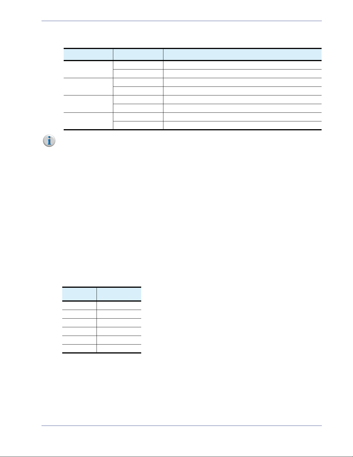
VideoProcessorModule
The VPM (Figure 14) provides the indicators described in the following section:
• “VPM LEDs” on page 27.
Figure 14. VPM Front Panel
VPMLEDs
The VMP faceplate provides the LEDs list in Tabl e 11 .
Table 11. VPM Front Panel LEDs
LED Name Color/Condition Description
Hot Swap Blue VPM is ready for hot-swap.
Flashing Blue VPM is making transition from hot-swap not ready to ready state,
or from ready state to hot-swap not-ready state.
Off VPM is not ready for hot-swap.
Status Red Chassis interface fault.
Green Payload up.
Config Red FPGA configuration in progress.
Green FPGA configuration completed.
Orange FPGA failure: reverting to factory defaults.
Fault Red Fault.
Green Normal operation.
Backup Red Standby.
Green In operation.
SelenioTM VMG-14+ Hardware Setup Guide 27

VMG-14+ System Modules Gen2 Release 1.4.0
SDI Monitoring Port
LED
Hot
Swap
Config
Backup
Status
Fault Reset
Reset
SDI Monitoring Port
(not currently in
use)
TranscodingModules
The family of transcoding modules includes the TCM, TCM2, and TCM2+, which share common
characteristics at their faceplates (
“TCM, TCM2, TCM2+ LEDs,” on this page.
Figure 15. TCM, TCM2, TCM2+ Front Panel
For TCM usage in the VMG-14+, the TCM must be compatible with the installed NPM or NPM2:
Figure 15) and provides the indicators and functions described in
• Use TCM only with NPM (GEN1 VMG).
• Use TCM2 or TCM2+ only with NPM2 (GEN2 VMG).
TCM,TCM2,TCM2+LEDs
The TCM, TCM2, TCM2+ faceplate provides the LEDs listed in Ta b le 1 2.
Table 12. TCM, TCM2, TCM2+ Front Panel LEDs
LED Name Color/Condition Description
Hot Swap Blue TCM is ready for hot-swap.
Flashing Blue TCM is making transition from hot-swap not-ready to ready state,
or from ready state to hot-swap not-ready state.
Off TCM is not ready for hot-swap.
Status Red Chassis interface fault.
Green Payload up.
Config Red FPGA configuration in progress.
Green FPGA configuration completed.
Fault Red Fault.
Green Normal operation.
Backup Red Standby.
Green In operation.
SDI Monitoring Port
LED
n/a This LED is currently not used.
SelenioTM VMG-14+ Hardware Setup Guide 28
 Loading...