

Imagine communications Selenio BNP 2xr, Selenio BNP 3xr User Manual

User Guide
TM
Selenio
Broadcast Network
Processor (BNP)
Release 3.7.1
18-December-2015
Revision A

SelenioTM BNP User Guide, Release 3.7.1
Document part number: 250-0363-01 Rev. A
Printed 12/18/15
Publication Information
Copyright 2005-2015 Imagine Communications Corp. Proprietary and Confidential.
This material is protected by the copyright laws of the United States and other countries. No part of this document may be
reproduced, distributed, or altered in any form, by any means, by any entity nor may it be used to make any derivative work
(such as translation, transformation, or adaptation) except in accordance with applicable agreements, contracts, or
licensing, without the express written consent of Imagine Communications. All other uses are illegal.
Notice
This publication is designed to assist in the use of the product as it exists on the date of publication of this manual, and may
not reflect the product at the current time or an unknown time in the future. This publication does not in any way warrant
description accuracy or guarantee the use for the product to which it refers. Imagine Communications reserves the right,
without notice to make such changes in equipment, design, specifications, components, or documentation as progress may
warrant to improve the performance of the product.
Trademarks
SelenioTM and TelurioTM are trademarks of Imagine Communications. Microsoft® and Windows® are registered
trademarks of Microsoft Corporation. All other trademarks and trade names are the property of their respective companies.
Patents
The products described herein are covered by one or more U.S. and foreign patents pending.
U.S. Patents: 6,996,129; 7,046,677; 7,818,355; 8,180,920. Other US and foreign patents pending.
Contact Information
Imagine Communications has office locations around the world. For domestic and international location and contact
information see: http://www.imaginecommunications.com/contact-us/
Support Contact Information
For domestic and international support of Selenio VMG, Selenio BNP, Selenio SEP, Selenio MMC, Selenio TAT, Telurio
Packager, Telurio Recording Manager, and Telurio BNP products, contact:
Support Contacts: support@rgbnetworks.com
For domestic and international support of all other Imagine Communications' products not mentioned above, contact:
Support Contacts: http://www.imaginecommunications.com/services/technical-support/
http://app.imaginecommunications.com/customercommunity
1.866.4.Imagine // (1.866.446.2446) - Inside North America
+1.44.208.339.1900 - Europe & Africa
+971.4.433.8260 - Middle East
+852.2776.0628 - Asia
Selenio BNP User Guide, Release 3.7.1 2

Document Change History
BNP Element Manager User Guide document history
Part Number Software Version Release Date Document Changes
250-0363-01 rev. A 3.7.1 12/18/15 •Program redundancy.
•RTP support.
•AAA: support for custom user privileges.
•Option to force reallocation of output TSs .
•Shutdown now includes video shutdown.
•Ghost program data PID can be groomed with ES.
250-0309-01 rev A 3.7.0 11/2 0/14 •New 2xr+ presentation at Element Manager GUI
•Support for E-AC-3 audio.transcoding.
250-0188-01 rev A 3.5.4 1/28/13 Support for selection of both short and long names for
ATS C ou tpu t pr ogra ms.
250-0164-01 rev A 3.5.2 8/7/12 Update to remove crawl speed restrictions.
250-0160-01 rev A 3.5.1 6/21/12 Minor changes:
•Descriptions: global postBlack, and change MPEG2 advanced rate control to MPEG-2 aggressive rate
control.
•Add long delay for H.264 DPI to output TS.
250-0146-01 rev A 3.5.0 4/30/12 •Quick Keys/shortcuts.
•Updated safety information.
•Updates for localization
250-0136-01 rev A 3.4.0 12/18/15 •Support for 1800 EAS characters (EAS CAP)
•Audio splice with type mismatch
•Support for DSCP
•PSMON improvement
250-0125-01 rev A 3.3.2 9/6/11 •Maintenance release.
250-0106-01 rev A 3.3.0 6/24/11 •Changed part number
•Support for up to 512 user-created input TSs
•Support for up to 1527 dynamically created input
TSs
•Support for up to 4 source IP addresses per
multicast input TS
•Support for PCR Interval for Stripped NULL Packet
•Support for DPI Splicing
250-0098-01 rev A 3.2.1 05/16/2011 •Changed part number
•Network cue forwarding during DPI
•PSI & PSIP pass-through
•H.264 enhancements for HD
250-0052-01 rev E 3.2.0 03/02/2011 •DPI cue and postblack handling
250-0052-01 rev D 3.1.1 02/23/2011 •Added appendix of Caution and Warning
statements in French and German and TÜV GS
certification
Selenio BNP User Guide, Release 3.7.1 3

BNP Element Manager User Guide document history
Part Number Software Version Release Date Document Changes
250-0052-01 rev C 3.1.1 10/18/2010 •Added transparency support for Non-Ascii text.
•Added EBIF support.
•Added AAA User Authentication.
•DC power supply support.
•Enhanced NTP synchronization feature.
•Output TS modification enhancements.
•DVB-CA enhancements.
•Added ES-level grooming.
250-0052-01 rev B 3.0.1 05/07/2010 •Added Operator, Advanced Messaging, and Logo
Overlay scheduling feature.
•PSIP enhanced grooming configuration.
250-0052-01 rev A 3.0 02/18/2010 Production Release
Selenio BNP User Guide, Release 3.7.1 4

Table of Contents
Publication Information . . . . . . . . . . . . . . . . . . . . . . . . . . . . . . . . . . . . . . . . . . . . . . . . . . . . . . 2
Notice . . . . . . . . . . . . . . . . . . . . . . . . . . . . . . . . . . . . . . . . . . . . . . . . . . . . . . . . . . . . . . . . . . . 2
Trademarks. . . . . . . . . . . . . . . . . . . . . . . . . . . . . . . . . . . . . . . . . . . . . . . . . . . . . . . . . . . . . . . 2
Patents. . . . . . . . . . . . . . . . . . . . . . . . . . . . . . . . . . . . . . . . . . . . . . . . . . . . . . . . . . . . . . . . . . . 2
Contact Information . . . . . . . . . . . . . . . . . . . . . . . . . . . . . . . . . . . . . . . . . . . . . . . . . . . . . . . . . 2
Support Contact Information . . . . . . . . . . . . . . . . . . . . . . . . . . . . . . . . . . . . . . . . . . . . . . . . . . 2
Document Change History. . . . . . . . . . . . . . . . . . . . . . . . . . . . . . . . . . . . . . . . . . . . . . . . . . . . 3
Chapter 1: Introduction . . . . . . . . . . . . . . . . . . . . . . . . . . . . . . . . . . . . . . . . . . . . . . . . . . . . . . . . . . . . . . . . . 10
Document Organization . . . . . . . . . . . . . . . . . . . . . . . . . . . . . . . . . . . . . . . . . . . . . . . . . . . . . 11
Document Audience. . . . . . . . . . . . . . . . . . . . . . . . . . . . . . . . . . . . . . . . . . . . . . . . . . . . . . . . 11
Related Documentation . . . . . . . . . . . . . . . . . . . . . . . . . . . . . . . . . . . . . . . . . . . . . . . . . . . . . 11
Document Conventions . . . . . . . . . . . . . . . . . . . . . . . . . . . . . . . . . . . . . . . . . . . . . . . . . . . . . 12
Graphics Used . . . . . . . . . . . . . . . . . . . . . . . . . . . . . . . . . . . . . . . . . . . . . . . . . . . . . . . . . . . . 12
Chapter 2: Overview . . . . . . . . . . . . . . . . . . . . . . . . . . . . . . . . . . . . . . . . . . . . . . . . . . . . . . . . . . . . . . . . . . . 13
In This Chapter: . . . . . . . . . . . . . . . . . . . . . . . . . . . . . . . . . . . . . . . . . . . . . . . . . . . . . . . . . . . 13
Product Overview. . . . . . . . . . . . . . . . . . . . . . . . . . . . . . . . . . . . . . . . . . . . . . . . . . . . . . . . . . 13
Product Features . . . . . . . . . . . . . . . . . . . . . . . . . . . . . . . . . . . . . . . . . . . . . . . . . . . . . . . . . . 14
BNP Applications . . . . . . . . . . . . . . . . . . . . . . . . . . . . . . . . . . . . . . . . . . . . . . . . . . . . . . . . . . 15
Grooming, Transrating and Multiplexing . . . . . . . . . . . . . . . . . . . . . . . . . . . . . . . . . . . . . 15
DPI-Based Ad Splicing . . . . . . . . . . . . . . . . . . . . . . . . . . . . . . . . . . . . . . . . . . . . . . . . . . 15
Messaging System Applications . . . . . . . . . . . . . . . . . . . . . . . . . . . . . . . . . . . . . . . . . . . 16
DVB Conditional Access (DVB-CA) Encryption. . . . . . . . . . . . . . . . . . . . . . . . . . . . . . . . 17
BNP Deployment Architecture . . . . . . . . . . . . . . . . . . . . . . . . . . . . . . . . . . . . . . . . . . . . . . . . 17
Redundancy. . . . . . . . . . . . . . . . . . . . . . . . . . . . . . . . . . . . . . . . . . . . . . . . . . . . . . . . . . . . . . 20
Source Specific Muliticast (SSM) Redundancy . . . . . . . . . . . . . . . . . . . . . . . . . . . . . . . . 20
Program Redundancy . . . . . . . . . . . . . . . . . . . . . . . . . . . . . . . . . . . . . . . . . . . . . . . . . . . 20
Port Redundancy. . . . . . . . . . . . . . . . . . . . . . . . . . . . . . . . . . . . . . . . . . . . . . . . . . . . . . . 21
1:1 Chassis-level Redundancy . . . . . . . . . . . . . . . . . . . . . . . . . . . . . . . . . . . . . . . . . . . . 21
Chapter 3: BNP Element Manager Basics . . . . . . . . . . . . . . . . . . . . . . . . . . . . . . . . . . . . . . . . . . . . . . . . . . 23
In This Chapter: . . . . . . . . . . . . . . . . . . . . . . . . . . . . . . . . . . . . . . . . . . . . . . . . . . . . . . . . . . . 23
BNP Element Manager Overview . . . . . . . . . . . . . . . . . . . . . . . . . . . . . . . . . . . . . . . . . . . . . 23
Obtaining Java Runtime Environment . . . . . . . . . . . . . . . . . . . . . . . . . . . . . . . . . . . . . . . . . . 24
Broadcast Network Processor Home Page . . . . . . . . . . . . . . . . . . . . . . . . . . . . . . . . . . . . . . 24
Log in and Access the BNP Element Manager . . . . . . . . . . . . . . . . . . . . . . . . . . . . . . . . 25
Logging Off . . . . . . . . . . . . . . . . . . . . . . . . . . . . . . . . . . . . . . . . . . . . . . . . . . . . . . . . . . . 26
BNP Element Manager GUI. . . . . . . . . . . . . . . . . . . . . . . . . . . . . . . . . . . . . . . . . . . . . . . . . . 26
BNP Element Manager Window . . . . . . . . . . . . . . . . . . . . . . . . . . . . . . . . . . . . . . . . . . . 27
BNP Element Manager Menus . . . . . . . . . . . . . . . . . . . . . . . . . . . . . . . . . . . . . . . . . . . . 28
BNP Element Manager Tabs . . . . . . . . . . . . . . . . . . . . . . . . . . . . . . . . . . . . . . . . . . . . . . 29
BNP Element Manager Status Bar . . . . . . . . . . . . . . . . . . . . . . . . . . . . . . . . . . . . . . . . . 30
SelenioTM BNP User Guide, Release 3.7.1 5

Tab le o f Co nten ts
Grooming Tab . . . . . . . . . . . . . . . . . . . . . . . . . . . . . . . . . . . . . . . . . . . . . . . . . . . . . . . . . . . . 30
Alarms & Events tab . . . . . . . . . . . . . . . . . . . . . . . . . . . . . . . . . . . . . . . . . . . . . . . . . . . . . . . 30
Configuration Tab. . . . . . . . . . . . . . . . . . . . . . . . . . . . . . . . . . . . . . . . . . . . . . . . . . . . . . . . . . 31
Chassis Tab . . . . . . . . . . . . . . . . . . . . . . . . . . . . . . . . . . . . . . . . . . . . . . . . . . . . . . . . . . . . . . 31
BNP Version Information . . . . . . . . . . . . . . . . . . . . . . . . . . . . . . . . . . . . . . . . . . . . . . . . . . . . 33
Quick Keys. . . . . . . . . . . . . . . . . . . . . . . . . . . . . . . . . . . . . . . . . . . . . . . . . . . . . . . . . . . . . . . 35
Chapter 4: System Configuration. . . . . . . . . . . . . . . . . . . . . . . . . . . . . . . . . . . . . . . . . . . . . . . . . . . . . . . . . 36
In This Chapter: . . . . . . . . . . . . . . . . . . . . . . . . . . . . . . . . . . . . . . . . . . . . . . . . . . . . . . . . . . . 36
Global Chassis Configuration . . . . . . . . . . . . . . . . . . . . . . . . . . . . . . . . . . . . . . . . . . . . . . . . 37
NTP Server Force Sync. . . . . . . . . . . . . . . . . . . . . . . . . . . . . . . . . . . . . . . . . . . . . . . . . . 42
Ethernet Control Port Configuration. . . . . . . . . . . . . . . . . . . . . . . . . . . . . . . . . . . . . . . . . . . . 43
DHCP and BNP IP Configuration . . . . . . . . . . . . . . . . . . . . . . . . . . . . . . . . . . . . . . . . . . 44
GigE Port Configuration. . . . . . . . . . . . . . . . . . . . . . . . . . . . . . . . . . . . . . . . . . . . . . . . . . . . . 44
Gigabit Ethernet Port Mirroring . . . . . . . . . . . . . . . . . . . . . . . . . . . . . . . . . . . . . . . . . . . . 46
ASI Port Configuration . . . . . . . . . . . . . . . . . . . . . . . . . . . . . . . . . . . . . . . . . . . . . . . . . . . . . . 47
Port Naming. . . . . . . . . . . . . . . . . . . . . . . . . . . . . . . . . . . . . . . . . . . . . . . . . . . . . . . . . . . . . . 48
User Authentication Configuration . . . . . . . . . . . . . . . . . . . . . . . . . . . . . . . . . . . . . . . . . . . . . 49
User Account Privileges . . . . . . . . . . . . . . . . . . . . . . . . . . . . . . . . . . . . . . . . . . . . . . . . . 50
AAA Status and Impact to Authentication . . . . . . . . . . . . . . . . . . . . . . . . . . . . . . . . . . . . 51
Global User Authentication Configuration . . . . . . . . . . . . . . . . . . . . . . . . . . . . . . . . . . . . 52
Local User Authentication Configuration . . . . . . . . . . . . . . . . . . . . . . . . . . . . . . . . . . . . . 53
Managing Local User Accounts. . . . . . . . . . . . . . . . . . . . . . . . . . . . . . . . . . . . . . . . . . . . 54
User Authentication Server Configuration. . . . . . . . . . . . . . . . . . . . . . . . . . . . . . . . . . . . 57
Messaging System Configuration . . . . . . . . . . . . . . . . . . . . . . . . . . . . . . . . . . . . . . . . . . . . . 60
About Messaging Zones . . . . . . . . . . . . . . . . . . . . . . . . . . . . . . . . . . . . . . . . . . . . . . . . . 60
EAS Messaging Zones . . . . . . . . . . . . . . . . . . . . . . . . . . . . . . . . . . . . . . . . . . . . . . . . . . 63
Operator and Advanced Messaging Zones . . . . . . . . . . . . . . . . . . . . . . . . . . . . . . . . . . . 68
Logo Overlay Zones . . . . . . . . . . . . . . . . . . . . . . . . . . . . . . . . . . . . . . . . . . . . . . . . . . . . 79
Messaging System Zone Priority. . . . . . . . . . . . . . . . . . . . . . . . . . . . . . . . . . . . . . . . . . . 88
Show Program List . . . . . . . . . . . . . . . . . . . . . . . . . . . . . . . . . . . . . . . . . . . . . . . . . . . . . 89
SNMP Trap Agent Configuration . . . . . . . . . . . . . . . . . . . . . . . . . . . . . . . . . . . . . . . . . . . . . . 92
Chapter 5: System Redundancy. . . . . . . . . . . . . . . . . . . . . . . . . . . . . . . . . . . . . . . . . . . . . . . . . . . . . . . . . . 93
In This Chapter: . . . . . . . . . . . . . . . . . . . . . . . . . . . . . . . . . . . . . . . . . . . . . . . . . . . . . . . . . . . 93
Overview . . . . . . . . . . . . . . . . . . . . . . . . . . . . . . . . . . . . . . . . . . . . . . . . . . . . . . . . . . . . . . . . 93
Before You Begin. . . . . . . . . . . . . . . . . . . . . . . . . . . . . . . . . . . . . . . . . . . . . . . . . . . . . . . 93
Redundancy Management . . . . . . . . . . . . . . . . . . . . . . . . . . . . . . . . . . . . . . . . . . . . . . . 94
Basic BNP Redundancy Configuration . . . . . . . . . . . . . . . . . . . . . . . . . . . . . . . . . . . . . . . . . 96
Step 1 (of 2)—Configure the Standby BNP Chassis. . . . . . . . . . . . . . . . . . . . . . . . . . . . 96
Step 2 (of 2)—Configure the Active BNP Chassis. . . . . . . . . . . . . . . . . . . . . . . . . . . . . . 97
Forcing Redundancy . . . . . . . . . . . . . . . . . . . . . . . . . . . . . . . . . . . . . . . . . . . . . . . . . . . . . . . 98
Synchronizing Redundant BNP Systems. . . . . . . . . . . . . . . . . . . . . . . . . . . . . . . . . . . . . . . . 98
Configuring GigE Ports for Heartbeat Detection . . . . . . . . . . . . . . . . . . . . . . . . . . . . . . . . . . 98
Prerequisites . . . . . . . . . . . . . . . . . . . . . . . . . . . . . . . . . . . . . . . . . . . . . . . . . . . . . . . . . . 99
Chapter 6: Grooming and PSIP . . . . . . . . . . . . . . . . . . . . . . . . . . . . . . . . . . . . . . . . . . . . . . . . . . . . . . . . . 103
In This Chapter: . . . . . . . . . . . . . . . . . . . . . . . . . . . . . . . . . . . . . . . . . . . . . . . . . . . . . . . . . . 103
Before You Begin . . . . . . . . . . . . . . . . . . . . . . . . . . . . . . . . . . . . . . . . . . . . . . . . . . . . . . . . . 103
SelenioTM BNP User Guide, Release 3.7.1 6

Tab le o f Co nten ts
Grooming - Mapping . . . . . . . . . . . . . . . . . . . . . . . . . . . . . . . . . . . . . . . . . . . . . . . . . . . . . . 104
Creating Input Transport Streams . . . . . . . . . . . . . . . . . . . . . . . . . . . . . . . . . . . . . . . . . 109
Managing Input Transport Streams. . . . . . . . . . . . . . . . . . . . . . . . . . . . . . . . . . . . . . . . 112
Managing Output Transport Streams . . . . . . . . . . . . . . . . . . . . . . . . . . . . . . . . . . . . . . 113
Creating ATSC Output Transport Streams . . . . . . . . . . . . . . . . . . . . . . . . . . . . . . . . . . 119
Creating SCTE Output Transport Streams . . . . . . . . . . . . . . . . . . . . . . . . . . . . . . . . . . 122
Creating DVB Output Transport Streams . . . . . . . . . . . . . . . . . . . . . . . . . . . . . . . . . . . 123
Setting Up Network Information Tables (NITs) for DVB . . . . . . . . . . . . . . . . . . . . . . . . . 126
Creating a FAT ASI Port Output Transport Stream . . . . . . . . . . . . . . . . . . . . . . . . . . . . 128
Creating Programs . . . . . . . . . . . . . . . . . . . . . . . . . . . . . . . . . . . . . . . . . . . . . . . . . . . . 130
Modifying and Deleting Streams or Programs. . . . . . . . . . . . . . . . . . . . . . . . . . . . . . . . 135
Drag and Drop Grooming . . . . . . . . . . . . . . . . . . . . . . . . . . . . . . . . . . . . . . . . . . . . . . . 140
Viewing Grooming Details . . . . . . . . . . . . . . . . . . . . . . . . . . . . . . . . . . . . . . . . . . . . . . . 151
Scheduling Grooming - One time event . . . . . . . . . . . . . . . . . . . . . . . . . . . . . . . . . . . . 151
Program Redundancy . . . . . . . . . . . . . . . . . . . . . . . . . . . . . . . . . . . . . . . . . . . . . . . . . . 152
Managing Elementary Streams . . . . . . . . . . . . . . . . . . . . . . . . . . . . . . . . . . . . . . . . . . . 156
Working with PIDs . . . . . . . . . . . . . . . . . . . . . . . . . . . . . . . . . . . . . . . . . . . . . . . . . . . . . . . . 163
PID Display . . . . . . . . . . . . . . . . . . . . . . . . . . . . . . . . . . . . . . . . . . . . . . . . . . . . . . . . . . 163
Reserved PIDs . . . . . . . . . . . . . . . . . . . . . . . . . . . . . . . . . . . . . . . . . . . . . . . . . . . . . . . 163
Dummy PIDs . . . . . . . . . . . . . . . . . . . . . . . . . . . . . . . . . . . . . . . . . . . . . . . . . . . . . . . . 164
Adding an Unreferenced PID as an Elementary Stream. . . . . . . . . . . . . . . . . . . . . . . . 167
Elementary Stream Ghost PID Management . . . . . . . . . . . . . . . . . . . . . . . . . . . . . . . . 170
Unreferenced PID Pass Through . . . . . . . . . . . . . . . . . . . . . . . . . . . . . . . . . . . . . . . . . 171
Unreferenced PID Mapping. . . . . . . . . . . . . . . . . . . . . . . . . . . . . . . . . . . . . . . . . . . . . . 172
Referenced PID Mapping . . . . . . . . . . . . . . . . . . . . . . . . . . . . . . . . . . . . . . . . . . . . . . . 174
Managing PMT and ES Descriptors. . . . . . . . . . . . . . . . . . . . . . . . . . . . . . . . . . . . . . . . . . . 177
Adding Program Descriptor Rules. . . . . . . . . . . . . . . . . . . . . . . . . . . . . . . . . . . . . . . . . 177
Monitoring Bitrates. . . . . . . . . . . . . . . . . . . . . . . . . . . . . . . . . . . . . . . . . . . . . . . . . . . . . . . . 182
Chapter 7: Maintenance . . . . . . . . . . . . . . . . . . . . . . . . . . . . . . . . . . . . . . . . . . . . . . . . . . . . . . . . . . . . . . . 185
In This Chapter: . . . . . . . . . . . . . . . . . . . . . . . . . . . . . . . . . . . . . . . . . . . . . . . . . . . . . . . . . . 185
Software Upgrade . . . . . . . . . . . . . . . . . . . . . . . . . . . . . . . . . . . . . . . . . . . . . . . . . . . . . . . . 185
Upgrade Sequence . . . . . . . . . . . . . . . . . . . . . . . . . . . . . . . . . . . . . . . . . . . . . . . . . . . . 186
Upgrading Software in a Single Chassis Environment . . . . . . . . . . . . . . . . . . . . . . . . . 186
Upgrading Software in a Redundant Chassis Environment . . . . . . . . . . . . . . . . . . . . . 188
Clearing the Web Start Cache . . . . . . . . . . . . . . . . . . . . . . . . . . . . . . . . . . . . . . . . . . . . . . . 190
Managing Licenses . . . . . . . . . . . . . . . . . . . . . . . . . . . . . . . . . . . . . . . . . . . . . . . . . . . . . . . 190
BNP License Types . . . . . . . . . . . . . . . . . . . . . . . . . . . . . . . . . . . . . . . . . . . . . . . . . . . . 191
Purchasing Licenses . . . . . . . . . . . . . . . . . . . . . . . . . . . . . . . . . . . . . . . . . . . . . . . . . . . 191
Activating a License Key . . . . . . . . . . . . . . . . . . . . . . . . . . . . . . . . . . . . . . . . . . . . . . . . 192
Checking Hardware Capacity Status. . . . . . . . . . . . . . . . . . . . . . . . . . . . . . . . . . . . . . . 193
Flash Portability. . . . . . . . . . . . . . . . . . . . . . . . . . . . . . . . . . . . . . . . . . . . . . . . . . . . . . . 193
Changing the SNMP Community String. . . . . . . . . . . . . . . . . . . . . . . . . . . . . . . . . . . . . . . . 193
Configuring the Time Offset Table (TOT) . . . . . . . . . . . . . . . . . . . . . . . . . . . . . . . . . . . . . . . 194
Rebooting the System . . . . . . . . . . . . . . . . . . . . . . . . . . . . . . . . . . . . . . . . . . . . . . . . . . . . . 196
System Shutdown . . . . . . . . . . . . . . . . . . . . . . . . . . . . . . . . . . . . . . . . . . . . . . . . . . . . . . . . 197
Removing Chassis Redundancy . . . . . . . . . . . . . . . . . . . . . . . . . . . . . . . . . . . . . . . . . . . . . 198
Regrooming . . . . . . . . . . . . . . . . . . . . . . . . . . . . . . . . . . . . . . . . . . . . . . . . . . . . . . . . . . . . . 198
Force Re-allocation of TS . . . . . . . . . . . . . . . . . . . . . . . . . . . . . . . . . . . . . . . . . . . . . . . . . . 199
SelenioTM BNP User Guide, Release 3.7.1 7

Tab le o f Co nten ts
Chapter 8: Digital Program Insertion (DPI) . . . . . . . . . . . . . . . . . . . . . . . . . . . . . . . . . . . . . . . . . . . . . . . . 200
In This Chapter: . . . . . . . . . . . . . . . . . . . . . . . . . . . . . . . . . . . . . . . . . . . . . . . . . . . . . . . . . . 200
Digital Program Insertion . . . . . . . . . . . . . . . . . . . . . . . . . . . . . . . . . . . . . . . . . . . . . . . . . . . 200
Connecting an Ad Server to the BNP. . . . . . . . . . . . . . . . . . . . . . . . . . . . . . . . . . . . . . . . . . 201
Setting SCTE 30 and SCTE 35 Message Handling. . . . . . . . . . . . . . . . . . . . . . . . . . . . . . . 202
Setting Postblack Options for DPI . . . . . . . . . . . . . . . . . . . . . . . . . . . . . . . . . . . . . . . . . . . . 204
Viewing DPI Status . . . . . . . . . . . . . . . . . . . . . . . . . . . . . . . . . . . . . . . . . . . . . . . . . . . . . . . 205
Chapter 9: DVB Conditional Access . . . . . . . . . . . . . . . . . . . . . . . . . . . . . . . . . . . . . . . . . . . . . . . . . . . . . 207
In This Chapter: . . . . . . . . . . . . . . . . . . . . . . . . . . . . . . . . . . . . . . . . . . . . . . . . . . . . . . . . . . 207
Overview . . . . . . . . . . . . . . . . . . . . . . . . . . . . . . . . . . . . . . . . . . . . . . . . . . . . . . . . . . . . . . . 207
DVB-CA Required Components. . . . . . . . . . . . . . . . . . . . . . . . . . . . . . . . . . . . . . . . . . . . . . 208
DVB-CA Configuration . . . . . . . . . . . . . . . . . . . . . . . . . . . . . . . . . . . . . . . . . . . . . . . . . . . . . 208
Verifying the DVB-CA License . . . . . . . . . . . . . . . . . . . . . . . . . . . . . . . . . . . . . . . . . . . . 208
Setting Up an NTP Server. . . . . . . . . . . . . . . . . . . . . . . . . . . . . . . . . . . . . . . . . . . . . . . 210
Configuring Ethernet Control Port for DVB-CA . . . . . . . . . . . . . . . . . . . . . . . . . . . . . . . 210
Configuring GigE or ASI Port(s) for DVB-CA System . . . . . . . . . . . . . . . . . . . . . . . . . . 211
Creating Input TS(s) for DVB-CA System . . . . . . . . . . . . . . . . . . . . . . . . . . . . . . . . . . . 212
Creating Output DVB TS(s) for DVB-CA System . . . . . . . . . . . . . . . . . . . . . . . . . . . . . 213
Grooming Input Program(s) to Output DVB TS. . . . . . . . . . . . . . . . . . . . . . . . . . . . . . . 214
Creating Input PSI/SI Table Grooming . . . . . . . . . . . . . . . . . . . . . . . . . . . . . . . . . . . . . 217
Grooming the Ghost Program to Output DVB TS . . . . . . . . . . . . . . . . . . . . . . . . . . . . . 218
Configuring DVB-CA Global Parameters. . . . . . . . . . . . . . . . . . . . . . . . . . . . . . . . . . . . 219
Configuring DVB-CA: External and Internal EIS Mode . . . . . . . . . . . . . . . . . . . . . . . . . 222
Configuring DVB-CA for Internal EIS Mode. . . . . . . . . . . . . . . . . . . . . . . . . . . . . . . . . . 230
DVB-CA Best Practices and Considerations . . . . . . . . . . . . . . . . . . . . . . . . . . . . . . . . . . . . 235
Chapter 10: ETV Binary Interchange Format . . . . . . . . . . . . . . . . . . . . . . . . . . . . . . . . . . . . . . . . . . . . . . 236
In This Chapter: . . . . . . . . . . . . . . . . . . . . . . . . . . . . . . . . . . . . . . . . . . . . . . . . . . . . . . . . . . 236
Overview . . . . . . . . . . . . . . . . . . . . . . . . . . . . . . . . . . . . . . . . . . . . . . . . . . . . . . . . . . . . . . . 236
Prerequisite Reading . . . . . . . . . . . . . . . . . . . . . . . . . . . . . . . . . . . . . . . . . . . . . . . . . . . . . . 236
Functionality. . . . . . . . . . . . . . . . . . . . . . . . . . . . . . . . . . . . . . . . . . . . . . . . . . . . . . . . . . . . . 237
Use Case Configuration Examples . . . . . . . . . . . . . . . . . . . . . . . . . . . . . . . . . . . . . . . . . . . 237
Pre-Bound Ad Splice . . . . . . . . . . . . . . . . . . . . . . . . . . . . . . . . . . . . . . . . . . . . . . . . . . . 238
Pre-Bound EBIF Passthrough (no DPI). . . . . . . . . . . . . . . . . . . . . . . . . . . . . . . . . . . . . 240
Pre-Bound EBIF Drop . . . . . . . . . . . . . . . . . . . . . . . . . . . . . . . . . . . . . . . . . . . . . . . . . . 243
Pre-Bound EBIF Passthrough and Keep During Ad Splice. . . . . . . . . . . . . . . . . . . . . . 244
Pre-Bound Network EBIF; Late-Bind EBIF During Ad. . . . . . . . . . . . . . . . . . . . . . . . . . 246
Chapter 11: Monitoring Alarms and Events . . . . . . . . . . . . . . . . . . . . . . . . . . . . . . . . . . . . . . . . . . . . . . . 252
In This Chapter: . . . . . . . . . . . . . . . . . . . . . . . . . . . . . . . . . . . . . . . . . . . . . . . . . . . . . . . . . . 252
Selecting the Elements to View . . . . . . . . . . . . . . . . . . . . . . . . . . . . . . . . . . . . . . . . . . . . . . 252
Viewing Alarms and Events . . . . . . . . . . . . . . . . . . . . . . . . . . . . . . . . . . . . . . . . . . . . . . . . . 252
Alarms and Events . . . . . . . . . . . . . . . . . . . . . . . . . . . . . . . . . . . . . . . . . . . . . . . . . . . . 253
The Status Bar . . . . . . . . . . . . . . . . . . . . . . . . . . . . . . . . . . . . . . . . . . . . . . . . . . . . . . . . . . . 254
Appendix A: Editing the DVB NIT Table . . . . . . . . . . . . . . . . . . . . . . . . . . . . . . . . . . . . . . . . . . . . . . . . . . 255
In This Appendix: . . . . . . . . . . . . . . . . . . . . . . . . . . . . . . . . . . . . . . . . . . . . . . . . . . . . . . . . . 255
NIT Values Supported . . . . . . . . . . . . . . . . . . . . . . . . . . . . . . . . . . . . . . . . . . . . . . . . . . . . . 255
SelenioTM BNP User Guide, Release 3.7.1 8

Tab le o f Co nten ts
Naming, Viewing, Deleting and Editing NIT Configuration Files . . . . . . . . . . . . . . . . . . . . . 257
Naming a Configuration File . . . . . . . . . . . . . . . . . . . . . . . . . . . . . . . . . . . . . . . . . . . . . 257
Viewing a Configuration File . . . . . . . . . . . . . . . . . . . . . . . . . . . . . . . . . . . . . . . . . . . . . 259
Deleting a Configuration File . . . . . . . . . . . . . . . . . . . . . . . . . . . . . . . . . . . . . . . . . . . . . 260
Editing a Configuration File . . . . . . . . . . . . . . . . . . . . . . . . . . . . . . . . . . . . . . . . . . . . . . 260
Suggestions for Editing the NIT Table . . . . . . . . . . . . . . . . . . . . . . . . . . . . . . . . . . . . . . . . . 268
SelenioTM BNP User Guide, Release 3.7.1 9
CHAPTER 1
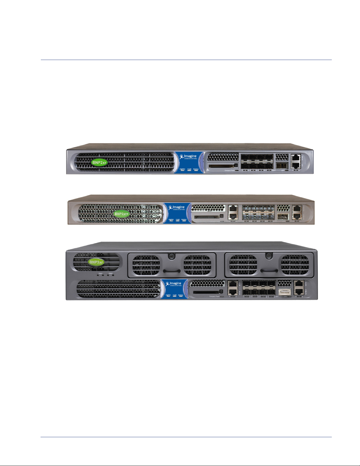
The Selenio ™ Broadcast Network Processor (BNP) products—BNP 2xr, BNP 2xr+, and BNP 3xr—deliver
the industry's highest density digital video solution for grooming, statistical multiplexing, transrating,
digital program insertion (DPI). Additionally, the BNP 3xr, features incorporation of DVB Conditional
Access for program encryption. Each model features a flexible, scalable and modular platform that
simplifies and expedites deployments of advanced video services, simplifies operation and
management, and reduces operational and capital costs.
Figure 1. BNP 2xr
Figure 2. BNP 2xr+
Introduction
Figure 3. BNP 3xr
Receiving input through its Gigabit Ethernet or ASI interfaces, the BNP can statistically multiplex while
performing grooming and digital ad and overlay insertion.The BNP can receive both standard
definition (SD) and high definition (HD) program services, and can concurrently groom and insert
digital ads within the same box while providing program-level encryption in the BNP 3xr.
The BNP is fully MPEG compliant and interoperable with leading cable industry equipment. The 3xr
fers hot-swappable redundant fan modules and power supplies.
unit of
The BNP simplifies configura
accessed through a standard Web browser. Configuration can be performed through SNMP using any
standard network management application. The SNMP MIBs are readily available from the BNP home
page.
tion by providing a Java-based graphical user interface that can be
SelenioTM BNP User Guide, Release 3.7.1 10

Introduction - Document Organization
Document Organization
This guide is organized as follows:
• Chapter 1, "Introduction," (this chapter) describes the contents and conventions used in this guide.
• Chapter 2, "Overview," provides a detailed description of the BNP and its features.
• Chapter 3, "BNP Element Manager Basics," introduces the BNP Element Manager GUI you use to
configure and manage the BNP.
• Chapter 4, "System Configuration," describes the initial product setup and product configuration
using the Java-based BNP Element Manager.
• Chapter 5, "System Redundancy," describes how to set up a pair of BNPs for redundant operations.
• Chapter 6, "Grooming and PSIP," shows you how to set up grooming, transrating, and other
configuration and operational procedures.
• Chapter 7, "Maintenance," contains guidelines for using the Maintenance menu options from the
BNP Element Manager.
• Chapter 8, "Digital Program Insertion (DPI)," describes DPI using the BNP.
• Chapter 9, "DVB Conditional Access," describes how to set up DVP-CA system using the BNP.
• Chapter 10, "ETV Binary Interchange Format," provides an overview of EBIF and typical use cases
for configuration.
• Chapter 11, "Monitoring Alarms and Events," discusses the methods used to monitor the health of
the BNP and its status in the network.
• Chapter A, "Editing the DVB NIT Table," shows you how to edit, make additions to, and delete items
from the NIT table, one of the DVB tables.
• The glossary and index can be used to quickly reference information.
Document Audience
This guide is for system administrators and operators who are responsible for installation and
maintenance of the BNP and for processing network broadcast. You should be familiar with general
video and networking terminology, and should be familiar with basic installation of hardware.
Most importantly, you must be familiar with the basics and principles of broadcast network processing.
Related Documentation
• BNP 2xr Hardware and Installation Reference
• BNP 2xr Quickstart
• BNP2xr+ Hardware and Installation Reference
• BNP 2xr+ Quickstart
• BNP 3xr Hardware and Installation Reference
• BNP 3xr Quickstart
• BNP Release Notes
SelenioTM BNP User Guide, Release 3.7.1 11
Introduction - Document Conventions
Document Conventions
Table 1 provides an easy way to recognize information of particular importance in this manual.
Ta bl e 1 . D oc u me n t C on ve nt io ns
When
you see: It means:
Note: This points out information that may not be part of the text but provide tips and other
helpful advice.
Caution: This provides an alert to an action that may have undesirable consequences if the
instructions are not followed correctly. Cautions also indicate that failure to follow guidelines could
cause damage to equipment or loss of data.
Warning! This shows that failure to take the necessary precautions or to follow guidelines could
cause harm to equipment and personnel.
Navigation tip: follow the path alongside the pointer to navigate to a specific option. Because
many functions can be accessed via various methods, this section provides navigation
information associated with the GUI menus and, as applicable, quick keys and toolbar icons.
Clicking any blue link takes you to the item to which the link refers.
Graphics Used
In some cases, the screens shown in this manual may have been slightly modified after the manual was
released, or may appear slightly different on different browsers.
All efforts have been made to ensure that the latest ima
described is current at the time of writing.
ges are used. In all cases, the functionality
SelenioTM BNP User Guide, Release 3.7.1 12

CHAPTER 2
Overview
This chapter provides a functional overview of the Selenio ™ Broadcast Network Processors (BNPs).
In This Chapter:
• "Product Overview,” next.
• “Product Features” on page 14.
• “BNP Applications” on page 15.
• “BNP Deployment Architecture” on page 17.
• “Redundancy” on page 20.
Product Overview
The BNP product suite consists of the BNP 3xr, BNP 2xr, and BNP2xr+, each of which is managed by
using its BNP Element Manager GUI. All BNP devices provide support for ASI2 hardware modules, and
the following functions:
• Support of both standard definition (SD) and high definition (HD) program services in either
MPEG-2 or H.264 encoding; the BNP simultaneously grooms and inserts digital ads.
• High density video transrating (rate shaping), statistical multiplexing, grooming and digital
program insertion (DPI); transrating video streams with impressively high video quality.
• Multiple levels of redundancy support including service level and 1:1 chassis level redundancy.
• Support for up to eight Gigabit Ethernet (GigE) interfaces for video input or output, as well as up to
18 asynchronous serial interface (ASI) I/O ports in a single rack unit device.
Ta bl e 2 . C om p ar i ng BN P s
BNP
Model
2xr 1RU (rack unit) device that contains Gigabit Proces
2xr+
3xr
Characteristics
hardware modules.
1RU device that contains Gigabit Processor-3 (GBP3) and Processor-3 (PROC3) hardware
modules.
2RU device that contains the BNP 3xr contain Gigabit Processor-3 (GBP3) and Processor3 (PROC3) hardware modules. This BNP also provides hot-swappable redundant fan
modules and power supplies.
Support for DVB Conditional Access (CA) common scrambling algorithm—which is
configurable with the BNP Element Manager, for encryption of programs processed by
the BNP 3xr.
sor-2 (GBP2) and Processor-2 (PROC2)
SelenioTM BNP User Guide, Release 3.7.1 13

Overview - Product Features
Product Features
Applicable Platforms: Any BNP device.
• Based on proprietary flexible Video Intelligence Architecture™ (VIA).
• A graphical user interface for easy configuration and management.
• Eight GigE interfaces standard and up to 18 optional ASI ports.
• Management via two 10/100BaseT Ethernet ports
• Ability to process and encrypt MPEG-2 and H.264 program streams over any of its Gigabit Ethernet
or ASI inputs, and route them to any of these interfaces.
• Seamless digital ad insertion and program substitution.
• Fully interoperable ad insertion with SeaChange, Arris, and other industry standard ad servers.
• Graphic overlay insertions anywhere on a program (MPEG-2) using the BNP GUI to import
standard graphic files (PNG).
• International Time Zones.
• Interface to Event Information Scheduler (EIS), Entitlement Control Message Generator (ECMG) and
Entitlement Management Message Generator (EMMG).
• Support for:
- ATSC and DVB content, including ability to configure and pass through both long and short
names for ATSC TS output programs.
- EBIF
- “FAT” ASI transport services, multiple program groups over a single TS / ASI interface.
- H.264 grooming and multiplexing in a MPEG-2 TS format.
- Language-specific GUI.
- Multiple levels of redundancy at the chassis, input stream, service (program), and Ethernet port
level.
- Operator-generated text and graphic messages from the BNP GUI based on digital overlay
technology.
- Program substitution of a primary network source with a secondary source based on SCTE 30
control.
- RADIUS/TACACS+ authentication.
- Scheduling for Logo Overlay and Operator Messaging up to one month in advance.
- SCTE 18 Digital Emergency Alert Messaging (EAS), which is used to integrate the BNP with EAS
management systems to control the playout of message crawls and audio during an
emergency alert event.
SCTE 21 to SCTE 20 closed caption conversion.
Full compliance with the SCTE 30 and SCTE 35 standards.
Applicable Platform: BNP 3xr
• Incorporation og DVB Conditional Access common scrambling algorithm (CSA), compliant with
DVB CSA and DVB SimulCrypt protocols.
• Bandwidth-based DVB-CA licensing support.
• Dedicated 10/100 BaseT IP management interface for DVB CA encryption.
SelenioTM BNP User Guide, Release 3.7.1 14

Overview - BNP Applications
CNN
Avail
CNN
Ford
CNN
BMW
CNN
Toyota
=RQH
=RQH
=RQH
'3,$G6HUYHUV
ZLWK$G&RQWHQW
6&7(
6&7(
6SOLFH&XHV
Ford
BMW
Toyota
6SOLFHG$GV
B N P
BNP Applications
The BNP delivers the industry’s highest density digital video processing solution for a variety of
applications, some of which are described in the following topics:
• "Grooming, Transrating and Multiplexing,” next.
• “DPI-Based Ad Splicing” on page 15.
• “Messaging System Applications” on page 16.
• “DVB Conditional Access (DVB-CA) Encryption” on page 17 (for BNP 2xr+ and 3xr).
Grooming, Transrating and Multiplexing
Using proprietary Video Intelligence Architecture™ (VIA), the BNP provides the ability to transrate
program streams with the highest quality is unsurpassed in the industry. The BNP seamlessly grooms
multi-program transport streams (MPTS / MUX) and single-program transport streams (SPTS) on both
input and output ports. It also offers multiple Quality of Service (QoS) priority levels on any MPEG-2
program stream enabling selection of the desired level of transrating.
DPI-Based Ad Splicing
The BNP can concurrently groom and seamlessly splice both SD and HD program streams encoded in
either MPEG-2 or H.264 formats. This grooming and splicing capability eliminates the need to dedicate
multiple devices for different functions. The simplified installation, wiring and configuration reduces
system deployment time. The BNP is fully compliant with SCTE 30 and SCTE 35 standards and is
interoperable with the
perform SCTE 30 to SCTE 35 conversion to support digital ad insertion at the hub. The BNP is an ideal
solution
zoned and targeted ad insertion.
A BNP deployed in a cable digital broadcast vide
Figure 4.
Figure 4. Regional Ad Zone Insertion
for both centrally located DPI systems at the headend facility, distributed DPI systems, and
leading digital program insertion (DPI) ad servers. This flexible product can also
o grooming and ad insertion environment is shown in
SelenioTM BNP User Guide, Release 3.7.1 15
Overview - BNP Applications
RGB
Broadcast Network Processor
Digital Encoder
QAM Modulator
Baseband
Audio
Baseband
Video
Digital
Video Services
SCTE-18
Messaging
(cont ains Text Crawl )
Digital EAS
Audio &
Video
Digital Video
Services with
EAS Text Crawl
and
Audio Override
NTSC
Modulated
Channels
GigE
10BT
GigE
GigE
EAS
ENDEC
(SC TE-18
Compliant)
Digital Decoder and
Modulator
GigE
GigE
QAM
Modulated
Channels
B N P
Messaging System Applications
BNP support for messaging system applications is described in the following topics:
• Digital EAS and Operator / Advanced Messaging.
• Graphic Overlay Insertion.
Digital EAS and Operator / Advanced Messaging
Leveraging its existing high-density video processing technology, the BNP’s digital Messaging System
capability allows operators to program both digital SCTE 18 Emergency Alert System (EAS) alerts and
operator-gen
files into the operator crawl message. EAS and Operator / Advanced Messaging alerts are delivered
universally throughout the network, overcoming existing challenges that cable operators face in
supporting analog and digital subscribers with an increasing range of decoding technologies.
erated messages. The Advanced Messaging option allows importing graphics and text
The BNP’s Messaging System support can be applied select
ively to any MPEG-2 program being
processed. EAS and operator-generated messages are digitally rendered and overlaid directly onto a
program, delivered directly to any digital subscriber set-top box or to analog decoders, and presented
as an overlay alert crawl to viewers. The BNP also supports operator-configurable audio override or
audio stream insertion to complement the text crawl message generated by industry-leading EAS
management vendors for a completely customizable deployment.
A BNP in an SCTE 18 digital EAS application is shown in Figure 5.
Figure 5. BNP in SCTE 18 Digital EAS Application
Graphic Overlay Insertion
In addition to EAS and operator messaging, the BNP Messaging System Logo Overlay option supports
insertion of graphic overlays into any MPEG-2 program being processed. Graphic overlays are based on
importing static graphic Portable Network Graphics (PNG) files. Importing text files is also supported,
meaning that customers can create a library of graphic and text files to routinely use (see workflow
example below). You can preview the imported PNG files before starting the overlay insertion.
The location of the insertion is configurable with p
by (x,y) screen coordinates based on pixels relating to program resolution (e.g., SD and HD). Logo
overlay files can be created with PNG alpha channels to control transparency effects supported by the
BNP during the insertion of the overlay. Additionally, background transparency support is available for
non-ascii text overlays in order to support foreign markets.
SelenioTM BNP User Guide, Release 3.7.1 16
ositioning anywhere on the display screen defined
Overview - BNP Deployment Architecture
BNP
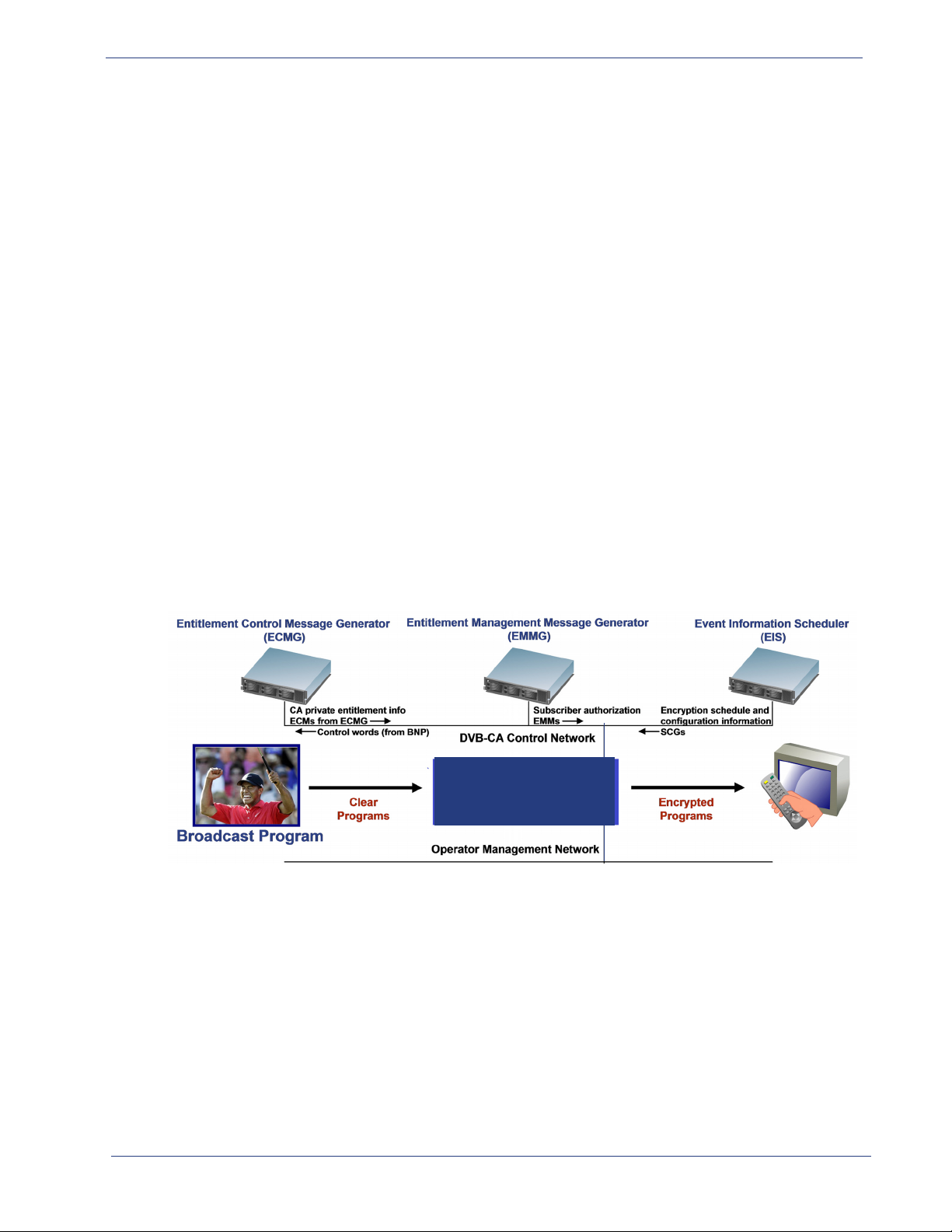
DVB Conditional Access (DVB-CA) Encryption
Applicable Platform: BNP 3xr
The BNP 3xr supports the DVB-CA comm
H.264 programs. The embedded SimulCrypt Engine is a low cost, high density, scalable encryption and
management control implementation that is fully DVB-CA compliant.
on scrambling algorithm (CSA) for encryption of MPEG-2 and
The DVB-CA encryption feature includes the
following functionalities:
• SimulCrypt Synchronization (SCS).
• Control Word Generation (CWG).
• Common Scrambling Algorithm (CSA).
• ECM / EMM insertion.
• CA-related PSI / SI generation and insertion.
• SimulCrypt EIS Lite GUI configuration and management.
RGB’s SimulCrypt engine interfaces with the following external devices:
• Event Information Scheduler (EIS).
• Entitlement Control Message Generator (ECMG).
• Entitlement Management Message Generator (EMMG).
Figure 6 shows the BNP in a D
Figure 6. BNP in a DVB-CA Network
VB-CA network.
BNP Deployment Architecture
The BNP’s modular and programmable platform is designed to provide operators with full processing
scalability to meet their specific processing requirements. The program density of the BNP is softwareconfigurable and upgradeable, allowing operators to start at lower densities and upgrade to the full
hardware capacity through software licenses as their stream densities and network needs grow.
SelenioTM BNP User Guide, Release 3.7.1 17
Overview - BNP Deployment Architecture
B N P
This scalability reduces capital costs and allows operators to allocate budgets accordingly. By paying for
processing on an as needed basis, operators can wisely plan budgets based on today’s requirements
and avoid over-allocation to meet future needs. The programmable and upgradeable architecture of
the BNP, as well as its high processing power, eliminates hardware changes and will simplify and
expedite future deployments of new video processing applications.
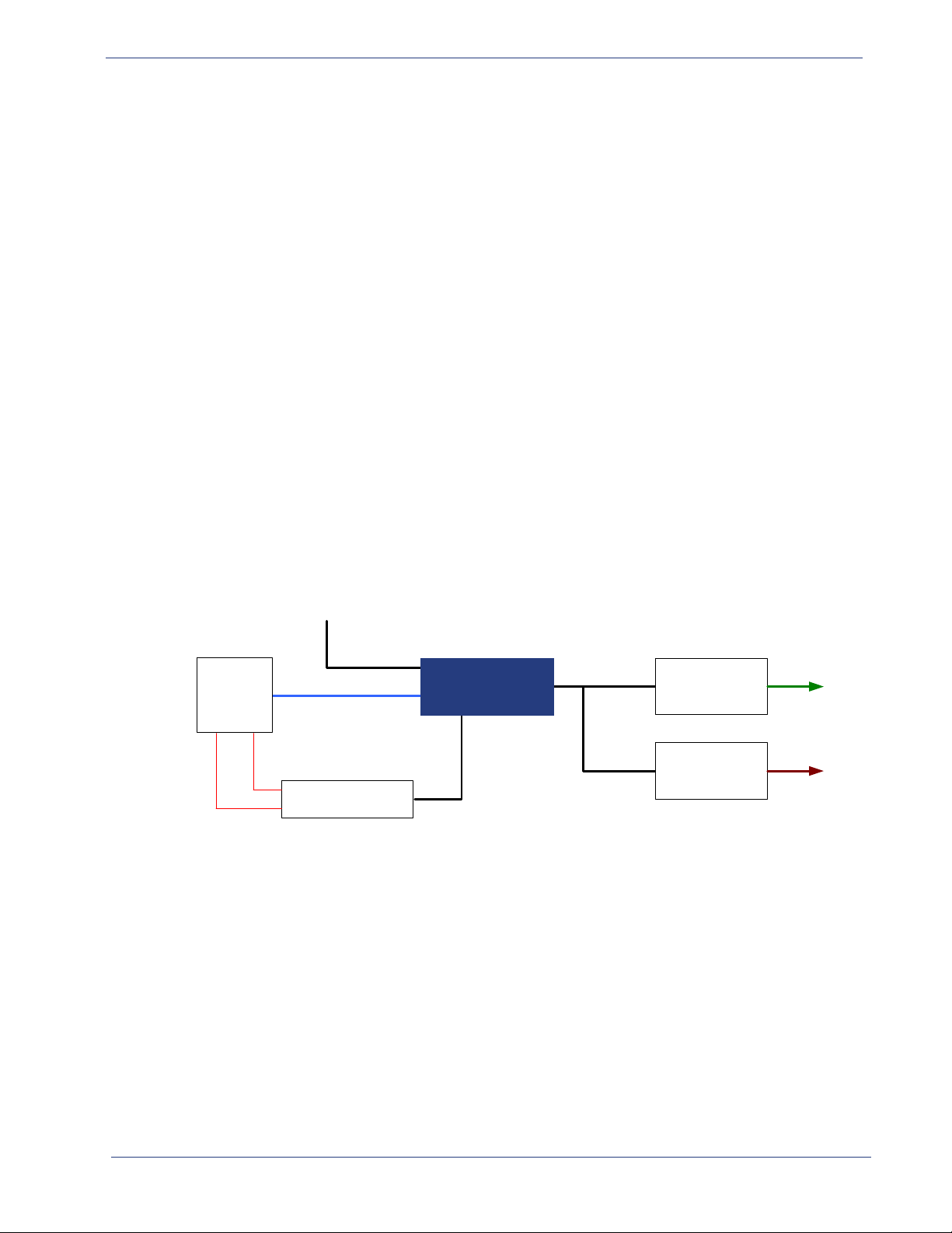
The BNP supports both ASI and
Gigabit Ethernet interfaces, allowing operators who deploy Gigabit
Ethernet networks to profit from the increased cost-efficiency offered with this transport, while still
providing support for operators with legacy ASI networks. This flexibility enables operators with ASI
networks to continue with their existing infrastructures while providing an upgrade path for a future
transition to an IP-based network.
The BNP has eight Gigabit Ethernet interfaces and is scalable to
support up to 18 ASI interfaces using
up to three ASI modules. The Gigabit Ethernet interfaces are part of the BNP’s base configuration and
no additional hardware or licensing is required to utilize these ports. Providing added flexibility, each
ASI interface is software configurable as input or output by using an easy-to-use graphical user
interface.
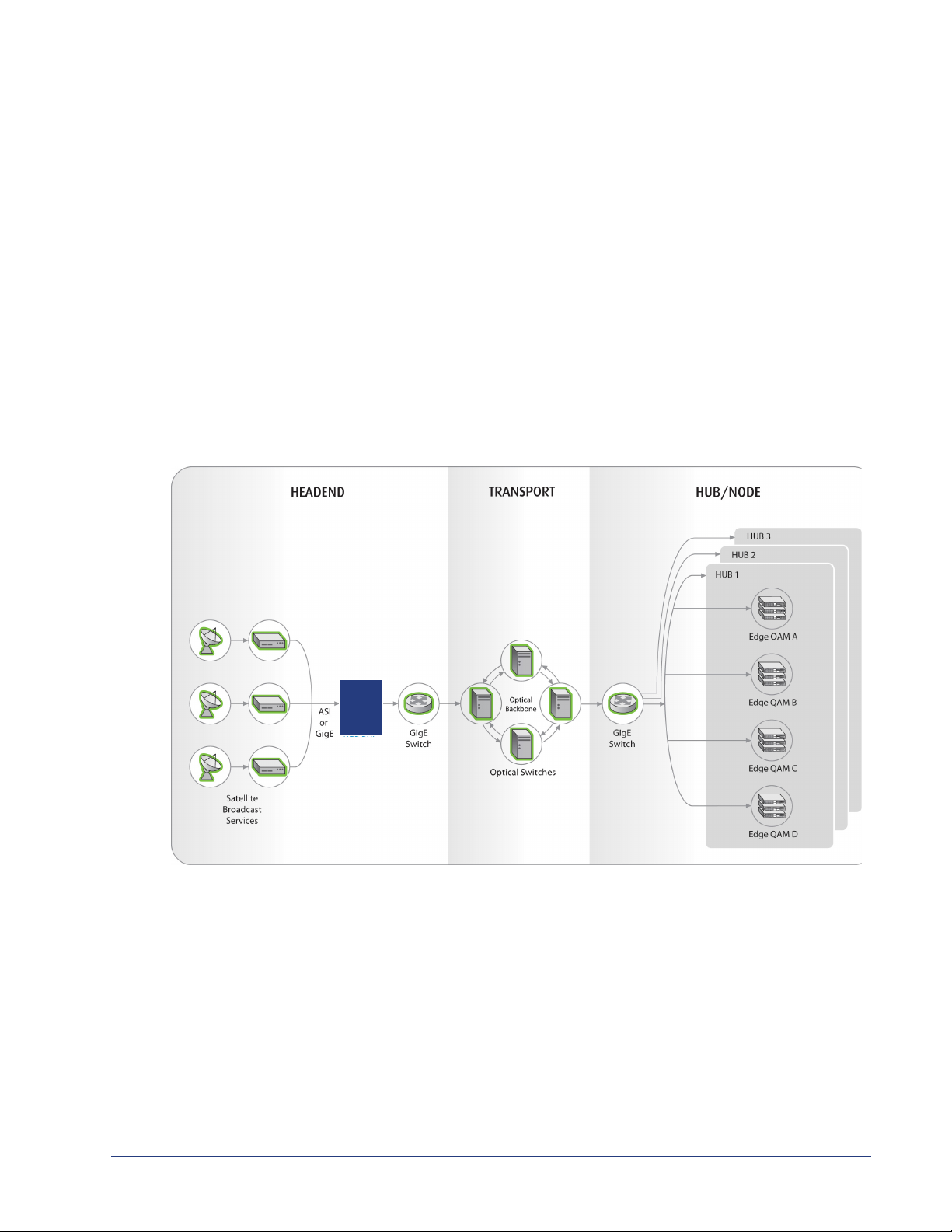
Figure 7. Example of BNP Grooming of GigE or ASI Input Over GigE Transport Network
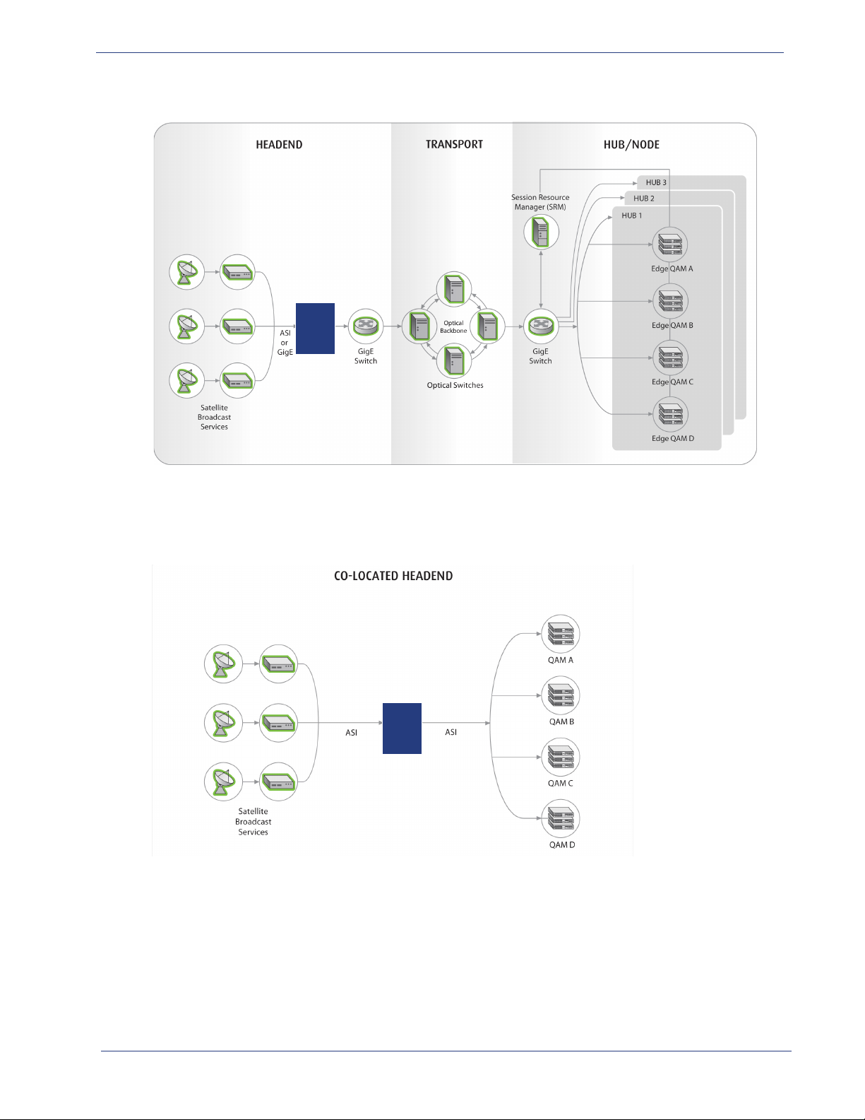
A BNP deployed for bulk rate capping in a Switched Digital Video (SDV) architecture is shown in
Figure 8.
SelenioTM BNP User Guide, Release 3.7.1 18
Overview - BNP Deployment Architecture
B N P
B N P
Figure 8. Example of SDV Architecture over GigE Transport Network
Figure 9 shows how the BNP fits within the network for a centralized system architecture using ASI
interfaces. GigE interfaces could also be used for both input and
output in a co-located headend
application.
Figure 9. Example of Co-Located ASI Architecture
Either ASI or GigE interfaces are used for MPEG input or output. Because of the distance, GigE
interfaces are typically used for transport between the headend and the hub/node.
SelenioTM BNP User Guide, Release 3.7.1 19

Overview - Redundancy
Redundancy
Since a single BNP may deliver advanced video services to tens or even thousands of subscribers in a
video network, it is critical that the BNP provide a high availability of services. To achieve such reliability,
the BNP supports a multi-level redundancy feature to ensure service availability and reduce system
downtime. With proper configuration, the BNP can provide full chassis-level redundancy. On the
hardware level, a BNP provides fan, power, and chassis redundancy; on the software level, the BNP
Gigabit Ethernet port redundancy and a configurable program service redundancy feature.
Four user-configurable redundancy options are supported by the BNP:
• Source Specific Multicast (SSM) Redundancy
• Program Redundancy
• Port Redundancy
• 1:1 Chassis Redundancy
The first three redundancies—SSM, Program, and Port—operate within a single BNP chassis. The
fourth—1:1 Chassis Redundancy—makes use of two BNP chassis. The redundancy for hot-swappable
fan trays and power supply modules happens automatically.
Source Specific Muliticast (SSM) Redundancy
The BNP supports the configuration of up to four source IP addresses per multicast input TS. The BNP
will join one of the four source specific multicasts, when configured. When the input PAT from the
current source times out, then BNP will switch to another source configured for that input TS. All the
streams coming from various sources must be identical (PIDs, program numbers, number of programs
etc.). Therefore, it does not matter which source specific multicast the BNP joins and receives program
information from at any given instance. Also, there is no priority associated with configured sources.
BNP achieves source redundancy using IGMPv3 SSM joins and leave messages. When SSM redundancy
is configured for an input TS, the BNP joins the first configured source specific multicast and waits a
maximum of two seconds for the reception of the PAT. If the PAT is not received in two seconds, then
BNP joins the next configured SSM and repeats the process until it receives a PAT. Video could be
interrupted for up to three seconds (in worst case).
SSM redundancy cannot be coupled with program redundancy on the same input TS.
Because SSM Redundancy requires IGMPv3, the router/switch connected to the GigE port of the input
transport stream must have IGMPv3 enabled.
For information on configuring SSM redundancy, refer to “Creating Input Transport Streams” on
page 109.
Program Redundancy
The BNP supports program redundancy, which is sometimes referred to as service-level redundancy.
For this type of redundancy, when the primary program is gone, the BNP automatically switches to a
redundant or backup program. If any elementary streams are missing from one of the ports, the BNP
switches to the secondary port.
In a program redundancy configuration, a switch to backup occurs when:
• Missing MPTS/SPTS streams are identified by checking the PAT.
SelenioTM BNP User Guide, Release 3.7.1 20

Overview - Redundancy
• Missing program streams are identified by checking the PMT.
• A missing video stream is detected.
You can assign a backup program for every program, and any program can be assigned to back up a
running primary program. The backup program can be another program on the same GigE port or it
can be on a different GigE port in the same chassis.
Program-level redundancy is supported such that when there is a groomed program missing, a
designated input program can function as a standby program and will take over for the missing
program. The detection of a PAT / PMT missing for over 2 seconds is used as the threshold for the
detection of the missing input program.
A program in an input TS that has SSM redundancy configured cannot be used as a backup program
for program redundancy.
For information about Program Redundancy configuration, see “Program Redundancy” on page 152.
Port Redundancy
The BNP supports Gigabit Ethernet port output mirroring within the same chassis. The mirrored port
serves as a standby port in case the primary port fails. The mirroring port must have a unique
IP
address configured. The BNP delivers identical streams to both the primary port and the mirrored
port with the same destination IP address and port number, but a different source IP address.
The multiplexes output on one GigE are delivered to the mirrored GigE port simultaneously as a fully
operational, redundant output GigE port. Regardless of mirroring, all active GigE ports must have
unique IP addresses assigned.
To set GigE port-level redundancy, see “GigE Port Configuration” on page 44.
1:1 Chassis-level Redundancy
When the ports and global settings are configured to do so, the BNP provides 1:1 redundancy. The BNP
supports hot-standby 1:1 chassis redundancy through heartbeat and virtual IP failover mechanisms.
Heartbeats provide the ability to synchronize failover to a secondary BNP. A heartbeat daemon on the
primary unit will send out unicast heartbeat messages every 250 milliseconds.The heartbeat daemon
running on the standby BNP listens to the heartbeats coming from the primary BNP. If the standby BNP
does not hear the primary BNP’s, it initiates a failover and takes ownership. The heartbeat daemon
running on the standby BNP checks for heartbeats coming from the primary BNP over both the normal
Ethernet 10/100BaseT management connection and optionally the eighth Gigabit Ethernet port (GigE
8) connection (when used as a backup to the Ethernet 10/100BaseT management port).
The Backup LED on the front of the chassis indicates the redundancy role of a chassis: green indicates
the active chassis, and orange indicates a standby chassis.
The standby chassis takes over if the primary (active) chassis fails, if there is a system or module
overheat, failed fan, failed power supply, or missing heartbeat from the primary unit. The former
standby (now the active) chassis now becomes configurable through the BNP Element Manager.
SelenioTM BNP User Guide, Release 3.7.1 21
Overview - Redundancy
GigE
Switch/Router
10/100BaseT
Switch/Router
Media
IP Transport
Network
Control
IP Network
GigE8
Heartbeats
10/100BaseT Heartbeats
Port 10/100BaseT
192.168.21.1
Port GigE8
10.1.1.1
Port GigE8
10.1.1.2
Port 10/100BaseT
192.168.21.2
virtual IP addresses
for GigE1-Gig7
192.168.2.1
192.168.2.2
192.168.2.3
192.168.2.4
192.168.2.5
192.168.2.6
192.168.2.7
virtual IP address
for 10/100BaseT
192.168.21.200
Virtual IP addressing is used to support the BNP 1:1 chassis redundancy feature. If the active chassis
fails, the standby assumes the virtual IP address. Network devices communicate with the virtual
IP addresses, not to the physical IP addresses. If the i
setting is automatically synchronized to the standby chassis.
nput/output of the active chassis changes, the new
GigE 8 can be configured to send heartbeat messages
in the initial setting. If the network Ethernet 10/
100 management connection is unplugged, the active chassis remains active. If the input or output
GigE link is down, the active chassis shows a hardware fault and becomes the standby.
The standby chassis does not have any separate licenses. The license
usage on the active and standby
chassis is always synchronized; if the standby chassis becomes the active chassis, it assumes the
licenses of the active chassis.
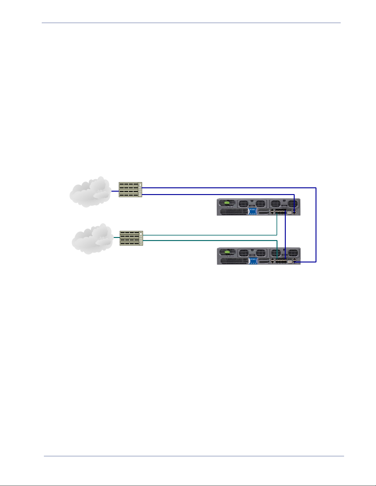
Figure 10 illustrates a typical configuration scenario of the BNP hot-standby 1:1 chassis redundancy
feature.
Figure 10. 1:1 Chassis Redundancy using Heartbeat and Virtual IP Failover Mechanism
In this example, the primary BNP has a management IP address of 192.168.21.1 and the secondary BNP
has an address of 192.168.21.2. A third IP address in the same subnet 192.168.21.200 is configured as a
virtual IP address. The video server and management workstation will use this virtual IP address to
communicate to the active BNP unit. During the normal course of operation, the primary BNP assumes
the virtual IP address and acts as the active unit. When a failover event happens, the secondary BNP will
take ownership of the virtual IP address and assume the active role. It achieves this by sending an ARP
request to associate the MAC addresses of the secondary ports with the virtual IP addresses.
For information about 1:1 chassis re
dundancy configuration, see “1:1 Redundancy Best Practices and
Considerations” on page 94.
SelenioTM BNP User Guide, Release 3.7.1 22

CHAPTER 3
BNP Element Manager Basics
This chapter provides information about the Selenio ™ BNP Element Manager, which is used to
configure and monitor the Broadcast Network Processor (BNP).
In This Chapter:
• “BNP Element Manager Overview,” next.
• “Obtaining Java Runtime Environment” on page 24.
• “Broadcast Network Processor Home Page” on page 24.
• “BNP Element Manager GUI” on page 26.
• “Grooming Tab” on page 30.
• “Alarms & Events tab” on page 30.
• “Configuration Tab” on page 31.
• “Chassis Tab” on page 31.
• “BNP Version Information” on page 33.
• “Quick Keys” on page 35.
BNP Element Manager Overview
The BNP Element Manager is a Java-based GUI available using a standard web browser, which offers a
variety of features intended to simplify the setup and operation of the BNP:
• An embedded GUI application for configuration and management via XML/RPC over HTTP.
• Program level drag and drop grooming.
• PID Management.
• Input program redundancy.
• Output port mirroring.
• Simultaneous bitrate analysis of input and output transport streams and programs.
• Viewing of alarm and event logs.
• Module redundancy configurations.
• Full configuration of system functions and Gigabit Ethernet ports.
SelenioTM BNP User Guide, Release 3.7.1 23

BNP Element Manager Basics - Obtaining Java Runtime Environment
Obtaining Java Runtime Environment
The BNP Element Manager requires that the PC on which it is running have Java™ Runtime Environment
(JRE) v1.6 or higher. If your PC does not have the correct JRE installed, it is available free from the
Imagine Communications Customer Portal.
To obtain installation instructions and the latest version of JRE that is compatible with the BNP Element
Manager, log in to Imagine Communications Customer Portal and search for Downlo
Environment.
Broadcast Network Processor Home Page
The BNP Element Manager software is pre-installed on the BNP at the factory and is presented as a
home page (Figure 11) following entry of a BNP’s network address from
providing access to the BNP El
(Figure 11 and Table 3).
ement Manger, several other tools are accessible from the home page
ad Java Runtime
a web browser. In addition to
Figure 11. BNP Home Page
Ta bl e 3 . B ro a dc a st Ne t wo r k P ro c es s or Ho me P a ge Op t io n s
Link Option Description
Launch BNP Element Manager Click to start the launch, which will present the login dialog prior to
ing the BNP Element Manager screen.
reveal
Download Java SDK Quick-access to the Oracle website, if you need to download the
recommend
Show System Log View events and error messages recorded by the BNP.
Show Build Info View the current software version number and build number.
SNMP Mib Files Access and save or open the MIB files for the current BNP release.
ed version of the Java SDK to your desktop.
SelenioTM BNP User Guide, Release 3.7.1 24

BNP Element Manager Basics - Broadcast Network Processor Home Page
Ta bl e 3 . B ro a dc a st Ne tw or k P r oc e ss or H o me P ag e O p ti o ns (C on ti n ue d )
Link Option Description
System Configuration Files Access the .cfg files associated with the current BNP release.
Collect Diagnostic Info for Tech
port
Sup
Collect Quick Diagnostic Info for
Support
Te ch
Generate complete diagnostic files that can be provided to RGB
Customer Support about your BNP system.
Generate the short system diagnostic file set.
Log in and Access the BNP Element Manager
1. Open a web browser from the management workstation and enter the IP address of the BNP in the
browser’s address field to display the BNP Element Manager home page.
2. Click Launch BN
Element Manager Log in dialog is now presented for
local login (shown) or login via AAA.
For login with AAA, additional
the login screen, for entry of SNMP read/write strings
(see also “Changing the SNMP Community String” on
page 193).
3. Enter login
- At IP Address or Host Name: enter the IP
address of the BNP to manage, or use that already
provided in this field.
- At User: select the user account from the drop-
down list. If using an AAA server for
authentication, the drop-down list is not
available— you will need to type the user name in this field. (Table 4, and Table 21 on page 50).
- At the Password: field, type the password string. Note that passwords are case sensitive.
P Element Manager. The BNP
fields are provided in
parameters:
Ta bl e 4 . BNP Element Manager User Accounts
User Password Privileges
Administrator Admin Unrestricted access and ability to change password. This level of
ss is typically used only by Field Application Engineers and
acce
Te ch n ic a l S up p or t p e rs on ne l . H ow ev er , t hi s a cc es s c a n b e
granted to head-end personnel in your organization.
Operator Operator Read-write access that allows config
typical login level.
User User Read-only access. This user account cannot modify BNP
figuration.
con
uration changes. This is the
4. Click Log in.
Successful login presents the Groo
SelenioTM BNP User Guide, Release 3.7.1 25
ming-Mapping tab screen (Figure 13).
BNP Element Manager Basics - BNP Element Manager GUI
Broadcast Ne twork Proce ssor
ElementManager Window
Tabs
Groom ing
Alarms & Events
Configuration
Chassis
Global
Ethernet Control Port
GigE Po rts
ASI Ports
User Authentication
Messaging System
SNMP Trap
Mapping
Input B itrate Mo nitor
Input ‐Output Bitrate Monitor
Status
Monitor
About
Menu
F
ile View Maintenance H elp
Ex
it
R
efresh Current
Scree n
License Manager
Software U
pgrade
C
hange SNMP Community
String
Set Up N
etwork Information
Table (NIT )
Set
Up Time Offset Table (TOT)
System Shutdown
Expand Mappings
Collapse Mappings
Reboot
R
emove Chassis Redundancy
Reg
room
Search...
CA Systems
SCG
DVB-CA
D
VB-CA
Global Configuration
2xr+ and 3xr
S
tatus
System DPI
A
ctivity
2xr+ an d 3xr
Force r e‐allocation o f TS
Logging Off
Use the Exit option to log off gracefully from your BNP Element Manager session.
Menu Path
From the BNP Ele
or use quick keys: Alt f, Alt e
ment Manager main menu -> File -> Exit.
The BNP screen is now dismissed. Use steps provided in “Log in and Access the BNP Element Manager”
on page 25 to initiate another session.
BNP Element Manager GUI
The BNP Element Manager provides a convenient, intuitive method for management of a BNP. In
addition to numerous tools built into the interface for configuration of services, status of the BNP
system is always displayed at the bottom border of the Element Manager screen. You can navigate to
the various functions by selecting options from the tabs and menus, and menu items are associated
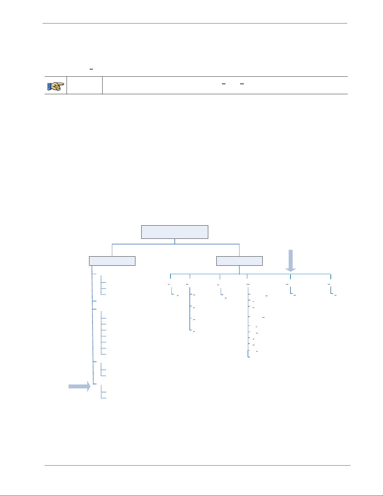
with keyboard mnemonics for quck access (Figure 12).
Figure 12. Hierarchy of BNP Element Manager Menus and Tabs
SelenioTM BNP User Guide, Release 3.7.1 26
BNP Element Manager Basics - BNP Element Manager GUI
BNP Element
Manager Menu
Ta b s c re e n
Connectivity
Status (standby
BNP).
IP address and
status of active
BNP.
Alarm Notification
Ta b Bank s
System Name BNP Model IP Address
Login Level
System time
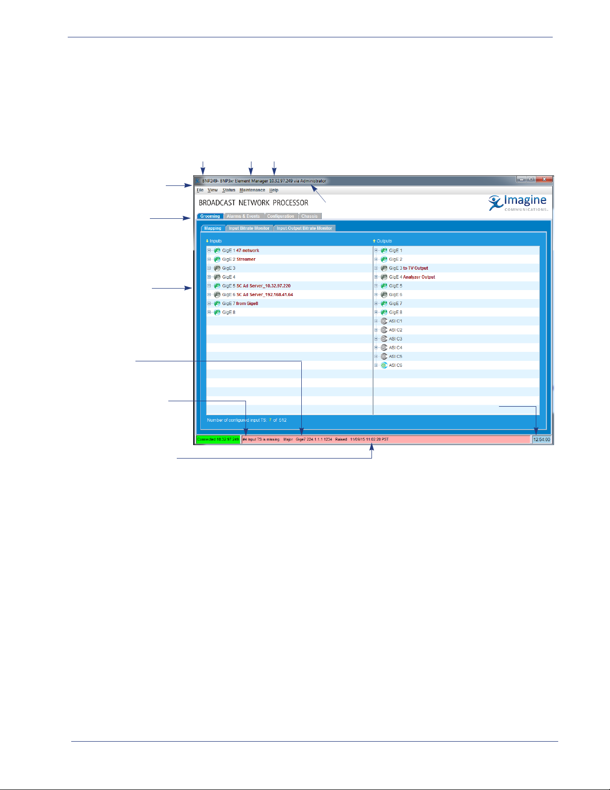
BNP Element Manager Window
The BNP Element Manager provides menus, icons, tabs, and colors in the GUI, which assist in navigating
to configuration functions and determining status of the BNP (Figure 13).
Figure 13. BNP Element Manager GUI Components
Note that the identity of the BNP and the currently logged in user is always in view at the top bar of the
window. Status of the connection between the BNP and the BNP Element Manager is always on display
at the bottom bar, alongside the overall status of the BNP system.
SelenioTM BNP User Guide, Release 3.7.1 27

BNP Element Manager Basics - BNP Element Manager GUI
BNP Element Manager Menus
Use the BNP Element Manager menus (Table 5) to perform tasks listed in Table 6. You can access these
options either by using the pull-down menu, or by combining the Al
particular to a function.
Ta bl e 5 . B NP Element Manager Menus
Menu BNP Purpose
File All Exit the BNP Elemen
View All Refresh the currently active window or
Status All View DPI Activity.
Maintenance All Upgrade software, manage licensing, edit the
or TOT tables, reboot, perform a BNP shutdown, remove BNP redundancy, or
regroom.
DVB-CA 3xr Perform global DVB-CA configuration.
Help All Access the About screen, in which
BNP in use.
t key with the underlined character
t Manager.
control view of mapping.
SNMP community string, set up NIT
to view current release information about the
Ta bl e 6 . BNP Elemen
Menu Description Additional Information
File
(Alt f)
View
(Alt v)
Status Check DPI status and/or summary at the BNP
t Manager Main Menu and Quick Keys
Perform a graceful logout from the BNP Elemen
Manager, with the following option:
•E
xit (Alt x)
Adjust the view in the BNP Element Manager
window, with the following options:
•
Refresh Current Screen (Alt r)
• Expand Mapping (Alt e)
•
Collapse Mapping (Alt c)
tem level.
sys
“BNP Version Information” on page 33.
t
Examples that demonstrate results of
expa
nd and collapse are provided in
Figure 55, “Grooming-Mapping View Collapsed View,” on page 104, and
Figure 57, “View --> Expand Mapping
to View All Contents,” on page 106.
SelenioTM BNP User Guide, Release 3.7.1 28

BNP Element Manager Basics - BNP Element Manager GUI
Ta bl e 6 . B NP Element Manager Main Menu and Quick Keys (Continued)
Menu Description Additional Information
Maintenance
(Alt m)
Help
(Alt h)
Access BNP maintenance functions, with the
following options:
•Upgrade Software
•License Manager “Managing Licenses” on page 190.
•Change SNMP Community String “Changing the SNMP Community
•Set up Network Information Table (NIT) “You will need to log in as described
•Set Up Time Offset Table (TOT) “Configuring the Time Offset Table
•Reboot “Rebooting the System” on page 196.
•System Shutdown “System Shutdown” on page 197.
• Remove Chassis Redundancy “Removing Chassis Redundancy” on
•Regroom “Regrooming” on page 198.
View version information in the About screen,
with the following option:
• About (Alt a)
“Software Upgrade” on page 185.
String” on page 193.
above for any workstation that is
accessing the Element Manager for the
first time after the SNMP Read / Write
Community Strings have been
changed.” on page 194.
(TOT)” on page 194.
page 198.
“BNP Version Information” on page 33.
BNP Element Manager Tabs
Use the BNP Element Manager tabs to perform the configuration, monitoring, grooming tasks listed in
Table 7.
Ta bl e 7 . BNP Element Manager Window Tabs
Tab Use
Grooming Perform mapping tasks, access real-time bitrate mo
Ta b” on pa g e 30
Alarms & Event View real-time lists of alarms and events logged by this BNP. See also Chapter 11,
"Monitoring Alarms and Events" on Page 252.
Configuration Access various configuration parameters via the subtabs labelled Global, Ethernet
ol Port, GigE Ports, ASI Ports, User Authentication, Messaging System, and
Contr
SNMP Trap.See also “Configuration Tab” on page 31
Chassis
Provides a quick overview of the BNP system state. Clicking a car
specific information for that item. Clicking any other part of the BNP displays system
formation about the BNP. See also “Chassis Tab” on page 31.
in
nitoring views. See also “Grooming
d or port provides
SelenioTM BNP User Guide, Release 3.7.1 29

BNP Element Manager Basics - Grooming Tab
BNP Element Manager Status Bar
The status bar at the bottom of the BNP Element Manager always remains in view to report status
information about the BNP. Color coding (Table 8) indicates the current, highest-level severity of the
situation reported for connectivity
Connectivity
Status of connectivity to the BNP is reported at the left portion of the status bar, where you can view
the currently connected IP address of the BNP, and current status of connectivity between the BNP and
the BNP Element Manager as either green (good) or red (error).
Alarms
Status of most critical event reported by the BNP is displayed as a text string and color code (Table 8) in
the middle section of the status bar.
Ta bl e 8 . BNP Element Manager System Status
and alarms.
Color Meaning
Green Informational alert or event.
Yellow Minor alert or event may require operator action.
Pink Major alert or event requires operator action.
Red Critical error has occurred and operator intervention is needed.
Grooming Tab
The Grooming tab screen provides access to the mapping page and the bitrate monitoring pages. For
more information about the Grooming tab, see the following topics:
• “Grooming - Mapping” on page 104.
• “Monitoring Bitrates” on page 182.
Alarms & Events tab
The Alarms & Events tab provides information about the current state of the system and is viewable at
any time. For more information about the Alarms & Event tab, see Chapter 11, “Monitoring Alarms and
Events.”
SelenioTM BNP User Guide, Release 3.7.1 30
 Loading...