

Imagine communications Selenio 6800 HUC6800+C, Selenio 6800 HUC6800 Installation And Operation Manual

Installaon and Operaon Manual
Selenio 6800™
HUC6800+ and HUC6800+C
Broadcast Upconverters
Edion A
175-000293-00
Delivering the Moment

Publicaon Informaon
© 2014 Imagine Communicaons Corp. Proprietary and Condenal.
Imagine Communicaons considers this document and its contents to be proprietary and condenal. Except for
making a reasonable number of copies for your own internal use, you may not reproduce this publicaon, or any part
thereof, in any form, by any method, for any purpose, or in any language other than English without the wrien consent
of Imagine Communicaons. All others uses are illegal.
This publicaon is designed to assist in the use of the product as it exists on the date of publicaon of this manual, and
may not reect the product at the current me or an unknown me in the future. This publicaon does not in any way
warrant descripon accuracy or guarantee the use for the product to which it refers. Imagine Communicaons reserves
the right, without noce to make such changes in equipment, design, specicaons, components, or documentaon as
progress may warrant to improve the performance of the product.
Trademarks
6800+™, ADC™, CCS Navigator™, Channel ONE™, ChannelView™, ClipSync™, Delay™, D Series™, D Series DSX™, Deliver
the Moment™, Delivering the Moment™, FAME™, Farad™, G8™, G Scribe™, HView™, IconMaster™, IconLogo™, IconStaon™, IconKey™, InfoCaster™, InfoCaster Creator™, InfoCaster Manager™, InfoCaster Player™, InstantOnline™, Invenio®,
Live Update™, mCAPTURE™, Magellan™, Magellan CCS Navigator™, Magellan Q SEE™, MulService SDN™, NetPlus™,
NetVX™, NewsForce™, Nexio® G8™, Nexio AMP® ChannelView™, Nexio® Channel ONE™, Nexio® ClipSync™, Nexio®
Delay™, Nexio® Digital Turnaround Processor™, Nexio® Farad™, Nexio® G Scribe™, Nexio® IconKey™, Nexio® IconLogo™,
Nexio® IconMaster™, Nexio® IconStaon™, Nexio® InfoCaster™, Nexio® InfoCaster Creator™, Nexio® InfoCaster Manager™, Nexio® InfoCaster Player™, Nexio® InfoCaster Trac™, Nexio® InstantOnline™, Nexio® mCAPTURE™, Nexio® NewsForce™, Nexio® NXIQ™, Nexio® Playlist™, Nexio® Remote™, Nexio®RTX Net™, Nexio® TitleMoon™, Nexio® TitleOne™,
Nexio® Velocity ESX™, Nexio® Velocity PRX™, Nexio® Velocity XNG™, Nexio® Volt™, OPTO+™, Panacea™, Planum™,
Playlist™, Predator II GRF™, Predator II GX™, Punctuate™, Remote™, RTX Net™, QuiC™, Q SEE™, SD STAR™, Selenio™,
Selenio 6800+™, SelenioNext™, Selenio X50™, Selenio X85™, Selenio X100™, TitleMoon™, TitleOne™, Velocity ESX™,
Velocity PRX™, Velocity XNG™, Versio™, Videotek® SD STAR™, X50™, and X85™ are trademarks of Imagine Communicaons or its subsidiaries.
Altude Express®, Connectus®, Enabling PersonalizedTV®, ICE® Broadcast System, ICE Illustrate®, ICE Q® algorithms, ICEPAC®, Imagine ICE®, Inscriber®, Inscriber® Connectus®, Invenio®, NEO®, Nexio®, Nexio AMP®, PersonalizedTV®, RouterWorks®, Videotek®, Videotek® ASI STAR®, Videotek® GEN STAR®, and Videotek® HD STAR® are registered trademarks of
Imagine Communicaons or its subsidiaries.
Microso® and Windows® are registered trademarks of Microso Corporaon. HD BNC is a trademark of Amphenol
Corporaon. Some products are manufactured under license from Dolby Laboratories. Dolby and the double D symbol
are registered trademarks of Dolby Laboratories. DTS Neural audio products are manufactured under license from DTS
Licensing Limited. DTS and the Symbol are registered trademarks & the DTS Logos are trademarks of DTS, Inc. © 2008
2010 DTS, Inc. All other trademarks and trade names are the property of their respecve companies.
Contact Informaon
Imagine Communicaons has oce locaons around the world. For locaons and contact informaon see:
hp://www.imaginecommunicaons.com/contact us/
Support Contact Informaon
For support contact informaon see:
▪ Support Contacts: hp://www.imaginecommunicaons.com/services/technical support/
▪ eCustomer Portal: hp://support.imaginecommunicaons.com
© 2014 Imagine Communicaons Corp. Proprietary and Condenal

HUC6800+ and
HUC6800+C
Broadcast Upconverters
Installation and Operation Manual
Edition A
July 2006


Contents
Preface
Manual Information .............................................................................. vii
Purpose ........................................................................................... vii
Audience ........................................................................................ vii
Revision History ............................................................................ vii
Writing Conventions .....................................................................viii
Obtaining Documents ................................................................... viii
Unpacking/Shipping Information .......................................................... ix
Unpacking a Product ....................................................................... ix
Product Servicing ............................................................................ ix
Returning a Product ........................................................................ ix
Restriction on Hazardous Substances (RoHS) Compliance ....................x
Waste from Electrical and Electronic Equipment (WEEE) Compliance xi
Safety .................................................................................................... xii
Safety Terms and Symbols in this Manual .................................... xii
Chapter 1: Introduction
Overview ..................................................................................................1
Product Description ..................................................................................2
Main Features ...................................................................................2
Applications ......................................................................................3
Module Description ..................................................................................4
Front Module ....................................................................................4
Back Connectors ...............................................................................6
Signal Flow .......................................................................................6
Chapter 2: Installation
Overview ..................................................................................................9
HUC6800+ Installation and Operation Manual iii

Contents
Maximum 6800+ Frame Power Ratings ............................................... 10
Unpacking the Module .......................................................................... 11
Preparing the Product for Installation ............................................ 11
Checking the Packing List ............................................................. 11
Setting Jumpers ..................................................................................... 12
Installing HUC6800+ and HUC6800+C Modules ............................... 14
Upgrading Module Firmware ................................................................ 15
Upgrading the Firmware ................................................................ 15
Correcting a Failed Upgrading Procedure ..................................... 18
Chapter 3: Operation
Overview ............................................................................................... 23
Operating Notes ..................................................................................... 24
Audio and Video Synchronization and Delay ....................................... 24
Audio Sync and Delay ................................................................... 26
Video Frame Sync and Delay ........................................................ 26
Input and Output Standards ................................................................... 27
Aspect Ratio Conversion ....................................................................... 28
Selecting a Standard Aspect Ratio ................................................. 28
Setting a Custom Aspect Ratio ...................................................... 28
Saving, Selecting, and Recalling Saved Aspect Ratios ................. 30
Overscan Mode .............................................................................. 31
Bypass Mode .................................................................................. 31
Changing Parameter Settings ................................................................ 33
Recalling Default Parameter Settings ............................................ 34
On Screen Display (OSD) Monitoring ........................................... 34
Reading Software and Hardware Versions .................................... 34
Cross-Functional Parameter Changes ............................................ 35
Control Parameters ................................................................................ 36
LEDs and Alarms .................................................................................. 48
Monitoring LEDs ........................................................................... 48
Module Status LEDs ...................................................................... 50
Alarms ............................................................................................ 50
Chapter 4: Specifications
Overview ............................................................................................... 51
Inputs ..................................................................................................... 52
SD/HD-SDI Video ......................................................................... 52
Genlock .......................................................................................... 52
iv HUC6800+ Installation and Operation Manual

Outputs ...................................................................................................53
SD/HD-SDI Reclocked Video ........................................................53
Upconverted HD-SDI Video ..........................................................54
Miscellaneous .........................................................................................55
Audio Delay (Data Out) ..................................................................55
Power Consumption ........................................................................55
Operating Temperature ...................................................................55
Appendix A: Communication and Control
Troubleshooting Tips
Overview ................................................................................................57
General Troubleshooting Steps ..............................................................58
Software Communication and Control Issues ........................................59
+ Pilot Lite Fails to Communicate with Installed Modules ...........59
+ Pilot Lite Does Not Find All Modules in Frame ........................60
+ Pilot Lite or CCS Software Application Not Responding ..........61
+ Pilot Lite Cannot Control a Module Showing
in the Control Window ...................................................................61
+ Pilot Lite Status Bar Reports ‘Not Ready’ ..................................61
CCS Software Application or Remote Control Panel Does Not
Communicate with Module ............................................................62
Alarm Query Fails When a Device Reboots ...................................62
Hardware Communication and Control Issues ......................................63
Frames Fail to Communicate with the PC after a Power Failure ...63
Module Does Not Seem to Work ....................................................63
Contacting Customer Service .................................................................63
Contents
Index
Keywords ...............................................................................................65
HUC6800+ Installation and Operation Manual v

Contents
vi HUC6800+ Installation and Operation Manual

Manual Information
Purpose
This manual details the features, installation, operation, maintenance,
and specifications for the HUC6800+ Broadcast Upconverter.
Preface
Audience
Revision History
This manual is written for engineers, technicians, and operators
responsible for installation, setup, maintenance, and/or operation of the
HUC6800+ Broadcast Upconverter.
Table P-1. Revision History of Manual
Edition Date Comments
A July 2006 Initial release
HUC6800+ Installation and Operation Manual vii
Preface
Writing Conventions
To enhance your understanding, the authors of this manual have
adhered to the following text conventions:
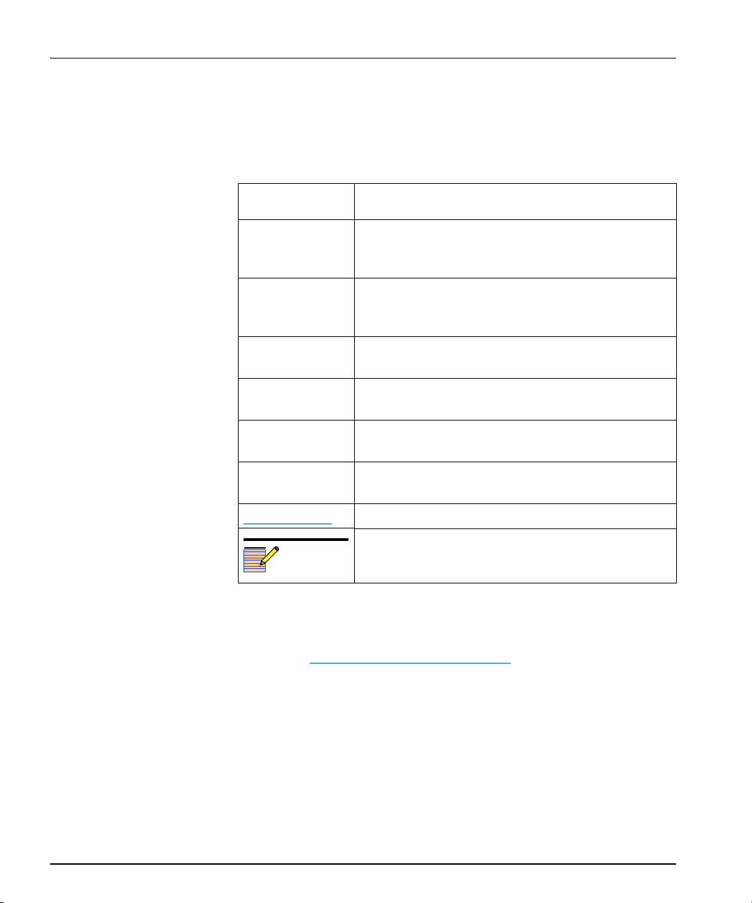
Table P-2. Writing Conventions
Term or
Convention
Bold Indicates dialog boxes, property sheets, fields, buttons,
Italics Indicates E-mail addresses, the names of books or
CAPS Indicates a specific key on the keyboard, such as
Code Indicates variables or command-line entries, such as a
> Indicates the direction of navigation through a hierarchy
hyperlink Indicates a jump to another location within the
Internet address
Note
Description
check boxes, list boxes, combo boxes, menus,
submenus, windows, lists, and selection names
publications, and the first instances of new terms and
specialized words that need emphasis
ENTER, TAB, CTRL, ALT, or DELETE
DOS entry or something you type into a field
of menus and windows
electronic document or elsewhere
Indicates a jump to a Web site or URL
Indicates important information that helps to avoid and
troubleshoot problems
Obtaining Documents
Product support documents can be viewed or downloaded from our
Web site at www.broadcast.harris.com/leitch
Documentation). Alternatively, contact your customer service
representative to request a document.
viii HUC6800+ Installation and Operation Manual
(go to Support>

Unpacking/Shipping Information
Unpacking a Product
This product was carefully inspected, tested, and calibrated before
shipment to ensure years of stable and trouble-free service.
1. Check equipment for any visible damage that may have occurred
during transit.
2. Confirm that you have received all items listed on the packing list.
3. Contact your dealer if any item on the packing list is missing.
4. Contact the carrier if any item is damaged.
5. Remove all packaging material from the product and its associated
components before you install the unit.
Keep at least one set of original packaging, in the event that you need to
return a product for servicing.
Product Servicing
Preface
Except for firmware upgrades, HUC6800+ modules are not designed
for field servicing. All hardware upgrades, modifications, or repairs
require you to return the modules to the Customer Service center.
Returning a Product
In the unlikely event that your product fails to operate properly, please
contact Customer Service to obtain a Return Authorization (RA)
number, then send the unit back for servicing.
Keep at least one set of original packaging in the event that a product
needs to be returned for service. If the original package is not available,
you can supply your own packaging as long as it meets the following
criteria:
• The packaging must be able to withstand the product’s weight.
• The product must be held rigid within the packaging.
• There must be at least 2 in. (5 cm) of space between the product and
• The corners of the product must be protected.
Ship products back to us for servicing prepaid and, if possible, in the
original packaging material. If the product is still within the warranty
period, we will return the product prepaid after servicing.
the container.
HUC6800+ Installation and Operation Manual ix

Preface
Restriction on Hazardous Substances (RoHS) Compliance
Directive 2002/95/EC—commonly known as the European Union (EU)
Restriction on Hazardous Substances (RoHS)—sets limits on the use of
certain substances found in electrical and electronic equipment. The
intent of this legislation is to reduce the amount of hazardous chemicals
that may leach out of landfill sites or otherwise contaminate the
environment during end-of-life recycling. The Directive takes effect on
July 1, 2006, and it refers to the following hazardous substances:
• Lead (Pb)
• Mercury (Hg)
• Cadmium (Cd)
• Hexavalent Chromium (Cr-V1)
• Polybrominated Biphenyls (PBB)
• Polybrominated Diphenyl Ethers (PBDE)
According to this EU Directive, all products sold in the European Union
will be fully RoHS-compliant and “lead-free.” (See our Web site,
www.broadcast.harris.com/leitch
deadlines for compliance.) Spare parts supplied for the repair and
upgrade of equipment sold before July 1, 2006 are exempt from the
legislation. Equipment that complies with the EU directive will be
marked with a RoHS-compliant emblem, as shown in Figure P-1.
Figure P-1. RoHS Compliance Emblem
, for more information on dates and
x HUC6800+ Installation and Operation Manual

Waste from Electrical and Electronic Equipment (WEEE) Compliance
The European Union (EU) Directive 2002/96/EC on Waste from
Electrical and Electronic Equipment (WEEE) deals with the collection,
treatment, recovery, and recycling of electrical and electronic waste
products. The objective of the WEEE Directive is to assign the
responsibility for the disposal of associated hazardous waste to either
the producers or users of these products. Effective August 13, 2005,
producers or users will be required to recycle electrical and electronic
equipment at end of its useful life, and may not dispose of the
equipment in landfills or by using other unapproved methods. (Some
EU member states may have different deadlines.)
In accordance with this EU Directive, companies selling electric or
electronic devices in the EU will affix labels indicating that such
products must be properly recycled. (See our Web site,
www.broadcast.harris.com/leitch
deadlines for compliance.) Contact your local sales representative for
information on returning these products for recycling. Equipment that
complies with the EU directive will be marked with a WEEE-compliant
emblem, as shown in Figure P-2.
, for more information on dates and
Preface
Figure P-2. WEEE Compliance Emblem
HUC6800+ Installation and Operation Manual xi
Preface
Safety
Carefully review all safety precautions to avoid injury and prevent
damage to this product or any products connected to it. If this product is
rack-mountable, it should be mounted in an appropriate rack using the
rack-mounting positions and rear support guides provided. It is
recommended that each frame be connected to a separate electrical
circuit for protection against circuit overloading. If this product relies
on forced air cooling, it is recommended that all obstructions to the air
flow be removed prior to mounting the frame in the rack.
If this product has a provision for external earth grounding, it is
recommended that the frame be grounded to earth via the protective
earth ground on the rear panel.
IMPORTANT! Only qualified personnel should perform service
procedures.
Safety Terms and Symbols in this Manual
WARNING
Statements identifying conditions or
practices that may result in personal injury
or loss of life. High voltage is present.
CAUTION
Statements identifying conditions or
practices that can result in damage to the
equipment or other property.
xii HUC6800+ Installation and Operation Manual

Overview
Chapter 1
Introduction
The HUC6800+ and HUC6800+C modules are HDTV upconverters
with aspect ratio conversion (ARC) and SD/HD digital video
distribution amplification capabilities. The “C” version module
supports closed captioning data.
Note
The HUC6800+ and
HUC6800+C modules can only
be installed and operated in an
FR6802+XF frame.
This chapter introduces the HUC6800+ and HUC6800+C, and
includes the following topics:
• “Product Description” on page 2
• “Module Description” on page 4
HUC6800+ Installation and Operation Manual 1

Chapter 1: Introduction
Product Description
The HUC6800+ and HUC6800+C upconverter modules provide
conversion from SD-SDI to a user-selectable HD-SDI standard. These
modules provide two active reclocked SD/HD-SDI outputs, four
synchronized HD-SDI outputs, and a genlock reference video input.
They also include ARC capabilities, and can accept embedded audio
and ANC data. The HUC6800+C version supports closed captioning
data processing.
The modules’ SDI input has error monitoring capabilities in the SD
mode (EDH), and they support external or midplane genlock sources.
Both modules can be controlled locally (via card edge) or controlled
and monitored remotely with control software applications such as CCS
+Pilot Lite,
control products.
Main Features
™
Pilot™, and Navigator™, or other CCS-compliant remote
Important HUC6800+ and HUC6800+C features include the
following:
• Auto-detectable/user-selectable input/output standards and formats
• Error monitoring on SDI input
• One selectable SD/HD-SDI input with embedded audio data
• Two dedicated HD-SDI outputs carrying the program signal with
embedded audio; two additional HD-SDI outputs carrying either
the same program signal or the key signal (user-selectable)
• Two SD/HD-SDI outputs for carrying equalized and reclocked
program signals
• Variable aspect ratio conversion (ARC) with five user presets
• Color-space conversion from SD to HD
• Audio sync and delay, including incremental audio delay
• Video frame delay of up to 7 frames
• Support for closed caption data processing (HUC6800+C only)
• User-configurable picture-resizing aspect ratio conversion (H/V
size, H/V position)
• User-selectable color for internally-generated ARC background
2 HUC6800+ Installation and Operation Manual

Applications
Chapter 1: Introduction
• Adjustable vertical blanking size in fields 1 and 2; transfer of closed
captioning information between formats
• 24-bit audio processing
• Embedded audio processing (demultiplexing from SDI, delay/sync,
sample rate conversion, and remultiplexing into SDI)
• Support for two groups (eight channels) of embedded audio
• Support for compressed audio data and linear PCM audio data in
the same audio group
• Built-in HD test generator containing cross-hatch pattern, color
bars signal, luma sweep, and SAG (safe area generator) key
• HD-SDI luma (soft edge rectangle) key output of non-picture area
The HUC6800+ and HUC6800+C modules are suitable for the
following applications:
• Upconversion of HD content for monitoring applications, such as
driving large screen displays with upconverted HD content
• Upconversion of HD content for on-air applications where utility
quality HD upconversion is acceptable
HUC6800+ Installation and Operation Manual 3
Chapter 1: Introduction
Module Description
Front Module
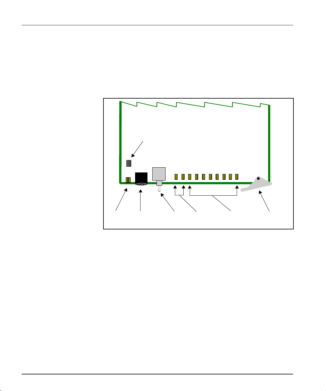
Figure 1-1 shows the position of the LEDs and module controls on the
front of the HUC6800+ and HUC6800+C modules.
Remote/local
control jumper
Module
status
LEDs
Mode select
rotary
switch
Navigation
toggle
switch
Control
LEDs
Monitoring
LEDs
Extractor
handle
Figure 1-1. Typical 6800+ Module
Table 1-1 on page 5 briefly describes generic 6800+ LEDs, switches,
and jumpers.
4 HUC6800+ Installation and Operation Manual

Table 1-1. Generic 6800+ Module Features
Feature Description
Chapter 1: Introduction
Module status
LEDs
Mode select
rotary switch
Navigation
toggle switch
Control LEDs Various lighting combinations of these Control LEDs
Monitoring
LEDs
Local/remote
control jumper
Various color and lighting combinations of these LEDs
indicate the module state. See “LEDs and Alarms” on
page 48 for more information.
This switch selects between various control and
feedback parameters.
This switch navigates up and down through the available
control parameters:
• Down: Moves down through the parameters
• Up: Moves up through the parameters
(sometimes referred to as “Bank Select LEDs”) indicate
the currently selected bank. See “Bank Select LEDs” on
page 33 for more information.
Each 6800+ module has a number of LEDs assigned to
indicate varying states/functions. See “Monitoring
LEDs” on page 48 for a description of these LEDs.
• Local: Locks out external control panels and allows
card-edge control only; limits the functionality of
remote software applications to monitoring
• Remote: Allows remote or local (card-edge)
configuration, operation, and monitoring of the
HUC6800+ and HUC6800+C
See page 12 for more information on jumpers.
HUC6800+ Installation and Operation Manual 5
Chapter 1: Introduction
Back Connectors
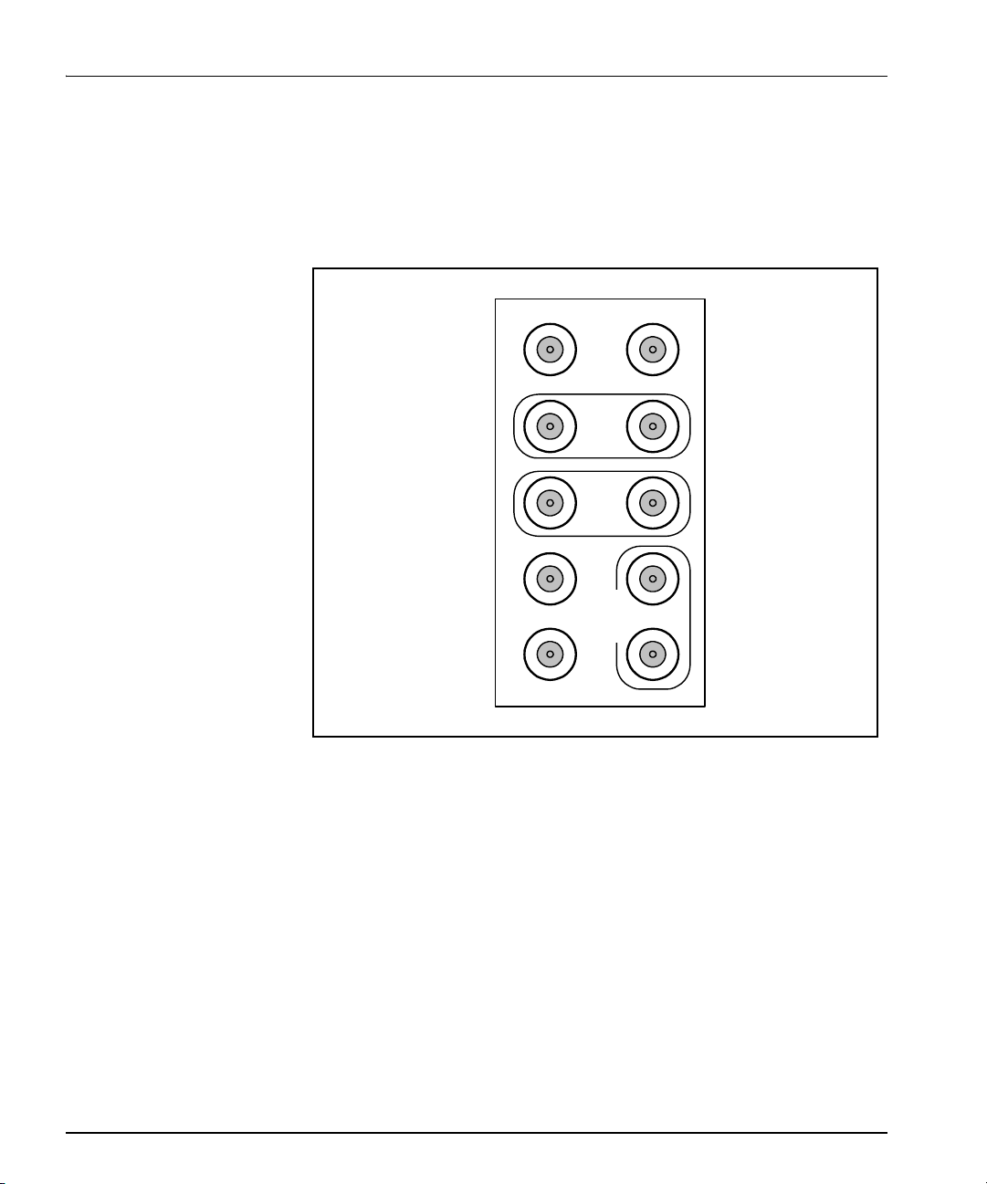
Figure 1-2 shows the double-slot back connector used by the
HUC6800+ and HUC6800+C modules. The back connectors and the
modules must be installed in an FR6802+XF frame (6800/7000 series
frames do not provide backward-compatibility).
SD/HD IN
RCLK
SD/HD
OUT
12
HD PROG
OUT
12
REF IN
Signal Flow
DATA OUT
HD
PROG/MON
OUT
1
2
Figure 1-2. HUC6800+ and HUC6800+C Back Connectors
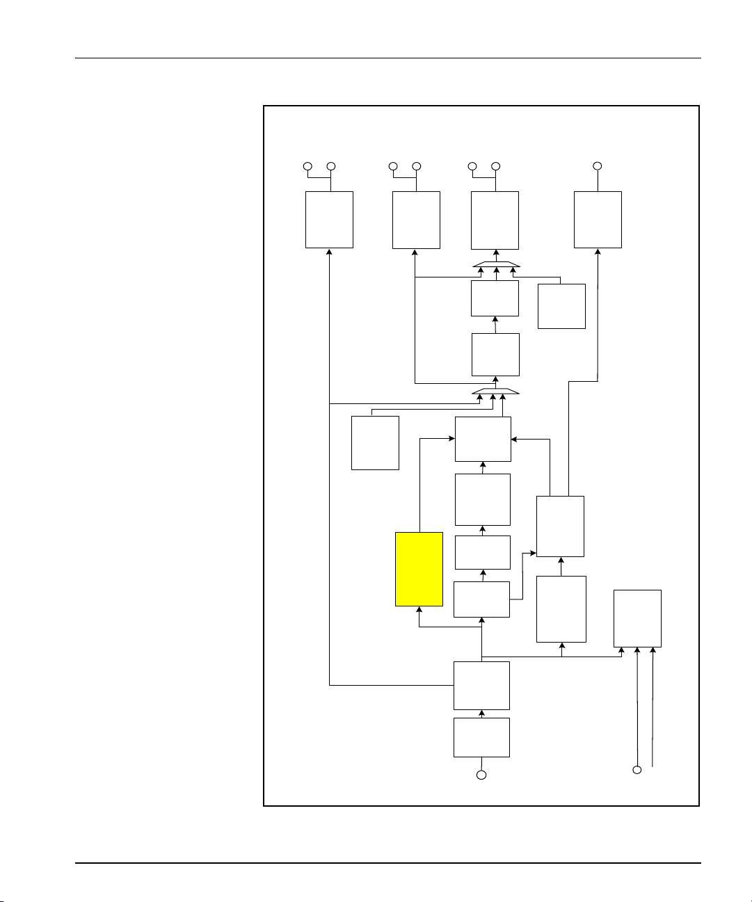
Figure 1-3 on page 7 illustrates the signal flow of the HUC6800+ and
HUC6800+C modules.
6 HUC6800+ Installation and Operation Manual
Chapter 1: Introduction
SDI
output
reclocked
output
HD-SDI
program
output
HD-SDI
monitor
IODLY
(audio)
HD-SDI
serialize r +
cable driver
HD-SDI
serializer +
cable driver
[HD]
generator
Video test
CC
708
608 payload into
HD-SDI
serializer +
cable driver
On
[HD]
screen
display
[HD]
keyer
Reticu le
[HD]
Audio/
ANC/CC
embedder
Color
space
601 to 709
conversion
2D
video
scalar
[SD]
sync
Frame
Key
Audio sync +
2 group
Driver
[HD]
signal
delay
[SD]
demux
audio/ANC
Genlock
(HD only )
[SD]
HD/SD-SDI
deserializ er
EQ
SDI
HD/SD-
SDI
SD/HD
[SD/HD]
pass mode
HD is for output in
Genlock
Frame
reference
reference
Figure 1-3. HUC6800+ and HUC6800+C Block Diagram
HUC6800+ Installation and Operation Manual 7

Chapter 1: Introduction
8 HUC6800+ Installation and Operation Manual

Overview
Caution
Before installing this product,
read the 6800+ Series Safety
Instructions and Standards
Manual shipped with every
FR6802+ Frame Installation
and Operation Manual. This
information is also available at
www.broadcast.harris.com/
leitch. The safety manual
contains important information
about the safe installation and
operation of 6800+ series
products.
Chapter 2
Installation
This chapter describes the HUC6800+ and HUC6800+C installation
process, including the following topics:
• “Maximum 6800+ Frame Power Ratings” on page 10
• “Unpacking the Module” on page 11
• “Setting Jumpers” on page 12
• “Installing HUC6800+ and HUC6800+C Modules” on page 14
• “Upgrading Module Firmware” on page 15
See the FR6802+ Frame Installation and Operation Manual for
information about installing and operating an FR6802+ frame and its
components.
HUC6800+ Installation and Operation Manual 9

Chapter 2: Installation
Maximum 6800+ Frame Power Ratings
The power consumption for the HUC6800+ and HUC6800+C modules
is less than 10.5 W.
Table 2-1 shows the maximum allowable power ratings for 6800+
frames. Note the given maximums before installing any 6800+ modules
in your frame.
HUC6800+ and HUC6800+C modules can be installed in FR6802+XF
frames only.
Table 2-1. Maximum Power Settings for Frames with AC Power
Supply
6800+ Frame
Type
FR6802+XF
(frame with fans)
Max. Frame
Power
Dissipation
120 W 10 12 W
Number
of Usable
Slots
Max Power
Dissipation for
Two Slots
Table 2-2. Maximum Power Settings for Frames with DC Power
Supply
6800+ Frame
Type
FR6802+XF
(frame with fans)
Max. Frame
Power
Dissipation
105 W 10 10.5 W
Number
of Usable
Slots
Max Power
Dissipation for
Two Slots
10 HUC6800+ Installation and Operation Manual
Unpacking the Module
Preparing the Product for Installation
Before you install the HUC6800+ and HUC6800+C, perform the
following:
• Check the equipment for any visible damage that may have
Note
Contact your customer service
representative if parts are
missing or damaged.
occurred during transit.
• Confirm receipt of all items on the packing list. See “Checking the
Packing List” below for more information.
• Remove the anti-static shipping pouch, if present, and all other
packaging material.
• Retain the original packaging materials for possible re-use.
See “Unpacking/Shipping Information” on page ix for information
about returning a product for servicing.
Chapter 2: Installation
Checking the Packing List
Table 2-3. Available Product Packages
Ordered Product Content Description
HUC6800+ or
HUC6800+C module
• One front module
• One back connector
• One HUC6800+ and HUC6800+C Broadcast
Upconverters Installation and Operation
Manual
HUC6800+ Installation and Operation Manual 11
Chapter 2: Installation
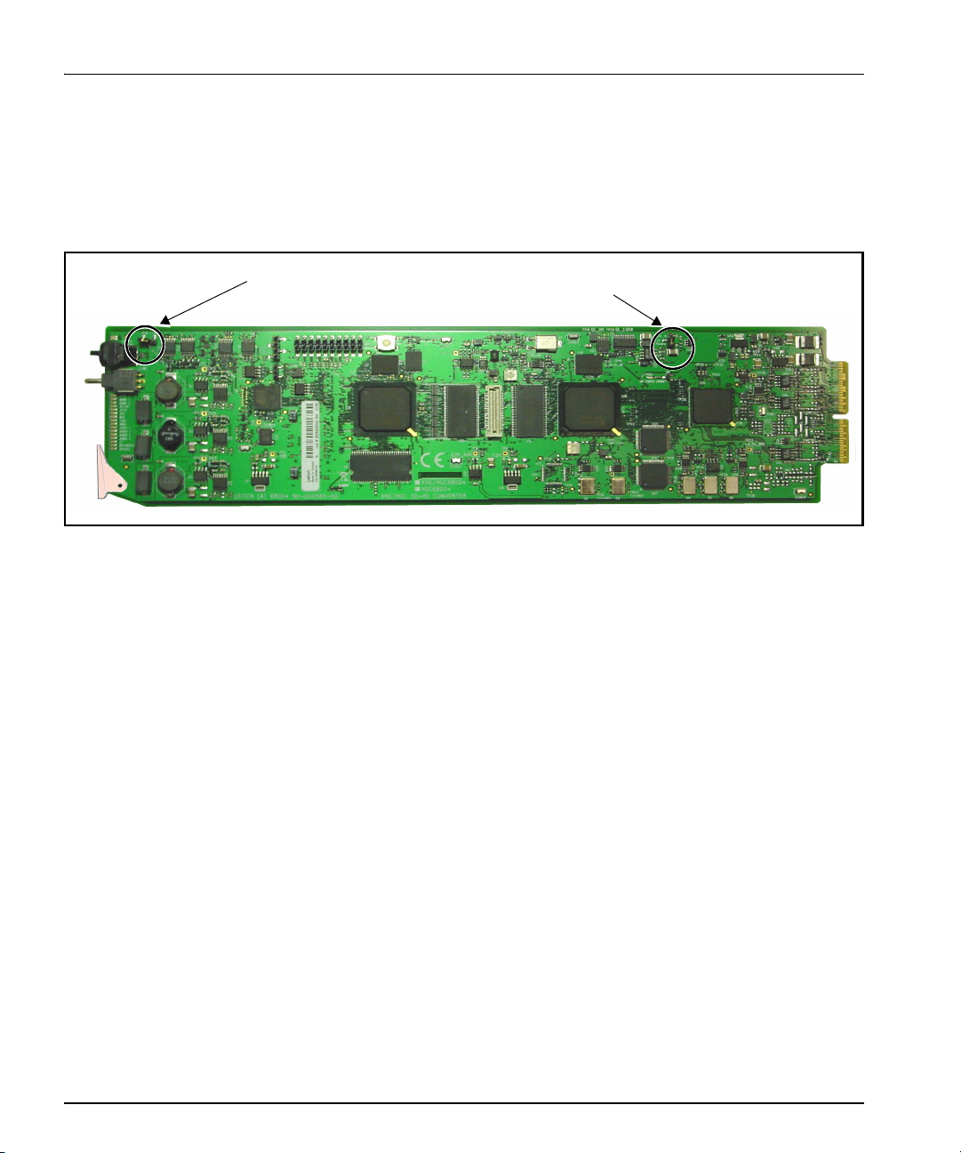
Setting Jumpers
The HUC6800+ and HUC6800+C modules have one standard jumper
(REM/LOC) for remote or local control, and one jumper (J1) for
Genlock termination. Figure 2-1 shows the location of the jumpers.
REM/LOC
(remote/local) jumper
Jumper J1
genlock termination
Figure 2-1. HUC6800+ and HUC6800+C Jumpers
12 HUC6800+ Installation and Operation Manual
 Loading...