

Imagine communications HMX6803 Plus, OP plus HMX plus, Selenio 6800 Installation And Operation Manual

Installation and Operation Manual
Selenio 6800™
HMX6803+ & OP+HMX+
8-AES Audio Multiplexer &
8-AES Audio Multiplexer with Fiber Output
Edition E
175-100062-00
Delivering the Moment

Publicaon Informaon
© 2014 Imagine Communicaons Corp. Proprietary and Condenal.
Imagine Communicaons considers this document and its contents to be proprietary and condenal.
Except for making a reasonable number of copies for your own internal use, you may not reproduce this
publicaon, or any part thereof, in any form, by any method, for any purpose, or in any language other
than English without the wrien consent of Imagine Communicaons. All others uses are illegal.
This publicaon is designed to assist in the use of the product as it exists on the date of publicaon of this
manual, and may not reect the product at the current me or an unknown me in the future. This pub
licaon does not in any way warrant descripon accuracy or guarantee the use for the product to which
it r
efers. Imagine Communicaons reserves the right, without noce to make such changes in equipment,
design, specicaons, components, or documentaon as progress may warrant to improve the perfor
mance of the product.
-
-
Trademarks
6800+™, ADC™, CCS Navigator™, Channel ONE™, ChannelView™, ClipSync™, Delay™, D Series™, D Series DSX™, Deliver the Moment™, Delivering the Moment™, FAME™, Farad™, G8™, G Scribe™, HView™,
Ic
onMaster™, IconLogo™, IconStaon™, IconKey™, InfoCaster™, InfoCaster Creator™, InfoCaster Manager™, InfoCaster Player™, InstantOnline™, Invenio®, Live Update™, mCAPTURE™, Magellan™, Magellan CCS
N
avigator™, Magellan Q SEE™, MulService SDN™, NetPlus™, NetVX™, NewsForce™, Nexio® G8™, Nexio
AMP® ChannelView™, Nexio® Channel ONE™, Nexio® ClipSync™, Nexio® Delay™, Nexio® Digital Turnaround
Processor™, Nexio® Farad™, Nexio® G Scribe™, Nexio® IconKey™, Nexio® IconLogo™, Nexio® IconMaster™,
Nexio® IconStaon™, Nexio® InfoCaster™, Nexio® InfoCaster Creator™, Nexio® InfoCaster Manager™,
Nexio® InfoCaster Player™, Nexio® InfoCaster Trac™, Nexio® InstantOnline™, Nexio® mCAPTURE™, Nexio®
NewsForce™, Nexio® NXIQ™, Nexio® Playlist™, Nexio® Remote™, Nexio®RTX Net™, Nexio® TitleMoon™,
Nexio® TitleOne™, Nexio® Velocity ESX™, Nexio® Velocity PRX™, Nexio® Velocity XNG™, Nexio® Volt™,
OPTO+™, Panacea™, Planum™, Playlist™, Predator II GRF™, Predator II GX™, Punctuate™, Remote™, RTX
Net™, QuiC™, Q SEE™, SD STAR™, Selenio™, Selenio 6800+™, SelenioNext™, Selenio X50™, Selenio X85™,
Selenio X100™, TitleMoon™, TitleOne™, Velocity ESX™, Velocity PRX™, Velocity XNG™, Versio™,
Videotek® SD STAR™, X50™, and X85™ are trademarks of Imagine Communicaons or its subsidiaries.
Altude Express®, Connectus®, Enabling PersonalizedTV®, ICE® Broadcast System, ICE Illustrate®,
ICE Q® algorithms, ICEPAC®, Imagine ICE®, Inscriber®, Inscriber® Connectus®, Invenio®, NEO®, Nexio®,
Nexio AMP®, PersonalizedTV®, RouterWorks®, Videotek®, Videotek® ASI STAR®, Videotek® GEN STAR®,
and Videotek® HD STAR® are registered trademarks of Imagine Communicaons or its subsidiaries.
Microso® and Windows® are registered trademarks of Microso Corporaon. HD BNC is a trademark of
Amphenol Corporaon. Some products are manufactured under license from Dolby Laboratories. Dolby
and the double D symbol are registered trademarks of Dolby Laboratories. DTS Neural audio products are
manufactured under license from DTS Licensing Limited. DTS and the Symbol are registered trademarks &
the DTS Logos are trademarks of DTS, Inc. © 2008 2010 DTS, Inc. All other trademarks and trade names are
the property of their respecve companies.
Contact Informaon
Imagine Communicaons has oce locaons around the world. For locaons and contact informaon see:
hp://www.imaginecommunicaons.com/contact us/
Support Contact Informaon
For support contact informaon see:
▪ Support Contacts: hp://www.imaginecommunicaons.com/services/technical support/
▪ eCustomer Portal: hp://support.imaginecommunicaons.com
© 2014 Imagine Communicaons Corp. Proprietary and Condenal

HMX6803+
8-AES Audio Multiplexer
OP+HMX+
8-AES Audio Multiplexer
With Fiber Output
Installation and Operation Manual
Edition F
April 2013


Contents
Preface........................................................................................................................vii
Manual Information ........................................ ............................. ............................. ...vii
Purpose .............................................................................. ...................................... vii
Audience ............................... ............................................. ...................................... vii
Revision History ........................................................................................................vii
Writing Conventions ....... ... .... ... ... ... .... ................................................... .................. viii
Obtaining Documents ........ .... ... ... ... .................................................... ... ... ............... viii
Unpacking/Shipping Information .............................................................................. viii
Unpacking a Product ............................................................................................... viii
Product Servicing .......................................................................................................ix
Returning a Product ...................................................................................................ix
References .....................................................................................................................ix
Safety Standards and Compliances .............................................................................xi
Restriction on Hazardous Substances (RoHS) Compliance ...........................................xi
Waste from Electrical and Electronic Equipment (WEEE) Compliance ..........................xi
Safety Terms and Symbols in this Manual .................................................................xii
iii
Chapter 1 Introduction.............................................................................................................. 1
Product Description ............................................................. ......... ....... ......... .......... ....... 1
Main Features ............................................................................................................1
Optional Features ...................................................................................................... 2
OP+HMX+ Module Types ...........................................................................................2
Hardware Options ..................................................................................................... 3
Module Descriptions .................................................... ................................................. 3
Front Module ............................................................................................................3
Back Connectors ....................................................................................................... 4
Breakout Cables .................................... ................................................ ... .... ... ..........5
RS-422/232 Cable ....................................................... .... ... ... ... .... ............................. 8
Signal Flow .................................................................................................................. 10
Chapter 2 Installation ............................................................................................................. 11
Unpacking the Module ............................................................................................... 11
Checking the Packing List ................................................................ ... ..................... 11

Contents
iv
Choosing HMX6803+ and OP+HMX+ Upgrade Options ............................................12
Selecting an External Balun ............................... .... ... ... ... ... .......................................12
Setting Jumpers ....................................... ....................................................... ............. 13
Setting Jumper CJ1 for Local or Remote Control ......................................................13
Setting Jumpers for 600Ω/Hi-Z Input Impedance Control .........................................13
Maximum 6800+ Frame Power Ratings ................................................ ...... ...... .... ......14
Installing 6800+ Modules ............................................................................................15
Required Frames and Back Connector Types ...................................................... ... ...15
Installing and Removing HMX6803+ Modules .................................... ... ... ................15
Installing OP+HMX+ Modules ...................................................................................16
Inspecting and Cleaning Fiber Optic Connections .....................................................18
Upgrading Module Firmware ..................................................................................... 20
Chapter 3 Operation..................................................................................................................21
Operating Notes .......................................................................................................... 21
Q-SEE Compliant Thumbnails ..................................................................................... 21
Activating HMX6803+ and OP+HMX+ Functions ....................................................... 21
Adding a License Key ...............................................................................................22
Audio Test Tones .....................................................................................................22
Audio Embedding Modes .........................................................................................23
Audio Embedding Errors ..........................................................................................27
Mono Channel Audio Embedding ............................................................................27
Audio V-Fade ...........................................................................................................28
Input Audio Rate ............................................................ ... .... ... ................................28
Audio Path ...............................................................................................................29
Seamless Sound Function ......................... ... ................................................ ... .... ... ...29
Test Pattern Generator .............................................................................................30
Dolby-E Automatic Header Alignment ......................................................................31
Audio Delay Ranges .................................................................................................31
External Audio Processing Delay ............................ ... ... ... ..........................................31
Maintaining Audio/Video Alignment ........................................................................32
AFD/WSS/VI Detection and Insertion ........................................................ ... ... .... ... ...32
Cross-Functional Parameter Changes ...................................................................... ...32
Out Aspect Ratio .................. ... .... ................................................ ... .... ... ... ... .............32
ADS Clean Parameter ........... ... .... ... ... ................................................. ... ... ... ... .... ......33
PCM/Non-PCM Settings ...........................................................................................33
Channel Word Length ....... ................................................ .... ... ................................34
Parameter Availability Based on Operating Mode ..................................................... 34
Changing Parameter Settings .................................................. ......................... ..........3 6
Changing Parameter Settings Using Card-Edge Controls ..........................................36
Changing Parameter Settings Using CCS Software ......... ... .... ... ... ... ..........................38
Setting HMX6803+ Remote Control Parameters .......................................................38
LEDs and Alarms ...................................... .................................................... ................ 57
Monitoring LEDs ......................................................................................................57
Module Status LEDs .................................................................................................59
Alarms .............................. ....................................................................... ................ 59

Installation and Operation Manual
HMX6803+ and OP+HMX+
Chapter 4 Specifications........................................................................................................ 63
Inputs ........................................................................................................................... 63
SDI Video Inputs ...................................................................................................... 63
AES/DARS Inputs .................................................................................................... 64
Analog Audio Input (Analog Audio Enabled Modules Only) ..................................... 65
Outputs ..................................... .......................................................... ......................... 65
SDI Video Outputs ................................................................................................... 65
Laser Output (OP+HMX+ Only) .......................... ......................... .......................... ...... 66
Optical Port (OP+HMX+ Only) .................................. ....................... ...................... ...... 67
RS-232/RS-422 ............................................................................................................. 68
Propagation Delay ...................................................................................................... 68
Power Consumption ................................................................................................... 69
Start-Up Time .............................................................................................................. 69
Operating Temperature .............................................................................................. 69
Appendix A Audio Bit Manipulation.................................................................................... 71
Overview ..................................................................................................................... 71
Manipulating Channel Status Bits (C-Bit) .................................................. ................72
Manipulating Validity and User Bits (V-Bit and U-Bit) .............. ................................ 74
Identifying Audio Characteristics
(Audio Sampling Frequency and Word Length) ........................................ ................ 75
v
Appendix B Laser Safety Guidelines.................................................................................... 77
Laser Safety ................................................................................................................. 77
Precautions for Enclosed Systems ............................................................................. 77
Precautions for Unenclosed Systems ........................................................................78
Labels ........................................................................................................................... 78
Appendix C Communication and Control Troubleshooting Tips............................. 79
Software Communication Problems .......................................................................... 79
Hardware Communication Problems ...... ............................................................. ...... 81
Index........................................................................................................................... 83

Contents
vi

Preface
Manual Information
vii
Purpose
Audience
Revision
History
This manual details the features, installation, operation, maintenance, and specifications for
the HMX6803+ and OP+HMX+ auto-sensing SD/HD-SDI 8-AES audio demultiplexers.
This manual is written for engineers, technicians, and operators responsible for installation ,
setup, maintenance, and/or operation of the HMX6803+ and OP+HMX+
HD-SDI 8-AES audio demultiplexers.
Table P-1 Revision History of Manual
Edition Date Comments
A April 2009 Initial release
B June 2009 Additional AFD feature set
C September 2010 Addition of level-B support
D January 2012 Addition of analog audio submodule and features
E Janua ry 20 13 Minor elucidation of Input Audio Level specification
F April 2013 Update signal flow diagram and add par
firmware version 1.10
auto-sensing SD/
ameters from

viii
Preface
Writing
Conventions
To enhance your understanding, the authors of this manual have adhered to the following
text conventions:
Table P-2 W
Term or
Convention
Bold Indicates dialog boxes, property sheets, fields, buttons, check boxes,
Italics Indicates E-mail addresses, t
CAPS Indicates a specific key on the keyboard,
Code Indicates variables or c
> Indicates the direction of navigation through a hierarchy of menus
hyperlink Indicates a jump to another location within the electronic document
Internet address Indicates a jump to a website or URL
riting Conventions
Description
list boxes, combo boxes, menus, submenus, windows, lists, and
selection names
the first instances of new terms and specialized words that need
emphasis
ALT, or DELETE
something you type into a field
and
windows
or else
where
he names of books or publications, and
such as ENTER, TAB, CTRL,
ommand-line entries, such as a DOS entry or
Indicates important information that helps to avoid and troubleshoot
problems
Obtaining
Documents
Product support documents can be viewed or downloaded from our website. Alternatively,
contact your Customer Service representative to request a document.
Unpacking/Shipping Information
Unpacking a
Product
This product was carefully inspected, tested, and calibrated before shipment to ensure years
of stable and trouble-free service.
1 Check
2 Con
3 Contact your de
4 Co
5 Remo
equipment for any visible damage that may have occurred during transit.
firm that you have received all items listed on the packing list.
aler if any item on the packing list is missing.
ntact the carrier if any item is damaged.
ve all packaging material from the product and its associated componen ts bef or e you
install the unit.
Keep at least one set of original packaging, in the event that you need to return a product
r servicing.
fo

Installation and Operation Manual
HMX6803+ and OP+HMX+
ix
Product
Servicing
Returning a
Product
Except for firmware upgrades, HMX6803+ and OP+HMX+ modules are not designed for
field servicing. All hardware upgrades, modifications, or repairs r equire you to return the
modules to the Customer Service center.
In the unlikely event that your product fails to operate properly, please contact Customer
Service to obtain a Return Authorization (RA) number, and then send the unit back for
servicing.
Keep at least one set of original packaging in the event that a product needs to be returned
for service. If the original package is not available, you can supply your own packaging as
long as it meets the following criteria:
The packaging must be able to withstand the product’s weight.
The product must be held rigid within the packaging.
There must be at least 2 in. (5 cm) of space between the product and the container.
The corners of the product must be protected.
Ship products back to us for servicing prepaid and, if possible, in the original packaging
material. If the product is still within the warranty period, we will return the product prepaid
after servicing.
References ANSI/SMPTE 259M-1997
10-Bit 4:2:2 Component and 4fsc NTSC Compos ite Digital Signals - Serial Digital Interface
ITU-R BT.601-5
Studio Encoding Parameters of Digital Television for Standard 4:3 and Wide-Screen 16:9
Aspect Ratios
SMPTE 292M-1999
Bit-Serial Digital Interface for High-Definition Television Systems
ITU-R BT.709-4
Parameter Values for the HDTV Standards for Production and International Programme
Exchange
SMPTE 291M-1998
Ancillary Data Packet and Space Formatting
SMPTE RP 184-1996
Specification of Jitter in Bit-Serial Digital Systems
ANSI/SMPTE 276M-1995
Transmission of AES/EBU Digital Audio Signal Over Coaxial Cable

Preface
x
AES3-2003
AES Recommended Practice for Digital Audio Engineering - Serial Transmission Format for
Two-Channel Linearly Represented Digital Audio Data
TIA/EIA-232-E 1991
Interface Between Data Terminal Equipment and Data Circuit-Terminating Equipment
Employing Serial Binary Data Interchange
EIA/TIA-422-B 1994
Electrical Characteristics of Balanced Voltage Digital Interface Circuits
EIA RS-485 1983
Standard for Electrical Characteristics of Generators and Receivers for use in Balanced
Digital Multipoint Systems
SMPTE 346-M 2000
Time Division Multiplexing Video Signals and Generic Data over High-Definition Interface
SMPTE 352-M 2002
Video Payload Identification for Digital Interfaces
SMPTE 424-M 2005 (Proposed)
3Gb/s Signal/Data Serial Interface
SMPTE 425-M 2005 (Proposed)
3Gb/s Signal/Data Serial Interface - Source Image Format Mapping
47 Code of Federal Regulations
Part 15 FCC rules—Radio Frequency Devices
EN55103-1
EMC emission requirements applies to professional audio, video, audio-visual and
entertainment lighting control apparatus
EN55103-2
EMC immunity requirements applies to professional audio, video, audio-visual and
entertainment lighting control apparatus
IEC 61754-4
Specifications for the fiber optic connector type SC/PC
IEC 61754-2
Specifications for the fiber optic connector type ST/PC terminated to a type BFOC/2,5

IEC 61754-13
Specifications for the fiber optic connector type FC/PC
Safety Standards and Compliances
See Laser Safety on page 77 to find the safety standards and compliances for this OPTO+
series product. A 6800+ ser
Installation and Operation Manual and can be downloaded from our website. Alternatively,
contact your Customer Service representative for a copy of this safety manual.
Restriction on Hazardous Substances (RoHS) Compliance
Directive 2002/95/EC—commonly known as the European Union (EU) Restriction on
Hazardous Substances (RoHS)—sets limits on the use of certain substances found in
electrical and electronic equipment. The intent of this legislation is to reduce t he amount of
hazardous chemicals that may leach out of landfill sites or otherwise contaminate the
environment during end-of-life recycling. The Directive, which took effect on July 1, 2006,
refers to the following hazardous substances:
ies safety manual is shipped with every 6800+ Frame
Installation and Operation Manual
HMX6803+ and OP+HMX+
xi
Lead (Pb)
Mercury (Hg)
Cadmium (Cd)
Hexavalent Chromium (Cr-V1)
Polybrominated Biphenyls (PBB)
Polybrominated Diphenyl Ethers (PBDE)
According to this EU Directive, all products sold
in the European Union will be fully
RoHS-compliant and “lead-free.” (See our website for more information on dates and
deadlines for compliance.) Spare parts s upplied for the repair and upgrade of equipment
sold before July 1, 2006 are exempt from the legislation.
Equipment that complies with the
EU directive will be marked with a RoHS-compliant emblem, as shown in Figure 1.
Figure P-1 RoHS Compliance Emblem
Waste from Electrical and Electronic Equipment (WEEE) Compliance
The European Union (EU) Directive 2002/96/EC on Waste from Electrical and Electronic
Equipment (WEEE) deals with the collection, treatment, recovery, and recycling of electrical
and electronic waste products. The objective of the WEEE Directive is to assign the
responsibility for the disposal of associated hazardous waste to either the producers or users
of these products. As of August 13, 2005, the producers or users of these products were
required to recycle electrical and electronic equipment at end of its useful life, and may not
dispose of the equipment in landfills or by using other unapproved methods. (Some EU
member states may have different deadlines.)
xii
Preface
In accordance with this EU Directive, companies selling electric or electronic devices in the
EU will affix labels indicating that such products must be properly r ecycled. (See our website
for more information on dates and deadlines for compliance.) Contact your local Sales
representative for information on returning these products for recycling. Equipment that
complies with the EU directive will be marked with a WEEE-compliant emblem, as shown in
Figure 2.
Figure P-2 WEEE Compliance Emblem
Safety Terms and Symbols in this Manual
This product manual uses the following safety terms and symbols to identify certain
conditions or practices. See Laser Safety
and Standards Manual fo
WARNING
Statements identifying con
personal injury or loss of life. High voltage is present.
CAUTION
Statements identifying conditions or
damage to the equipment or other property.
r more information.
ditions or practices that may result in
on page 77 and the FR6802+ Safety Instructions
practices that can result in

Introduction
1
Product Description
The HMX6803+ is an auto-sensing SD/HD-SDI 4-AES audio multiplexer and processing
amplifier with one digital video input and one DARS refer ence input, and has four pr ocessed
SD/HD-SDI outputs. The OP+HMX+ module has the same features, and an additional optical
transmitter. The modules support embedding and passing of Dolby E™ metadata, and
picture and sound control through integrated processing amplifiers. The basic HMX6803+
and OP+HMX+ provide SD and HD-SDI audio embedding, and there is an optional upgrade
to 3G HD-SDI (including dual-link). Another optional upgrade adds four AES inputs, for a
total of eight.
1
Main
Features
Each HMX6803+ or OP+HMX+ package includes a module-specific breakout cable with
unbalanced (coaxial) audio connectors that expands the numb er of available connections
beyond what would fit on a standard two-slot back connector. Balanced AES inputs are
supported with external baluns. The breakout cable includes an RS-232/RS-422 serial
connector to embed metadata.
HMX6803+ and OP+HMX+ can be operated locally (using card-edge controls); or operated
and monitored remotely with control softwar e applications such as CCS
web browser, third-party SNMP-based control applications, or CCS-co mplian t remote
control panels such as NUCLEUS. The modules are QSEE™-compliant, so you can monitor a
thumbnail when it is installed in an Ethernet-equipped FR6802+QXF or FR6822+ frame.
The HMX6803+ and OP+HMX+ back connector requires two frame slots within an
FR6802+XF, FR6822+, or FR6802+QXF frame. The HMX6803+AI+T and OP+HMX+AI+T
require three slots within the same frames. There is no backward compatibility provided for
use with 6800/7000 series frames or FR6802+DM frames. HMX6803+ and OP+HMX+ must
be installed in a frame with fans.
All versions of HMX6803+ and OP+HMX+ include the following features:
Inputs
One serial digital SMPTE 292M/SMPTE 259M SDI input
Metadata
Four AES audio
DARS input (unbalanced, balanced compatible with external balun)
Outputs
Four serial digital SMPTE 292M/259M SDI processed outputs
One RS-232/RS-422 serial connector to embed metadata
Navigator™, HTTP

2
Chapter 1
Introduction
10-bit video processing in the following standards and frame rates:
Standard definition 525/625
1080psf (progressive segmente d frame), 23.98/24 Hz
1080i (interlaced), 25/29.97/30 Hz
1080p (progressive), 23.98/24/25/29.97/30 Hz
720p (progressive), 50/59.94/60 Hz
Up to 50 frames of SD video delay, up to 11 frames of HD video delay
Auto-detect or user-forced input video standard with HD/SD-SDI auto sensing
AFD/WSS/VI detector and inserter
Seamless sound functionality
V-fading of the output audio on source audio change
Automatic cable equalization
Embed on black or grey on loss of video mode
Video processing amplifier with luminance gain/offset and chrominance gain/offset
controls
16-, 20-, or 24-bit audio proces sing
Shadowed/restored parameter settings when switching video standards
Card-edge control and monitori ng
Serial and Ethernet remote control and monitoring
Video and audio test signal generators
Optional Features
OP+HMX+
Module
Types
OP+HMX+ has an optional fiber transmitter.
HMX68OPT+AES8
The HMX68OPT+3G upg
adds four balanced or unbalanced AES inputs, for a total of eight.
rade option adds 10-bit video processing wit h 1080p (pr ogr essive)
video standard at 50/59.94/60 Hz frame rates as per SMPTE 424M and dual-link as per
SMPTE 372M (data and audio embed/de-embed is fixed on link A).
HMX6803+AI+T and OP+HM
X+AI+T add analog audio inputs.
Table 1-1 describes the different versions of the OP+HMX+ product. The basic module
outputs through an SC/PC connector. Hardware upgrade options are listed in Table 1-2.
Table 1-1 OP+HMX+ Modules
Module Name Description
OP+HMX+13
D Fiber transmitter set at 1310 nm
OP+HMX+CxxD Fiber transmitter set at CWDM
w
avelength of 1xx0 nm
OP+HMX+AI+13
T Fiber transmitter set at 1310 nm with
analog audio inputs
OP+HMX+AI+CxxT Fiber transmitter set at CWDM
w
avelength of 1xx0 nm with analog
audio inputs
Installation and Operation Manual
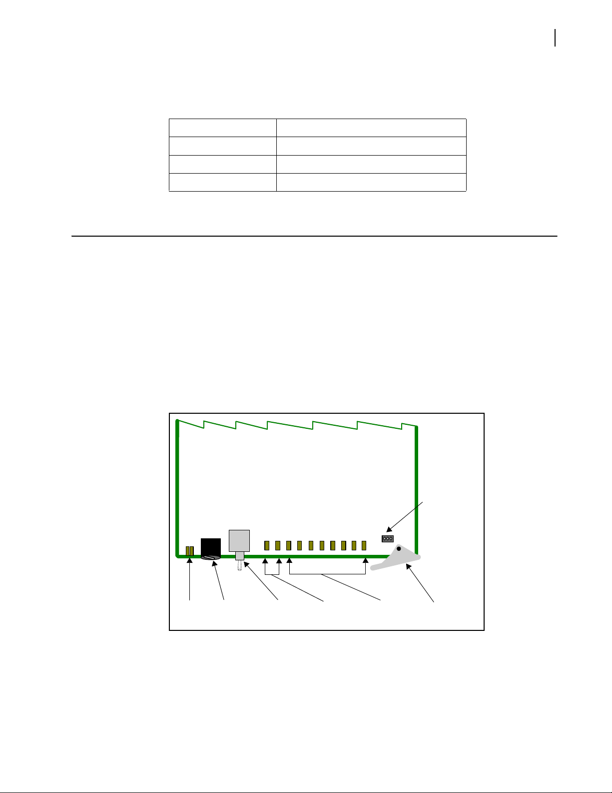
Modul
e
status
Mode select
rotary
Navigation
toggle
Monitoring
LEDs
Remote/local
control
Extractor
handle
Control
LEDs
HMX6803+ and OP+HMX+
3
Hardware
Options
All OP+HMX+ modules are shipped with standard SC/PC fiber connectors. Other
connectors are available (see Table 1-2).
Table 1-2 A
Item Description
+OPT+SC SC/PC fiber optic connectors (standard)
OP
OP+OPT+ST ST/PC fiber optic connectors (optional)
OP+OPT+FC FC/PC fiber optic connectors (optional)
Module Descriptions
HMX6803+ and OP+HMX+ hardware versions have minor variances in their specifications,
which are listed in Chapter 4, Spe
To determine which specifications app
Hardware Versions o
Front Module
Figure 1-1 is a generic top-front view of a typical 6800+ module and shows the general
location of standard LEDs, controls, and jumpers. The number of control and monitoring
LEDs on
6800+ modules varies.
vailable Connectors
cifications on page 63.
ly to your module, see Reading Software and
n page 37.
Figure 1-1 Typical 6800+ Module
Table 1-3 o
n page 4 briefly describes generic 6800+ LEDs, switches, and jumpers. See
Chapter 3, Ope
ration for more information on specific HMX6803+ and OP+HMX+
module controls, LEDs, and jumpers.

4
Chapter 1
Introduction
Table 1-3 Generic 6800+ Module Features
Feature Description
Module status
LEDs
Various color and lighting combinations of these LEDs indicate
e module state. See Monitoring LEDs on
th
page 57 for more
information.
Mode select
ro
tary switch
Navigation
toggle switch
This switch selects between various control and feedback
parameters.
This switch navigates up and down through the available
con
trol parameters:
Down: Moves down through the par ameters
Up: Moves up through the parameters
Control LEDs Various lighting combinations of these control LE
(sometimes referred to as “Bank Select LEDs”) indicate which
bank is currently selected. See Selected Bank as Indicated
on page 36 for more information.
ule has a number of LEDs assigned to
Monitoring
LEDs
by Control LEDs
Each 6800+ mod
indicate varying states/functions. See Monitoring LEDs on
page 57 for a description of these LEDs.
Local/remote
control jumper
Local: This jumper setting locks out external control panels
and allows card-edge control only; limits the functionality
of remote software applications to monitoring
Remote: This jumper setting allows remote or local
(card-edge) configuration, operatio n, and monitoring of
the HMX6803+ and OP+HMX+ (this is the default setting)
Ds
Back
Connectors
Figure 1-2 shows the double-slot back connector used by HMX6803+ and OP+HMX+
modules.
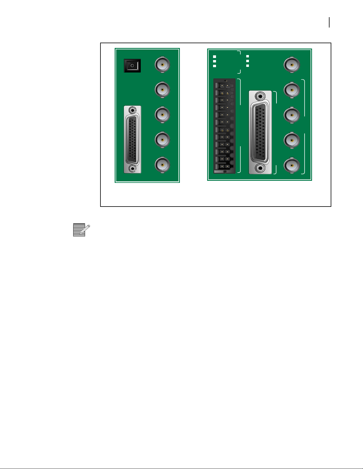
SDI IN 1
SDI OUT 1
SDI OUT 2
SDI OUT 3
SDI OUT 4
BREAKOUT
Fiber
AES IN / AES OUT / DARS / METADATA
HMX6803+
HDX6803+
SFS 6803+
OP+HMX+
OP+HDX+
OP+SFS+
SDI IN
SDI OUT
1
2
3
4
ANALOG AUDIO IN / OUT
Rx/Tx (OP+)
Two-slot back connector for
HMX6803+ and OP+HMX+
Three-slot back connector for
HMX6803+AO+T and
OP+HMX+AO+T
Installation and Operation Manual
HMX6803+ and OP+HMX+
5
Breakout
Cables
Figure 1-2 HMX6803+ and OP+HMX+ Back Connector
To maintain optimal output video signal integrity, terminate unused output video
Note:
Ω
BNCs with 75
terminators.
The standard HMX6803+ and OP+HMX+ ship with an unbalanced breakout cable, pictured
in Figure 1-3. For information on ordering cables, see Table 2-1 o
n page 11.
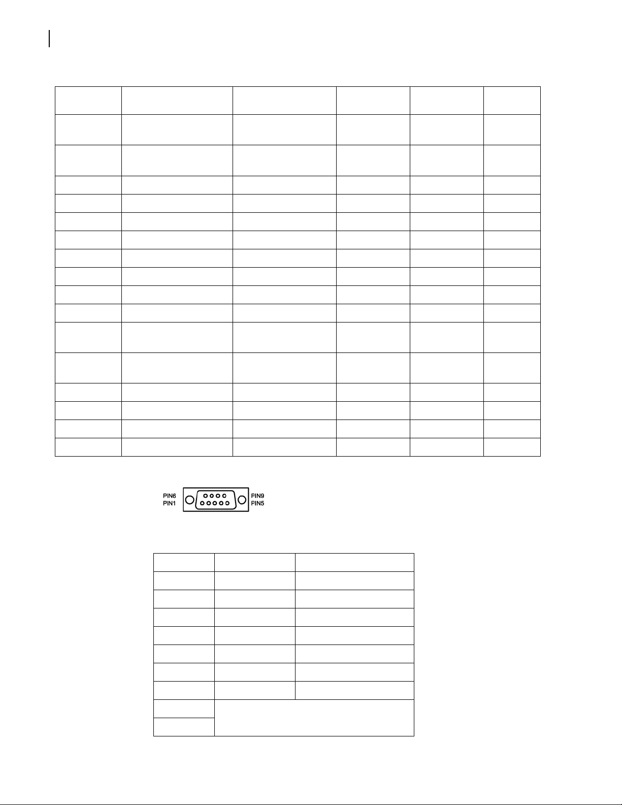
If you need to make your own breakout cable, pinouts are listed in Table 1-4, and pin
numbers for the 44-pin connector are listed in Figure 1-4 o
n page 7.
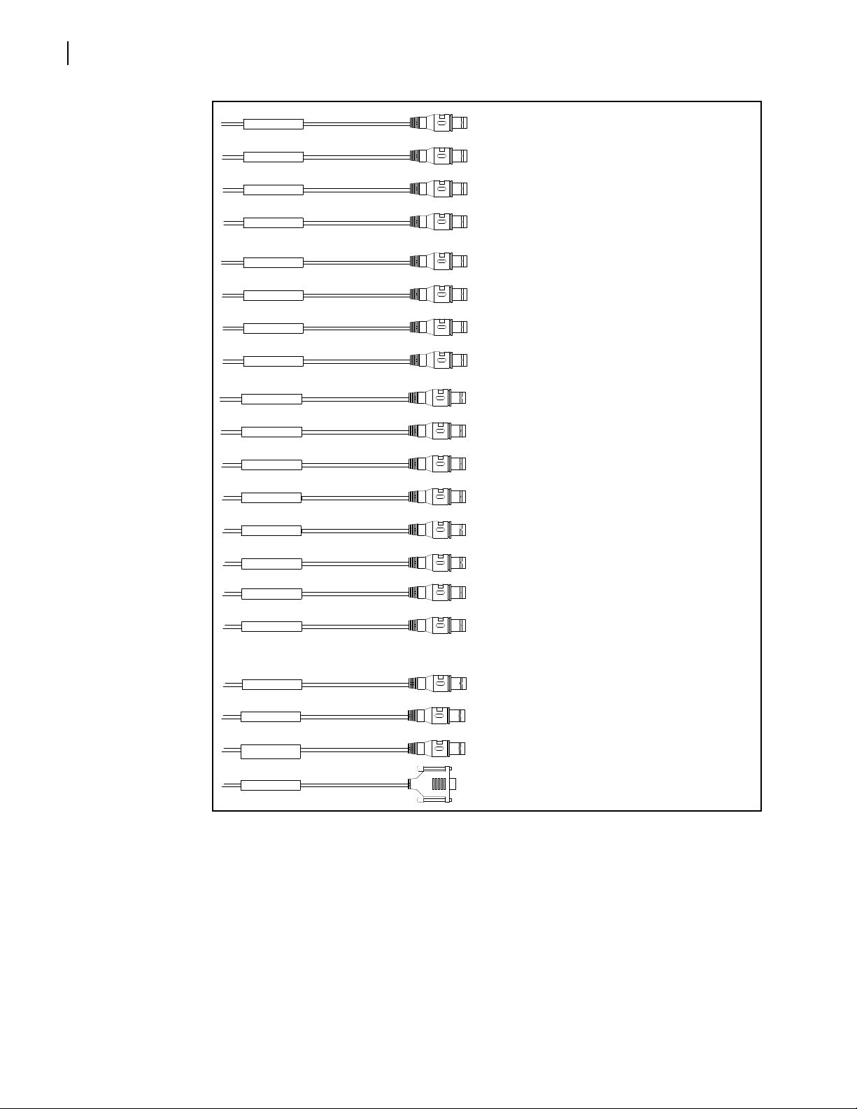
AES 1 I n
AES 2 I n
AES 3 I n
AES 4 I n
AES 5 I n
AES 6 I n
AES 7 I n
AES 8 I n
AES 1 O ut
AES 2 O ut
AES 3 O ut
AES 4 O ut
AES 5 O ut
AES 6 O ut
AES 7 O ut
AES 8 O ut
DARS In
Data I/O
Genlock
Serial
AES1 IN
AES2 IN
AES3 IN
AES4 IN
AES5 IN
AES6 IN
AES7 IN
AES8 IN
AES1 OUT
DARS IN
DATA I/O
GENLOCK
SERIAL
AES2 OUT
AES3 OUT
AES4 OUT
AES5 OUT
AES6 OUT
AES7 OUT
AES8 OUT
(not used with HMX6803+ and OP+HMX+)
6
Chapter 1
Introduction
Figure 1-3 HMX6803+ and OP+HMX+ Breakout Cable

Figure 1-4 Pin Numbers for 44-Pin Connector
Table 1-4 Pinouts for 44-Pin Connector
Installation and Operation Manual
HMX6803+ and OP+HMX+
7
Pin No. on
4M
DB-4
Connection Type Description Wire Label
External
Cable Color
BNC
Color
1 BNC GENLOCK GENLOCK Black Black
2 BNC GND GENLOCK GND GENLOCK Black Black
3 BNC GND AES OUT 7 GND AES OUT 7 Blue Blue
4 BNC AES IN 4 AES IN 4 White White
5 BNC GND AES IN 4 GND AES IN 4 White White
6 BNC AES IN 3 AES IN 3 White White
7 BNC GND AES IN 3 GND AES IN 3 White White
8 BNC DATA IO DATA IO Yellow Yellow
9 BNC GND DATA IO GND DATA IO Yellow Yellow
10 BNC AES OUT 2 AES OUT 2 Blue Blue
11 BNC GND AES OUT 2 GND AES OUT 2 Blue Blue
12 BNC AES OUT 1 AES OUT 1 Blue Blue
13 BNC GND AES OUT 1 GND AES OUT 1 Blue Blue
14 BNC GND AES IN 7 GND AES IN 7 White White
15 BNC AES IN 7 AES IN 7 White White
16 Not Connected
17
18 BNC AES OUT 7 AES OUT 7 Blue Blue
19 BNC DARS IN 1 DARS IN 1 Yellow Black
20 BNC GND DARS IN 1 GND DARS IN 1 Yellow Black
21 BNC AES IN 2 AES IN 2 White White
22 BNC GND AES OUT 3 GND AES OUT 3 Blue Blue
23 BNC AES OUT 3 AES OUT 3
Blue Blue
24 BNC GND AES OUT 6 GND AES OUT 6 Blue Blue
25 162A10019X (DB9.5) RS232_GND (DB9) SERIAL Black N/A
25 BNC GND AES OUT 4 GND AES OUT 4 Blue Blue
26 BNC AES OUT 4 AES OUT 4 Blue Blue
27 BNC GND AES OUT 5 GND AES OUT 5 Blue Blue
28 BNC AES IN 8 AES IN 8 White White
29 BNC GND AES IN 8 GND AES IN 8 White White
30 BNC GND AES IN 5 GND AES IN 5 White White
8
Chapter 1
Introduction
Table 1-4 Pin
Pin No. on
DB-44M
31 162A10019X (DB9.3) BALANCED SERIAL IN-
32 162A10019X (DB9.8) BALANCED SERIAL
33 BNC GND AES OUT 8 GND AES OUT 8 Blue Blue
34 BNC AES OUT 8 AES OUT 8 Blue Blue
35 162A10019X (DB9.1) RS422_FR_GND (DB9) SERIAL Black N/A
35 BNC GND AES IN 2 GND AES IN 2 White White
36 BNC AES IN 1 AES IN 1 White White
37 162A10019X (DB9.9) RS422_FR_GND (DB9) SERIAL Black N/A
37 BNC GND AES IN 1 GND AES IN 1 White White
38 BNC AES OUT 6 AES OUT 6 Blue Blue
39 162A10019X (DB9.7) BALANCED SERIAL
40 162A10019X (DB9.2) BALANCED SERIAL
outs for 44-Pin Connector (Continued)
Connection Type Description Wire Label
SERIAL Red N/A
(
DB9)
SERIAL Yellow N/A
IN+ (DB9)
SERIAL Blue N/A
OUT
- (DB9)
SERIAL Green N/A
OUT
+ (DB9)
External
Cable Color
BNC
Color
41 BNC AES OUT 5 AES OUT 5 Blue Blue
42 BNC GND AES IN 6 GND AES IN 6 White White
43 BNC AES IN 6 AES IN 6 White White
44 BNC AES IN 5 AES IN 5 White White
RS-422/232
Cable
Figure 1-5 Pin Numbers for RS-422/232 Female Connector
Table 1-5 Pin Assign
Pin No. Signal Comments
1 FG Frame Ground
9 FG Frame Ground
5 FG Frame Ground
2 TA (Tx-) Transmitted Data 7 TB (Tx+) Transmitted Data +
8 RA (Rx-) Received Data -
ment of DB-9 Connector (Female) in RS-422 Format
3 RB (Rx+) Received Data +
4 Not connected
6
Installation and Operation Manual
Pin 1
HMX6803+ and OP+HMX+
Table 1-6 Pin Assignment of DB-9 Connector (Female) in RS-232 Format
Pin No. Signal Comments
1 FG Frame Ground
9 FG Frame Ground
5 FG Frame Ground
2 Tx Transmitted Data
7 Not connected
8
3 Rx Received Data
4 Not connected
6
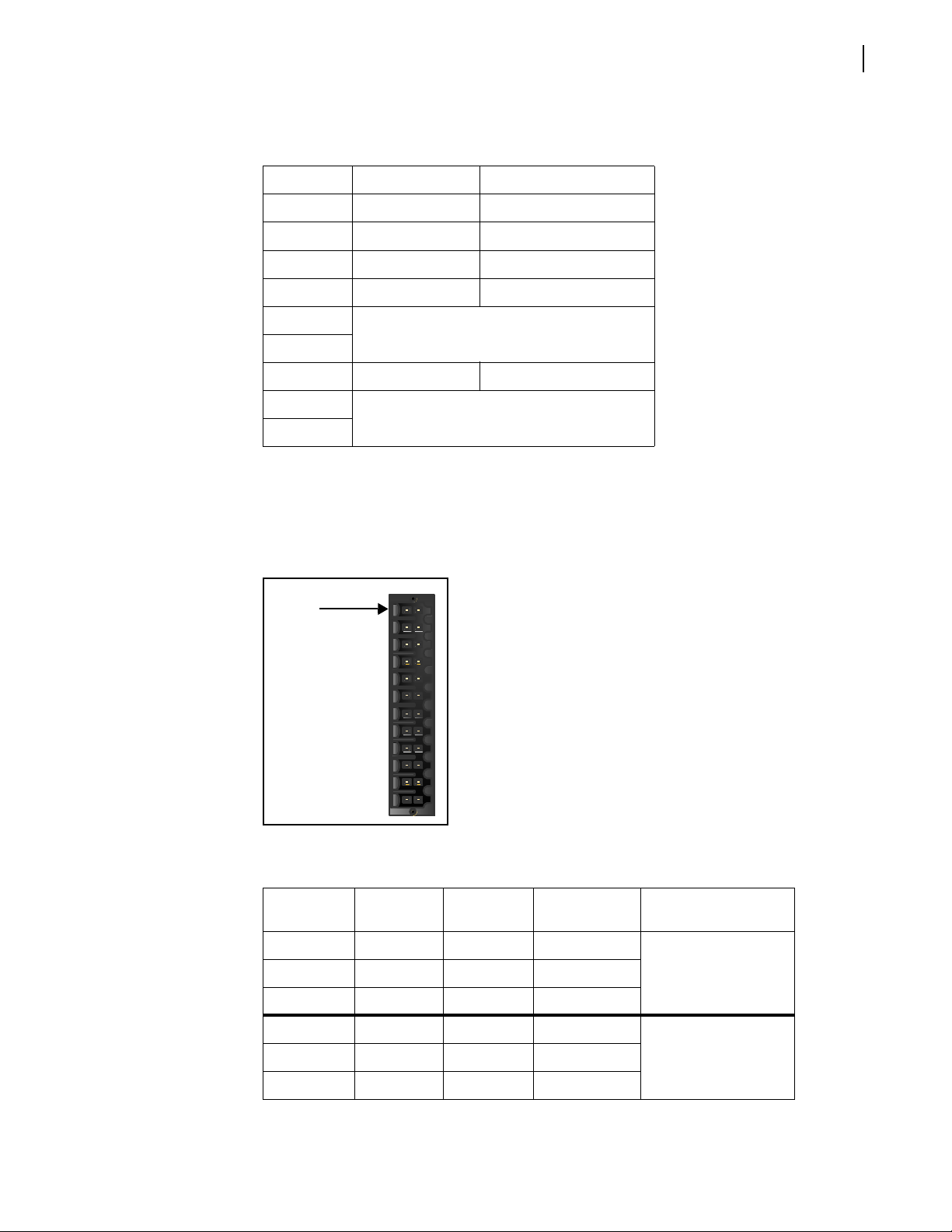
Weidmuller Connector for Analog Audio Inputs
9
The HMX6803+AI+T and OP+HMX+AI+T back modules have an additional connector. It
has has the following connections:
Figure 1-6 Analog Audio Connector Pinouts
Table 1-7 Analo
Pin
Number
g Audio Pinouts
Signal
Pin
Number
Signal Comments
1 CH1A+ 13 CH1A-
Input 1 2 CH1B+ 14 CH1B3 GND 15 GND
4 CH2A+ 16 CH2A-
Input 2 5 CH2B+ 17 CH2B6 GND 18 GND
10
1
Available via breakout cable (included) .
3G/HD/SD-SDI
Metadata
Video
Delay
Test
pattern
generator
Sample
rate
converter
Audio
delay
Metadata
router
CCS & QSEE
monito ring
&
control
Laser
Driver
Audio
proc amp
OP+SFS+( C)xxD
Equalizer
3G/HD/SD-SDI
2
3G/HD/SD-SDI
2
Driver
Driver
CCS & SNMP
control
DARS DARS
AFD/WSS/VI
Detector
AES In
8
Stereo analog
audio in
HMX6803+AI+T
4
A
B
Audio Embed
Metadata Embed
Video Proc
VBI Delete
AFD/WSS/VI embed
Serializer
Chapter 1
Introduction
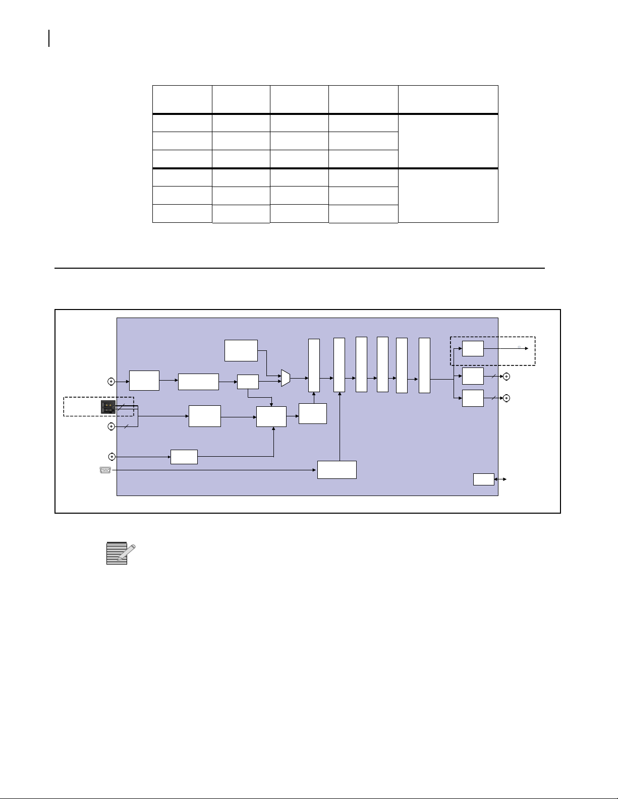
Signal Flow
Table 1-7 Analog
Pin
Number
Audio Pinouts (Continued)
Signal
Pin
Number
Signal Comments
7 CH3A+ 19 CH3A-
9 GND 21 GND
10 CH4A+ 22 CH4A-
12 GND 24 GND
Input 38 CH3B+ 20 CH3B-
Input 411 CH4B+ 23 CH4B-
Figure 1-7 HMX6803+ and OP+HMX+ Signal Flow Diagram
3G HD-SDI in and out are only available if your module has the optional
Note:
HMX68OPT
+3G license key.

2
11
Installation
Unpacking the Module
Checking the
Packing List
Before you install modules, perform the following:
Check the equipment for any visible damage that may have occurred during transit. Confirm receipt of all items on the packing list. See Checking the Packing List for
more information.
Contact your Customer Service representative if parts are missing or damaged.
Note:
Remove the anti-static shipping pouch, if present, and all other packaging material.
Retain the original packaging materials for possible re-use.
See Unpacking/Shipping Information o
product for servicing.
Table 2-1 Available Product Packages
Ordered Product Conten t Description
HMX6803+D
OP+HMX+D
One HMX6803+ front module
One double-slot back connector
One 6800+OPT+16CAPM breakout cable with unbalanced
audio connectors
One HMX6803+ and OP+HMX+ Installation and Operation
Manual
One OP+HMX+ front module
One double-slot back connector
One 6800+OPT+16CAPM breakout cable with unbalanced
audio connectors
One HMX6803+ and OP+HMX+ Installation and Operation
Manual
n page viii for information about returning a

12
Chapter 2
Installation
Table 2-1 A
vailable Product Packages (Continued)
Ordered Product Content Description
HMX6803+AI+T
One HMX6803+ front module with submodule providing eight
mono or four stereo analog audio inputs
One triple-slot back connector
One 6800+OPT+16CAPM br eakout cable with unbalanced
audio connectors
One HMX6803+ and OP+HMX+ Installation and Operation
Manual
OP+HDX+AI+T
One OP+HMX+ front mo dule w ith s ubmodule p r o viding ei ght
mono or four stereo analog audio inputs
One triple-slot back connector
One 6800+OPT+16CAPM br eakout cable with unbalanced
audio connectors
One HMX6803+ and OP+HMX+ Installation and Operation
Manual
6800+OP
T+16CAPM One breakout cable with unbalanced au dio connectors
Choosing HMX6803+ and OP+HMX+ Upgrade Options
Basic HMX6803+ and OP+HMX+ modules have one SD-SDI input and four SD-SDI outp ut s
with embedded audio. The following firmware upgrades are available:
Selecting an
External
Balun
Table 2-2 A
vailable License Key Upgrades
Ordered Product Content Description
HMX68OPT-AES8 Adds four discrete AES inputs, for a total of eight
HMX68OPT-3G Adds 3G HD-SDI and Level B functionality to an 1.5G HD-SDI
and SD-S
DI module
To purchase additional license keys, contact your Sales representative. To activate a license
ke
y, see Adding a License Key on
page 22.
The following baluns from Neutrik® or equivalent ar e recommended for the unbalanced to
balanced AES conversion:
NADITBNC-F: Female chassis XLR 110Ω input - female BNC 75Ω output.
http://www.neutrik.com/fl/en/audio/210_309314683/NADITBNC-F_detail.aspx
NADITBNC-M: Female BNC 75Ω input - male chassis XLR 110Ω output.
http://www.neutrik.com/fl/en/audio/210_2044239418/NADITBNC-M_detail.aspx
NADITBNC-FX: Female cable end XLR 110Ω input - female BNC 75Ω output.
http://www.neutrik.com/fl/en/audio/210_1576769505/NADITBNC-FX_detail.aspx
NADITBNC-MX: Female BNC 75Ω input - male cable end XLR 110Ω output.
http://www.neutrik.com/fl/en/audio/210_1923043515/NADITBNC-MX_detail.aspx
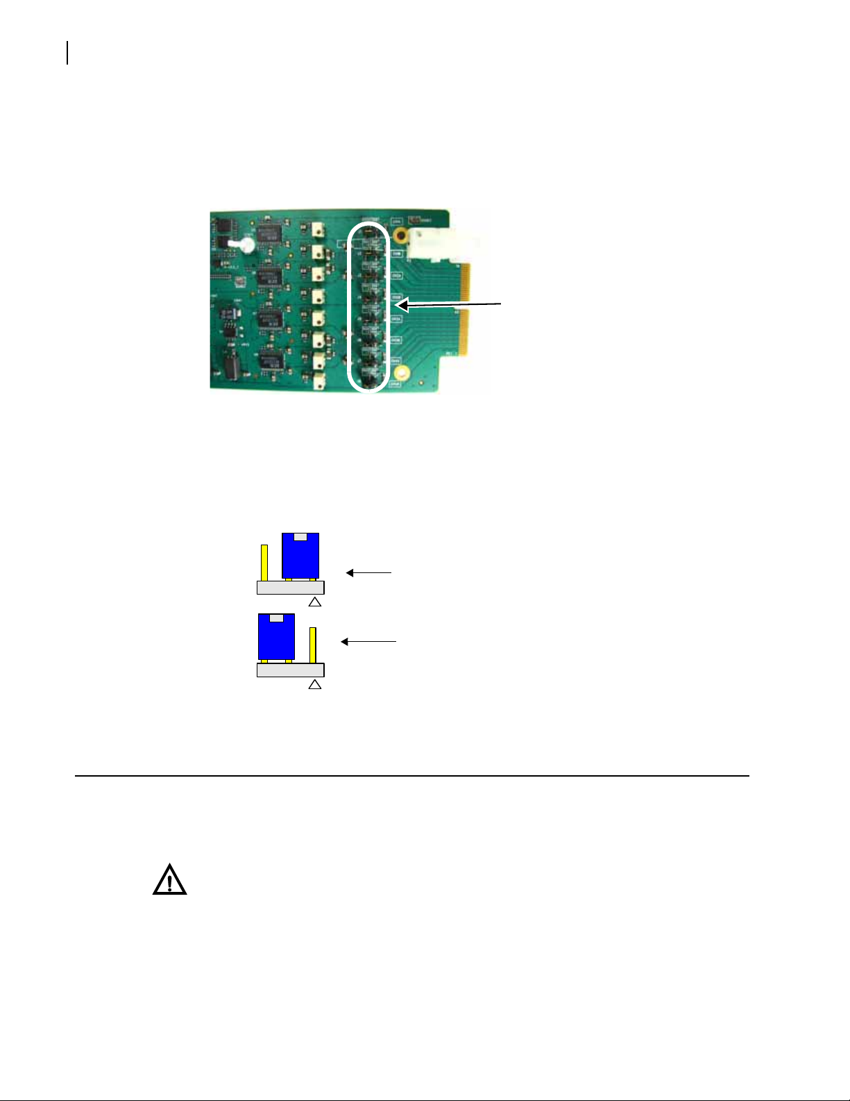
Setting Jumpers
Remote control
setting
Local control
setting
3 2 1 3 2 1
HMX6803+ and OP+HMX+ modules have one jumper, CJ1, which sets the module for local
or remote control. See Setting Jumper CJ1 for Local or Remote Control o
Installation and Operation Manual
HMX6803+ and OP+HMX+
n page 13.
13
The submodule on HMX6803+AI+T,
has eight impedance jumpers that can be set for High-Z or 660Ω impedance. See Setting
Ω
Jumpers for 600
/Hi-Z Input Impedance Control on page 13.
OP+HMX+AI+13T, and OP+HMX+AI+CxxT modules
Setting Jumper CJ1 for Local or Remote Control
The HMX6803+ and OP+HMX+ module has one jumper, CJ1, which sets the module for
local or remote control.
Note: You need to configure modules for local or remote operation prior to power-up. To
change the configuration, first remove power from the module, reset the jumper, and then
eapply power.
r
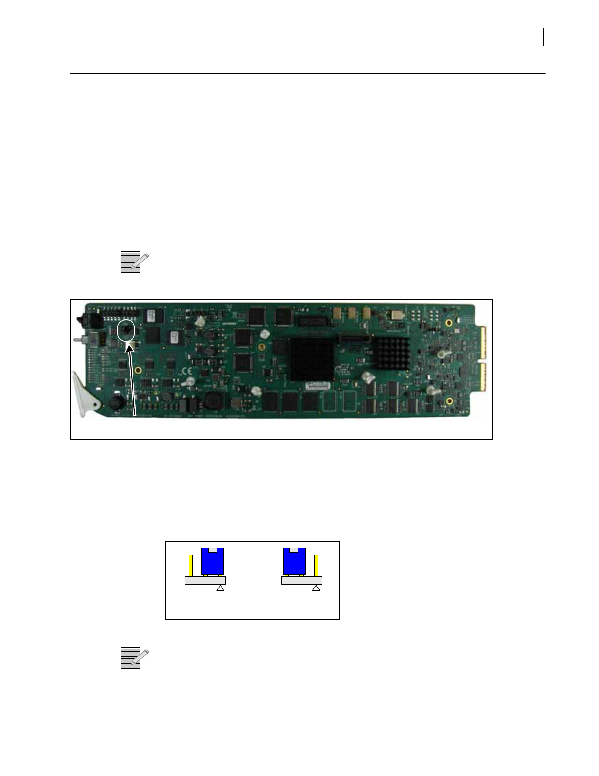
Figure 2-1 Jumper Location
1 Locate jumper CJ
Figure 2-1 shows the location of the CJ1 jumper
2 Place
a jumper on pins 1 and 2 to set the module for Remote control, or pins 2 and 3 to set
the module for Local control. See Figure 2-2.
Figure 2-2 CJ1 Settings for Local and Remote Control
The white triangle near the jumper pins on the module
Note:
indicates pin 1.
1 on the module (behind the mode select rotary switch).
.
Setting Jumpers for 600Ω/Hi-Z Input Impedance Control
This procedure only applies to the HMX6803+AI+T, OP+HMX+AI+13T, and
OP+HMX+AI+CxxT analog audio submodule.
14
Impedance jumpers
CH1A-CH 4B
3 2 1
Ch1B
3 2 1
Ch2A
Channel 1B set for 600Ω
input
Channel 2A set for Hi-Z
input
Chapter 2
Installation
Follow this procedure to select an analog impedance of 600Ω or Hi-Z on each channel:
1 Loc
ate jumpers CH1A, CH1B, CH2A, CH2B, CH3A, CH3B, CH4A, and CH4B on the analog
audio module.
Figure 2-3 shows the location of these jumpers.
Figure 2-3 Impedance Jumpers on Analog Audio Submodule
2 Plac
e a jumper on pins 1 and 2 to set the module for 600Ω input, or pins 2 and 3 to set the
module for Hi-Z analog impedance input, as in Figure 2-2.
Do this for all eight channel jumpers.
Figure 2-4 Jumper Settings for 600W or Hi-Z Inputs
Maximum 6800+ Frame Power Ratings
See the FR6802+ Frame Installation and Operation Manual for information about installing
and operating an FR6822+, FR6802+QXF or FR6802+ frame and its components.
CAUTION:
and Standards Manual shipped
Manual or downloadable from our website . This safety manua l contains important
information about the safe installation and operation of 6800+ series products.
The power consumption for the HMX6803+ and
describes the maximum allowable po
maximums before installing any 6800+ modules in your frame.
Before installing this product, read the 6800+ Series Safety Instructions
with every 6800+ Frame Installation and Operation
OP+HMX+ modules is 12 W. Table 2-3
wer ratings for 6800+ frames. Note the given

HMX6803+ and OP+HMX+ modules operate only in fan-cooled FR6802+ and FR6822+
frames, subject to the limitations shown in Table 2-3. These modules cannot be installed in
6800/7000 series frames.
To maintain proper temperatures, ensure that the front panel is closed at all times
Note:
and that the fan module is ful
Table 2-3 Maximum Power Ratings for 6800+ Frames
ly operational.
Installation and Operation Manual
HMX6803+ and OP+HMX+
15
Max. Frame
6800+ Frame Type
FR6802+XF
(frame with AC power supply)
FR6802+XF48
(frame with DC power supply)
FR6802+Q
(with AC or DC power supply)
FR6822+ frame (
XF frame
with AC or DC power supply) 120W 20 6 W
Power
Diss
120 W 20 6 W
105 W 20 5.25 W
120W 20 6 W
Installing 6800+ Modules
Required Frames and Back Connector Types
HMX6803+ and OP+HMX+ modules have double-width back connectors that can be
installed in an FR6802+XF, FR6822+, or FR6802+QXF frame. HMX6803+ and OP+HMX+
modules cannot be installed in an FR6802+DM frame, a FR6800/7000 frame, or a frame
without fans.
ipation
Number of
Usable
Slots
Max. Power
Dissipation
Per Slot
See your 68
connectors in an FR6802+ or FR6822+ frame.
A FR6802+RM (
recommended for the HMX6803+ and OP+HMX+ modules. See your 6800+ Frame
Installation and Operation Manual for installation instructions.
00+ Frame Installation and Operation Manual for details on installing back
Rear Support Extension Rails for 6800+ series frames) option is
Installing and Removing HMX6803+ Modules
These modules require no specialized installation or removal procedures. However, if
installing both front and rear modules, ensure that the back module is installed first before
plugging in the front module.
When removing both the front and rear modules, ensure that the front module is
plugged from the frame first, before removing the rear module.
un
See the 6800+ Frame Installation and Operation Manual for information about
installing and operating a frame and its components.
16
Remove these
protective covers
Remove this
protective cover
Chapter 2
Installation
See the 6800+ Safety Instructions and Standards Manual for important information
about safely installing your module.
Once you have installed your HMX6803+ an
to the appropriate input and outputs.
d OP+HMX+ modules, you can connect them
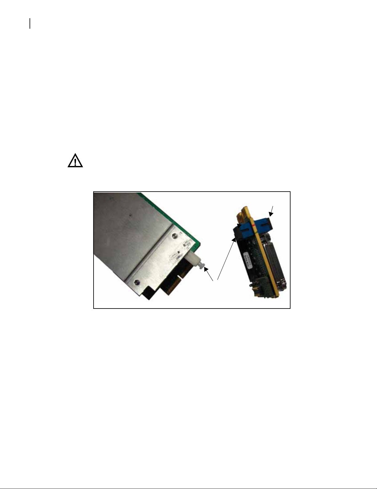
Installing
OP+HMX+
Modules
Front and back modules in the OPTO+ series have plastic caps that protect the fragile laser
connections from damage. You must remove these protective covers before you install the
back and front modules (see Figure 2-5).
In addition, all fiber optic connections must be inspected and cleaned before they are
assembl
Additional safety information appears in Laser Safety Guidelines
CAUTION
and back modules before installation. Take care to avoid touching the fiber optic
con
from the frame before installing or removing back modules.
ed. Carefully follow the inspection and cleaning steps described in the next pages.
on page 77.
: Ensure that you remove the fiber optic protective covers from the front
nections. Thoroughly clean the connections before installation. Remove power
Figure 2-5 Protective Covers for Laser Connectors
Back Module Installation
Follow these steps to install the back module into an FR6802+XF, FR6802+XF 48, FR682 2+,
or FR6802+QXF frame:
1 Remove
Do not discard the blank back plates. They may be need
a blank back plate from the frame.
ed for future configurations.
 Loading...