

Imagine communications Nexio AMP Gen-7 Series, Nexio AMP Gen-7 HDI, Nexio AMP Gen-7 HDX, Nexio AMP Gen-7 Share Hardware Manual
Delivering the MomentDelivering the Moment
Hardware Guide
Nexio® AMP Gen-7
July 2014
175-100486-01

Nexio AMP® Gen-7
Publication Information
© 2014 Imagine Communications.
Proprietary and Confidential.
Imagine Communications considers this document and its contents to be proprietary and confidential.
Except for making a reasonable number of copies for your own internal use, you may not reproduce this
publication, or any part thereof, in any form, by any method, for any purpose, or in any language other
than English without the written consent of Imagine Communications. All others uses are illegal.
This publication is designed to assist in the use of the product as it exists on the date of publication of
this manual, and may not reflect the product at the current time or an unknown time in the future. This
publication does not in any way warrant description accuracy or guarantee the use for the product to
which it refers. Imagine Communications reserves the right, without notice to make such changes in
equipment, design, specifications, components, or documentation as progress may warrant to improve
the performance of the product.
Trademarks
Product names and other appropriate trademarks, e.g. D-Series™, Nexio ®, Invenio®, PowerSmart®,
Versio™ are trademarks or trade names of Imagine Communications or its subsidiaries.
Microsoft® and Windows® are registered trademarks of Microsoft Corporation. All other trademarks and
trade names are the property of their respective companies.
Contact Information
Imagine Communications has office locations around the world. For domestic and international location
and contact information, visit our Contact page
(http://www.imaginecommunications.com/company/contact-us.aspx).
Support Contact Information
For domestic and international support contact information see:
Support Contacts http://www.imaginecommunications.com/services/technical-support.aspx
eCustomer Portal http://support.imaginecommunications.com
Academy Training http://www.imaginecommunicationsacademy.com
ICC Files Anywhere https://files.imaginecommunications.com/get
2014 Imagine Communications | All Rights Reserved Page 2 of 42

Nexio AMP® Gen-7 Contents
Contents
Overview................................................................................................................ 5
Software ................................................................................................................................................... 5
Chassis Components ................................................................................................................................. 5
Connectors and Ports ............................................................................................................................... 8
Rack Mounting the Chassis .................................................................................. 18
Choosing a Rack Location ....................................................................................................................... 18
Installing the Rail Assemblies ................................................................................................................. 18
Installing the Chassis .............................................................................................................................. 22
Configuring the Software ..................................................................................... 23
Downloading Nexio Software ................................................................................................................. 23
Registering the Software License ........................................................................................................... 23
Accessing Nexio Config ........................................................................................................................... 25
Creating LLM RAID Sets .......................................................................................................................... 25
Maintaining the System ....................................................................................... 26
Nexio Software Updates ......................................................................................................................... 26
Backup and Recovery ............................................................................................................................. 26
Installing Hard Drive Trays ...................................................................................................................... 26
Removing and Reinstalling the Chassis Cover ........................................................................................ 28
Maintaining Power Supply Modules ...................................................................................................... 30
Replacing Fans ........................................................................................................................................ 32
Safety Information ............................................................................................... 32
Terms and Symbols ................................................................................................................................. 32
RoHS Directive ........................................................................................................................................ 33
WEEE ....................................................................................................................................................... 33
Electrical Safety Guidelines .................................................................................................................... 34
Operational Safety Guidelines ................................................................................................................ 35
Specifications ....................................................................................................... 36
Hardware Features ................................................................................................................................. 36
Physical and Environmental ................................................................................................................... 36
2014 Imagine Communications | All Rights Reserved Page 3 of 42

Nexio AMP® Gen-7 Contents
Power and Cooling .................................................................................................................................. 37
Video I/O Formats .................................................................................................................................. 37
Channel Configurations .......................................................................................................................... 37
Broadcast Signal I/O ............................................................................................................................... 38
Audio ...................................................................................................................................................... 38
270 Mbps SDI Video Formats ................................................................................................................. 39
1.5 Gbps HD/SDI 1080i, 1080p/Psf, 720 Video Formats ........................................................................ 39
3.0 Gbps HD/SDI 1080 Video Formats .................................................................................................... 40
Aspect Ratio ............................................................................................................................................ 40
Timecode I/O .......................................................................................................................................... 40
Storage, Technology and Options .......................................................................................................... 41
RS-422, TCP/UDP Protocols and GPI Control.......................................................................................... 41
FTP File Interchange ............................................................................................................................... 42
2014 Imagine Communications | All Rights Reserved Page 4 of 42

Nexio AMP® Gen-7 Software
Overview
The Nexio® Advanced Media Platform (AMP) Generation-7 video server is a two rack unit (2RU)
standardized IT platform. The Nexio AMP® Gen-7 has an Intel-based motherboard and features a high
performance Xeon CPU with faster RAM. The AMP Gen-7 platform allows additional channels,
sophisticated graphic capabilities and video/audio processing modules. AMP Gen-7 is available in the
following platforms:
AMP Gen-7 HDI
AMP Gen-7 HDX
AMP Gen-7 Share
The AMP Gen-7 platform will be shared with several hardware and software products including the
following:
Versio multi-channel integrated-playback server
ChannelBrand multi-channel master control branding engine
Nexio G8 production graphics engine
Velocity non-linear editor
InstantOnline render and transcode engine.
Software
Nexio AMP Gen-7 runs on Nexio 7.5 software and higher.
Nexio AMP Gen-7 runs on Windows 7 Ultimate.
Core Services
LLM. The fundamental application that manages the storage. It provides API services that are
accessed by other applications. The LLM manages the channel I/O and all encode/playback
processes.
Nexio FTP Server. Provides media file exchange services with other Nexio and third party devices for
broadcast industry-standard file formats including Nexio’s internal LXF standard.
Included Applications
NXOS. Standard user interface for Nexio AMP platforms.
Nexio Config. Configuration software tool for Nexio AMP platforms.
FTP Client. Features the Nexio software GUI for easy file transfer.
Nexio Monitor. Monitors the status of your AMP device.
Chassis Components
The Nexio AMP Gen-7 features a 2RU chassis.
2014 Imagine Communications | All Rights Reserved Page 5 of 42
Nexio AMP® Gen-7 Chassis Components
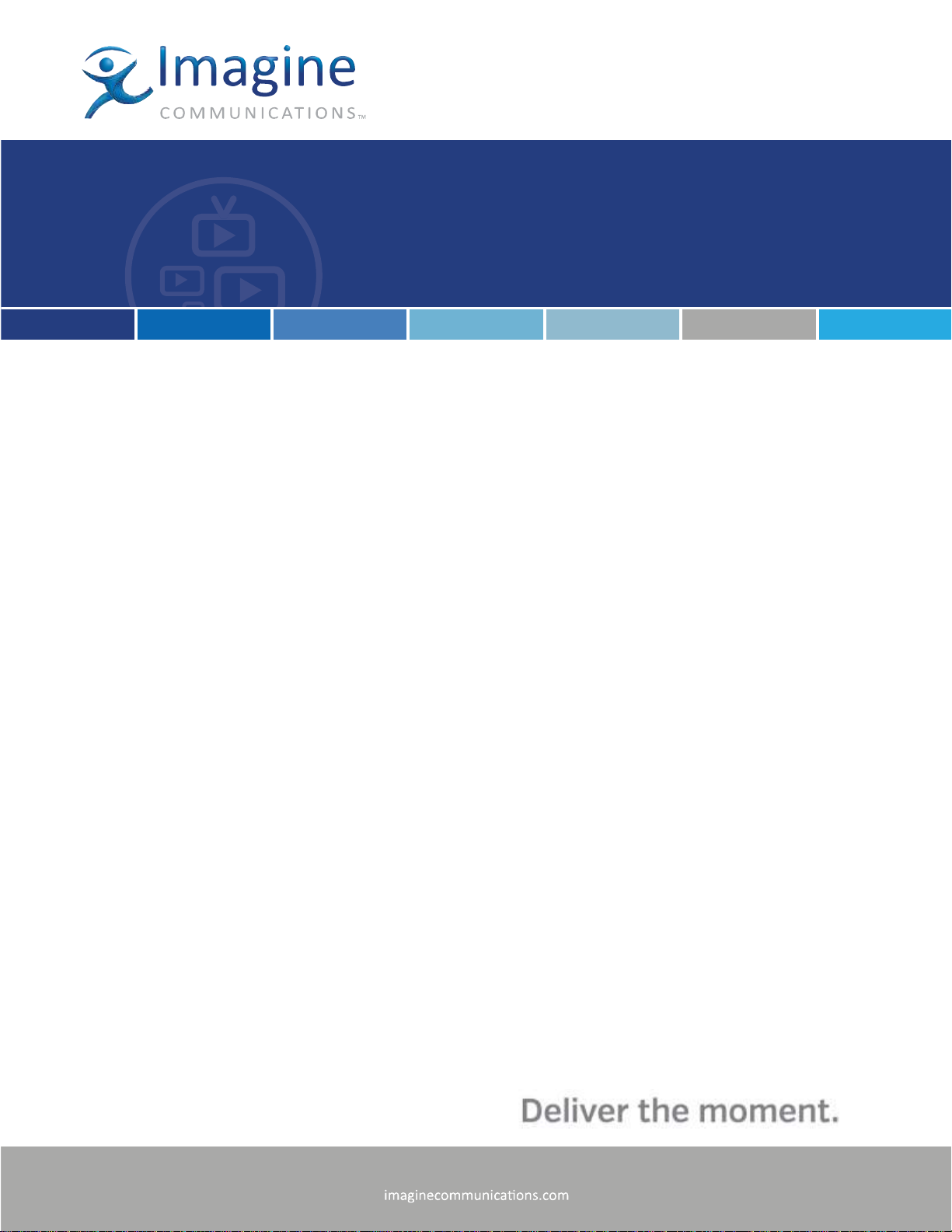
Button
Description
Power. Use the power button to apply or remove power from the internal power
supply to the server. When you turn off power using the button, you remove the
main power but keep standby power. You must unplug the system to remove all
power.
Reset. Use the reset button to reboot the system. You will need to use a pen or
another small pointed device to work this reset button.
Indicator
Description
Power.
Green indicates the system is on.
Amber indicates the system is off and plugged in.
HDD. Indicates IDE channel activity. When flashing, indicates SAS2/SATA drive
activity.
NIC 1. When flashing, this LED indicates network activity on GLAN1.
NIC 2. When flashing, this LED indicates network activity on GLAN2.
Power Failure. When flashing, this LED indicates a failure in one of the power
supplies.
Front Panel
Disk Drive LEDs
Each disk drive carrier has two LEDs.
Green or Blue. Each hard disk drive has either a green or blue LED that indicates drive activity. This
LED will blink on and off when the drive is being accessed.
Red. The red LED indicates a drive failure.
Front Panel Buttons
Front Panel LEDs
2014 Imagine Communications | All Rights Reserved Page 6 of 42
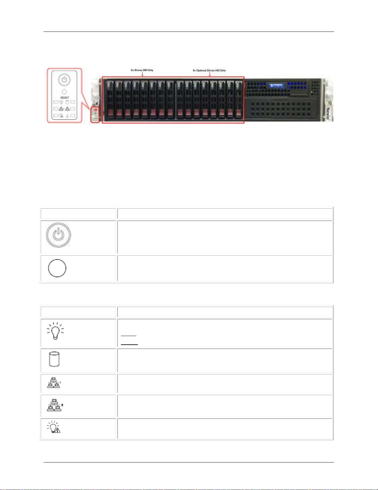
Nexio AMP® Gen-7 Chassis Components
Indicator
Description
Overheat / Fan Fail. When flashing, this LED indicates a fan failure. When on but
not flashing, this LED indicates an overheat condition which may be caused by an
airflow obstruction or ambient room temperature that is too high.
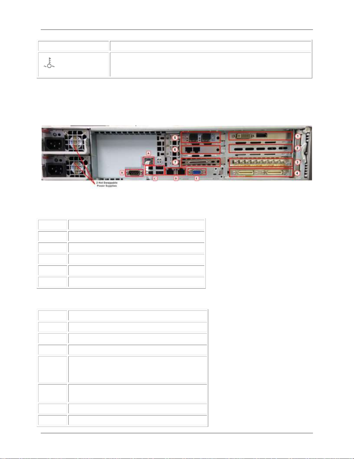
Index
Connector
A
IPMI LAN
B
RS-232 Serial LTC Input
C
4 USB 2.0 port connectors
D
Gigabit LAN 1 and LAN 2
E
Integrated VGA (Covered)
Index
Card
1
DVI port on left / Display port on right
2
Empty
3
Broadcast Video I/O
4
AES Audio Breakout ports.
1 - 2 Port (left) – first 2 record and playback channels
3 - 4 Port (right) – last 2 record and playback channels
5
HDI – SAS Host Adapter (no outputs)
HDX – Fibre Channel (with outputs)
6
Gigabit LAN 3 and LAN 4
7
AB4 card / VHDCI Breakout Cable to RS-422 and GPI
Back Panel
Back panel components are identified in the drawing. Please note that the exact placement of each
device may vary slightly from this drawing.
Motherboard I/O
The motherboard connectors are represented in the drawing and identified in the table.
Card Slots
2014 Imagine Communications | All Rights Reserved Page 7 of 42

Nexio AMP® Gen-7 Connectors and Ports
Connectors and Ports
The following connectors are provided with the AMP Gen-7 device. They are included in the shipping
container with the server.
VHDCI Breakout Cable (1)
RJ-12 to DB-9 Master Adapters (4)
RJ-12 to DB-9 Tributary Adapters (4)
MDR-X75HD-Coax Cables (2)
HD-BNC Male to BNC Female Cables (9)
AMP Gen-7 supports eight RS-422 serial ports. These ports are typically used for automation control
with one port assigned to each server channel.
The physical ports are provided via the VHDCI Breakout cable which attaches to the After Burner 4 (AB4)
card on the back of the server. The Breakout cable terminates in eight RJ-12 connectors pinned as
Master. Eight general purpose interface (GPI) connectors are also available via the Breakout cable.
The eight RJ-12 to DB-9 adapters can be used as necessary depending on the equipment you are
connecting to the Nexio system. These adapters have built-in master and tributary pin conversions and
are labeled Master and Tributary. You can use the adapters with the Breakout cable to effect a direct
connection to ADC or D-Series automation. You can also connect to most RS-422 controllers such as DNF
Controls, HiTech, JL Cooper and other automation device servers.
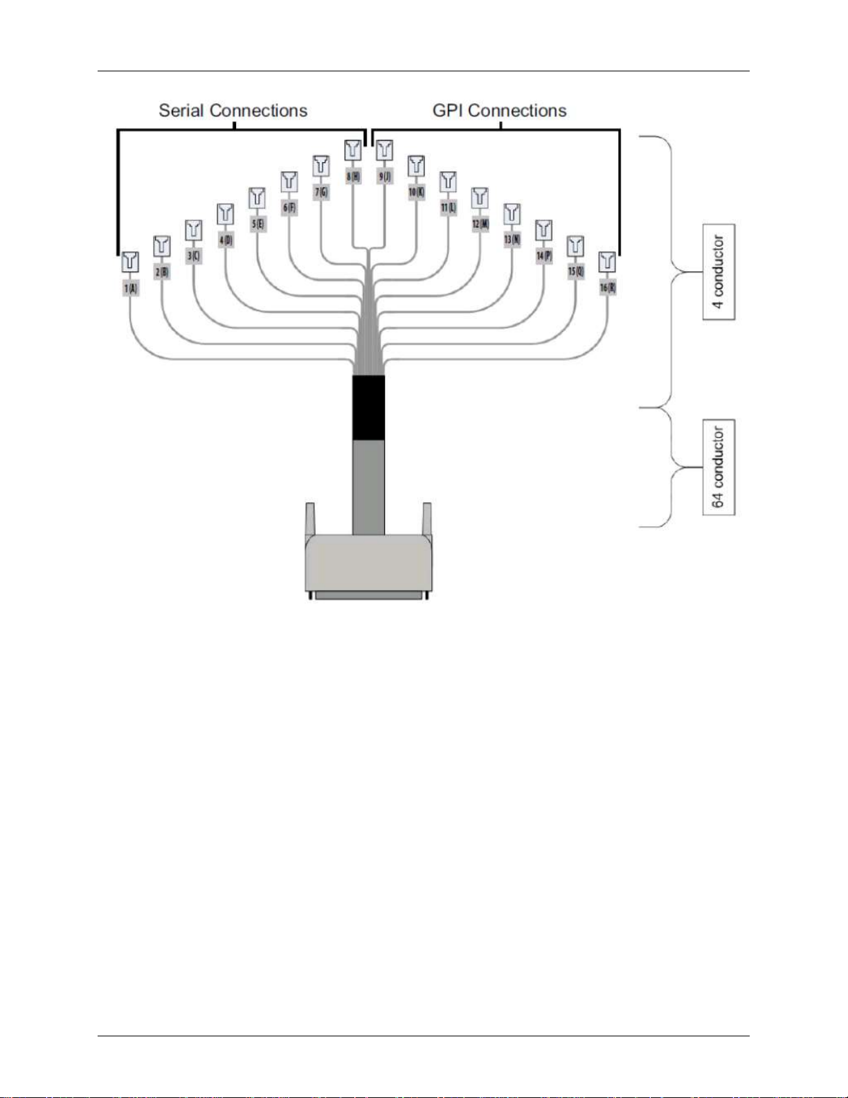
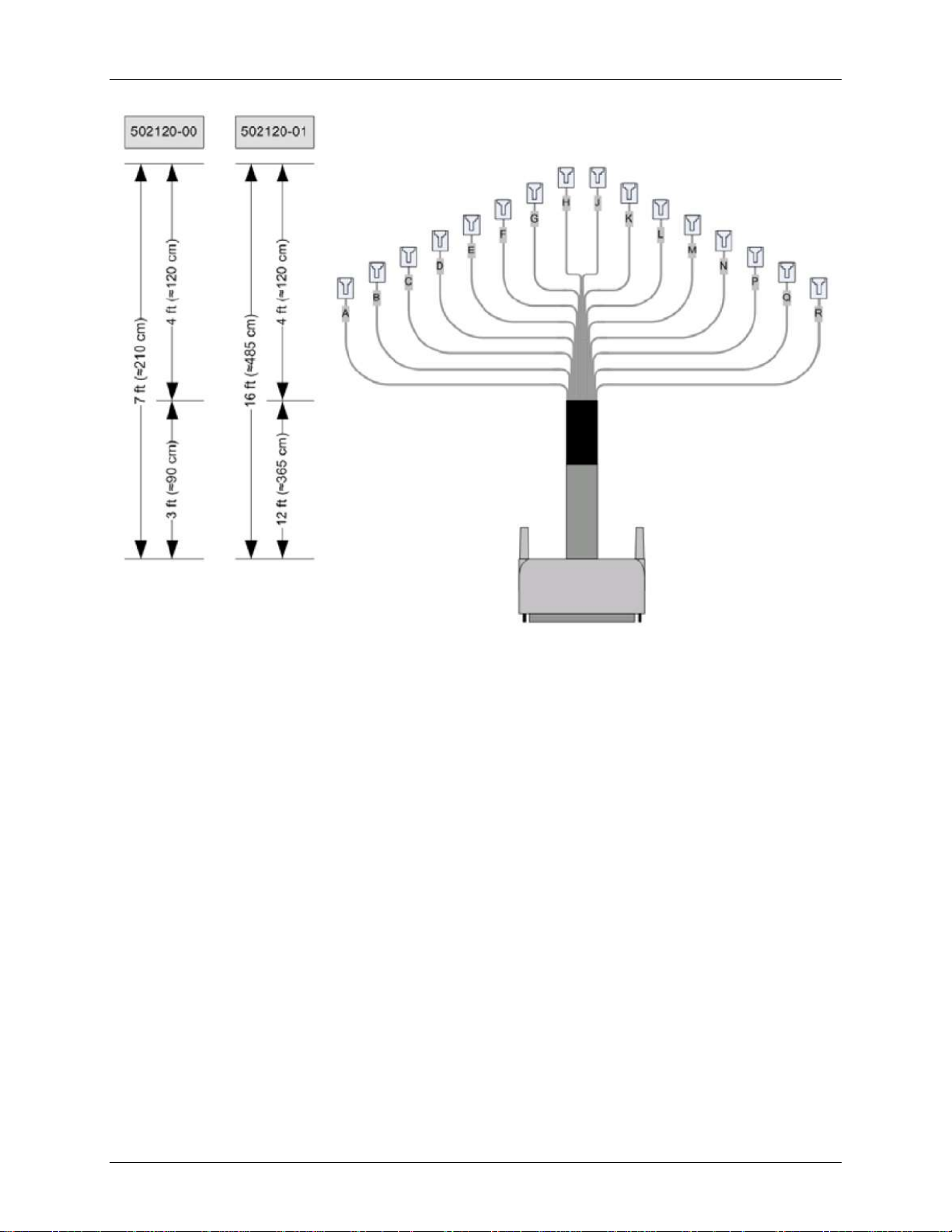
VHDCI Breakout Cable
The Breakout cable connects to the AB4 board on the server via a single VHDCI connector. On the other
end, 16 individual RJ connectors provide eight RS-422 serial ports and eight GPI ports.
Each port is labeled with a letter starting with 1 and A. (For example: 1A, 2A, 3A.) The letters O and I
have been omitted.
2014 Imagine Communications | All Rights Reserved Page 8 of 42
Nexio AMP® Gen-7 Connectors and Ports
VHDCI Breakout Cable Labels
Breakout Cable Lengths
Cables shipped with the Nexio device are 7 feet (210 cm) in total length. This includes a 3 feet (90 cm)
portion, a single cable from the VHDCI connector carrying all 16 ports and the remaining 4 feet (120 cm)
individual cables for each port.
The 7-ft breakout cable provided with the Nexio AMP device is ICC part number 502120-00.
A 16-ft breakout cable is available, ICC part number 502120-01.
2014 Imagine Communications | All Rights Reserved Page 9 of 42
Nexio AMP® Gen-7 Connectors and Ports
VHDCI Breakout Cable Dimensions
Breakout Cable Pinouts
64 pin VHDCI connector attaches to the AB4 port on the Nexio AMP.
16 RJ-12 connectors attach to other devices.
8 RS-422 serial ports are labeled A through H.
8 GPI ports are labeled J through R (no labels for the letters I or O.)
2014 Imagine Communications | All Rights Reserved Page 10 of 42
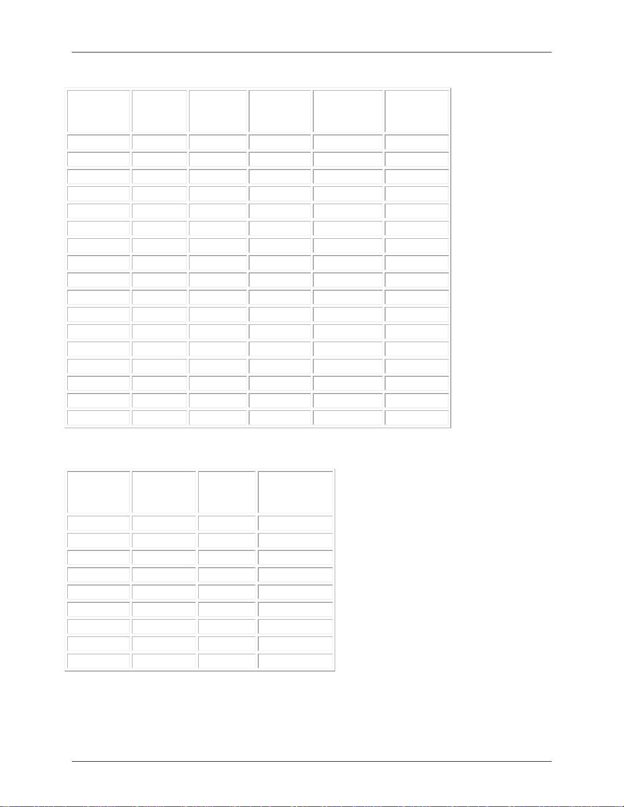
Nexio AMP® Gen-7 Connectors and Ports
VHDCI
Pin
AMP
Software
Ports
Signal
Flow
Direction
RJ-12
Pins
RJ-12
Cable End
Label
1, 35
GND
NA
empty
2, 36
1
TX+, TX- 1, 2
A
3, 37
1
RX+, RX-
4, 3
A
4, 38
2
TX+, TX- 1, 2
B
5, 39
2
RX+, RX-
4, 3
B
6, 40
3
TX+, TX- 1, 2
C
7, 41
3
RX+, RX-
4, 3
C
8, 42
4
TX+, TX- 1, 2
D
9, 43
4
RX+, RX-
4, 3
D
10, 44
5
TX+, TX- 1, 2
E
11, 45
5
RX+, RX-
4, 3
E
12, 46
6
TX+, TX- 1, 2
F
13, 47
6
RX+, RX-
4, 3
F
14, 48
7
TX+, TX- 1, 2
G
15, 49
7
RX+, RX-
4, 3
G
16, 50
8
TX+, TX- 1, 2
H
17, 51
8
RX+, RX-
4, 3
H
VHDCI
Pin
GPO
Label
RJ-12
Pins
RJ-12
Cable End
Label
18, 19
GPO1
1, 4 J 20, 21
GPO2
1, 4 K 22, 23
GPO3
1, 4 L 24, 25
GPO4
1, 4 M 26, 27
GPO5
1, 4 N 28, 29
GPO6
1, 4
P
30, 31
GPO7
1, 4 Q 32, 33
GPO8
1, 4 R 34
GND
RS-422 Port Connector Pinout Table
GPI-Out Port Connector Pinout Table
2014 Imagine Communications | All Rights Reserved Page 11 of 42
Nexio AMP® Gen-7 Connectors and Ports
VHDCI
Pin
GPI
Label
RJ-12
Pins
RJ-12
Cable End
Label
52, 53
GPI1, GND
2, 3 J 54, 55
GPI2, GND
2, 3 K 56, 57
GPI3, GND
2, 3 L 58, 59
GPI4, GND
2, 3 M 60, 61
GPI5, GND
2, 3 N 62, 63
GPI6, GND
2, 3 P 64, 65
GPI7, GND
2, 3 Q 66, 67
GPI8, GND
2, 3
R
68
GND
GPI-In Port Connector Pinout Table
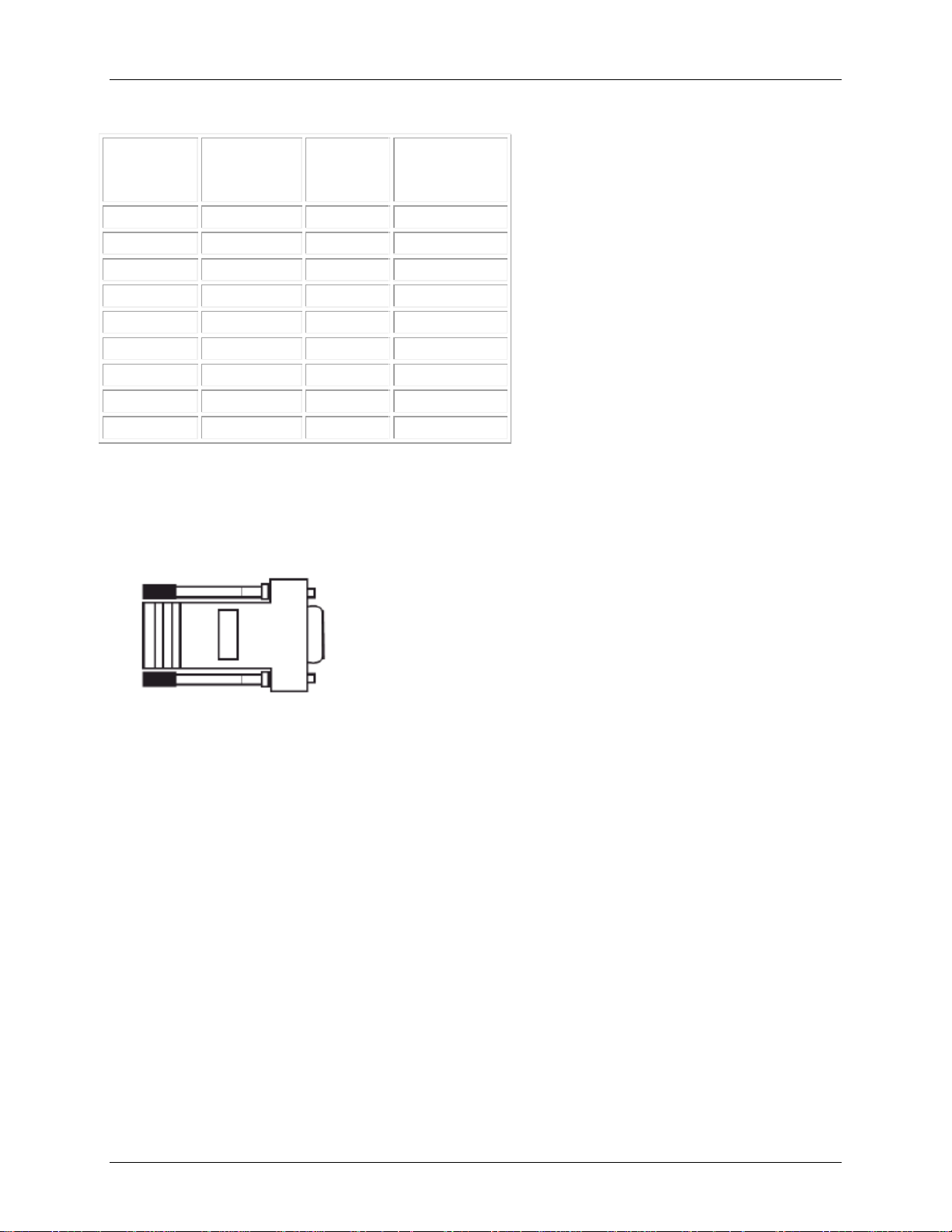
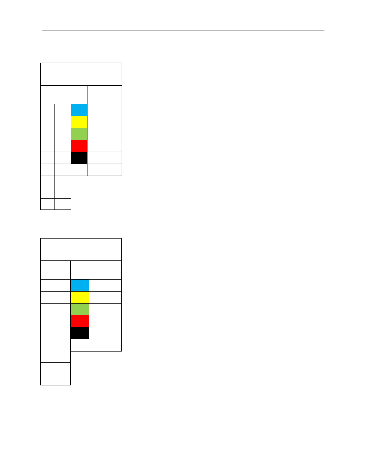
RJ-12 to DB-9 Adapters
The eight RJ-12 to DB-9 adapters have built-in master and tributary pin conversions and are labeled
Master and Tributary. You can use these adapters with the Breakout cable to connect the Nexio AMP
server to other devices.
2014 Imagine Communications | All Rights Reserved Page 12 of 42
Nexio AMP® Gen-7 Connectors and Ports
ICC 134-000722Q-00
MASTER
SMPTE
DB9M
RJ12F
7
Rx+ ← 1
Tx+ 2 Rx- ← 2
Tx- 8 Tx- → 3
Rx- 3 Tx+ → 4
Rx+ 9 Gnd ─ 5
NA 1 NA ─ 6
NA
4
NC
5
NC 6 NC
ICC 134-000721Q-00
TRIBUTARY
SMPTE
DB9M
RJ12F
3
Rx+ ← 1
Tx+ 8 Rx- ← 2
Tx- 2 Tx- → 3
Rx- 7 Tx+ → 4
Rx+ 9 Gnd ─ 5
NA 1 NA ─ 6
NA 4 NC
5
NC 6 NC
Master Adapters
Use the Master Adapters when you want to control the Nexio AMP server from an external device.
Tributary Adapters
Use the Tributary Adapters when you want to control an external device from the Nexio AMP.
2014 Imagine Communications | All Rights Reserved Page 13 of 42
 Loading...