

Imagine communications Infocaster Manager NM3200 Hardware Manual

Hardware Manual
Infocaster Manager™ NM3200
6/9/2014
175-700260-00

Infocaster Manager™ NM3200 Hardware Manual
Publication Information
© 2014 Imagine Communications.
Proprietary and Confidential.
Imagine Communications considers this document and its contents to be proprietary and confidential.
Except for making a reasonable number of copies for your own internal use, you may not reproduce this
publication, or any part thereof, in any form, by any method, for any purpose, or in any language other
than English without the written consent of Imagine Communications. All others uses are illegal.
This publication is designed to assist in the use of the product as it exists on the date of publication of
this manual, and may not reflect the product at the current time or an unknown time in the future. This
publication does not in any way warrant description accuracy or guarantee the use for the product to
which it refers. Imagine Communications reserves the right, without notice to make such changes in
equipment, design, specifications, components, or documentation as progress may warrant to improve
the performance of the product.
Trademarks
Infocaster™ and Infocaster Manager™ are trademarks or trade names of Imagine Communications or its
subsidiaries.
Microsoft® and Windows® are registered trademarks of Microsoft Corporation. All other trademarks and
trade names are the property of their respective companies.
Contact Information
Imagine Communications has office locations around the world. For domestic and international location
and contact information, visit our Contact page
(http://www.imaginecommunications.com/company/contact-us.aspx).
Support Contact Information
For domestic and international support contact information see:
Support Contacts (http://www.imaginecommunications.com/services/technical-support.aspx)
eCustomer Portal (http://support.imaginecommunications.com)
Academy Training (http://www.imaginecommunicationsacademy.com)
© 2014 Imagine Communications. Proprietary and Confidential. 6/9/2014 | Page 2

Infocaster Manager™ NM3200
Hardware Manual Contents
Contents
Preface ................................................................................................................... 5
Manual Information ................................................................................................................................. 5
Purpose ................................................................................................................................................. 5
Audience ............................................................................................................................................... 5
Writing Conventions ............................................................................................................................. 5
Unpacking/Shipping Information ............................................................................................................. 5
Safety Standards and Compliances .......................................................................................................... 6
Safety Terms and Symbols ................................................................................................................... 6
Restriction on Hazardous Substances (RoHS) Directive ....................................................................... 6
Waste from Electrical and Electronic Equipment (WEEE) Directive .................................................... 7
Safety Guidelines ...................................................................................................................................... 8
Electrical Safety Guidelines .................................................................................................................. 8
General Safety Guidelines .................................................................................................................... 9
ESD Safety Guidelines ........................................................................................................................... 9
Operation Safety Guidelines .............................................................................................................. 10
Introduction ......................................................................................................... 11
Main Features ......................................................................................................................................... 11
System Chassis ........................................................................................................................................ 11
Chassis ................................................................................................................................................ 11
Back Panel .......................................................................................................................................... 14
Get Started .......................................................................................................... 16
Packing List ............................................................................................................................................. 17
Chassis Components Installation ............................................................................................................ 18
Important Safety Guidelines .............................................................................................................. 18
Installation Tools ................................................................................................................................ 18
Accessory Kit....................................................................................................................................... 19
Install an HDD Removable Drive ........................................................................................................ 19
Remove the Chassis Cover ................................................................................................................. 20
HASP Dongle Internal Installation ...................................................................................................... 21
Access the Front Chassis Fans ............................................................................................................ 22
Access the Power Supply .................................................................................................................... 23
© 2014 Imagine Communications. Proprietary and Confidential. 6/9/2014 | Page 3

Infocaster Manager™ NM3200
Hardware Manual Contents
Chassis Rack Installation ......................................................................................................................... 25
Install the Chassis Slides ..................................................................................................................... 25
Rack Mount Safety Instructions ......................................................................................................... 26
Rack Mount the Chassis ..................................................................................................................... 26
GPI Triggers ............................................................................................................................................. 28
Serial Port GPI Trigger ........................................................................................................................ 28
USB GPI Trigger................................................................................................................................... 28
Before You Turn Your System On ........................................................................................................... 29
Security ................................................................................................................................................... 30
Maintenance ........................................................................................................ 31
Hot Swap Power Supplies ....................................................................................................................... 32
To replace the failed power supply module ....................................................................................... 32
Back Up Files ........................................................................................................................................... 32
Defragment Hard Drive .......................................................................................................................... 33
System Restore ....................................................................................................................................... 33
Recovery Solutions ............................................................................................................................. 33
Create Your Backup Media ................................................................................................................. 33
Recovery Options ............................................................................................................................... 33
Launch Recovery ................................................................................................................................ 34
Choose a Recovery Option ................................................................................................................. 34
Prevent Damage and Malfunction ......................................................................................................... 35
Hardware ............................................................................................................................................ 35
Anti-Virus Software ............................................................................................................................ 35
Operating System Updates ................................................................................................................. 35
Automatic Updates............................................................................................................................. 36
Specifications ....................................................................................................... 37
System Technical Specifications ............................................................................................................. 37
Power Supply Specifications ................................................................................................................... 37
© 2014 Imagine Communications. Proprietary and Confidential. 6/9/2014 | Page 4

Infocaster Manager™ NM3200
Term or Convention
Description
CAPS
Indicates a specific key on the keyboard, such as ENTER,
TAB, CTRL, ALT, DELETE
Code
Indicates variables or command-line entries, such as a
DOS entry or something you type into a field.
>
Indicates the direction of navigation through a hierarchy
of menus and windows.
hyperlink
Indicates a jump to another location within the electronic
document or elsewhere.
Note:
Indicates important information that helps to avoid and
troubleshoot problems.
Hardware Manual Preface
Preface
Manual Information
Purpose
This manual details the features, installation, operation, maintenance, and specifications of the NM3200
system.
Audience
This manual is written for engineers, technicians, and operators responsible for the system installation
and set up.
Writing Conventions
This manual adheres to the following writing conventions.
Writing Conventions
Unpacking/Shipping Information
Imagine Communications has carefully inspected, tested, and calibrated this product prior to shipment
to ensure years of stable and trouble free service.
Before you install and configure your system, follow these steps:
1. Check equipment for any visible damage that may have occurred during transit.
2. Confirm that you have received all items listed on the packing list.
© 2014 Imagine Communications. Proprietary and Confidential. 6/9/2014 | Page 5

Infocaster Manager™ NM3200
WARNING
Identifies conditions or practices that can result in personal
injury or loss of life—high voltage is present. Uninsulated
dangerous voltage within the product’s enclosure may be
sufficient to constitute a risk of electric shock to persons.
CAUTION
Identifies conditions or practices that can result in damage to
the equipment or other property. Important operating and
maintenance (servicing) instructions are included in the
literature accompanying the product.
Hardware Manual Preface
3. Contact your Imagine Communications sales representative if any parts are missing.
4. Contact the carrier if any item is damaged.
5. Remove all packaging material from the product and its associated components before you install
the unit.
Keep at least one set of original packaging, in the event that you need to return a product for servicing.
If the original packaging is not available, you can purchase replacement packaging from Imagine
Communications at a modest cost or supply your own packaging as long as it meets the following
criteria:
The packaging must be able to withstand the weight of the product.
The product must be held rigid within the packaging.
There must be at least two inches (5 cm) of space between the product and the container.
The corners of the product must be protected.
If the product is still within the warranty period, Imagine Communications will return the product to you
prepaid after servicing.
Safety Standards and Compliances
Safety Terms and Symbols
This manual uses the following safety terms and symbols to identify certain conditions or practices.
Restriction on Hazardous Substances (RoHS) Directive
Directive 2002/95/EC–commonly known as the European Union (EU) Restriction on Hazardous
Substances (RoHS)–sets limits on the use of certain substances found in electrical and electronic
equipment. The Directive takes effect on July 1, 2006, and it refers to the following hazardous
substances:
© 2014 Imagine Communications. Proprietary and Confidential. 6/9/2014 | Page 6
Infocaster Manager™ NM3200
Hardware Manual Preface
Lead (Pb)
Mercury (Hg)
Cadmium (Cd)
Hexavalent Chromium (Cr-V1)
Polybrominated Biphenyls (PBB)
Polybrominated Diphenyl Ethers (PBDE)
All relevant Imagine Communications products either comply with the legislation or are exempt. For
example, spare parts supplied for the repair and upgrade of equipment sold before July 1, 2006 are
exempt from the legislation.
Figure 1: RoHS Compliant Symbol
Waste from Electrical and Electronic Equipment (WEEE)
Directive
The European Union (EU) Directive 2002/96/EC on Waste from Electrical and Electronic Equipment
(WEEE) deals with the collection, treatment, recovery, and recycling of electrical and electronic waste
products. The objective of the WEEE Directive is to assign the responsibility for the disposal of
associated hazardous waste to either the producers or users of these products. Producers or users are
required to recycle electrical and electronic equipment at end of its useful life, and must not dispose of
the equipment in landfills or by using other unapproved methods.
In accordance with this EU Directive, Imagine Communications has affixed labels indicating that such
products must be properly recycled. Contact your local Imagine Communications sales representative
for information on returning these products for recycling. Imagine Communications equipment that
complies with the EU directive will be marked with a WEEE-compliant symbol, as shown below.
Figure 2: WEEE Compliance Symbol
© 2014 Imagine Communications. Proprietary and Confidential. 6/9/2014 | Page 7

Infocaster Manager™ NM3200
WARNING
To avoid electrical shock, check the power cords properly.
WARNING
Adhere to the following Electrical Safety Guidelines to avoid
possible damages to the system or injury to yourself.
Hardware Manual Preface
Safety Guidelines
Adhere to the following safety guidelines to avoid personal injury or damage to your system.
Electrical Safety Guidelines
Power Cords
Use the exact type of power cords as required.
Be sure to use power cord(s) that came with safety certifications.
The power cord(s) must be compliant with the AC voltage requirements in your region.
The power cord plug cap must have an electrical current rating that is at least 125% of the electrical
current rating of this product.
The power cord plug cap that plugs into the AC receptacle on the power supply must be an IEC 320,
sheet C13, type female connector.
Plug the Power cord(s) into a socket that is properly grounded before turning on the power.
This hardware contains hazardous voltage levels. To avoid electrical shock, disconnect all cords
before accessing the system chassis or its components.
General Electrical Safety Guidelines
Be aware of the locations of the power switches on the chassis and in the room, so you can
disconnect the power supply if an accident occurs.
Take extra precautionary measures when working with high voltage components. It is not
recommended to work alone.
Before removing or installing main system components, be sure to disconnect the power first. Turn
off the system before you disconnect the power supply.
Use only one hand when working with powered-on electrical equipment to avoid possible electrical
shock.
Use rubber mats specifically designed as electrical insulators when working with computer systems.
The power supply or power cord must include a grounding plug and must be plugged into grounded
outlets.
This product is suitable for connection to IT power sources.
CAUTION - RISK OF EXPLOSION IF BATTERY IS REPLACED BY AN INCORRECT TYPE. DISPOSE OF USED
BATTERIES ACCORDING TO THE INSTRUCTIONS.
Make sure not to install the motherboard battery upside down to avoid possible explosion. Make
sure that the positive side should be facing up on the motherboard.
© 2014 Imagine Communications. Proprietary and Confidential. 6/9/2014 | Page 8
Infocaster Manager™ NM3200
WARNING
Adhere to the following General Safety Guidelines to ensure
your personal safety.
CAUTION
Electric Static Discharge (ESD) can damage electronic
components. To prevent damage to your system board, it is
important to handle it very carefully.
Hardware Manual Preface
CAUTION – Do not open the enclosures of power supplies or CD ROM to avoid injury.
Protective Earth Requirements
The building installation shall provide a means for connection to protective earth; and
The equipment is to be connected to that means; and
A service person shall check whether or not the socket-outlet from which the equipment is to be
powered provides a connection to the building protective earth. If not, the service person shall
arrange for the installation of a protective earthing conductor from the separate protective
earthing terminal to the protective earth wire in the building.
General Safety Guidelines
Equipment is for use only in restricted access locations where only trained personnel have access.
Keep the area around the the chassis clean and free of clutter.
To avoid injuries to the back, be sure to use your leg muscles, keep your back straight, and bend
your knees, when lifting the system.
Avoid wearing loose clothing to preventing it from coming into contact with power circuits.
After removing the components or chassis cover from the system, place them on a table for
safeguard.
Be sure to remove any jewelry or metal objects before working on the chassis to avoid short circuits
should these objects come into contact with power circuits.
After accessing the interior of the chassis, be sure to replace and secure the chassis cover.
ESD Safety Guidelines
The following measures are generally sufficient to protect against Electric Statics Discharge (ESD).
Use a grounded wrist strap designed to prevent static discharge.
Keep all components and printed circuit boards (PCBs) in their anti-static bags until ready for use.
Touch a grounded metal object before removing the board from the anti-static bag.
Do not let components or PCBs come into contact with your clothing, which may retain a charge
even if you are wearing a wrist strap.
Touch a grounded metal object before removing the board from the anti-static bag.
Handle a board by its edges only; do not touch its components, peripheral chips, memory modules
or contacts.
When handling chips or modules, avoid touching their pins.
© 2014 Imagine Communications. Proprietary and Confidential. 6/9/2014 | Page 9

Infocaster Manager™ NM3200
CAUTION
Do not open the casing of a power supply. Power supplies can
only be accessed and serviced by a qualified technician of the
manufacturer.
Hardware Manual Preface
Put the motherboard and peripherals back into their anti-static bags when not in use.
For grounding purposes, make sure your computer chassis provides excellent conductivity between
the power supply, the case, the mounting fasteners and the motherboard.
Operation Safety Guidelines
Adhere to the following safety guidelines to avoid personal injury when accessing the chassis.
1. Turn off all peripheral devices connected to the chassis.
2. Power off the system.
3. Unplug all power cords from the system or wall outlets.
4. Disconnect all the cables and label the cables for easy identification.
5. Use a grounded wrist strap designed to prevent static discharge when handling components.
© 2014 Imagine Communications. Proprietary and Confidential. 6/9/2014 | Page 10
Infocaster Manager™ NM3200
Hardware Manual Introduction
Introduction
This chapter provides an introduction to the NM3200 systems, and includes the following topics:
Main Features (on page 11)
Front Panel Components (on page 12)
Back Panel (on page 14)
Main Features
Your NM3200 system works with publishers and players to distribute and control content output.
These are the main features of your NM3200 system.
Manage players from one central location via TCP/IP, Satellite, or LAN.
Control individual or groups of players simultaneously.
Update content remotely to keep the information current.
View playback remotely.
Control Choices: GPI, automation, manual.
Hot-swappable hard drives.
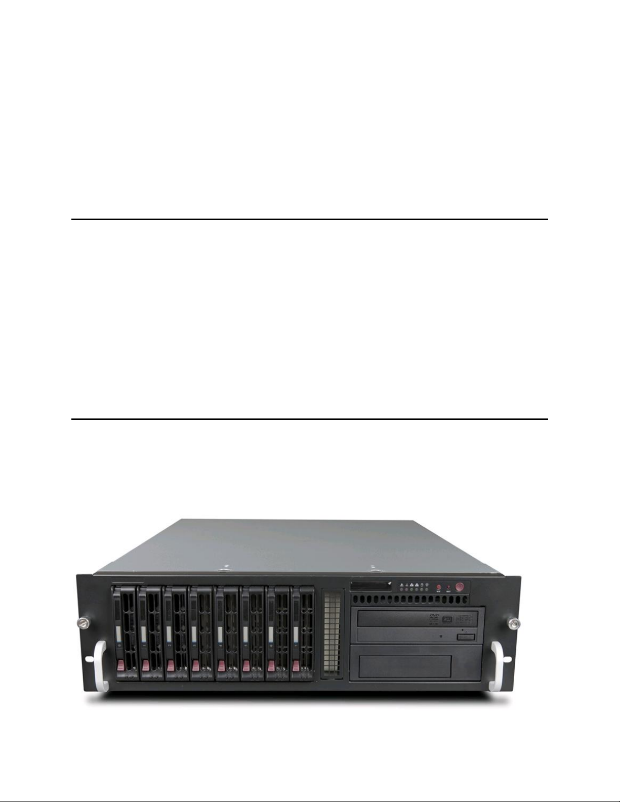
System Chassis
Chassis
The following figure shows the NM3200 system.
© 2014 Imagine Communications. Proprietary and Confidential. 6/9/2014 | Page 11
Infocaster Manager™ NM3200
Hardware Manual Introduction
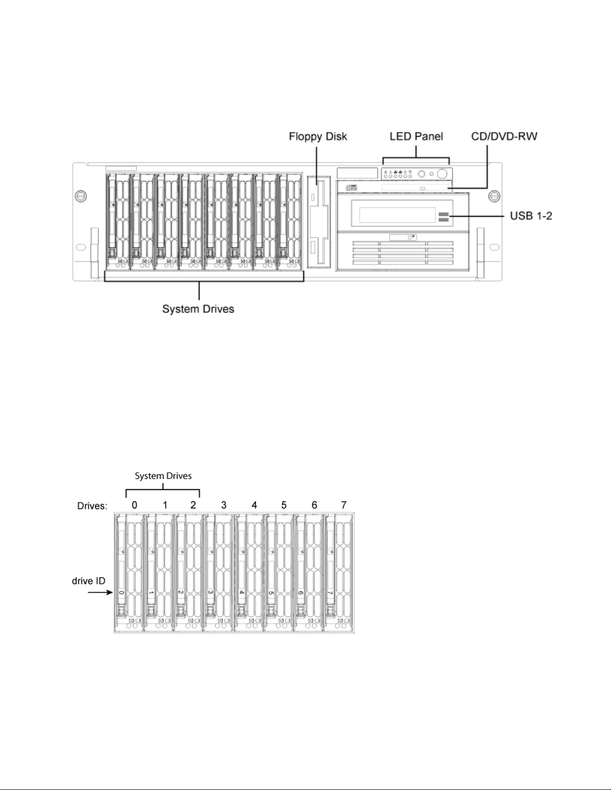
Front Panel Components
The front panel provides access to the hot-swappable system drives and the CD/DVD-RW drive.
System Drives
The NM3200 system drives consist of three 1 TB SATA drives in RAID 5 linked together for a total drive
capacity of 2.0 TB.
Starting with Drive 0, the three-drive array is partitioned into three partitions:
Recovery,
100 GB for the operating system,
and the remaining space is available for media storage across all drives.
Front LED Panel
NM3200 has six panel LEDs indicating the system status. The LED panel also has the system power
On/Off, system reset (restart), and alarm reset buttons.
© 2014 Imagine Communications. Proprietary and Confidential. 6/9/2014 | Page 12
 Loading...