

Imagine communications Selenio 6800, HMX6800+BC8 Installation And Operation Manual

Installaon and Operaon Manual
Selenio 6800™ HMX6800+BC8
Audio Multiplexers
Edion B
175-000343-00
Delivering the Moment

HMX6800+BC8
Audio Multiplexers
Installation and Operation Manual
Edition B
November 2007


Content s
Preface
Manual Information .................................. .................................... ... ..... vii
Purpose ...........................................................................................vii
Audience ........................................................................................ vii
Revision History ............................................................................vii
Writing Conventions .....................................................................viii
Obtaining Documents ...................................................................viii
Unpacking/Shipping Information ..........................................................ix
Unpacking a Product ....................................................................... ix
Product Servicing ............................................................................ ix
Returning a Product ........................................................................ ix
Restriction on Hazardous Substances (RoHS) Compliance ....................x
Waste from Electrical and Electronic Equipment (WEEE) Compliance xi
Safety .................................................................................................... xii
Safety Terms and Symbols in this Manual ........... ... ......................xii
Chapter 1: Introduction
Overview ..................................................................................................1
Product Description ..................................................................................2
Module Descriptions ................................................................................3
Front Module ....................................................................................3
Back Connectors ...............................................................................5
Breakout Cables ................................................................................6
RS-422/RS-232 Cable .....................................................................10
Signal Flow .................. ... ..................................... ..................................11
Chapter 2: Installation
Overview ................................................................................................13
HMX6800+BC8 Installation and Operation Manual iii

Contents
Maximum 6800+ Frame Power Ratings ...............................................14
Unpacking the Module .......................................................................... 15
Preparing the Product for Installation ............................................15
Checking the Packing List .............................................................15
Setting Jumper CJ1 for Local or Remote Control .................................16
Installing 6800+ Modules ..................................................................... 17
Required Frames and Back Connector Types ................................17
Installing and Removing Modules ................................................. 17
Upgrading Module Firmware ................................................................ 18
Upgrading the Firmware ................................................................18
Correcting a Failed Upgrading Procedure ..................................... 21
Chapter 3: Operation
Overview ............................................................................................... 25
Operating Notes ..................................................................................... 26
Q-SEE Compliant Thumbnails ......................................................26
Activating Multiplexer Functions .........................................................27
Audio Test Tones ...........................................................................27
Audio Embedding Modes ..............................................................27
Audio Embedding Errors ............................................................... 32
Input Audio Rate ............................................................................32
Cross-Functional Parameter Changes ...................................................33
ADS Clean Parameter ....................................................................33
PCM/Non-PCM Settings ................................................................34
Channel Word Length ....................................................................34
Parameter Availability based on Operating Mode ......................... 35
Changing Parameter Settings ................................................................ 36
Changing Parameter Settings using Card-Edge Controls .............. 36
Setting HMX6800+BC8 Control Parameters ................................38
Changing Parameter Settings using CCS Software .......................49
Setting HMX6800+BC8 Remote Control Parameters ................... 50
LEDs and Alarms ..................................................................................60
Monitoring LEDs ....... ....................................................................60
Module Status LEDs ......................................................................61
Alarms ............................................................................................ 62
Chapter 4: Specifications
Overview ............................................................................................... 65
Inputs ..................................................................................................... 66
iv HMX6800+BC8 Installation and Operation Manual

SDI Video Input ..............................................................................66
AES Input .................................................................................... ...66
Outputs ...................................................................................................67
SDI Video Output ...........................................................................67
RS-232/RS-422 ......................................................................................68
Propagation Delay ..................................................................................68
Power Consumption ............................................. ..................................68
Operating Temperature ..........................................................................68
Appendix A: Audio Bit Manipulation
Overview ................................................................................................69
Manipulating Channel Status Bits (C-Bit) .............................................70
Manipulating Validity and User Bits (V-Bit and U-Bit) ........................73
Identifying Audio Characteristics (Audio Sampling Frequency and Word
Length) ...................................................................................................74
Appendix B: Communication and Control
Troubleshooting Tips
Overview ................................................................................................75
General Troubleshooting Steps ..............................................................76
Software Communication and Control Issues ........................................77
+ Pilot Lite Fails to Communicate with Installed Modules ...........77
+ Pilot Lite Does Not Find All Modules in Frame ........................78
+ Pilot Lite or CCS Software Application Not Responding ..........79
+ Pilot Lite Cannot Control a Module Showing
in the Control Window ...................................................................79
+ Pilot Lite Reports “Not Ready” Status .......................................79
CCS Software Application or Remote Control Panel Does Not
Communicate with Module ............................................................80
Alarm Query Fails When a Device Reboots ...................................80
Hardware Communication and Control Issues ......................................81
Frames Fail to Communicate with the PC after a Power Failure ...81
Module Does Not Seem to Work ....................................................81
Contacting Customer Service .................................................................81
Contents
Index
Keywords ...............................................................................................83
HMX6800+BC8 Installation and Operation Manual v

Contents
vi HMX6800+BC8 In stallation and Operation Manual

Manual Information
Purpose
This manual details the features, installation, operation, maintenance,
and specifications for the HMX6800+BC8 Audio Multiplexers.
Preface
Audience
Revision History
This manual is written for engineers, technicians, and operators
responsible for installation, setup, maintenance, and/or operation of the
HMX6800+BC8
Table P-1. Revision History of Manual
Edition Date Comments
A February 2007 Initial release
B November 2007 Update breakout cable information
Audio Multiplexers.
HMX6800+BC8 Installation and Operation Manual vii

Preface
Note
Writing Conventions
To enhance your understanding, the authors of this manual have
adhered to the following text conventions:
Table P-2. Writing Conventions
Term or
Convention
Bold Indicates dialog boxes, property sheets, fields, buttons,
Italics Indicates E-mail addresses, the names of books or
CAPS Indicates a specific key on the keyboard, such as
Code Indicates variables or command-line entries, such as a
> Indicates the direction of navigation through a hierarchy
hyperlink Indicates a jump to another location within the
Internet address
Description
check boxes, list boxes, combo boxes, menus,
submenus, windows, lists, and selection names
publications, and the first instances of new terms and
specialized words that need emphasis
ENTER, TAB, CTRL, ALT, or DELETE
DOS entry or something you type into a field
of menus and windows
electronic document or elsewhere
Indicates a jump to a Web site or URL
Indicates important information that helps to avoid and
troubleshoot problems
Obtaining Documents
Product support documents can be viewed or downloaded from our
website. Alternatively , co ntact your Customer Service representative to
request a document.
viii HMX6800+BC8 Installation and Operation Manual

Unpacking/Shipping Information
Unpacking a Product
This product was carefully inspected, tested, and calibrated before
shipment to ensure years of stable and trouble-free service.
1. Check equipment for any visible damage that may have occurred
during transit.
2. Confirm that you have received all items listed on the packing list.
3. Contact your dealer if any item on the packing list is missing.
4. Contact the carrier if any item is damaged.
5. Remove all packaging material from the product and its associated
components before you install the unit.
Keep at least one set of original packaging, in the event that you need to
return a product for servicing.
Product Servicing
Preface
Except for firmware upgrades, HMX6800+BC8 modules are not
designed for field servicing. All hardware upgrades, modifications, or
repairs require you to return the modules to the Customer Service
center.
Returning a Product
In the unlikely event that your product fails to operate properly, please
contact Customer Service to obtain a Return Authorization (RA)
number, then send the unit back for servicing.
Keep at least one set of original packaging in the event that a product
needs to be returned for service. If the original package is not available,
you can supply your own packaging as long as it meets the following
criteria:
• The packaging must be able to withstand the product’s weight.
• The product must be held rigid within the packaging.
• There must be at least 2 in. (5 cm) of space between the product and
• The corners of the product must be protected.
the container.
HMX6800+BC8 Installation and Operation Manual ix

Preface
Ship products back to us for servicing prepaid and, if possible, in the
original packaging material. If the product is still within the warranty
period, we will return the product prepaid after servicing.
Restriction on Hazardous Substances (RoHS)
Compliance
Directive 2002/95/EC—commonly known as the European Union (EU)
Restriction on Hazardous Substances (RoHS)—sets limits on the use of
certain substances found in electrical and electronic equipment. The
intent of this legislation is to reduce the amount of hazardous chemicals
that may leach out of landfill sites or otherwise contaminate the
environment during end-of-life recycling. The Directive, which took
effect on July 1, 2006, refers to the following hazardous substances:
• Lead (Pb)
• Mercury (Hg)
• Cadmium (Cd)
• Hexavalent Chromium (Cr-V1)
• Polybrominated Biphenyls (PBB)
• Polybrominated Diphenyl Ethers (PBDE)
According to this EU Directive, all products sold in the European Union
will be fully RoHS-compliant and “lead-free.” (See our website for
more information on dates and deadlines for compliance.) Spare parts
supplied for the repair and upgrade of equipment sold before
July 1, 2006 are exempt from the legislation. Equipment that complies
with the EU directive will be marked with a RoHS-compliant emblem,
as shown in Figure P-1.
Figure P-1. RoHS Compliance Emblem
x HMX6800+BC8 Installation and Operation Manual

Waste from Electrical and Electronic
Equipment (WEEE) Compliance
The European Union (EU) Directive 2002/96/EC on Waste from
Electrical and Electronic Equipment (WEEE) deals with the collection,
treatment, recovery, and recycling of electrical and electronic waste
products. The objective of the WEEE Directive is to assign the
responsibility for the disposal of associated hazardous waste to either
the producers or users of these products. As of August 13, 2005, the
producers or users of these products were required to recycle electrical
and electronic equipment at end of its useful life, and may not dispose
of the equipment in landfills or by using other unapproved methods.
(Some EU member states may have different deadlines.)
In accordance with this EU Directive, companies selling electric or
electronic devices in the EU will affix labels indicating that such
products must be properly recycled. (See our website for more
information on dates and deadlines for compliance.) Contact your local
sales representative for information on returning these products for
recycling. Equipment that complies with the EU directive will be
marked with a WEEE-compliant emblem, as shown in Figure P-2.
Preface
Figure P-2. WEEE Compliance Emblem
HMX6800+BC8 Installation and Operation Manual xi
Preface
Safety
Carefully review all safety precautions to avoid injury and prevent
damage to this product or any products connected to it. If this product is
rack-mountable, it should be mounted in an appropriate rack using the
rack-mounting positions and rear support guides provided. It is
recommended that each frame be connected to a separate electrical
circuit for protection against circuit overloading. If this product relies
on forced air cooling, it is recommended that all obstructions to the air
flow be removed prior to mounting the frame in the rack.
If this product has a provision for external earth grounding, it is
recommended that the frame be grounded to earth via the protective
earth ground on the rear panel.
IMPORTANT! Only qualified personnel should perform service
procedures.
Safety Terms and Symbols in this Manual
WARNING
Statements identifying conditions or
practices that may result in personal injury
or loss of life. High voltage is present.
CAUTION
Statements identifying conditions or
practices that can result in damage to the
equipment or other property.
xii HMX6800+BC8 Installation and Oper ation Manual

Overview
Chapter 1
Introduction
The HMX6800+BC8 HD/SD Audio Multiplexers embed 8 AES audio
signals, in both balanced and unbalanced formats, into a single 1.5 Gb/s
HD or 270 Mb/s SD video stream. Following SMPTE specifications,
this embedder can embed up to eight AES audio signals into four
groups in the horizontal ancillary region of the HD-SDI or SD-SDI
output signal. The sample rate conversion can be disabled for
Dolby E®/compressed audio compliancy.
HMX6800+BC8 modules auto-detect between HD-SDI and SD-SDI
signals with full channel selection per HD or SD signal. Built-in video
and audio processing amplifiers allow for full control over the picture
and sound.
Each HMX6800+BC8 includes a module-specific breakout cable that
expands the number of available connections beyond what would fit on
a standard two-slot back connector. The breakout cable includes an
RS-422 serial connector to embed metadata.
HMX6800+BC8 modules can be controlled at the card edge; or
controlled and monitored through Pilot Lite, Pilot, Navigator, and
CCS-compliant control panels.
The following topics are described in this chapter:
• “Product Description” on page 2
• “Module Descriptions” on page 3
• “Breakout Cables” on page 6
• “Signal Flow” on page 11
HMX6800+BC8 Installation and Operation Manual 1

Chapter 1: Introduction
Product Description
HMX6800+BC8 modules have the following features:
• Automatic detection of all SMPTE 292M HDTV video standards
and SMPTE 259M 525/625 component video standards
• 16-, 20-, or 24-bit audio processing (selectable word length in
channel pairs)
• Audio test tone generator
• Programmable audio delays (up to 1.3 s)
• Inputs:
• SMPTE 292M HD-SDI or SMPTE 259M SD-SDI input
• Eight unbalanced AES digital audio or eight balanced AES
digital audio inputs
• Four SMPTE 292M HD-SDI with SMPTE 299M embedded audio
or SMPTE 259M SD-SDI with SMPTE 272M embedded audio
outputs
• Video delay for 1 video stream (up to 5 frames for HD and 25
frames for SD)
• Sample rate conversion disable on AES inputs for Dolby /
compressed audio embedding
• Optional ancillary data space cleaning mode before embedding
• 24-bit AES input audio embedding
• Data embedding (Dolby-E metadata)
• HD and SD video processing amplifier with controls for luminance
gain, luminance offset, chrominance gain, chrominance offset,
white clip, black clip, and hue (SD only)
• Audio processing amplifier with controls for delay, gain, invert,
channel multiplexing, and averaging
• Thumbnail streaming of output video, when installed in an
FR6802+QXF frame that also contains a 6800+Eth resource
module
• Card-edge LEDs to indicate signal presence (both audio and video)
and module failure
• Serial and Ethernet remote control and monitoring
2 HMX6800+BC8 Installation and Operation Manual
Module Descriptions
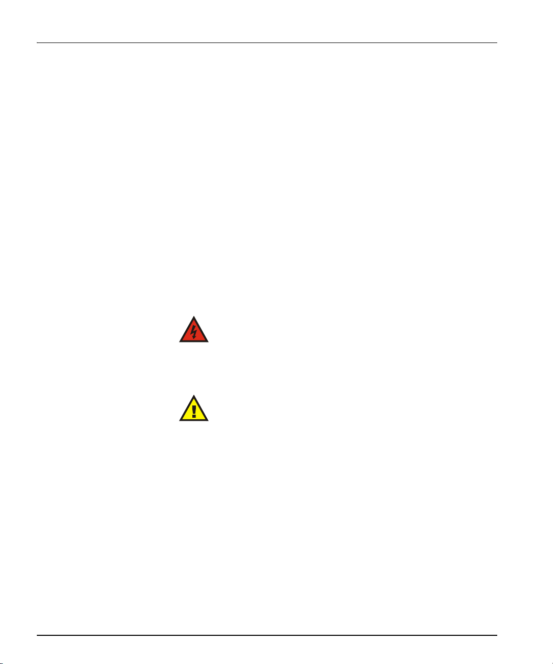
Module
status
LEDs
Hex switch
(Mode select
rotary switch)
Navigation
toggle
switch
Monitoring
LEDs
Remote/
local control
jumper
Extractor
handle
Control
LEDs
Front Module
Figure 1-1 is a generic top-front view of a typical 6800+ module and
shows the general location of standard LEDs, controls, and jumpers.
Chapter 1: Introduction
Figure 1-1. Typical 6800+ Module
Table 1-1 on page 4 briefly describes generic 6800+ LEDs, switches,
and jumpers. See “Operation” on page 25 for more information on
specific HMX6800+BC8
HMX6800+BC8 Installation and Operation Manual 3
module controls, LEDs, and jumpers.

Chapter 1: Introduction
Table 1-1. Generic 6800+ Module Features
Feature Description
Module status
LEDs
Mode select
rotary switch
Navigation
toggle switch
Control LEDs Various lighting combinations of these control LEDs
Monitoring
LEDs
Local/Remote
control jumper
Various color and lighting combinations of these LEDs
indicate the module state.
page 61 for more information.
This switch selects between various control parameters.
This switch navigates up and down through the available
control parameters:
• Up: Decrease
• Down: Increase
(sometimes referred to as “Bank Select LEDs”) indicate
the currently selected bank.
for more information.
Each 6800+ module has a number of LEDs assigned to
indicate varying states/functions.
LEDs” on page 60 for a description of these LEDs.
• Local: Locks out external control panels and allows
card-edge control only; limits the functionality of
remote software applications to alarm monitoring
• Remote: Allows remote or local (card-edge)
configuration, operation, and monitoring of the
See “Module Status LEDs” on
See Table 3-7 on page 36
See “Monitoring
HMX6800+BC8
4 HMX6800+BC8 Installation and Operation Manual
Not connected
Breakout Cable
- 8 AES inputs
- Metadata input
- DARS input
HD/SD-SDI IN
HD/SD-SDI OUT1
HD/SD-SDI OUT2
HD/SD-SDI OUT3
HD/SD-SDI OUT4
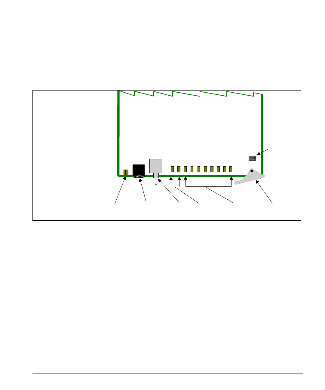
Back Connectors
HMX6800+BC8 Back Connector for FR6802+ Frame
Figure 1-2 shows the double-slot back connector used by the
HMX6800+BC8 when installed in an FR6802+QXF frame.
Chapter 1: Introduction
HMX6800+BC8 Installation and Operation Manual 5
Figure 1-2. HMX6800+BC8 Back Connector
Chapter 1: Introduction
DARS balanced in
Unbalanced AES 1 out
Unbalanced AES 2 out
Unbalanced AES 3 out
Unbalanced AES 4 out
Unbalanced AES 1 in
Unbalanced AES 2 in
Unbalanced AES 3 in
Unbalanced AES 4 in
DARS in
Data I/O
Genlock
Serial
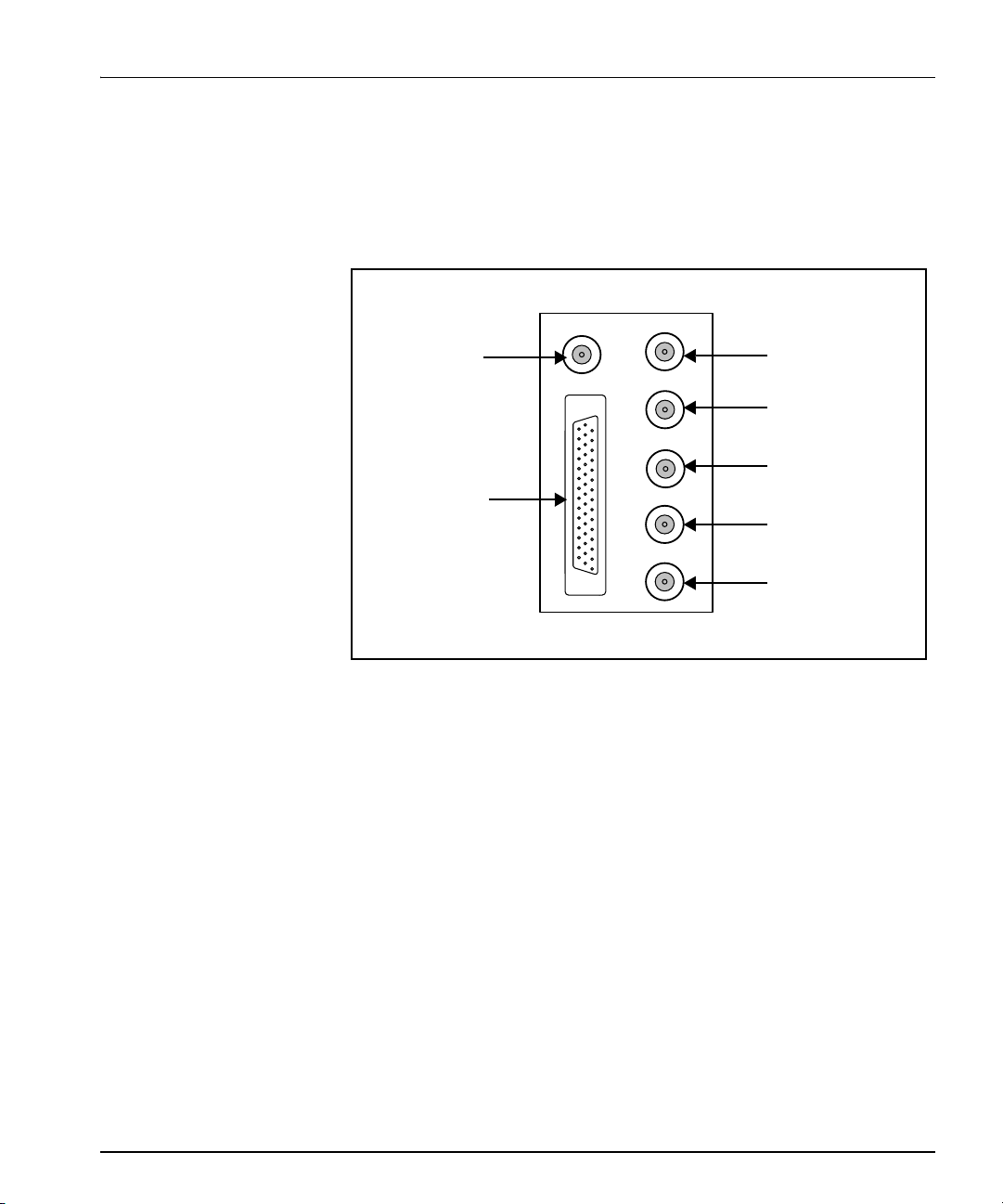
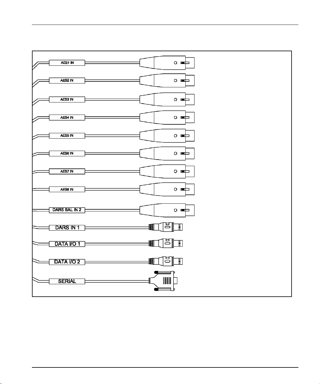
Breakout Cables
Each HMX6800+BC8 comes with an unbalanced-audio breakout cable
similar to the one pictured in Figure 1-3. An optional balanced-audio
breakout cable, as seen in Figure 1-4 on page 7. For ordering
information, see Figure 2-2 on page 15.
Figure 1-3. HMX6800+BC8 Unbalanced-Audio Breakout Cable
(Part Number 6800+OPT+16+C)
6 HMX6800+BC8 Installation and Operation Manual
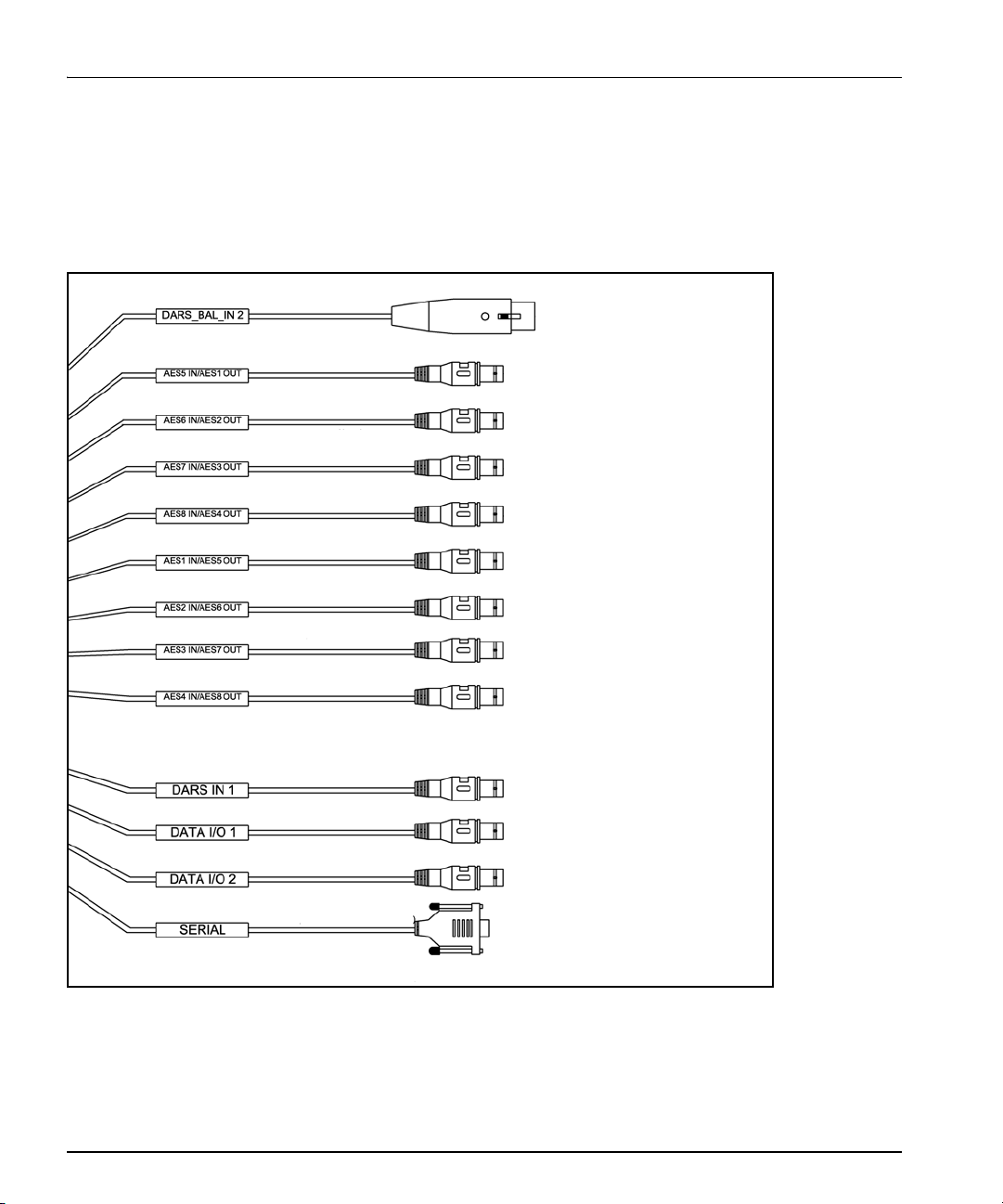
Balanced AES 5 in (female)
Balanced AES 6 in (female)
Balanced AES 7 in (female)
Balanced AES 8 in (female)
Balanced AES 1 in (female)
Balanced AES 2 in (female)
Balanced AES 3 in (female)
Balanced AES 4 in (female)
DARS balanced in
DARS in
Data I/O
Genlock
Serial
Chapter 1: Introduction
Figure 1-4. HMX6800+BC8 Balanced-Audio Breakout Cable
(Part Number 6800+OPT+16+XF)
If you need to make your own breakout cable, pinouts are listed in
Table 1-2, and pin numbers for the 44-pin connector are listed in
Figure 1-5.
HMX6800+BC8 Installation and Operation Manual 7

Chapter 1: Introduction
Figure 1-5. Pin Numbers for 44-pin Connector
Table 1-2. Pinouts for 44-pin Connector
Pin No.
on
Description
DB-44M
30 Balanced AES1B (-)
44 Balanced AES1B (+) XLR5(XLR-3F) Blue
27 Balanced AES5B (-) XLR1(XLR-3F) Blue
41 Balanced AES5B (+) XLR1(XLR-3F) Blue
42 Balanced AES2B (-) XLR6(XLR-3F) Blue
43 Balanced AES2B (+) XLR6(XLR-3F) Blue
24 Balanced AES6B (-) XLR2(XLR-3F) Blue
38 Balanced AES6B (+) XLR2(XLR-3F) Blue
14 Balanced AES3B (-) XLR7(XLR-3F) Blue
15 Balanced AES3B (+) XLR7(XLR-3F) Blue
3 Balanced AES73B (-) XLR3(XLR-3F) Blue
18 Balanced AES7B (+) XLR3(XLR-3F) Blue
29 Balanced AES4B (-) XLR8(XLR-3F) Blue
28 Balanced AES4B (+) XLR8(XLR-3F) Blue
Connection Type on
Unbalanced Cable
Not connected
Connection Type on
Balanced Cable
XLR5(XLR-3F) Blue
Cable
Color
33 Balanced AES8B (-) XLR4(XLR-3F) Blue
34 Balanced AES8B (+) XLR4(XLR-3F) Blue
17 Balanced DARS In 2 (-) XLR9(XLR-3F) XLR9(XLR-3F) White
16 Balanced DARS In 2 (+) XLR9(XLR-3F) XLR9(XLR-3F) White
31 Balanced Serial In (-) 162A10019X 162A10019X Green
32 Balanced Serial In (+) 162A10019X 162A10019X Green
39 Balanced Serial Out (-) 162A10019X 162A10019X Green
40 Balanced Serial Out (+) 162A10019X 162A10019X Green
8 HMX6800+BC8 Installation and Operation Manual

Table 1-2. Pinouts for 44-pin Connector
Chapter 1: Introduction
Pin No.
on
Description
DB-44M
1 DATA I/O 2 BNC11 BNC11 Yellow
2 DATA I/O 2 GND BNC11-GND BNC11-GND Yellow
36 Unbalanced AES1 BNC5
12 Unbalanced AES5 BNC1 White
13 Unbalanced AES5 GND BNC1-GND White
21 Unbalanced AES2 BNC6 White
10 Unbalanced AES6 BNC2 White
11 Unbalanced AES6 GND BNC2-GND White
6 Unbalanced AES3 BNC7 White
7 Unbalanced AES3 GND BNC7-GND White
23 Unbalanced AES7 BNC3 White
22 Unbalanced AES7 GND BNC3-GND White
4 Unbalanced AES4 BNC8 White
5 Unbalanced AES4 GND BNC8-GND White
Connection Type on
Unbalanced Cable
Connection Type on
Balanced Cable
Not connected
Cable
Color
White
26 Unbalanced AES8 BNC4 White
25 Unbalanced AES8 GND BNC4-GND White
RS232_GND DB 9.5 DB 9.5 Black
35 Unbalanced AES2 GND BNC6-GND Not connected White
RS422_FR_GND DB 9.1 DB 9.1 B lack
37 Unbalanced AES1 GND/ BNC5-GND Not connected White
RS422_FR_GND DB 9.9 DB 9.9 B lack
19 Unbalanced DARS In 1 BNC9 BNC9 White
20 Unbalanced DARS In 1 GND BNC9-GND BNC9-GND White
8 DATA IO 1 BNC10 BNC10 Yellow
9 DATA IO 1 GND BNC10-GND BNC10-GND Yellow
HMX6800+BC8 Installation and Operation Manual 9

Chapter 1: Introduction
RS-422/RS-232 Cable
Table 1-3. Pin Assignment of DB-9 Connector (Female) in
RS-422 Format
Pin No. Signal Comments
1 FG Frame Ground
9 FG Frame Ground
5 FG Frame Ground
2 TA(Tx-) Transmitted Data 7 TB(Tx+) Transmitted Data +
8 RA(Rx-) Received Data 3 RB(Rx+) Received Data +
4
6
Not connected
Table 1-4. Pin Assignment of DB-9 Connector (Female) in
RS-232 Format
Pin No. Signal Comments
1 FG Frame Ground
9 FG Frame Ground
5 FG Frame Ground
2 Tx Transmitted Data
7
8
3 Rx Received Data
4
6
Not connected
Not connected
10 HMX6800+BC8 Installation and Operation Manual
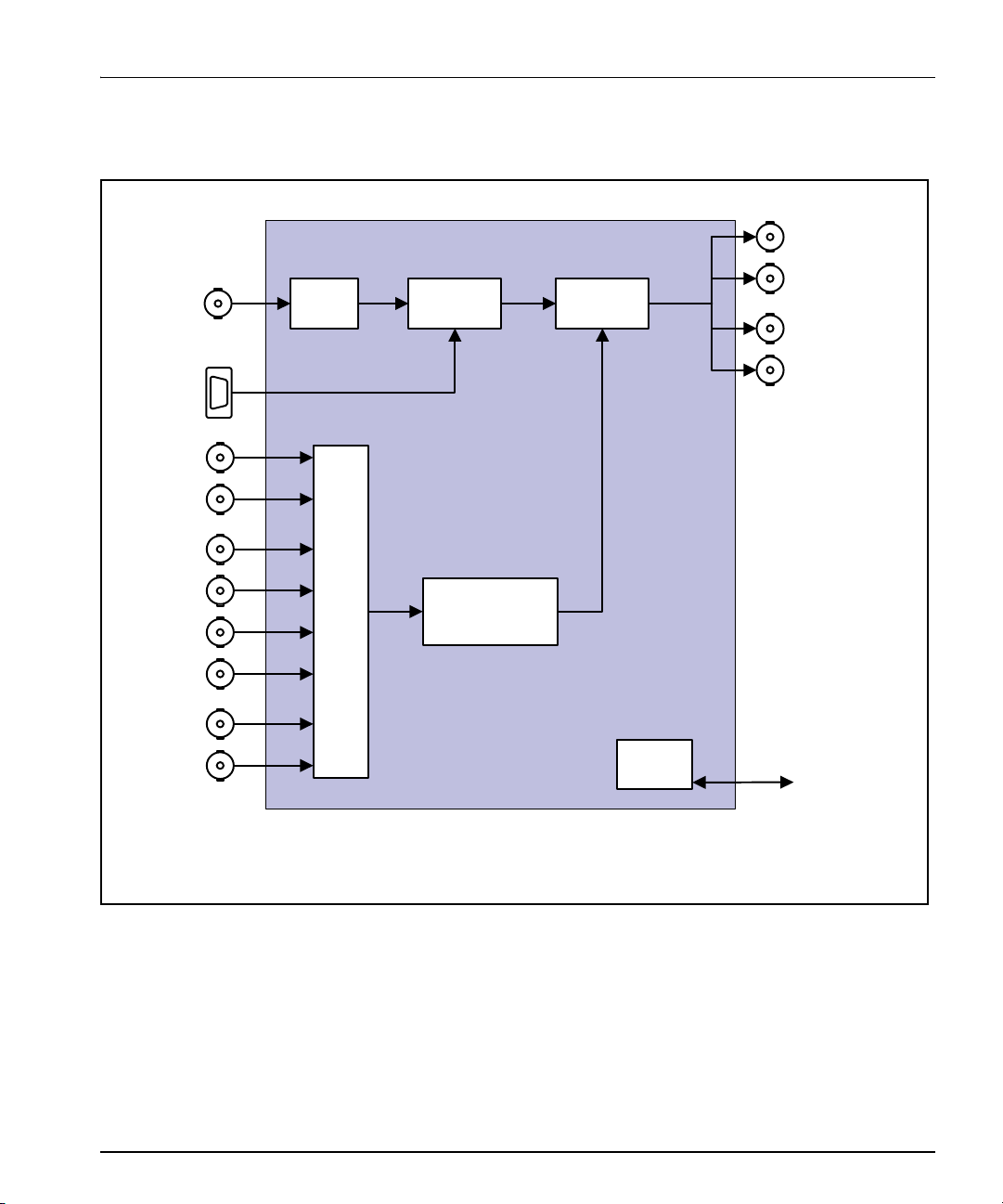
Signal Flow
Midplane
I/O
CCS and Q-SEE
remote monitoring
and control
Video
proc
Metadata
embedder
Audio
embedder
AES in 1
1
AES in 2
1
AES in 3
1
AES in 4
1
AES in 5
1
AES in 6
1
AES in 7
1
AES in 8
1
HD/SD-SDI out 1
HD/SD-SDI out 2
HD/SD-SDI out 3
HD/SD-SDI out 4
HD /SD-SDI in
Metadata in
9
Audio procDelay
1
AES unbalanced (BNC) connections via breakout cable (included).
Balanced (XLR) AES inputs available with optional balanced breakout
cable (ordered separately).
Chapter 1: Introduction
Figure 1-6. HMX6800+BC8 Signal Flow Diagram
HMX6800+BC8 Installation and Operation Manual 11

Chapter 1: Introduction
12 HMX6800+BC8 Installation and Operation Manual

Overview
Caution
Chapter 2
Installation
This chapter describes the HMX6800+BC8 installation process,
including the following topics:
• “Maximum 6800+ Frame Power Ratings” on page 14
• “Unpacking the Module” on page 15
• “Setting Jumper CJ1 for Local or Remote Control” on page 16
• “Installing 6800+ Modules” on page 17
• “Upgrading Module Firmware” on page 18
See the FR6802+ Frame Installation and Operation Manual for
information about installing and operating an FR6802+ frame and its
components.
Before installing this product, read the 6800+ Series Safety
Instructions and Standards Manual shipped with every
FR6802+ Frame Installation and Operation Manual or
downloadable from our website. This safety manual contains
important information about the safe installation and
operation of 6800+ series products.
HMX6800+BC8 Installation and Operation Manual 13

Chapter 2: Installation
Maximum 6800+ Frame Power Ratings
The power consumption for the HMX6800+BC8 module is 12 W.
Table 2-1 describes the maximum allowabl e po we r ratings for 6800+
frames. Note the given maximums before installing any 6800+ modules
in your frame.
Table 2-1. Maximum Power Ratings for 6800+ Frames
6800+ Frame
Type
FR6802+XF
(frame with AC power
supply)
FR6802+XF48
(frame with DC power
supply)
FR6802+QXF frame
(with AC or DC power
supply)
Max. Frame
Power
Dissipation
120 W 20 6 W
105 W 20 5.25 W
120W 20 6 W
Number
of Usable
Slots
Max. Power
Dissipation
Per Slot
14 HMX6800+BC8 Installation and Operation Manual

Note
Unpacking the Module
Preparing the Product for Installation
Before you install the HMX6800+BC8, perform the following:
• Check the equipment for any visible damage that may have
occurred during transit.
Contact your Customer Service
representative if parts are
missing or damaged.
• Confirm receipt of all items on the packing list. See “Checking the
Packing List” for more information.
• Remove the anti-static shipping pouch, if present, and all other
packaging material.
• Retain the original packaging materials for possible re-use.
See “Unpacking/Shipping Information” on page ix for information
about returning a product for servicing.
Chapter 2: Installation
Checking the Packing List
\
Table 2-2. Available Product Packages
Ordered Product Content Description
HMX6800+
6800+OPT+16+C One breakout cable with unbalanced audio
6800+OPT+16+XF One breakout cable with balanced audio
BC8D
• One HMX6800+BC8 front module
• One double-slot back connector
• One 6800+OPT+16+C breakout cable with
unbalanced audio connectors
• One HMX6800+BC8 Installation and
Operation Manual
connectors
connectors
HMX6800+BC8 Installation and Operation Manual 15
CJ1 jumper
Note
Remote control setting
Local control setting
3 2 1 3 2 1
Chapter 2: Installation
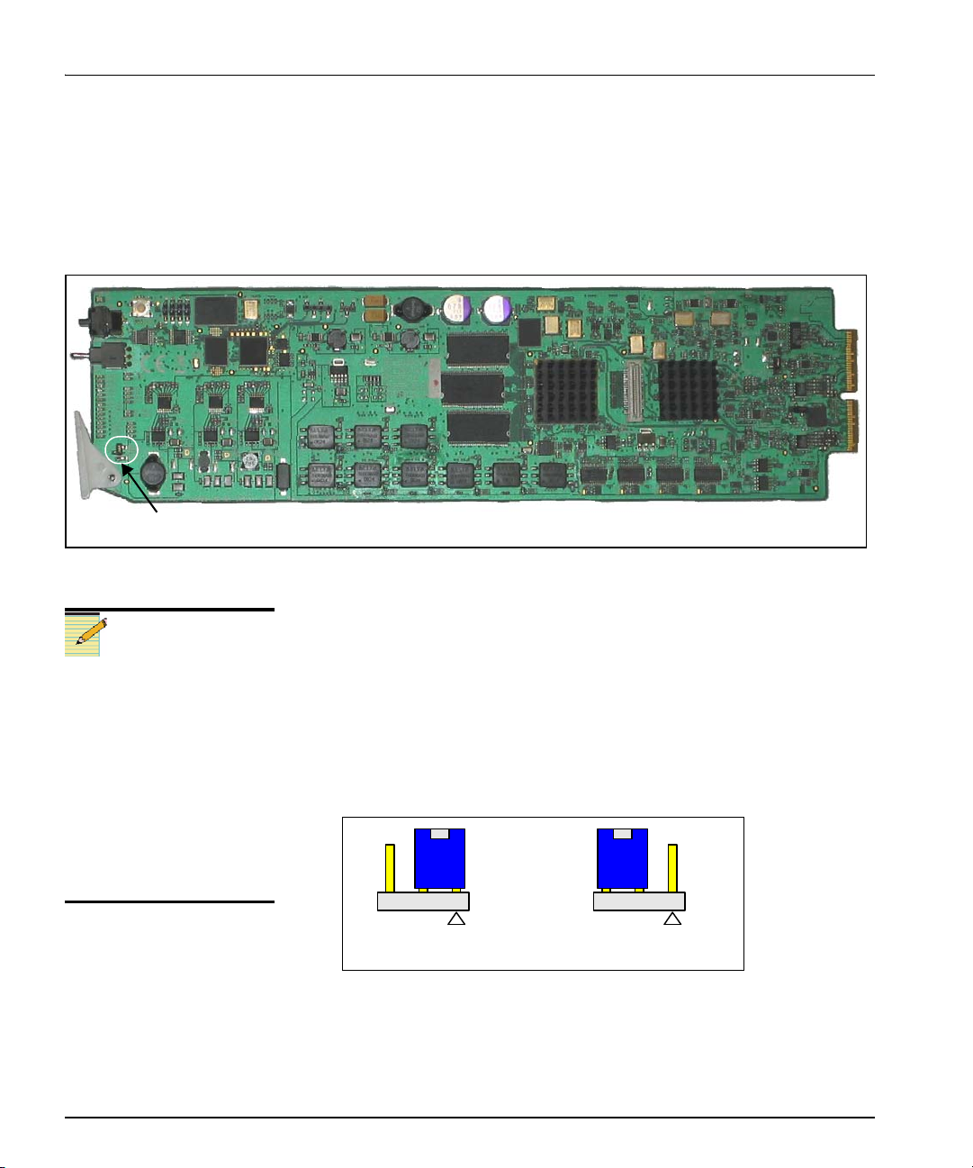
Setting Jumper CJ1 for Local or Remote
Control
The HMX6800+BC8 module has one jumper, CJ1, which sets the
module for local or remote control.
Figure 2-1. Jumper Locations
Follow this procedure to set the CJ1 jumper for either local or remote
control:
You need to configure
modules for local or remote
operation prior to power-up.
To change the configuration,
first remove power from the
module, reset the jumper,
and then reapply power.
The white triangle near the
jumper pins on the module
indicates pin 1.
1. Locate jumper CJ1 on the module (behind the extractor handle).
2. Place a jumper on pins 1 and 2 to set the module for Remote
Figure 2-1 shows the location of the CJ1 jumper.
control, or pins 2 and 3 to set the module for Local control. See
Figure 2-2.
Figure 2-2. CJ1 Settings for Local and Remote Control
16 HMX6800+BC8 Installation and Operation Manual

Installing 6800+ Modules
Required Frames and Back Connector Types
The HMX6800+BC8 modules have double-width back connectors that
can be installed in anor FR6802+QXF frame. HMX6800+BC8
modules cannot be installed in a FR6802+DM frame, a FR6800/7000
frame, or a frame without fans.
See the FR6802+ Frame Installation and Operation Manual for details
on installing back connectors in an FR6802+ frame.
A FR6802+RM (rear support extension rails for 6800+ series frames)
option is recommended for the HMX6800+BC8 modules. See your
FR6802+ Frame Installation and Operation Manual for installation
instructions.
Installing and Removing Modules
These modules require no specialized installation or removal
procedures. However, if installing both front and rear modules, ensure
that the back module is installed first before plugging in the front
module. When removing both the front and rear modules, ensure that
the front module is unplugged from the frame first, before removing the
rear module.
• See the FR6802+ Frame Installation and Operation Manual for
information about installing and operating an FR6802+ frame and
its components.
Chapter 2: Installation
• See the 6800+ Safety Instructions and Standards Manual for
important information about safely installing your module.
Once you have installed your HMX6800+BC8 modules, you can
connect them to the appropriate input and outputs.
HMX6800+BC8 Installation and Operation Manual 17
 Loading...